Article

Control of Triple-Shock Configurations and Vortex Structures Forming in High Speed Flows of Gaseous Media past an AD Body under the Action of External Energy Sources †

by
Olga A. Azarova
1,*,‡ and
Ludmila G. Gvozdeva
2,‡
1
Department of Mathematical Modeling of Computer-Aided Design Systems, Dorodnicyn Computing Centre, Federal Research Center “Computer Science and Control” of Russian Academy of Sciences, Moscow 119333, Russia
2
Department of Physical Gas Dynamics, Joint Institute for High Temperatures of Russian Academy of Sciences, Moscow 125412, Russia
*
Author to whom correspondence should be addressed.
This paper is based on the results presented in the Proceedings of the 22nd International Shock Interaction Symposium, Glasgow, UK, 4–8 July 2016 and the XV International Workshop on Magneto-Plasma Aerodynamics, Moscow, Russia, 19–21 April 2016.
These authors contributed equally to this work.
Aerospace 2017, 4(1), 9; https://doi.org/10.3390/aerospace4010009
Submission received: 28 December 2016 / Revised: 14 February 2017 / Accepted: 15 February 2017 / Published: 20 February 2017
(This article belongs to the Special Issue Fluid-Structure Interactions)

Abstract

:
The problem of supersonic streamlining of an aerodynamic (AD) body, “a plate blunted by a cylinder”, by a flow with the freestream Mach number M = 4 containing an external energy source has been studied, taking into account physicochemical transformations. The results of the effect of the ratio of specific heats γ changing in the range from 1.1 to 1.4 on the dynamics of triple-shock configurations and vortex-contact structures are presented for the interaction of an energy source with the bow shock wave. The energy source is modeled via the heated rarefied layer (filament). The angles in the triple-shock configurations, the stagnation pressure, together with the frontal drag force, have been studied dependent on the specific heats ratio γ, the characteristics of the energy source, and also on the angle of the incident shock. Vortex-contact structures have been researched for the Mach numbers 7, 8, 9, as well as the generation of the Richtmyer-Meshkov instability accompanying the formation of a triple-shock configuration. The results show a strong influence of the specific heats ratio of the gas medium and the parameters of the energy source on the triple-shock configuration and aerodynamic characteristics of the body. This conclusion can be useful for aerospace applications in the area of the design of nozzles, intakes, and high speed flying vehicles. Additionally, the results show the possibility of flow control in the atmospheres of other planets using external energy deposition.

1. Introduction

Supersonic flow control using energy deposition in different places in the flow and on an AD body’s surface has been widely researched in modern aerospace engineering [1,2,3]. The problem of the unsteady flow reorganization under the action of an external energy release was posed in [4] on an example of supersonic streamlining a sphere. Recently the direction of control of specific flow elements (bow shock, separation areas, heat flows, and so on) via the energy deposition of different types is rapidly developing. The control of triple-shock configurations, vortex structures, and characteristics of an AD body using energy release dislocated in an oncoming flow in such types of problems for different gas media and gas mixtures was suggested in [5].
The effect of the external energy source in an oncoming flow in air was shown to lead to a decrease of the stagnation pressure, together with the drag force of the body. Energy sources of different types (microwave, laser, discharge) were used for these purposes [6,7]. Two mechanisms have been established causing this phenomenon, the reflection of a rarefaction wave from the body’s surface [8] and the effect of a vortex structure generating via the interaction of an energy source with a bow shock [6]. The latter effect was named the vortex drag reduction. The reduction of drag force together with the decrease of the stagnation parameters was obtained experimentally and numerically for air, in particular, in [9,10,11]. Effects of a local heating on wave drag reduction were investigated in [12,13,14]. Additionally, it has been stated that the triple-shock configurations accompanied by the vortex-contact structures were generated at the beginning stage of the process of energy release–shock layer interaction when the flow mode is close to the self-similar one [15,16,17].
Triple-shock configurations are basic elements of flowfields both in external and internal aerodynamics [18,19] which defines the essential phenomena occurring in the flow. These configurations include three shock waves which intersect in one point, and also a slipstream issuing from the triple point which aligns the parameters of gas behind the reflected wave and the Mach stem. For the calculation of a triple configuration, two assumptions are usually used: the assumption of a steady flow in the vicinity of the shock wave intersection point and the assumption about the self-similar flow mode in the case of an unsteady flow [20].
In the problems being discussed, changing the structures of the triple-shock configurations connected with physical-chemical transformations and characteristics of an energy source define a significant modification of dynamical and heat loadings on an AD body [9,10]. For strong shock waves when physicochemical reactions occur behind the shock fronts, the self-similarity assumption does not hold true because of relaxation effects. However, in cases where either partial equilibrium or complete thermodynamic equilibrium becomes established behind the shock, the self-similar assumption becomes possible [21].
The steady triple-shock configurations in air, nitrogen, and carbon dioxide were investigated in [22,23]. It has been shown that real gas effects which lead to a decrease in the ratio of specific heats γ strongly influence the relative front positions in a triple-shock configuration. Additionally, in the case of unsteady interaction of shock waves with plane surfaces, the decrease of the ratio of specific heats has been shown to lead to the appearance of a significant flow reconstruction connected with the formation of the double Mach reflection. Recently it has been found that, for a flow around a system of two wedges (a model of an intake) for the Mach numbers higher than 3 and γ < 1.4 it is possible for the oscillation flow mode to appear and destroy the steady flow mode [24,25,26,27].
The behavior of the slip streams in the triple-shock configurations are complex and far from well understood. At some distance from the triple point the slip stream becomes unstable since it is a tangential discontinuity which decays into a vortex chain which curves in a larger vortex. A similar situation has been modeled in [28], together with modeling the Richtmyer-Meshkov instability in the case of supersonic flow past an AD body. In [29] the influence of the ratio of specific heats on the behavior of the slipstreams was investigated. It was shown that the increase of the Mach number and the decrease of an adiabatic index lead to the greater instability of the slipstreams and, as a result, the mixing processes are much more efficient in this case.
This paper is devoted to the problems of the influence of an external energy source on a shock layer initiated by supersonic streamlining the body, “a plate blunted by a cylinder”, under the Mach number of the oncoming flow M = 4 for gaseous media with the specific heats ratio γ in the range from 1.1 to 1.4. Study of flow details and the shape of triple-shock configurations and vortex-contact structures, and research of the dependencies of the angles in a triple-shock configuration on the characteristics of the energy source, as well as on the angle of the incident shock, have been conducted. Additionally, the research of the dependence of stagnation pressure and drag force on γ and the rarefaction factor in the energy source has been made.
For the greater Mach numbers (M = 7, 8, 9) modeling the vortex-contact structures accompanied the formation of triple-shock configurations, together with the generation of the Richtmyer-Meshkov instability, has been made (for M = 8, γ = 1.3). The simulations are based on the complex conservative difference schemes which have enlarged conservation properties both inside the calculation area and near the boundaries of the streamlined body [30].
The results presented can be useful for modeling the flow/flight conditions in air for high speed flows around an AD body as well as in the simulations of flows of gas mixtures streamlining structural elements inside nozzles and intakes. Additionally, the results reflect the possibility of flow control in the atmospheres of other planets (characterized by γ different from 1.4) via the external energy deposition.

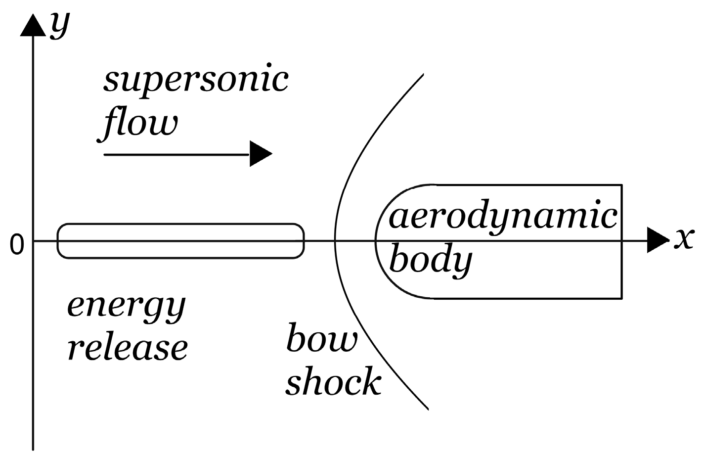
2. Statement of the Problem and Applied Numerical Procedure

The Euler system of equations for perfect inviscid gas with the constant ratio of specific heats γ in the range from 1.1 to 1.4 for the plane flow symmetry is used for the simulations:
U t + F x + G y = 0 , U = ( ρ ρ u ρ v E ) , F = ( ρ u p + ρ u 2 ρ u v u ( E + p ) ) , G = ( ρ v ρ u v p + ρ v 2 v ( E + p ) ) .
Here ρ, p–density, and pressure of the gas, u and v are x- and y-components of the gas velocity, ε = p/(ρ(γ − 1)), Е = ρ(ε + 0.5(u2 + v2)) is the total energy per unit volume, ε is the specific internal energy. The schematic of the considered flow and the calculation area are presented in Figure 1. The initial condition for the problem is a converged supersonic steady flow streamlining an aerodynamic body, “a plate blunted by a cylinder”. Dimensionless freestream parameters are ρ = 1, p = 0.2, u = Mc, and v = 0 (c is the undisturbed speed of sound). The dimensional freestream values of density and pressure obtained with the use of the normalizing parameters for pressure pn = 5.06625 × 10⁵ Pa, for density ρn = 1.293 kg/m3, and for γ = 1.4 correspond to those of air under the normal conditions. We solve the problem in the dimensionless variables. For a chosen value of the normalizing parameter of length ln, the normalizing time parameter is tn = ln/un where un = (pnn)0.5. By this way for ln = 0.1 m; tn = 159.8 µs. In figures in Section 3.1, Section 3.4, Section 3.5 and Section 3.6 below the normalized variables in x- and y-axes are indicated.
Energy release (“filament”) is modeled using a heated rarefied channel/layer via the entrance boundary condition: ρi = αρρ for 0 ≤ y ≤ 0.5d and titti + Δti. Here, ρ is the freestream density, ρi is the density in the energy source (αρ = ρi is a rarefaction factor in the energy source), d is the filament diameter and Δti is the time duration of the energy source action. Pressure and velocity in the energy source are supposed to be the same as in the oncoming flow. Thus, the temperature in the source is increased in comparison with the temperature of the oncoming flow. This model of the external energy deposition via a heated layer was suggested in [31] and has been shown to give a satisfactory approximation of the experimental values of the stagnation pressure in the modeling of the microwave and laser experiments on supersonic flow control [11].
Complex conservative schemes are used in the simulations (see the details of the schemes construction for plane and cylinder flows in [30]). The schemes use the systems of difference consequences for the space derivatives for obtaining the second approximation order (in space and in time). All of the systems are considered in the divergent form which causes the implementation of the conservation laws not only for basic Euler equations, but also for the systems of x- and y-differential consequences of these equations. The schemes use the stencil of the well-known Lax scheme both for the systems of the unknown functions and for the systems of the unknown x- and y-derivatives. In the areas inherent to the body’s boundaries the special modifications of the schemes are used (written for 1 2 , 1 4 , and 3 4 of a grid cell). By this way the boundary conditions are incorporated in the calculations without breaking the conservation laws in the calculation area. The staggered difference grid with 1000 nodes per the body’s diameter is used.

3. Results

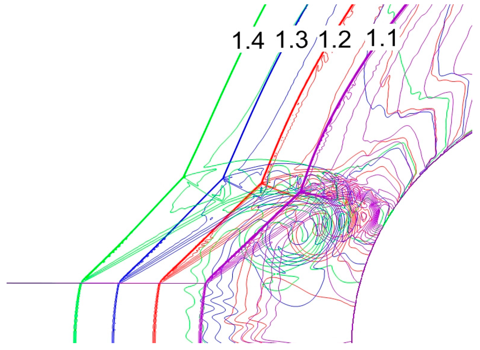
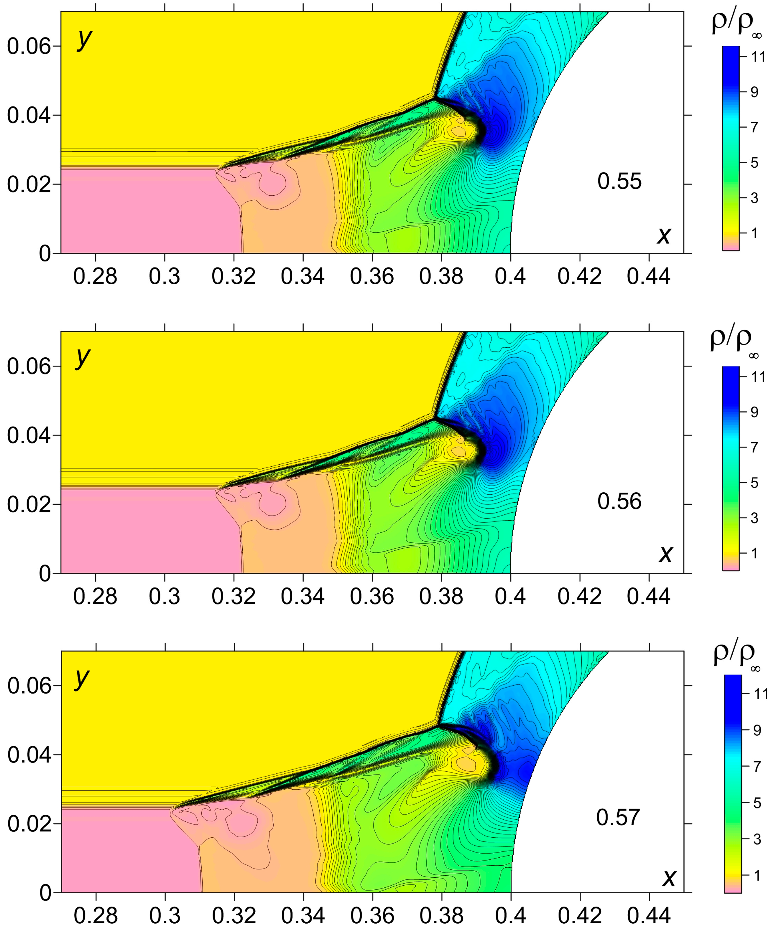
3.1. Dynamics of Formation of a Triple-Shock Configuration and Analogy with the Triple-Shock Theory

Dynamics of formation of the triple-shock configuration for the self-similar type of the flow for γ = 1.2 is presented in Figure 2 (here the dimensionless time moments t are indicated). The angles in the triple-shock configuration do not change practically during the time period because of the self-similar flow mode which gives the possibility to compare the triple-shock configurations for different γ.
For the investigation of the triple-shock configurations the analogy can be applied with the problem of shock wave reflection [21]. In a planar overexpanded nozzle flow two oblique shocks are created that start at the nozzle lips and are directed towards the symmetry plane. These incident shocks can reflect either the regular reflection or the Mach reflection. The scheme of the Mach reflection is given in comparison with the triple-shock configuration forming in the problem with an external energy release (Figure 3).
Actually, comparing the lower triple-shock configuration in Figure 3a with another one in Figure 3b, the precursor plays the role of an incident shock wave (1), the bow shock is a Mach wave (3). Additionally, one can see a reflected wave (2) and a slip line (or shear layer—(4), Figure 3b). The angles with these elements and the flow direction have been considered (Figure 4). Figure 5 shows that the shape of a triple-shock configuration changes considerably with γ. This figure was obtained via the overlay of four flow images with γ = 1.1, 1.2, 1.3, and 1.4.

3.2. Study of the Angles in Triple-Shock Configuration for Different γ

Dependences of the angles between the elements of the triple-shock configurations with the flow direction on γ have been obtained in [5] (Figure 6). One can see that the angle formed by the reflected shock ω2 is changing significantly with γ decreasing from 1.4 to 1.1 (by 51.8% for αρ = 0.5), the angle of the Mach wave ω3 changes not so strongly (by 11.5% for αρ = 0.5) and the angles ω1 and ω4 are practically independent of γ. It has been established that the angle ω1 is well approximated (about 3% for moderate αρ) by the relation:
sin2ωpr = αρ
which was obtained in [31] for the precursor angle ωp. Thus, ω1 increases against αρ. In its turn the calculations have shown that the precursor angle is very well described by Equation (2) for γ from 1.4 to 1.1 (with the deviation about 0.3%–0.4% for moderate αρ) and is independent of γ (together with ω1). Thus, it is possible to research the angles in triple-shock configurations in dependence on the angle of an incident shock ω1 from the point of view of the three-shock theory (see [21]). For this purpose the transition to a system of reference connected with the triple point has to be done.
Behaviour of the considered angles for αρ changing in the interval (0.11; 0.66) against the angle ω1ρ) for different γ is presented in Figure 7 and Figure 8. It is obtained that the angle of the reflected shock ω2 has a local minimum in the considered interval, the angle of the Mach shock ω3 decreases slightly against ω1 (and against αρ, too) and the angle of the contact discontinuity ω4 increases against ω1 (and against αρ, too). At the same time ω2 decreases with decreasing γ, ω3 slightly increases with decreasing γ and the dependence on γ is not looked through the behaviour of ω4.

3.3. Accuracy of the Angles’ Calculations

Although the scheme accuracy of the calculations of shock front positions constitutes tenth parts of a percent the total accuracy of a triple-shock configuration angles evaluation is greater. It is connected with using the flow images for the angle calculations. We have used the enlarged flow images and calculated the angles through the coordinates of the centres of the triple-shock configurations and the points on the shock fronts in the neighbourhood of the centre where the fronts are close to straight lines (via the facilities of a graphical editor). The precision is 1°–2° for moderate αρ1 varies from 30° to 60°) and 3°–4° for small αρ1 varies from 20° to 30°).
It should be noted that the boundary conditions can affect the details of forming a triple-shock configuration [32]. To evaluate this influence, the simulations have been made on the enlarged calculation area: 0 ≤ x ≤ 0.5, 0 ≤ y ≤ 0.5. For αρ = 0.5 and γ = 1.4 the difference in the calculations of the angles was 0.9° for ω1, 3.4° for ω2, 1° for ω3 and 2.7° for ω4.

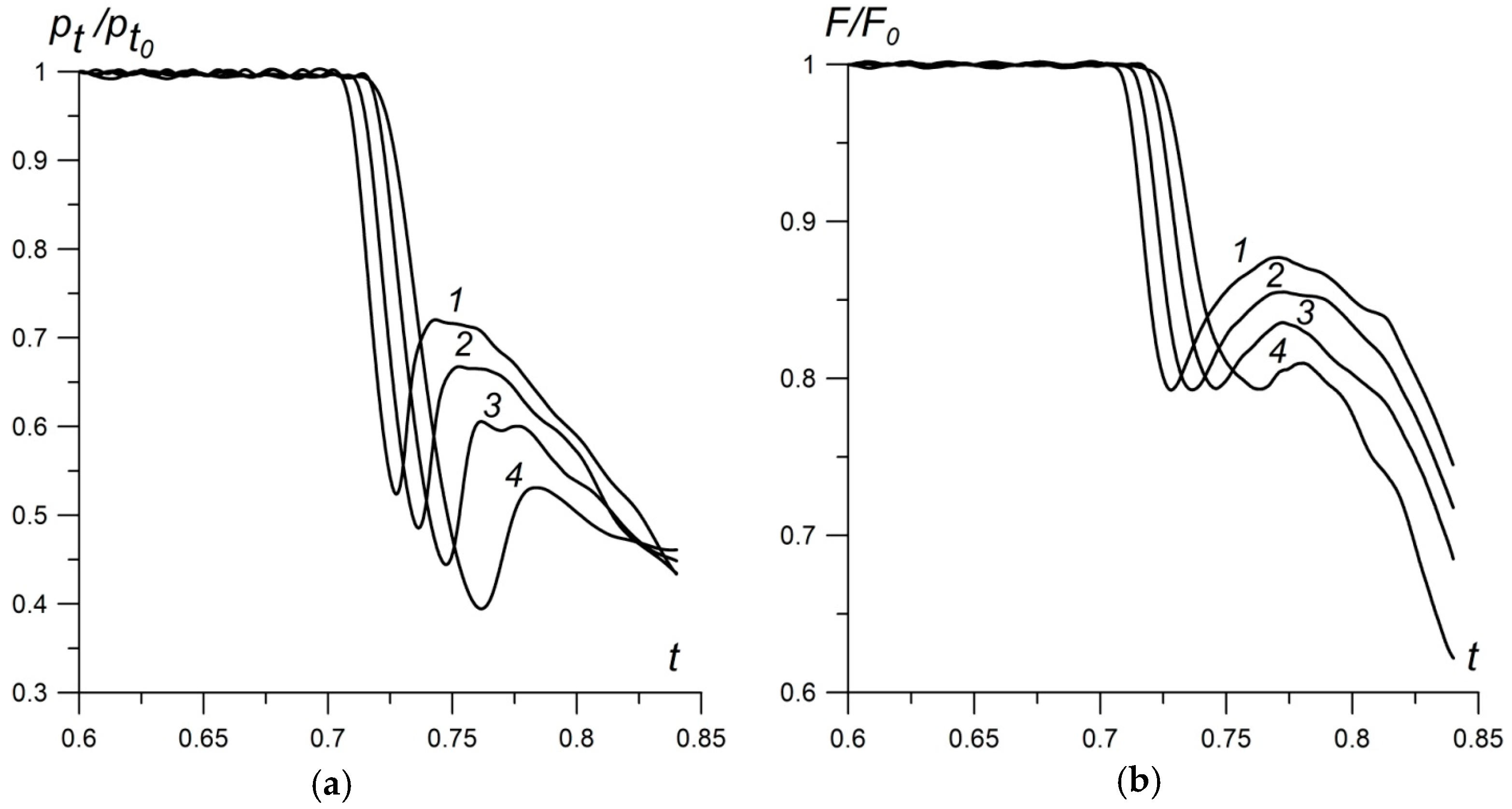
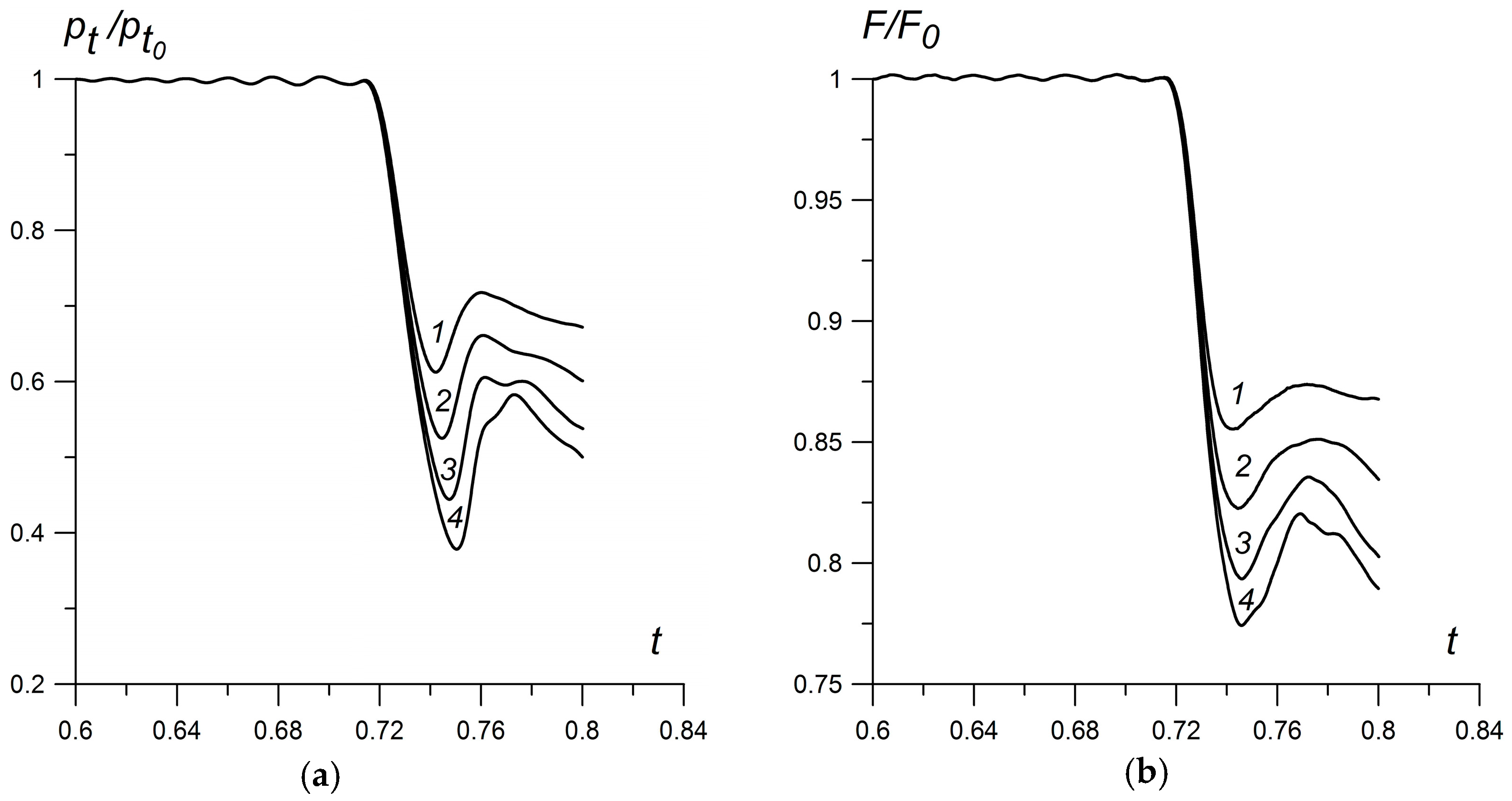
3.4. A Study of the Stagnation Pressure and Frontal Drag Force for Different γ

The dynamics of the stagnation pressure pt and the front drag force F have been studied in this section (see Figure 9, subscript “0” refers to the values of the parameters in the absence of the energy source). The first minimum in the curves is caused by a rarefaction wave reflection which is generated at the very beginning of the interaction process (see [8]). This rarefaction wave is an element of the solution of the Riemann problem which describes the interaction of the boundary of the heated area with the bow shock. In [11] it has been shown that the next decline for the similar shape of the body is connected with the action of the vortex structure on the body’s boundary. The mechanism of this vortex formation has been shown to be connected with Richtmyer-Meshkov instability generation [28]. The drag reduction initiated by the vortex of this type has been obtained numerically in [6].
With decreasing γ the stagnation pressure decreases (by 24.7% for ω1 = 45° and αρ = 0.5) and the frontal drag force decreases, too (by 16.5% for ω1 = 45° and αρ = 0.5). It is seen that the pressure decline (together with the drag force) at the first stage is greater for smaller γ, but the stagnation pressure decline has no effect on the decreasing of the drag force. On the contrary, the vortex action at the next stage is significantly large for smaller γ and causes the essential drag force reduction. Thus, in this case a new qualitative behaviour of the drag force, which is greater for smaller γ, due to the vortex action takes place.
The effect of the ratio of specific heats on the flow geometry is connected with changing the basic defining flow parameters, such as the speed of sound, equation of state, enthalpy, and others. The enhancement of the considered effects of stagnation pressure and drag force decrease with decreasing γ is connected with greater pressure drops between the values on the boundaries of the rarefaction wave and between the centre and periphery pressure values of the vortex for smaller γ.
Figure 10 presents the behaviour of the relative stagnation pressure and relative drag force for a rarefaction factor αρ in an area of the energy release, here γ = 1.2 (the according angles ω1 are defined).
One can see that with decreasing the density (or increasing the temperature) of the gas medium in a region of the energy source, the stagnation pressure on the body’s surface declines (together with the front drag force). The analogous conclusion for air (γ = 1.4) has been obtained in [6]. Thus, the trend of decreasing the stagnation pressure and the drag force which is greater for smaller αρ (and higher temperature) continues for gas media with γ < 1.4.

3.5. Shock Structure in the Case of γ = 1.1 and Small αρ

The consideration of the flow details in the area of generated shock structure for the case of small γ (γ = 1.1) and small αρρ = 0.117) is presented in this subsection. The dynamics of the formation of the triple-shock configuration is shown in Figure 11 (dimensionless time t values are indicated). It is seen that, in this case, the precursor front is not a straight line and it consists of several λ-waves. Additionally, the shock front inside the energy source is not a straight line, too, due to a vortex flow structure in the area of the precursor–source boundary interaction. Nevertheless, it should be noted that the angle of the precursor front in this area is well approximated by Equation (2) and is close to 20°. The front of the reflected shock in the triple configuration is curved and for the angle evaluation we consider the small area of a centre of the triple configurations where the fronts are close to straight lines. It is interesting that the angle ω4 is slightly negative in these simulations, but its value is close to the value of error bar for this angle.

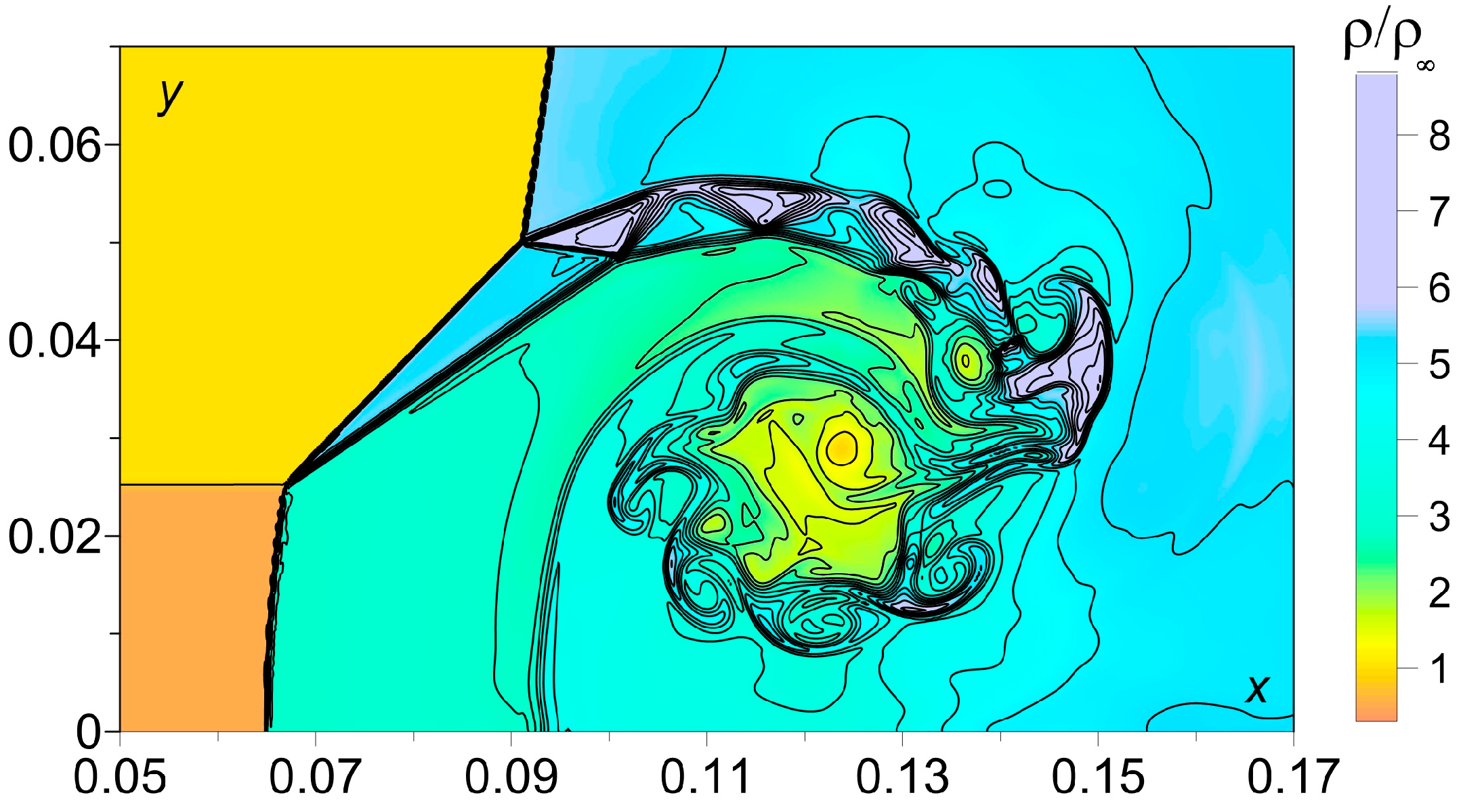
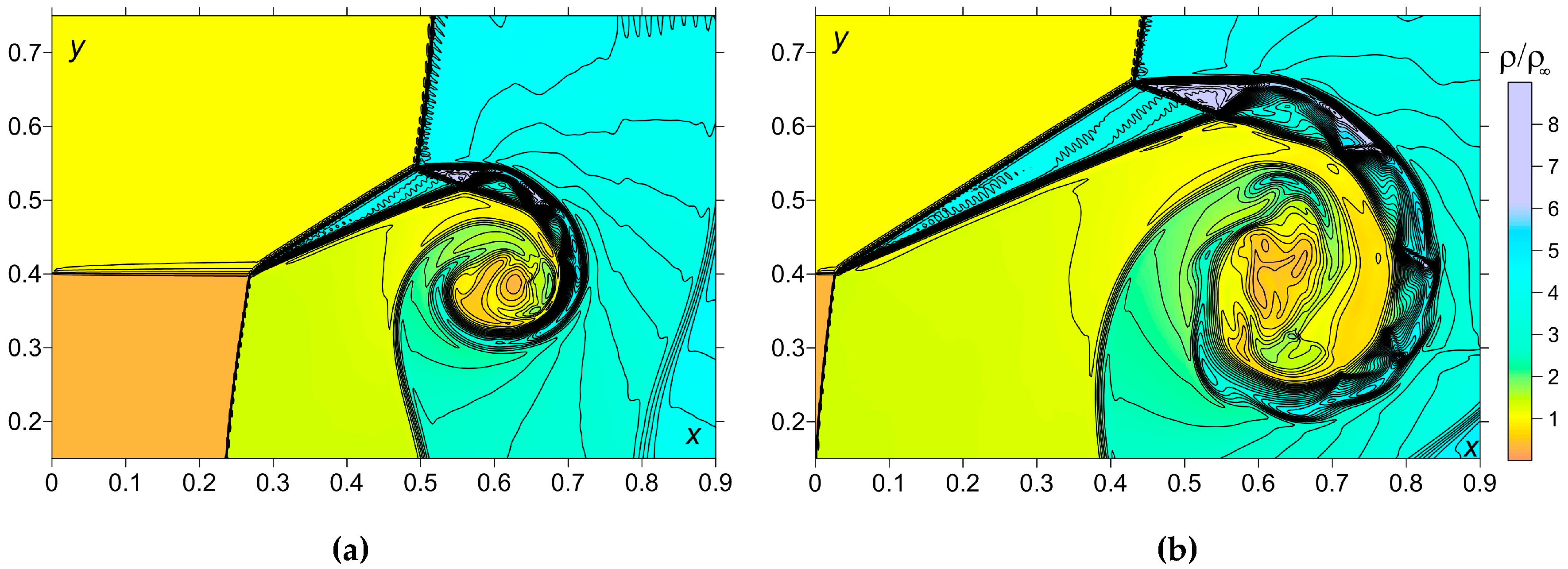
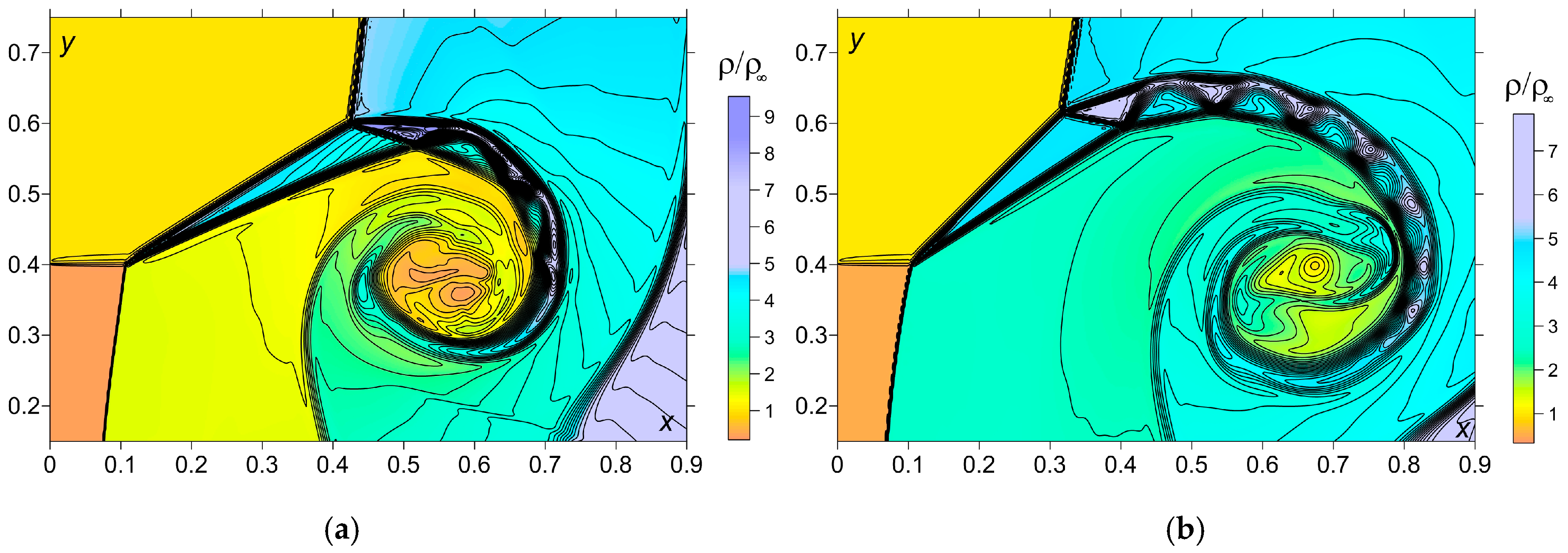
3.6. Modeling the Vortex-Contact Structures and the Richtmyer-Meshkov Instability

Here a model problem of a plane shock wave—heated layer interaction is considered for modeling the vortex-contact structures for the greater Mach numbers. This problem models the situation which takes place in the considered problems of supersonic streamlining a body by a flow containing an external energy source. For the great Mach numbers the formation of the triple-shock configuration is accompanied by a more complicated vortex-contact structure (Figure 12, Results in Figure 12 and Figure 13 were obtained on the coarse grid with 500 × 500 nodes on the calculation area (1.0 × 1.0)). This structure includes two contact discontinuities (shear layers). Between these shear layers there arises a flow structure consisting of multiple reflected simple waves (rarefaction waves reflect as compression waves and compression waves reflect as rarefaction waves). The examples of such types of structures for M = 9 are presented in Figure 13.
These flow structures are similar to those which are generated in the shock–shock interaction of “Edney IV type” (see [33]) where the bow shock interacts with the impinging oblique shock. The schematic of the “Edney IV” shock–shock interaction and a wide review of this subject are presented in [34]. Additionally, the similar structures with multiple reflected simple waves have been obtained in [35] in the neighbourhood of the face of a plate under the action of asymmetrically dislocated energy release. The mechanism of formation of such types of structures has been described, also.
At some time in the obtained vortex structures an intersection of characteristics has taken place causing the “overturn” of the front profile in a compression wave and generation of a secondary shock wave. This shock wave interacts with the contact discontinuity (shear layer) which is dislocated under an angle to the shock front being a reason of the Richtmyer-Meshkov instability generation [36] (Figure 14, here M = 8, γ = 1.3, αρ = 0.5). One can see the primary vortex generated by the Richtmyer-Meshkov instability accompanied by the secondary vortices originated due to the Kelvin-Helmholtz instabilities. Note that the second upper vortex initiated by the Richtmyer-Meshkov instability is suppressed by the high-speed flow. In [28] the other mechanism of the Richtmyer-Meshkov instability is described for these problems. Thus, the conclusion of typicality of such kinds of instability for increasing the Mach number and decreasing γ in the considered class of problems can be accomplished.

4. Conclusions

Unsteady Mach triple-shock configurations have been studied at the first stage of the process of interaction of an energy source with a shock layer in the flow mode close to the self-similar one. The dependences of the angles of a triple-shock configuration on γ changing from 1.1 to 1.4, on the rarefaction degree of a gas in an energy source αρ and on the angle of incidence ω1 have been obtained for freestream Mach number 4. The conclusions on the angles evaluation are as follows:
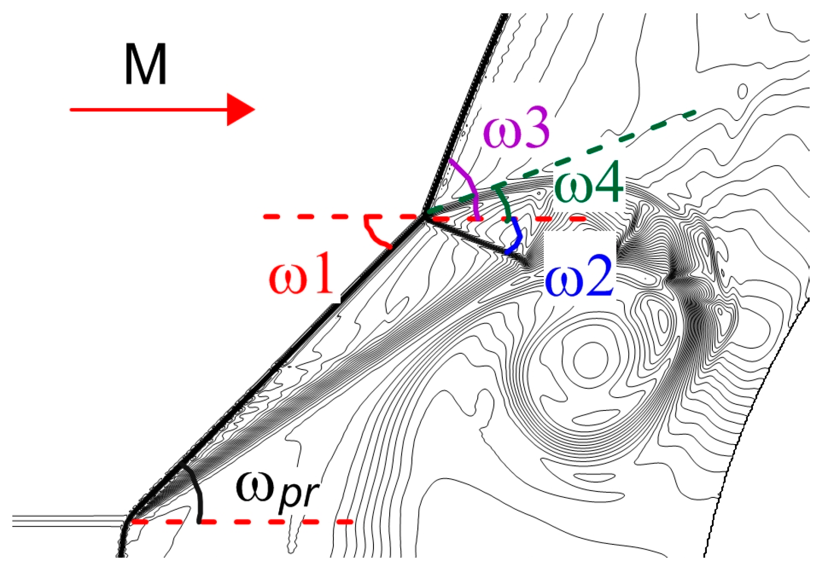
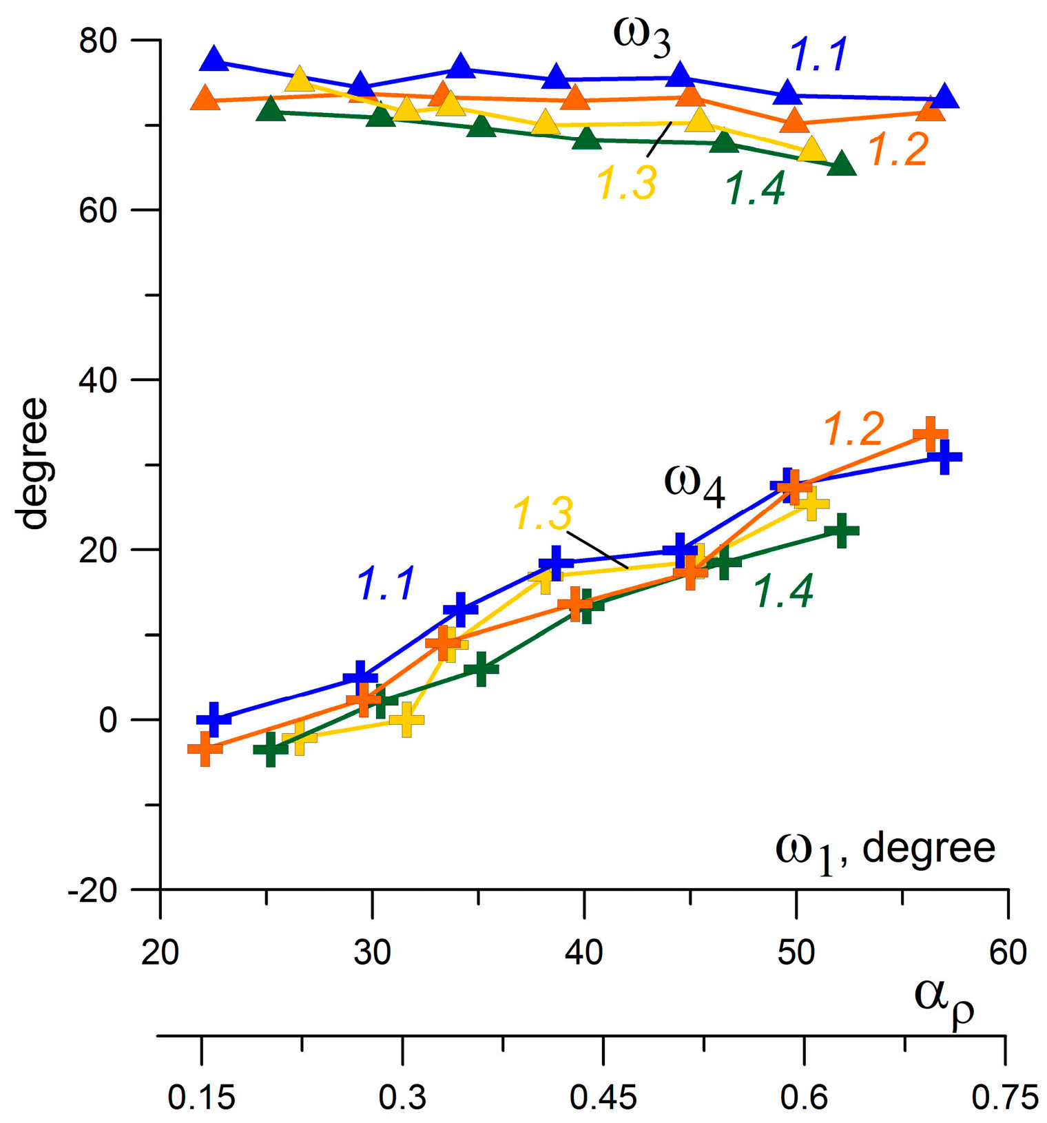
  • For the evaluation of the angle of incident shock ω1 Equation (2) can be used, which gives the connection of ω1 and the rarefaction parameter αρ of a gas in an energy source.
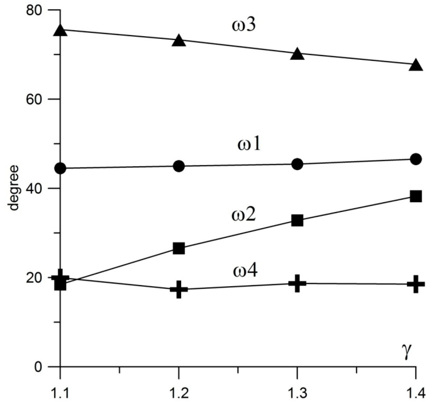
  • The angle of incident shock ω1 is independent of γ.
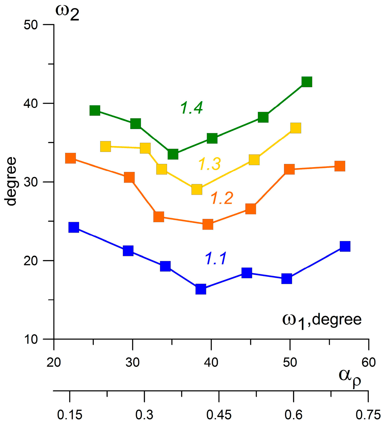
  • With decreasing γ from 1.4 to 1.1 the angle of the reflected shock ω2 decreases (by 51.8% for ω1 = 45° and αρ = 0.5), the angle of the Mach shock ω3 increases (by 11.5% for ω1 = 45° and αρ = 0.5), and the angle of the contact discontinuity ω4 is practically independent of γ.
  • The angle of the contact discontinuity ω4 increases against αρ (and against ω1), the angle of the reflected shock ω2 has a local minimum in the considered intervals of αρ and ω1, and the angle of the Mach shock ω3 decreases slightly against αρ (and against ω1).
The stagnation pressure together with the frontal drag force have been studied for γ changing from 1.1 to 1.4 for different αρ. It has been shown that with decreasing γ the stagnation pressure decreases (by 24.7% for ω1 = 45° and αρ = 0.5) and the frontal drag force decreases (by 16.5% for ω1 = 45° and αρ = 0.5), the latter effect is due to the intensification of the vortex drag reduction. At the same time the results showed that the trend of the decreasing of the stagnation pressure and the drag force which is greater for smaller αρ continues for gas media with γ < 1.4.
For M = 7, 8, 9 the complicated shock structures (accompanying the formation of the triple-shock configurations) have been obtained which are characterized by the multiple reflection of simple waves (rarefaction waves and compression waves). Generation of the Richtmyer-Meshkov instability has been modeled for M = 8 and a conclusion about the typicality of such kinds of instability for increasing Mach number and decreasing γ in the considered problems has been made.

Acknowledgments

The research is partially supported by RFBR under the Projects No. 16-08-01228 and No. 15-01-04635.

Author Contributions

Ludmila G. Gvozdeva formulated the problem; Olga A. Azarova performed the calculations; Ludmila G. Gvozdeva and Olga A. Azarova analyzed the data and wrote the paper.

Conflicts of Interest

The authors declare no conflict of interest.

References

  1. Knight, D. Survey of aerodynamic drag reduction at high speed by energy deposition. J. Propuls. Power 2008, 24, 1153–1167. [Google Scholar] [CrossRef]
  2. Knight, D. A short review of microwave and laser discharges for supersonic flow control. AerospaceLab 2015, 10, 1–12. [Google Scholar] [CrossRef]
  3. Russel, A.; Zare-Bentash, H.; Kontis, K. Joule heating flow control methods for high-speed flows. J. Electrost. 2016, 80, 34–68. [Google Scholar] [CrossRef]
  4. Georgievsky, P.Y.; Levin, V.A. Supersonic flow over bodies in the presence of external energy input. Pis’ma Zhurnal Tekh. Fiziki 1988, 14, 684–687. (In Russian) [Google Scholar]
  5. Azarova, O.A.; Gvozdeva, L.G. Unsteady triple-shock configurations and vortex contact structures initiated by the interaction of an energy source with a shock layer in gases. Tech. Phys. Lett. 2016, 42, 799–803. [Google Scholar] [CrossRef]
  6. Kolesnichenko, Y.F.; Brovkin, V.G.; Azarova, O.A.; Grudnitsky, V.G.; Lashkov, V.A.; Mashek, I.C. Microwave Energy Release Regimes for Drag Reduction in Supersonic Flows. In Proceedings of 40th AIAA Aerospace Sciences Meeting & Exhibit, Reno, NV, USA, 14–17 January 2002; American Institute of Aeronautics and Astronautics: Reston, VA, USA, 2002; pp. 1–12, AIAA-2002–0353. [Google Scholar]
  7. Tretyakov, P.K.; Fomin, V.M.; Yakovlev, V.I. New principles of control of aerophysical processes research development. In Proceedings of International Conference on the Methods of Aerophysical Research, Novosibirsk, Russia, 29 June–3 July 1996; Khristianovich Institute of Theoretical and Applied Mechanics: Novosibirsk, Russia, 1996; Volume 2, pp. 210–220. [Google Scholar]
  8. Georgievsky, P.Y.; Levin, V.A. Unsteady interaction of a sphere with atmospheric temperature inhomogeneity at supersonic speed. Fluid Dyn. 1993, 28, 568–574. [Google Scholar] [CrossRef]
  9. Knight, D.; Kolesnichenko, Y.F.; Brovkin, V.G.; Khmara, D.; Lashkov, V.A.; Mashek, I. Interaction of microwave-generated plasma with a hemisphere-cylinder at Mach 2.1. AIAA J. 2009, 47, 2996–3010. [Google Scholar] [CrossRef]
  10. Knight, D.; Kolesnichenko, Y.F.; Brovkin, V.G.; Khmara, D.; Lashkov, V.A.; Mashek, I. Interaction of microwave-generated plasma with hemisphere-cone-cylinder. In Proceedings of 48th AIAA Aerospace Sciences Meeting Including the New Horizons Forum and Aerospace Exposition, Orlando, FL, USA, 4–7 January 2010. AIAA-2010–1005. [CrossRef]
  11. Azarova, O.A.; Knight, D.D. Interaction of microwave and laser discharge resulting “Heat spots” with supersonic combined cylinder bodies. Aerosp. Sci. Technol. 2015, 43, 343–349. [Google Scholar] [CrossRef]
  12. Schulein, E.; Zheltovodov, A.A. Effects of steady flow heating by arc discharge upstream of non-slender bodies. Shock Waves 2011, 21, 383–396. [Google Scholar] [CrossRef]
  13. Schulein, E.; Bornhoft, E. Potential of localized flow heating for wave drag reduction. In 28th International Symposium on Shock Waves; Springer: Berlin, Germany, 2012; pp. 615–621. [Google Scholar]
  14. Schulein, E. Simplified model for flow-heating effect on wave drag of blunt bodies and its validation. In Proceedings of 45th AIAA Fluid Dynamics Conference, Dallas, TX, USA, 22–26 June 2015; pp. 1–15, Paper AIAA-2015–2778.
  15. Azarova, O.A. Simulation of stochastic pulsating flows with instabilities using minimum-stencil difference schemes. J. Comp. Math. Math. Phys. 2009, 49, 1397–1414. [Google Scholar] [CrossRef]
  16. Azarova, O.A.; Knight, D.; Kolesnichenko, Y.F. Flow control via instabilities, vortices and steady structures under the action of external microwave energy release. J. Aerosp. Eng. 2013, 227, 1498–1515. [Google Scholar] [CrossRef]
  17. Azarova, O.A.; Knight, D.; Kolesnichenko, Y.F. Pulsating stochastic flows accompanying microwave filament/supersonic shock layer interaction. Shock Waves 2011, 21, 439–450. [Google Scholar] [CrossRef]
  18. Courant, R.; Friedrichs, K.O. Supersonic Flows and Shock Waves; Springer: New York, NY, USA, 1948. [Google Scholar]
  19. Landau, L.D.; Lifshitz, E.M. Fluid Mechanics, 2nd ed.; Pergamon Press: Oxford, UK, 1987; Volume 6, p. 551. [Google Scholar]
  20. Ben-Dor, G. Shock Wave Reflection Phenomena, 2nd ed.; Springer: New York, NY, USA, 2007. [Google Scholar]
  21. Bazhenova, T.V.; Gvozdeva, L.G.; Nettleton, M.A. Unsteady interactions of shock waves. Prog. Aerosp. Sci. 1984, 21, 249–331. [Google Scholar] [CrossRef]
  22. Bazhenova, T.V.; Gvozdeva, L.G.; Lobastov, Y.S.; Naboko, I.M.; Nemkov, R.G.; Predvoditeleva, O.A. Shock Waves in Real Gases; NASA Technical Translation: Washington, DC, USA, 1969; TT-F-58. [Google Scholar]
  23. Bazhenova, T.V.; Gvozdeva, L.G. Unsteady Interaction of Shock Waves; Izdatel'stvo Nauka: Moscow, Russia, 1977; p. 276. (in Russian) [Google Scholar]
  24. Gvozdeva, L.G. Conditions of instability of three shock configuration in steady flows. In Proceedings of 19th International Shock Interaction Symposium (ISIS19), Moscow, Russia, 31 August–3 September 2010.
  25. Gvozdeva, L.G.; Gavrenkov, S.A. Formation of triple shock configurations with negative reflection angle in steady flows. Tech. Phys. Lett. 2012, 38, 372–374. [Google Scholar] [CrossRef]
  26. Gvozdeva, L.G.; Gavrenkov, S.A. A new configuration of irregular reflection of shock waves. Prog. Flight Phys. 2015, 7, 437–452. [Google Scholar]
  27. Gavrenkov, S.A.; Gvozdeva, L.G. Numerical investigation of the onset of instability of triple shock configurations in steady supersonic gas flows. Tech. Phys. Lett. 2012, 38, 587–589. [Google Scholar] [CrossRef]
  28. Azarova, O.A. Generation of Richtmyer-Meshkov and secondary instabilities during the interaction of an energy release with a cylinder shock layer. Aerosp. Sci. Technol. 2015, 42, 376–383. [Google Scholar] [CrossRef]
  29. Gvozdeva, L.G.; Gavrenkov, S.A.; Nesterov, A. A study of slipstreams in triple shock wave configurations. Shock Waves 2015, 25, 283–291. [Google Scholar] [CrossRef]
  30. Azarova, O.A. Complex conservative difference schemes for computing supersonic flows past simple aerodynamic forms. J. Comp. Math. Math. Phys. 2015, 55, 2067–2092. [Google Scholar] [CrossRef]
  31. Artem`ev, V.I.; Bergel`son, V.I.; Nemchinov, I.V.; Orlova, T.I.; Smirnov, V.A.; Hazins, V.M. Changing the regime of supersonic streamlin-ing obstacle via arising the thin channel of low density. Fluid Dyn. 1989, 5, 146–151. (In Russian) [Google Scholar]
  32. Kemm, F. On the Proper Setup of the Double Mach Reflection as a Test Case for the Resolution of Gas Dynamics Codes. Comput. Fluid. 2016, 132, 72–75. [Google Scholar] [CrossRef]
  33. Edney, B. Anomalous Heat Transfer and Pressure Distributions on Blunt Bodies at Hypersonic Speeds in the Presence of an Impinging Shock; Flygtekniska Försöksanstalten: Stockholm, Sweden, 1968. [Google Scholar]
  34. Adelgren, R.G.; Yan, H.; Elliott, G.S.; Knight, D.D.; Beutner, T.J.; Zheltovodov, A.A. Control of Edney IV interaction by pulsed laser energy deposition. AIAA J. 2005, 43, 256–269. [Google Scholar] [CrossRef]
  35. Azarova, O.A. Numerical experiments on modeling of steady-state structures in supersonic flows with asymmetric energy supply. J. Comp. Math. Math. Phys. 2010, 50, 1746–1759. [Google Scholar] [CrossRef]
  36. Hawley, J.P.; Zabusky, N.J. Vortex paradigm for shock-accelerated density-stratified interfaces. Phys. Rev. Lett. 1989, 63, 1241–1245. [Google Scholar] [CrossRef] [PubMed]
Figure 1. Flow configuration and calculation area.
Aerospace 04 00009 g001
Figure 2. Self-similar mode of dynamics of triple-shock configuration and vortex-contact structure. Density (colors and isochors), γ = 1.2, αρ = 0.5: (a) t = 0.76; (b) t = 0.8.
Aerospace 04 00009 g002
Figure 3. (a) Steady three shock wave configuration at the outlet of the nozzle, simple Mach reflection [26]; and (b) unsteady triple-shock configuration generated in the flow past a blunt body under the action of an external energy source.
Aerospace 04 00009 g003
Figure 4. Considered angles.
Aerospace 04 00009 g004
Figure 5. Dependence of the angles in triple-shock configuration on γ (overlay of four flow images with γ = 1.1, γ = 1.2, γ = 1.3, and γ = 1.4).
Aerospace 04 00009 g005
Figure 6. Dependence of the angles with flow direction on γ, αρ = 0.5 [5].
Aerospace 04 00009 g006
Figure 7. Dependence of the angle ω2 on ω1 and αρ for different γ.
Aerospace 04 00009 g007
Figure 8. Dependences of the angles ω3 and ω4 on ω1 and αρ for different γ.
Aerospace 04 00009 g008
Figure 9. Dynamics of the related stagnation pressure (a) and front drag force (b) for different γ, M = 4, αρ = 0.5: curve 1: γ = 1.4, curve 2: γ = 1.3, curve 3: γ = 1.2, and curve 4: γ = 1.1 [5].
Aerospace 04 00009 g009
Figure 10. Dynamics of the related stagnation pressure (a) and front drag force (b) for different αρ, M = 4, γ = 1.2: curve 1: αρ = 0.67 (ω1 = 55°), curve 2: αρ = 0.59 (ω1 = 50°), curve 3: αρ = 0.5 (ω1 = 45°), curve 4: αρ = 0.41 (ω1 = 40°).
Aerospace 04 00009 g010
Figure 11. Dynamics of the formation of shock structure. Density (colors and isochors), M = 4, γ = 1.1, αρ = 0.117 (ω1 = 19.33o), enlarged.
Aerospace 04 00009 g011
Figure 12. Dynamics of vortex-contact structure accompanying the formation of triple-shock configuration. Density (colors and isochors), M = 7, γ = 1.4, αρ = 0. 3, enlarged: (a) dimensionless time t = 0.2; (b) t = 0.3.
Aerospace 04 00009 g012
Figure 13. Triple-shock configurations together with vortex-contact structures. Density (colors and isochors), M = 9, γ = 1.3, enlarged: (a) αρ = 0.3, t = 0.2; (b) αρ = 0.5, t = 0.3.
Aerospace 04 00009 g013
Figure 14. Generation of the Richtmyer-Meshkov instability. Density (colors and isochors), M = 8, γ = 1.3, αρ = 0.5, enlarged.
Aerospace 04 00009 g014

