
Constructal Theory and Aeroelastic Design of Flexible Flying Wing Aircraft

Fluid-Structure Interaction Lab, Florida International University, Miami, FL 33174, USA
*
Author to whom correspondence should be addressed.
Aerospace 2017, 4(3), 35; https://doi.org/10.3390/aerospace4030035
Submission received: 1 May 2017
/
Revised: 12 June 2017
/
Accepted: 21 June 2017
/
Published: 7 July 2017
(This article belongs to the Special Issue Aircraft Design (SI-1/2017))
Abstract
:The aeroelastic behavior of high-aspect-ratio very flexible flying wing is highly affected by the geometric nonlinearities of the aircraft structure. This paper reviews the findings on how these nonlinearities influence the structural and flight dynamics, and it shows that the aeroelastic flight envelope could significantly be extended with proper choices of design parameters such as engine placement. Moreover, in order to investigate the physics behind the effects of design parameters, constructal theory of design is reviewed. The constructal theory advances the philosophy of design as science, it states that the better structural design emerges when stress flow strangulation is avoided. Furthermore, it shows that airplanes, through their evolution, have obeyed theoretical allometric rules that unite their designs.
1. Introduction
The growing interest in commercial, industrial, and unmanned air travel demands reliable, efficient and cost-effective aircraft design strategies more than ever. Strategies to contemplate new ideas for our continuously evolving expectations of aircraft. In addition to conventional air travel and freight, the new generation of aircraft is widely used for unmanned reconnaissance, surveillance, environmental sensing, and data relay. Hence, they need to be suited for high-altitude and long-endurance (HALE) flights. Due to the high aspect-ratio of the wings, such aircraft usually have very flexible structures, and they can experience large deflections [1]. The large deflections will introduce considerable geometric nonlinearity to structural equations. As a result, a linear aeroelastic analysis can no longer provide an accurate and reliable model of the aircraft’s flight characteristics. In fact, studies show that the structural dynamics of a flying wing aircraft is highly affected by the structural geometrical nonlinearities [1,2].
To investigate the dependency of the aeroelastic behavior of high-aspect-ratio flying wings on the geometric nonlinearities, Patil and Hodges coupled a nonlinear beam theory with a nonplanar aerodynamic theory to characterize the physical origins of nonlinearities and assess their relative importance [1]. They created a curved wing by applying a distributed load on a flexible straight wing to get a displacement equal to 25% of the span at the tip of the wing, and showed that there is a significant decrease in flutter speed (almost 50%) with increasing the wing load (in other words increasing the geometric nonlinearity). Figure 1 shows the changes in flutter speed and frequency for a flying wing (for model data see [1], Table 1).
“Flutter” is the name commonly given to Hopf bifurcations of an aeroelastic system. The mathematical definition of a Hopf bifurcation indicates a critical point, where a system loses stability and a periodic solution appears. In terms of eigenvalue analysis, the appearance of two complex conjugate eigenvalues of the linearized system indicates the emergence of instability. Limit cycle oscillations (LCO) are another type of aeroelastic instability where the amplitude of oscillations remains bounded and requires time domain analysis. In theoretical studies, both LCO, as well as flutter, may occur in a Fluid-Structure Interaction (FSI) system, and LCO may occur below (as well as above) the flutter speed if the model is given a sufficiently large disturbance [3]. For an aircraft, all aeroelastic instabilities can be catastrophic and lead to the sudden destruction of the vehicle. Computing and measuring the flow velocity at which flutter, LCO, or divergence occurs is a key goal of an aeroelastic investigation. The flight envelope highly depends on flutter speed, therefore it is important to consider nonlinear effects even at early design stages [1].
During the flight, structural configuration of a flying wing becomes considerably different from its original undeformed shape. Therefore, flight dynamic theories developed based on rigid body approximation of the undeformed structure could not result in accurate aeroelastic models.
Considering the nonlinear effects, different numerical tools for aeroelastic and control analysis of flexible aircraft were developed. Researchers at MIT developed an aeroselastic code (ASWING) to investigate nonlinear static and dynamic responses. ASWING combines an aerodynamic model which uses lifting line with circulation and trialing vorticity with nonlinear, nonuniform beam model [4]. Patil and Hodges developed a flight dynamic theory for highly flexible flying wings. This theory is a powerful tool to obtain trim solution of the complete aircraft, to perform stability analysis, and for nonlinear simulations [2,5]. The developed theory was used to analyze a typical flying wing aircraft (for model data see [2], Table 1), with and without payload.
The results reveals a significant difference between the flight dynamic characteristics obtained with rigid aircraft assumption, and the ones obtained considering the deformed aircraft configuration. For instance, comparing symmetric flight dynamics of the aircraft with rigid and flexible structure shows that phugoid modes of the two structures become considerably different as the payload increases, and the phugoid mode becomes unstable for the flexible structure which could lead to catastrophic consequences [5,6].
The flutter instability of a flying wing aircraft could contain rigid-body degrees of freedom, and such instability is commonly referred as body-freedom flutter. The wing constitutive properties such as bending and torsional stiffness could highly affect body-freedom flutter, but when the effect of such parameters is investigated, the changes in the stiffness values are rarely related to physical changes in the actual wing structure. Richards et al. presented a trade study on body-freedom flutter and investigated the effect of fuselage mass, and structural geometry such as skin or flange thickness (which consequently effects bending and torsional stiffness). They choose a configuration similar to Horten flying-wing aircraft (for model data see [7], Tables 1 and 2), then altered the wing section, fuselage mass, location of center of gravity and pitching inertia. NATASHA was used to calculate the nonlinear equilibrium trim state, perform eigenvalue analysis, and then verify the results with a nonlinear time-accurate study [7].
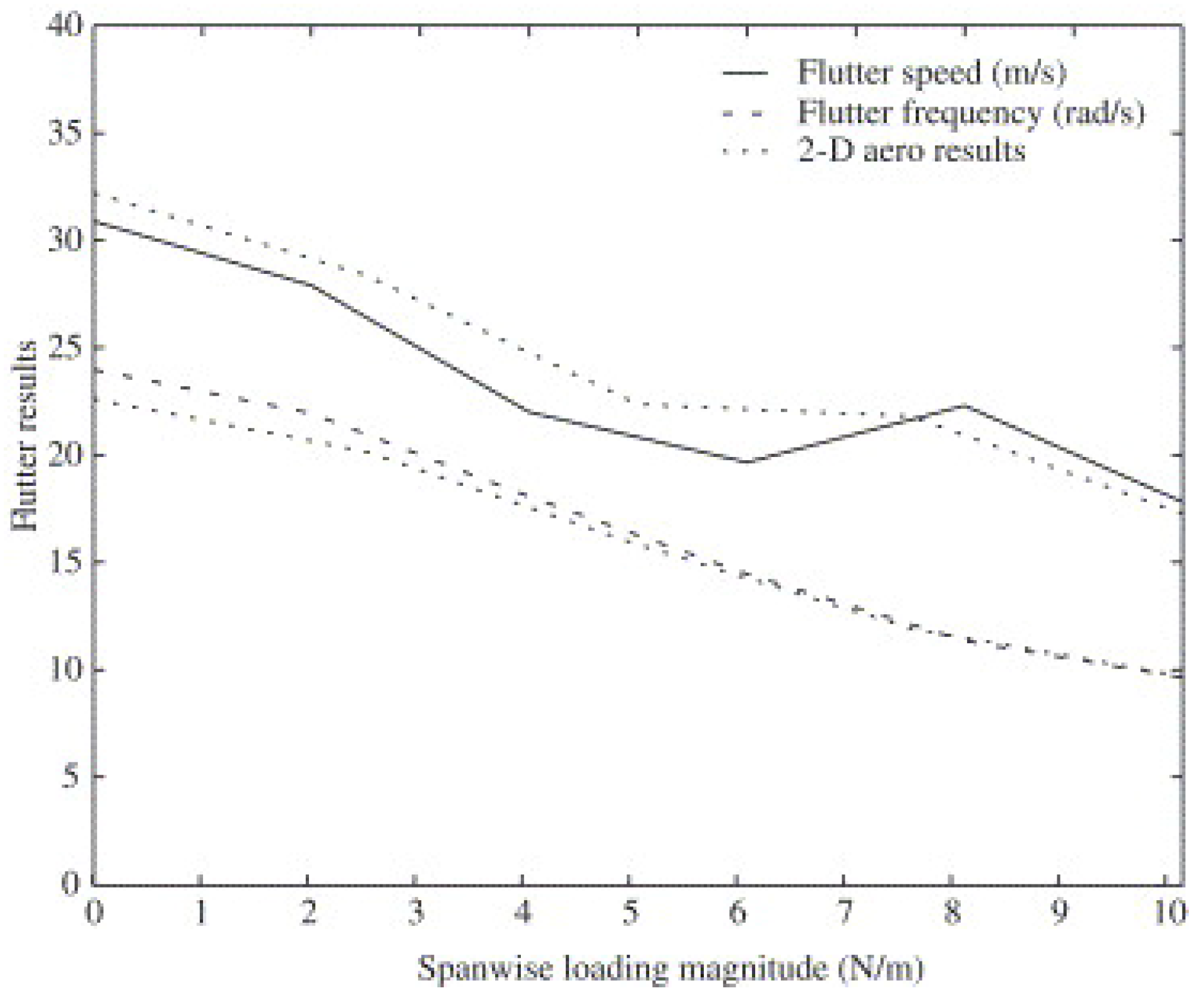
The obtained results show that among fuselage characteristics, mass contributes the most to changes in flutter speed. Figure 2 shows how increase in fuselage mass increases the flutter speed. Richards et al. also investigated the structural geometry, and showed that between skin and flange thickness, the latter is more effective in increasing the flutter speed (Figure 3) [7].
On one hand, the aeroelastic analysis of the aircraft requires advanced aeroelastic theories to model the system behavior sufficiently accurate. On the other hand, design theories are required to understand, analyze, and predict the appropriate choice of geometry with allometric rules that unite the design of a wide range of aircraft.
Studies based on Constructal Law show that the evolution of airplane is not by chance and follows a certain rule. It was shown that their main components (fuselage, wings, engine) follow a certain size proportionality, regardless of the overall size of the aircraft [8,9]. The “constructal theory of design” [10,11] is used to analytically investigate the size effect of the airplane components. Reference [8] shows that engine mass is proportional to the body size, body size is proportional to fuel weight, and range of flight corresponds to body size. Furthermore, the constructal theory reveals that the scales provided for the human-made aircraft are analogous to animal organs and the whole animal [8,10,11]. For instance, the organs that constitute the motor system of the animal (muscles, heart, lung) are the counterparts of the engine of the aircraft. In biology, it is well known that the muscle mass, the heart mass, and the lung volume are empirically proportional to the animal body mass [10,11].
The presented review focuses on the engine as one of the key organs of the aircraft. Rather than investigating the changes in the external air flow due to engine geometry and location, the numerical studies here mainly deal with the structural effects of the engine placement, and explore the changes in the stress flow through the structure. In this paper design with the constructal theory is introduced, a brief introduction of the theory behind NATASHA (Nonlinear Aeroelastic Trim And Stability of Hale Aircraft) is presented, and its applications in modern aircraft design are explored. Engine placement, as one of the key aspects of aircraft design, is investigated in detail, and it is presented that proper engine placement could suppress the aeroelastic instabilities and postpone the flutter. The importance of including nonlinearities in design is discussed, and it is shown that the geometric nonlinearity could highly affect critical flutter speed and eventually the flight envelope.
2. Theory
2.1. Design
Constructal theory views design in nature as a universal (physics) phenomenon. It states that “For a finite-size flow system to persist in time (to live) its configuration must change in time so that it provides greater and greater access to its currents” [11]. Constructal theory uses physics to guide design process toward novel architecture. Furthermore, utilizing the same physical principles, it can scientifically predict the natural design, and not just by mimicking nature. Constructal theory describes how physical principles are the source of similar scaling laws emerged in inanimate (geophysical) and animate (biological) flow systems [10].
Reviewing the history of airplane design, through the lens of constructal theory reveals that airplanes, through their evolution, have obeyed theoretical allometric rules that unite them with birds and other animals [8,9]. Like a bird, an airplane consumes energy to travel through the air. The act of traveling could be viewed as moving the mass of all the organs (fuselage, engine, etc.) and overcoming all energy losses (friction) in the flow system. As the size of the plane increases, the size of its organs (ducts, heat exchangers, pipes, etc.) also increase. On one hand, larger flow structures impose a smaller resistance to the flow, and consequently, fuel penalty due to friction becomes smaller. On the other hand, larger organs mean a heavier structure and more fuel consumption. This conflict emphasizes the importance of the organ size, that the organ should have a finite characteristic size which is just right for that particular vehicle [8,9].
Figure 4 shows evidence of the organ size trade off, during the evolution of airplanes an approximate proportionality has emerged between the mass of the heat engine and the mass of the whole aircraft (for engine data, see [8], Table 1), same correspondence exists also between wing and fuselage ratio. It is important to understand the physics behind the design, because if the law that captures the good design changes, and the choices that a large group of designers made are known, then the evolutionary direction is seen; and design can be better, faster, and more economical [9]. At a higher level, the Constructal law defines life and death as a physical principle and provides a very optimistic view of evolution of animate and inanimate systems [12].
2.2. Structural Model, Nonlinear Composite Beam
HALE aircraft structure could experience large deformations, even under static aeroelastic loads. Therefore, the aircraft configuration would be significantly different from the initial undeformed shape, and the beam-like wings would become highly curved during flight. The curvature changes the effective bending-torsion coupling of the beam, and consequently its aeroelastic characteristics. As a result, it becomes necessary to analyze the structure in a geometrically exact manner [13,14]. To address this key challenge in structural modeling of a HALE aircraft, Hodges used an intrinsic approach to developing nonlinear structural and dynamic formulation to describe behavior of initially curved/twisted beams with composite sections [13]. Over the past 20 years, this formulation has been widely used by Hodges and his team at Georgia Institute of Technology to investigate different aspects of HALE aircraft’s flight characteristics [5,15,16,17,18].
Equations (1)–(4) show the compact matrix form of the structural and dynamic equations. These equations do not contain any approximations to the geometry of the deformed beam, and they only use generalized strain variables to avoid singularities due to finite rotations [13,17].
Considering the representation of the deformed beam frame in Figure 5, Equation (1) describes the geometrically exact beam dynamics in a moving frame. Equations (2) and (3) describe the constitutive relations linking the generalized strains and momentum to stress and moments resultants, and frame velocities. Finally Equation (4) shows the dependence of the velocities and strains [13,17]. The presented system is a complete set of partial differential equations where the maximum order of differentiation is one, and the maximum degree of nonlinearity is equal to two [19].
In this system, forces and moments acting on the beam cross section are respectively presented by and . The same cross section’s linear and angular velocities are identified by and , and and are column matrices of cross-sectional linear and angular momentum. All the parameters with subscript are measured in the deformed frame. The cross-sectional properties are presented by 3 × 3 flexibility matrices (R, S, and T) and inertial matrix (I). is the mass per unit length, and shows the position coordinates of the cross-sectional mass center with respect to the reference line. Note that the tilde notation denotes the antisymmetric 3 × 3 matrix associated with the column matrix over which the tilde is placed; denotes the partial derivative with respect to time; and denotes the partial derivative with respect to the axial coordinate, [19].
The resulting equations are very similar to Euler’s dynamic equations of a rigid body, but the variational approach is taken to derive them links the Newtonian and energy-based methods, which is ideal for a finite element analysis scheme [13]. Later, Hodges et al. developed a finite element discretization explicitly based on the weak form of the geometrically exact intrinsic equilibrium. They presented the formulation for steady-state deformation as a set of nonlinear algebraic equations and used a generalized eigenvalue method to study the free vibrations about the steady state condition. The obtained results were validated against experimental data [15].
2.3. Aerodynamic Model, Finite-State Induced Flow
Following the same guideline in choosing the structural model, accommodating large deflections and nonlinear effects, the finite state aerodynamic model presented by Peters et al. [20] is utilized to obtain the aerodynamic loads acting on the structure. This model is a two-dimensional finite state presentation of an incompressible, inviscid flow around a thin airfoil. It uses known airfoil parameters, takes into account large motions of the structure, and captures the effects induced flow in the wake and apparent mass [20]. The lift, drag and pitching moment at the quarter-chord are given by:
where
and , are the measure numbers of and is the angle of flap deflection.
3. NATASHA, Nonlinear Aeroelastic Trim And Stability of Hale Aircraft
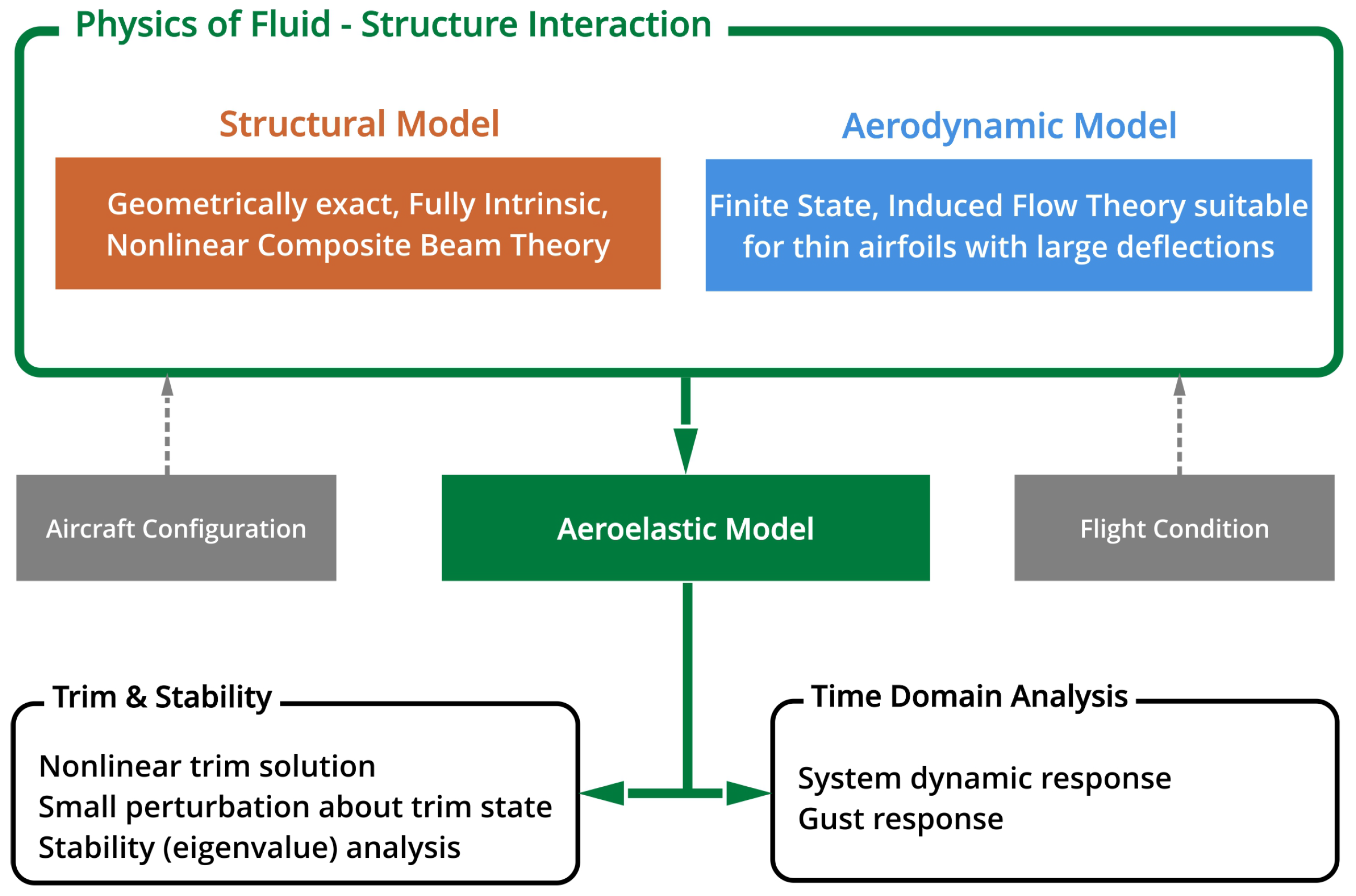
The computational structural and fluid dynamic theories presented in Section 2.2 and Section 2.3 are combined in a discretized system of equations to study flight dynamics of highly flexible aircraft [2]. This system takes advantage of Hodges’ nonlinear beam theory [17] along with the finite state induced flow model of Peters et al. [20].
The governing equations for the structural model are geometrically exact, fully intrinsic, and could analyze the dynamical behavior of a general anisotropic beam with non-uniform, twisted or curved structure undergoing large deformations. Although the aerodynamic model does not consider the 3D effects associated with the wing tip, published data proves this theory to be capable of producing accurate approximations of aerodynamic loads acting on high-aspect-ratio wings [3,20,21]. NATASHA is a computer program designed to solve the discretized nonlinear ordinary differential equations [2]. First, it generates a linearized system about a steady state of motion, then solves the calculated trim solution using Newton-Raphson or similar procedures (see Figure 6). The linearized system results in a standard eigenvalue problem, which NATASHA uses to assess stability [2].
NATASHA’s performance was validated with well established theoretical solutions and computer codes as DYMORE and RCAS [22,23,24,25,26]. Mardanpour et al. considered the classical cantilever wing model of Goland [27] and verified NATASHA for the behavior of the eigenvalues as well as the effect of sweep on divergence and flutter characteristics [3,21].
4. Results and Discussion
In a flying wing configuration, the engine is one of the key sources of structural and inertial loads. Consequently, its location could highly affect flutter characteristics of the aircraft. The topic was extensively explored by Mardanpour et al. [3,21,28], they studied the effect of engine placement on flutter behavior of a flying wing similar to Horten IV (for model data see [21], Tables 1–3). Each engine was modeled as a rigid body with a mass, an inertia matrix, a value of angular momentum, and a thrust vector represented as a follower force. Figure 7a shows the schematic view of the flying wing with two engines. Engine location is measured along the wing span, and the results show that the maximum and minimum flutter speeds occur for engine placement at 60% of the span and wing tip, respectively. Figure 7b shows the contour of flutter when engine is placed at 65% of the span, but free to move on plane. In this case, placing the engine forward of the elastic axis results in higher flutter speeds [21].
Similar analysis for an aircraft with multiple engines (Figure 8a) shows that when the first engine is located at 50%–70% of the span and second engine is at 80%, maximum flutter speed will be obtained [28]. Figure 8b shows the normalized flutter speed contour for different engine locations on plane when and [28].
Different combinations of engine placement were evaluated for different flight conditions. For instance, it was shown if first and second engines are respectively placed at 10% span and 50 to 70% span, it would be easier to trim the aircraft when the outboard engine fails [28].
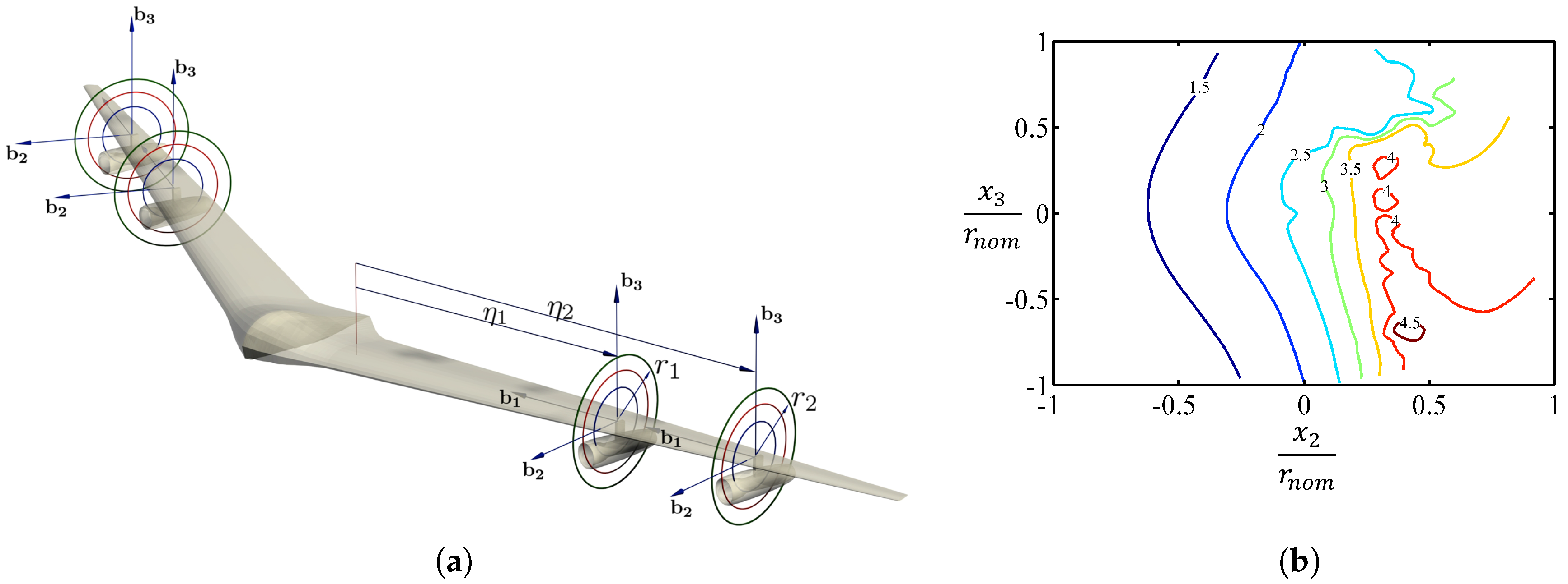
Figure 9a,b show the schematic view of a single wing and normalized flutter speed contours for different engine locations. Stability analysis with and without gravity, both show that engine placement at 60% to 80% span forward of the elastic axis increase the flutter speed more than three times of the base model (clean wing without engine and gravity effects, for model data, see [3], Tables 1 and 2). It should be noted analysis without considering the effect of gravity, was not capable of predicting the drop of flutter speed at 35 to 55% span.
Taking one step further than stability analysis, the dynamic response of a high-aspect-ratio wing accompanying a lightweight engine (JetCat SP5) was investigated, with and without considering the effect of gravity [3]. It was assumed that the engine is working at cruise condition, it can be moved along the span, and it has an adjustable offset from the elastic axis.
The engine was placed at 25%, 50%, 75% span, and at the tip of the wing. The offset from the elastic axis was measured using polar coordinates with , where r is the radial offset from the elastic axis, normalized by chord, and presents the angle between r and axis. Rectangular pulse and ramp fuel profiles were used to describe the transient behavior of the engine, and dynamic response was calculated using NATASHA, where a second-order, central-difference, time marching algorithm was applied [3]. Results showed for certain engine placements, even though the airspeed is below flutter, the wing could undergo LCO due to impulse, Figure 10. For instance, a wing with engine placed at , , and , and air speed below critical flutter speed experiences stable LCO when affected by rectangular pulse (Figure 11).
Furthermore, Mardanpour et al. studied the effects of engine placement on nonlinear aeroelastic gust response of a very flexible high-aspect-ratio wing, Figure 9a. They moved the engine location along the wing span, and exposed each configuration to an unsteady gust load, and solved system dynamics in the time domain. Comparison of the time domain results for the effects of the gust excitation and the frequency domain results for flutter speed indicate that the engine placement in the regions with maximum flutter speed has the potential to suppress the instabilities due to gust. For instance, gust acting on a wing with engine placement at 25% and 50% span without any offset will lead to limit cycle oscillations, Figure 12a,b. Conversly, engine placement at 75% span with offset forward of the elastic axis could suppress the oscillations to the gust load, Figure 12c [29].
The flexible structure of HALE aircraft, subjected to aerodynamic loads or jet thrust, can undergo large deformations and consequently form configurations considerably different from the undeformed aircraft. The direction of loads, such as engine thrust, depends on the geometry of the structure, and it changes as the structure deforms. Therefore, engine thrust could be categorized as a follower force. Follower forces are non-conservative forces which could induce instability on flexible aeroelastic systems.
Fazelzadeh et al. studied the effect of lateral concentrated follower force acting on a high-aspect-ratio beam [30,31], and their results showed a continuous decrease in flutter speed with the increase in the follower force. Mardanpour et al. employed the geometrically exact and fully intrinsic beam theory to investigate the effect of distributed follower forces. Their study considered all possible spatial distributions of the follower forces, and NATASHA was used to obtain the Hopf bifurcation point and behavior of the eigenvalues at pre- and post-instability [32]. Taking advantage of the capabilities of the nonlinear composite beam theory, they also explored the possibility of suppressing structure instability by applying a pretwist on the beam, Figure 13.
Figure 14 shows the normalized real part of the eigenvalues vs. normalized distributed follower forces for a model high-aspect ratio beam (for model data see [32], Table 2), and it could be observed that an increase in beam’s pre-twist could postpone flutter. In this figure, beam’s normalized pre-twist is presented with . is the ratio between torsional and out-of-plane bending flexibility, shows the ratio of out-of-plane and in-plane bending flexibility. and are the angles between follower force and , and follower force and , respectively. Critical follower force values for different were also calculated, and results showed a considerable sudden increase in critical force values, for normalizing pre-twist values about 3 (which means that the beam’s tip experiences an approximately 180-degree rotation), Figure 15.
The time domain response of the beam to a follower force excitation was investigated [32]. The obtained results indicate that as the pre-twist increases, the amplitude of the oscillation and the velocity of the beam tip are also affected significantly. The beam experiencing a follower force with magnitude smaller than its critical value undergoes oscillations with small amplitude. However, when the follower force reaches its critical value, the beam experiences large oscillations from a small excitation, and the magnitude of the oscillations of a beam with pre-twist is less than that of a beam without pre-twist. For example, Figure 16 shows how the amplitude of beam tip oscillations could be reduced by increasing the beam pre-twist [32].
Furthermore, a high-aspect-ratio beam under a partially distributed follower force, Figure 13b. They showed that as the partially distributed force moves toward the tip of them the critical follower force decrease. Furthermore, the value of the critical force is highly affected by the ratio between in-plane bending and torsional stiffness [32].
5. Concluding Remarks and Future Works
Studying the effects of engine placement on frequency and time domain responses of a very flexible aero-structure reveals that when the engine is located at 50–70% span, the structure tends to flutter at a higher speed, see Table 1 [3]. It is noteworthy that the natural vibration modes of a clear wing (without engine) shows that the same area along the wing span (50–70%) corresponds to the minimum kinetic energy zone [14]. Kinetic energy is at its minimum, where the potential energy (i.e., the strain energy) reaches its maximum. In other words, placing the engines at locations where the natural modes of structure experience the largest strains (and consequently the largest stresses) leads to a better aeroelastic performance, and extends the safe flight envelope.
To fully understand how engine placement affects the aircraft performance, the physics governing the response of the structure needs to be explored. Constructal theory, as a physics based theory of design, states that the better design occurs when greater and greater access is provided to the currents that flow through the system [33].
For a flexible body under tension or compression through out its volume, internal flow of stress appears, and the structure deforms to accommodate better flow of stress. Constructal theory explains that similar to any flow system, flow strangulation is not desired [33]. Engine placement at locations where maximum stress appears leads to a configuration with less stress strangulation and smoother flow of stress, hence the better design emerges. This avenue worth further and more detailed investigation to obtain the stress flow fields through the structure (p. 409 in References [11,33]).
Reviewing aircraft design through constructal theory reveals very important scaling laws, and it proves that the evolution of airplanes and helicopters follow the same physics as the evolution of flyers, runners, and swimmers, which is governed by the Constructal Law. These scaling laws provide a powerful tool to understand the physics behind different designs, and provides insight to scale up/down a certain design.
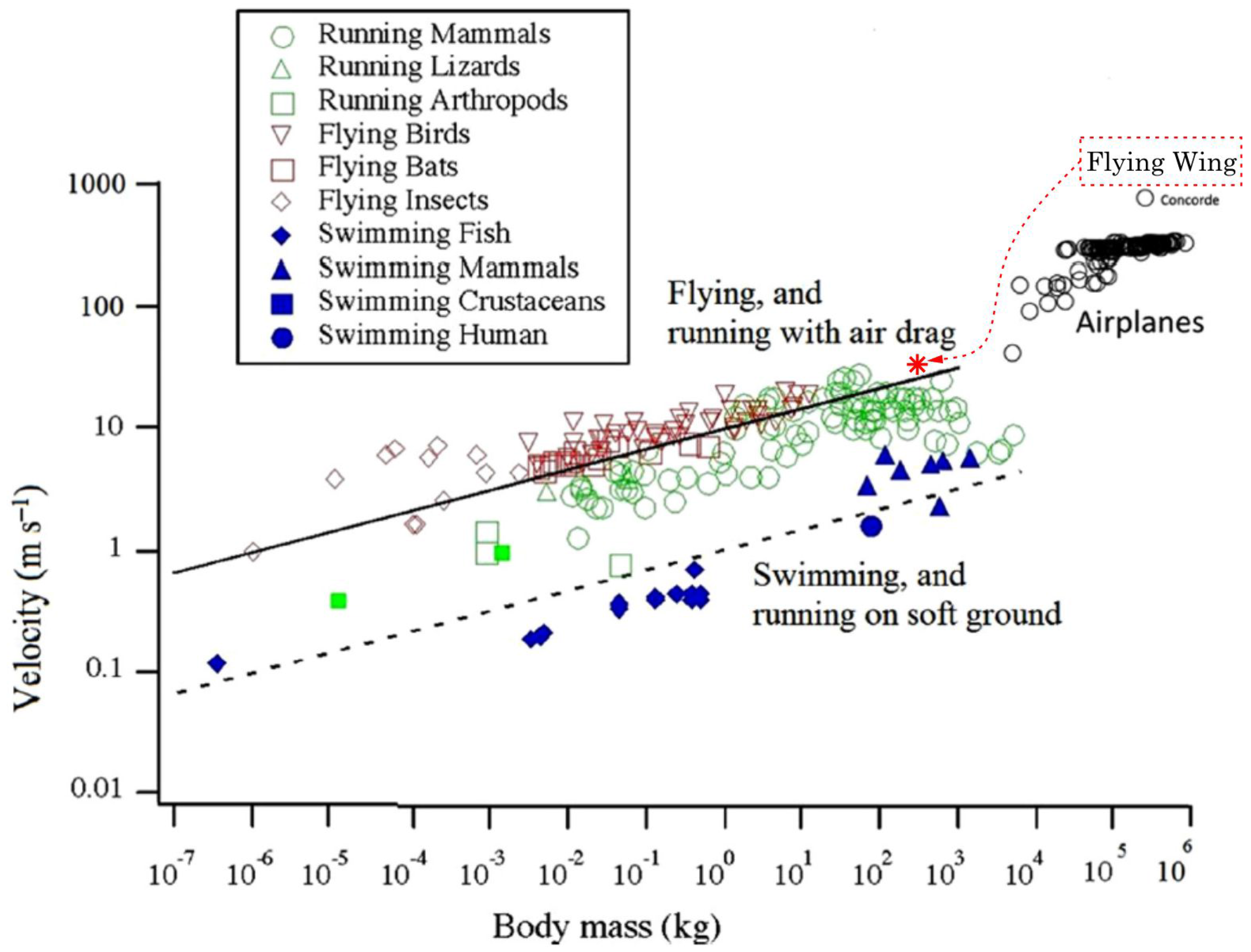
Flutter analysis of the flying-wing-aircraft presented in [7], shows the dependency of the maximum safe flight speed to the total body size. This data compared with the findings of Bejan [8] regarding the dependency of flight speed and body mass, shows an expected correspondence. Figure 17 shows the characteristic speed of all the bodies that fly, run and swim, and it could be seen that the particular flying-wing aircraft mentioned in [7] follows the same allometric rules as other fliers.
To reach to a better design, in addition to the guidelines of the constructal law, a structural theory, which takes into account effects of the geometric nonlinearities is crucial. The presented studies, and results, indicate that the flight dynamic characteristics of the deformed aircraft are completely different as compared to a rigid aircraft, and due to geometric nonlinearities, the employed trim solution should take into account the large deformations due to static aeroelastic forces. It should be noted that linear stability analysis could only estimate the response of the system to small disturbances, and it does not provide an accurate model for system response to large excitation.
Acknowledgments
Pezhman Mardanpour’s research is supported by Air Force Office of Scientific Research (AFOSR) and National Science Foundation (NSF).
Author Contributions
Pezhman Mardanpour conducted the analysis; Pezhman Mardanpour and Siavash Rastkar analyzed the data; Siavash Rastkar compiled the review and articulated the manuscript.
Conflicts of Interest
The authors declare no conflict of interest.
References
- Patil, M.J.; Hodges, D.H. On the importance of aerodynamic and structural geometrical nonlinearities in aeroelastic behavior of high-aspect-ratio wings. J. Fluids Struct. 2004, 19, 905–915. [Google Scholar] [CrossRef]
- Patil, M.J.; Hodges, D.H. Flight dynamics of highly flexible flying wings. J. Aircr. 2006, 43, 1790–1799. [Google Scholar] [CrossRef]
- Mardanpour, P.; Hodges, D.H.; Rezvani, R. Nonlinear aeroelasticity of high-aspect-ratio wings excited by time-dependent thrust. Nonlinear Dyn. 2014, 75, 475–500. [Google Scholar] [CrossRef]
- Drela, M. Integrated simulation model for preliminary aerodynamic, structural, and control-law design of aircraft. In Proceedings of the 40th Structures, Structural Dynamics, and Materials Conference and Exhibit, St. Louis, MO, USA, 12–15 April 1999; p. 1394. [Google Scholar]
- Raghavan, B.; Patil, M. Flight dynamics of high aspect-ratio flying wings. In Proceedings of the AIAA Atmospheric Flight Mechanics Conference and Exhibit, Keystone, CO, USA, 21–24 August 2006; p. 6135. [Google Scholar]
- Shearer, C.M.; Cesnik, C.E. Nonlinear flight dynamics of very flexible aircraft. J. Aircr. 2007, 44, 1528–1545. [Google Scholar] [CrossRef]
- Richards, P.W.; Yao, Y.; Herd, R.A.; Hodges, D.H.; Mardanpour, P. Effect of inertial and constitutive properties on body-freedom flutter for flying wings. J. Aircr. 2016, 53, 756–767. [Google Scholar] [CrossRef]
- Bejan, A.; Charles, J.; Lorente, S. The evolution of airplanes. J. Appl. Phys. 2014, 116, 044901. [Google Scholar] [CrossRef]
- Bejan, A.; Charles, J.; Lorente, S.; Dowell, E. Evolution of airplanes, and what price speed? AIAA J. 2016, 54, 1120–1123. [Google Scholar] [CrossRef]
- Bejan, A.; Lorente, S. The constructal law of design and evolution in nature. Philos. Trans. R. Soc. B Biol. Sci. 2010, 365, 1335–1347. [Google Scholar] [CrossRef] [PubMed]
- Bejan, A.; Lorente, S. Design with constructal theory. In Proceedings of the Shape and Thermodynamics, International Workshop Florence 2008, Florence, Italy, 25–26 September 2008. [Google Scholar]
- Bejan, A. The Physics of Life: The Evolution of Everything; St. Martin’s Press: New York, NY, USA, 2016; ISBN-13: 978-1250078827. [Google Scholar]
- Hodges, D.H. A mixed variational formulation based on exact intrinsic equations for dynamics of moving beams. Int. J. Solids Struct. 1990, 26, 1253–1273. [Google Scholar] [CrossRef]
- Mardanpour, P.; Hodges, D.H. On the importance of nonlinear aeroelasticity and energy efficiency in design of flying wing aircraft. Adv. Aerosp. Eng. 2015, 2015, 613962. [Google Scholar] [CrossRef]
- Hodges, D.H.; Shang, X.; Cesnik, C.E. Finite element solution of nonlinear intrinsic equations for curved composite beams. J. Am. Helicopter Soc. 1996, 41, 313–321. [Google Scholar] [CrossRef]
- Yu, W.; Volovoi, V.V.; Hodges, D.H.; Hong, X. Validation of the variational asymptotic beam sectional analysis. AIAA J. 2002, 40, 2105–2112. [Google Scholar] [CrossRef]
- Hodges, D.H. Geometrically exact, intrinsic theory for dynamics of curved and twisted anisotropic beams. AIAA J. 2003, 41, 1131–1137. [Google Scholar] [CrossRef]
- Chang, C.S.; Hodges, D.H.; Patil, M.J. Flight dynamics of highly flexible aircraft. J. Aircr. 2008, 45, 538–545. [Google Scholar] [CrossRef]
- Hodges, D.H. Nonlinear composite beam theory. Prog. Astronaut. Aeronaut. 2006, 213, 304. [Google Scholar]
- Peters, D.A.; Karunamoorthy, S.; Cao, W.M. Finite state induced flow models. I—Two-dimensional thin airfoil. J. Aircr. 1995, 32, 313–322. [Google Scholar] [CrossRef]
- Mardanpour, P.; Hodges, D.H.; Neuhart, R.; Graybeal, N. Engine placement effect on nonlinear trim and stability of flying wing aircraft. J. Aircr. 2013, 50, 1716–1725. [Google Scholar] [CrossRef]
- Timoshenko, S.P.; Gere, J.M. Theory of elastic stability. In Dover Civil and Mechanical Engineering; McGrawHill-Kogakusha Ltd, Tokyo: Tokyo, Japan, 1961; ISBN-13: 978-0486472072. [Google Scholar]
- Simitses, G.J.; Hodges, D.H. Fundamentals of Structural Stability; Butterworth-Heinemann: Oxford, UK, 2006. [Google Scholar]
- Bauchau, O.A.; Kang, N. A multibody formulation for helicopter structural dynamic analysis. J. Am. Helicopter Soc. 1993, 38, 3–14. [Google Scholar]
- Bauchau, O.A. Computational schemes for flexible, nonlinear multi-body systems. Multibody Syst. Dyn. 1998, 2, 169–225. [Google Scholar] [CrossRef]
- Saberi, H.; Khoshlahjeh, M.; Ormiston, R.A.; Rutkowski, M.J. Overview of RCAS and application to advanced rotorcraft problems. In Proceedings of the American Helicopter Society 4th Decennial Specialists’ Conference on Aeromechanics, San Francisco, CA, USA, 21–23 January 2004. [Google Scholar]
- Goland, M.; Luke, Y. The flutter of a uniform wing with tip weights. J. Appl. Mech. 1948, 15, 13–20. [Google Scholar]
- Mardanpour, P.; Richards, P.W.; Nabipour, O.; Hodges, D.H. Effect of multiple engine placement on aeroelastic trim and stability of flying wing aircraft. J. Fluids Struct. 2014, 44, 67–86. [Google Scholar] [CrossRef]
- Mardanpour, P.; Izadpanahi, E.; Rastkar, S.; Hodges, D.H. Effects of engine placement on nonlinear aeroelastic gust response of high-aspect-ratio wings. In Proceedings of the AIAA Modeling and Simulation Technologies Conference, Denver, CO, USA, 5–9 June 2017; p. 576. [Google Scholar]
- Fazelzadeh, S.; Mazidi, A.; Kalantari, H. Bending-torsional flutter of wings with an attached mass subjected to a follower force. J. Sound Vib. 2009, 323, 148–162. [Google Scholar] [CrossRef]
- Fazelzadeh, S.; Mazidi, A. Nonlinear aeroelastic analysis of bending-torsion wings subjected to a transverse follower force. J. Comput. Nonlinear Dyn. 2011, 6, 031016. [Google Scholar] [CrossRef]
- Mardanpour, P.; Izadpanahi, E.; Rastkar, S.; Fazelzadeh, S.A.; Hodges, D.H. Geometrically-exact, fully intrinsic analysis of pretwisted beams under distributed follower forces. In Proceedings of the 58th AIAA/ASCE/AHS/ASC Structures, Structural Dynamics, and Materials Conference, Grapevine, TX, USA, 9–13 January 2017; p. 1986. [Google Scholar]
- Bejan, A.; Lorente, S. Constructal law of design and evolution: Physics, biology, technology, and society. J. Appl. Phys. 2013, 113, 6. [Google Scholar] [CrossRef]
Figure 1.
The effect of geometric nonlinearities on flutter [1]. Reprinted from Patil, M.J.; Hodges, D.H. On the importance of aerodynamic and structural geometrical nonlinearities in aeroelastic behavior of high-aspect-ratio wings. J. Fluids Struct. 2004, 19, 905–915, with permission from Elsevier.

Figure 2.
Flutter speed and frequency as a function of fuselage mass factor [7].
Figure 2.
Flutter speed and frequency as a function of fuselage mass factor [7].
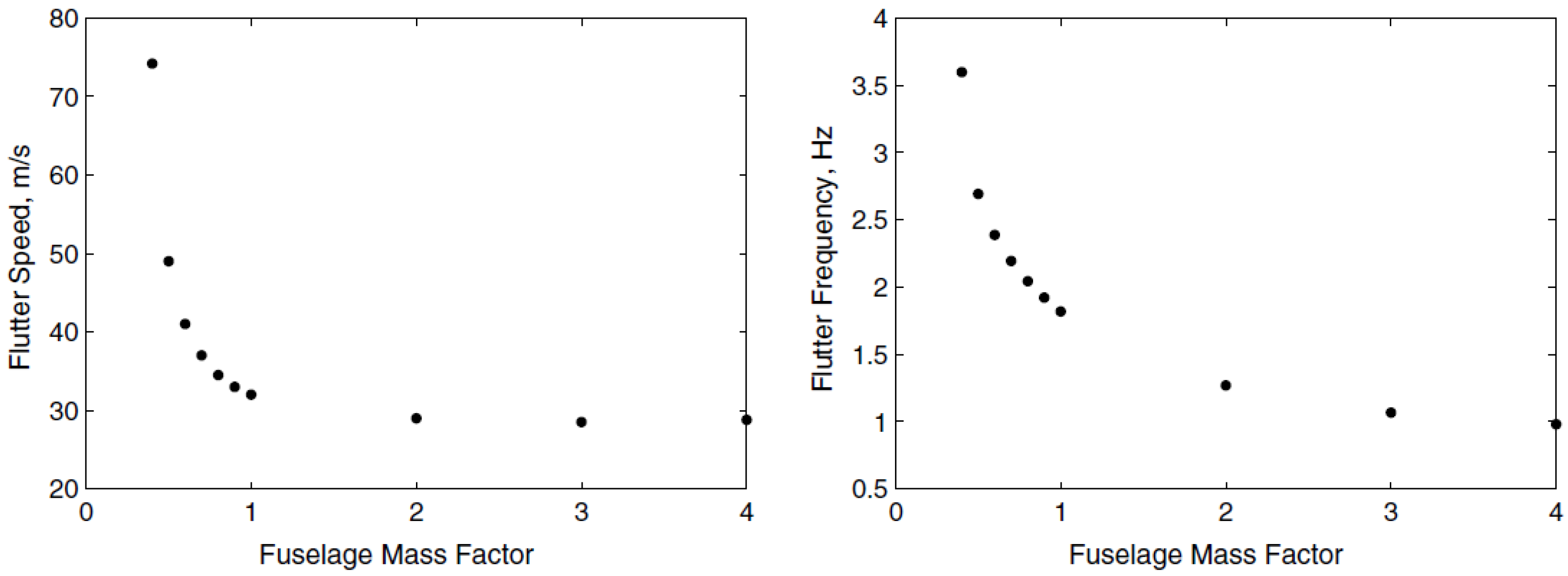
Figure 3.
Flutter speed and frequency as a function of flange thickness [7].
Figure 3.
Flutter speed and frequency as a function of flange thickness [7].
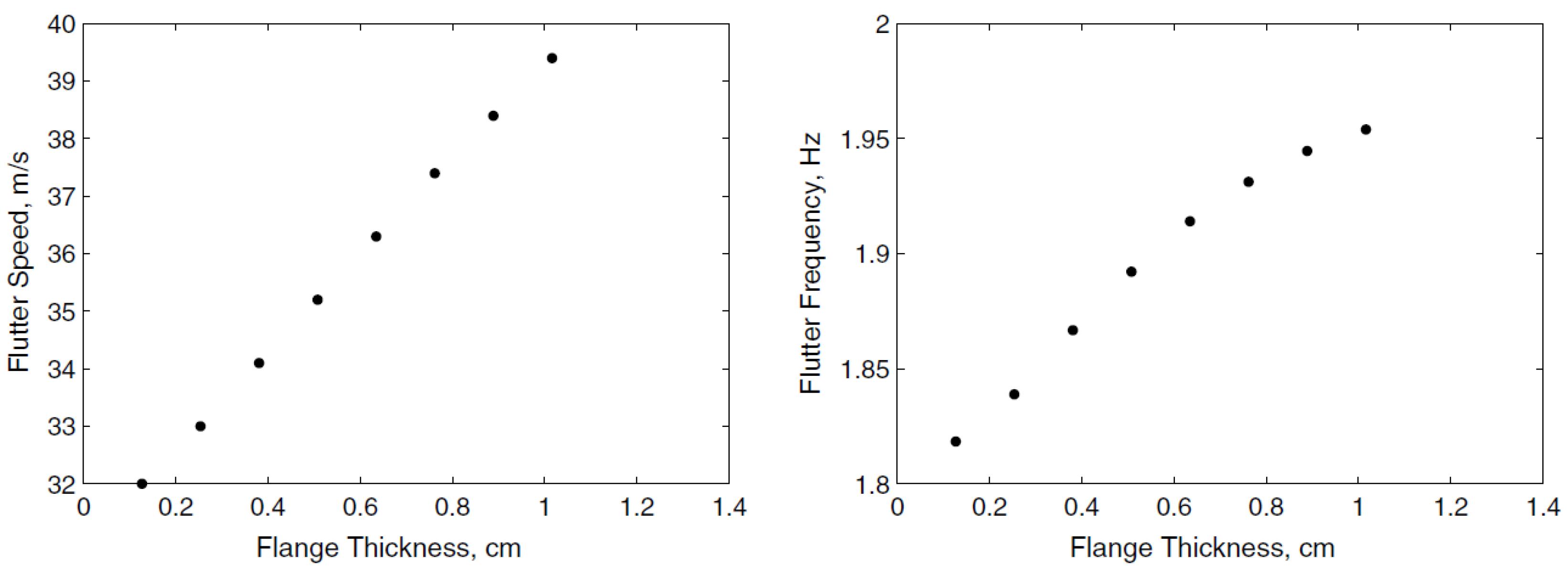
Figure 4.
(a) Engine size vs. airplane size during the evolution of airplanes; (b) Wing span vs. fueslage legth [8]. Reprinted from Bejan, A.; Charles, J.; Lorente, S. The evolution of airplanes. J. Appl. Phys. 2014, 116, 044901, with the permission of AIP publishing.
Figure 4.
(a) Engine size vs. airplane size during the evolution of airplanes; (b) Wing span vs. fueslage legth [8]. Reprinted from Bejan, A.; Charles, J.; Lorente, S. The evolution of airplanes. J. Appl. Phys. 2014, 116, 044901, with the permission of AIP publishing.
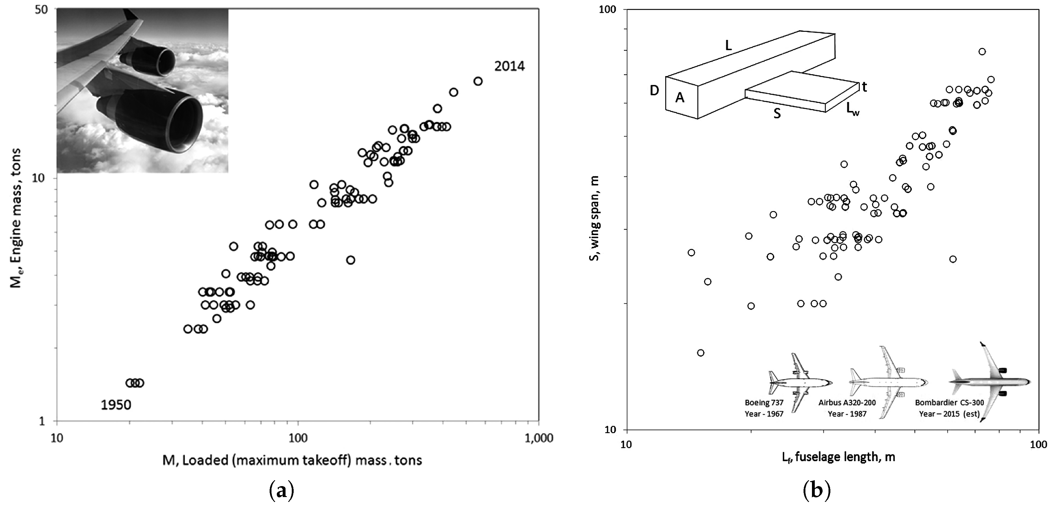
Figure 5.
Beam kinematics in deformed and undeformed states. The green color shows the undeformed section, red represents the deformed section without considering the warping effect, and the blue color shows the warping effect on the deformed section.
Figure 5.
Beam kinematics in deformed and undeformed states. The green color shows the undeformed section, red represents the deformed section without considering the warping effect, and the blue color shows the warping effect on the deformed section.
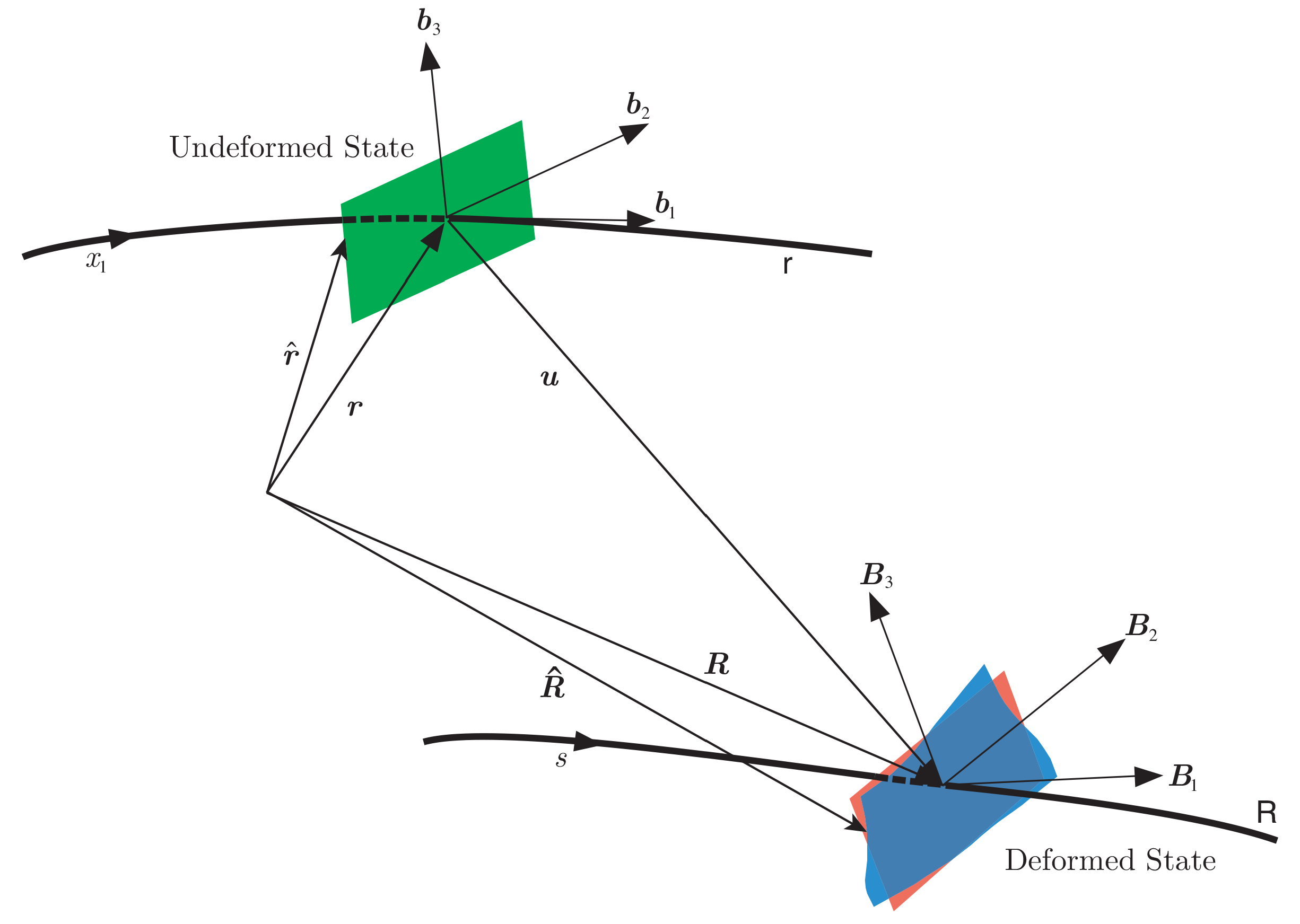
Figure 6.
Workflow of NATASHA.

Figure 7.
(a) Schematic view of the flying wing with two engines; (b) Normalized flutter speed contour for different engine locations on plane () [21].
Figure 7.
(a) Schematic view of the flying wing with two engines; (b) Normalized flutter speed contour for different engine locations on plane () [21].
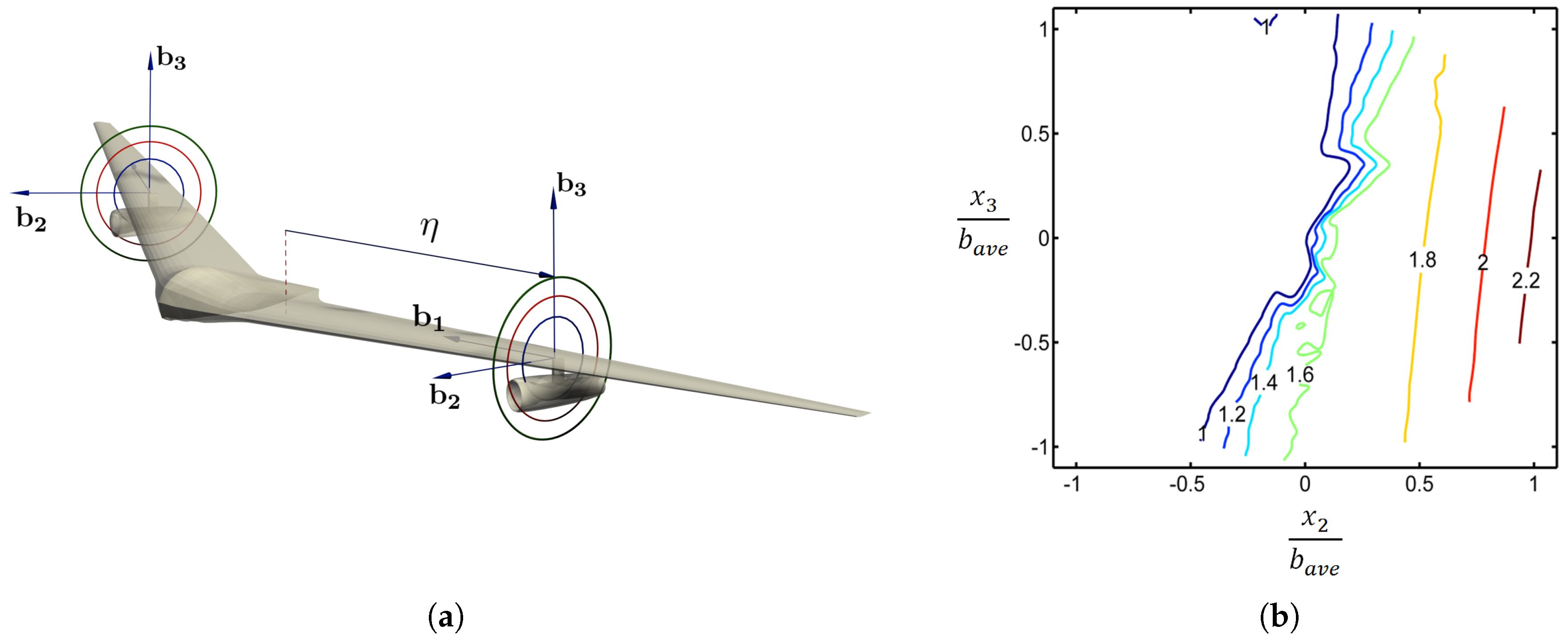
Figure 8.
(a) Schematic view of the flying wing with four engines; (b) Normalized flutter speed contour for different engine locations on plane ( and ) [28]. Reprinted from Mardanpour, P.; Richards, P.W.; Nabipour, O.; Hodges, D.H. Effect of multiple engine placement on aeroelastic trim and stability of flying wing aircraft. J. Fluids Struct. 2014, 44, 67–86, with permission from Elsevier.

Figure 9.
(a) Schematic view of the high-aspect-ratio wing with engine; (b) Normalized flutter speed contour for different engine locations on plane; considering gravity [3]. Reprinted from Mardanpour, P.; Hodges, D.H.; Rezvani, R. Nonlinear aeroelasticity of high-aspect-ratio wings excited by time-dependent thrust. Nonlinear Dyn. 2014, 75, 475–500, with the permission of Springer.
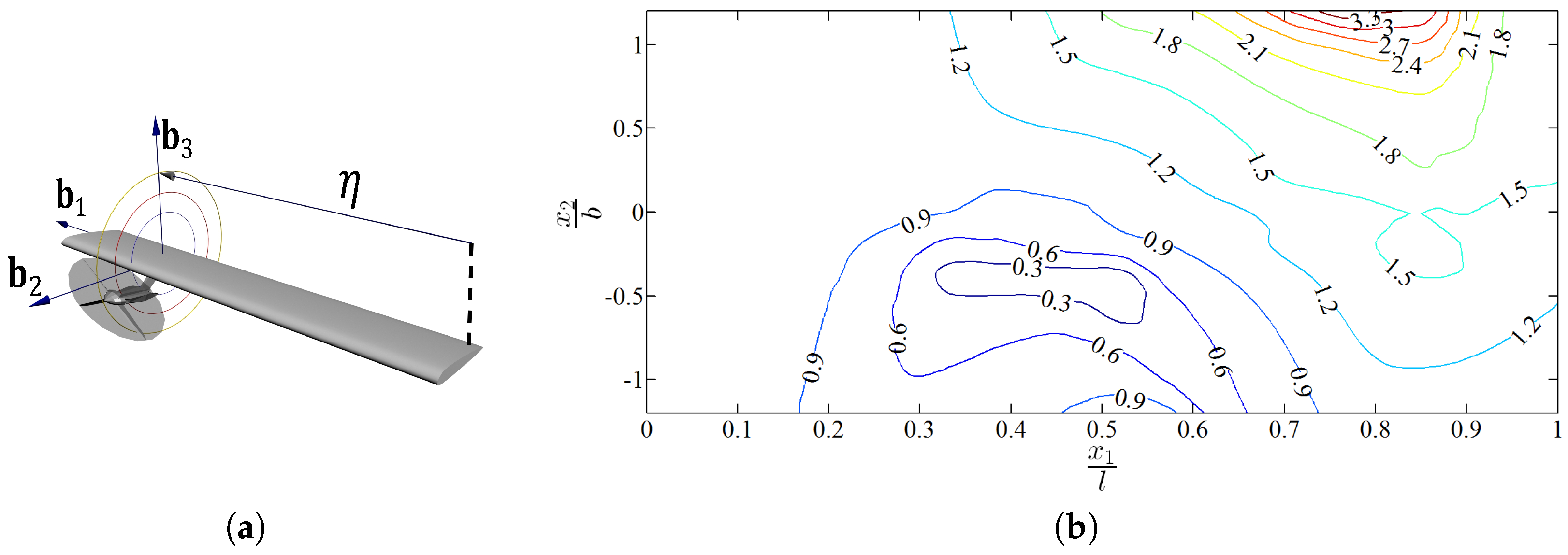
Figure 10.
Nonlinear dynamic response of a wing due to time dependent engine thrust for different engine placements. Green areas show the safe zone, where oscillations due to large excitation die out, orange areas show the engine locations leading to limit cycle oscillations above flutter speed, and red zones present the unsafe engine locations.
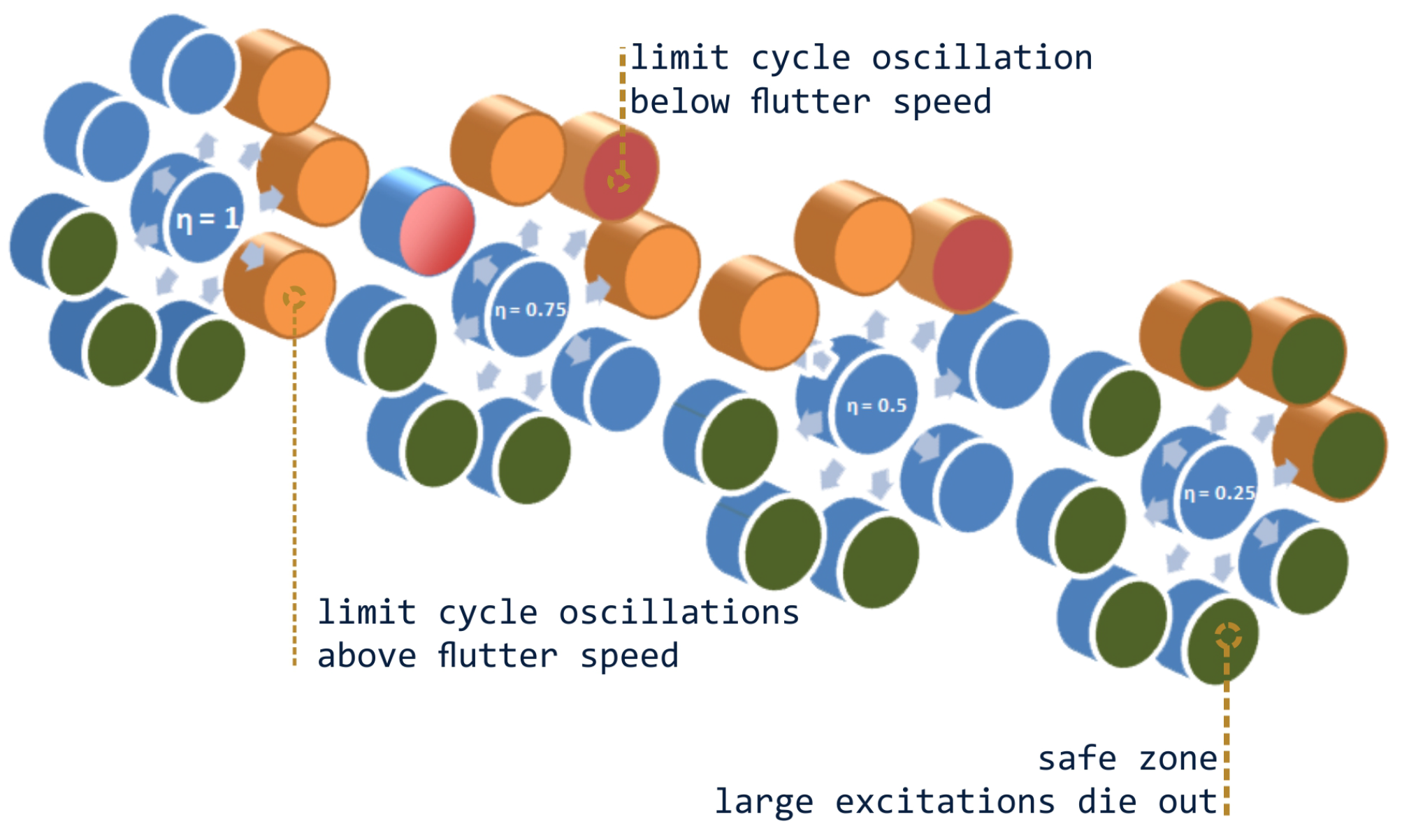
Figure 11.
(a) Wing tip position along vs. time; (b) Normalized wing tip position vs. velocity in direction; engine is placed at , , and [3]. Reprinted from Mardanpour, P.; Hodges, D.H.; Rezvani, R. Nonlinear aeroelasticity of high-aspect-ratio wings excited by time-dependent thrust. Nonlinear Dyn. 2014, 75, 475–500, with the permission of Springer.
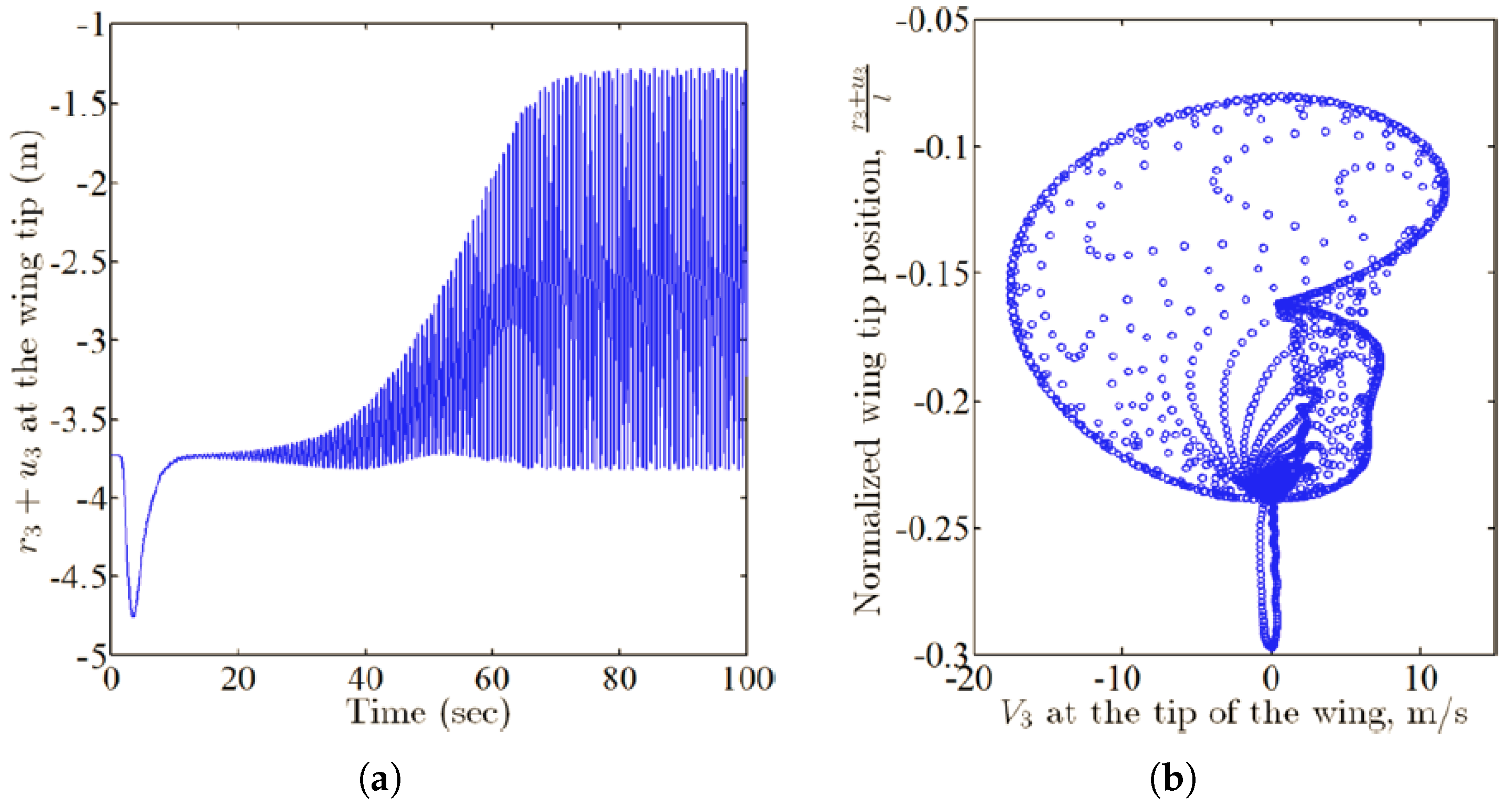
Figure 12.
Normalized wing tip position along vs. normalized time for engine placement at (a) and ; (b) and ; (c) and [29].
Figure 12.
Normalized wing tip position along vs. normalized time for engine placement at (a) and ; (b) and ; (c) and [29].
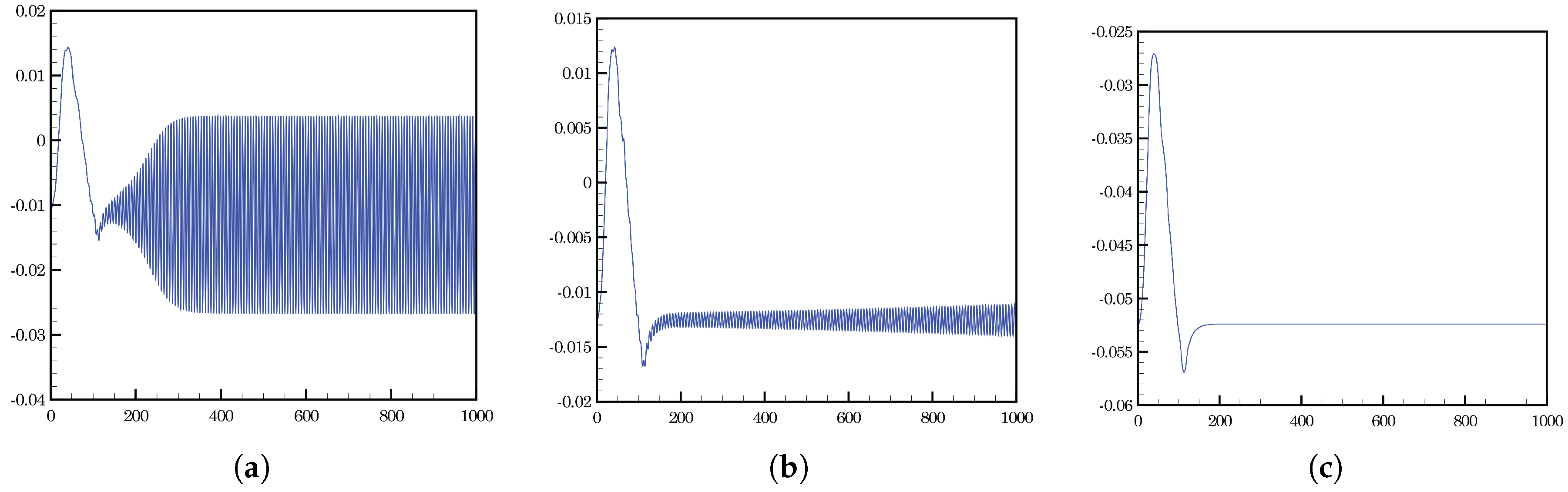
Figure 13.
Schematic 3D view of (a) Initially curved and twisted beam with ditributed follower force; (b) Beam with partially distributed follower force [32].
Figure 13.
Schematic 3D view of (a) Initially curved and twisted beam with ditributed follower force; (b) Beam with partially distributed follower force [32].
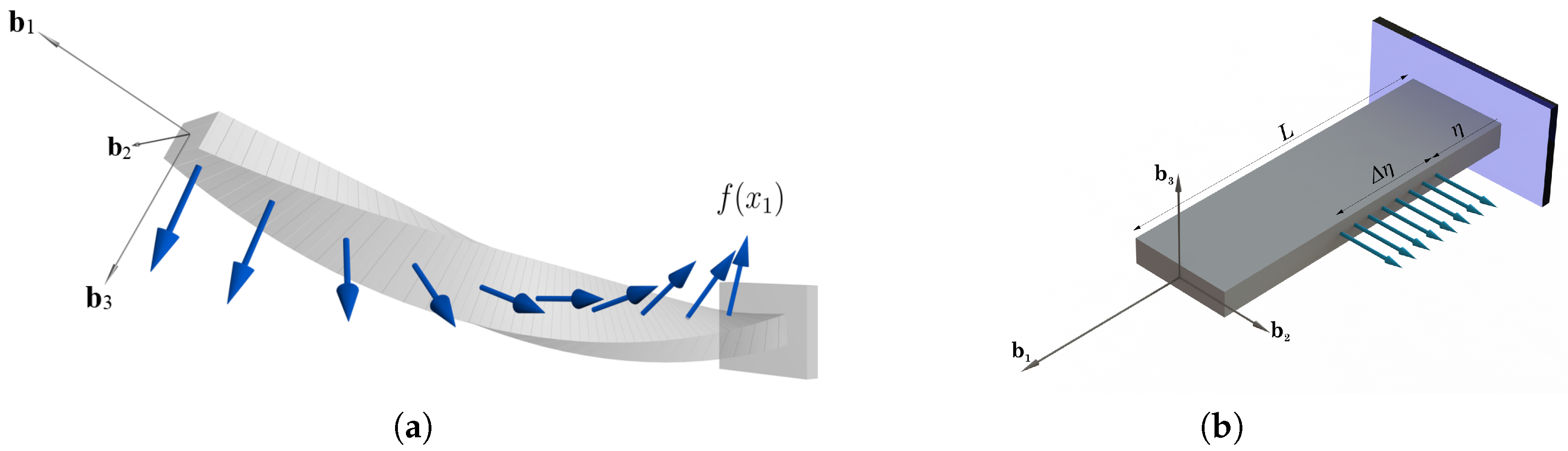
Figure 14.
Normalized real part of the eigenvalues vs. normalized distributed follower force [32].
Figure 14.
Normalized real part of the eigenvalues vs. normalized distributed follower force [32].
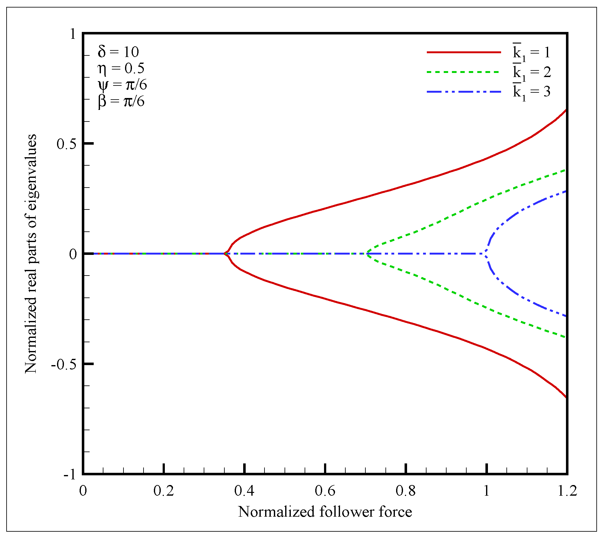
Figure 15.
Normalized critical follower forces () vs. for = 1, 2, 3; rad; and [32].
Figure 15.
Normalized critical follower forces () vs. for = 1, 2, 3; rad; and [32].
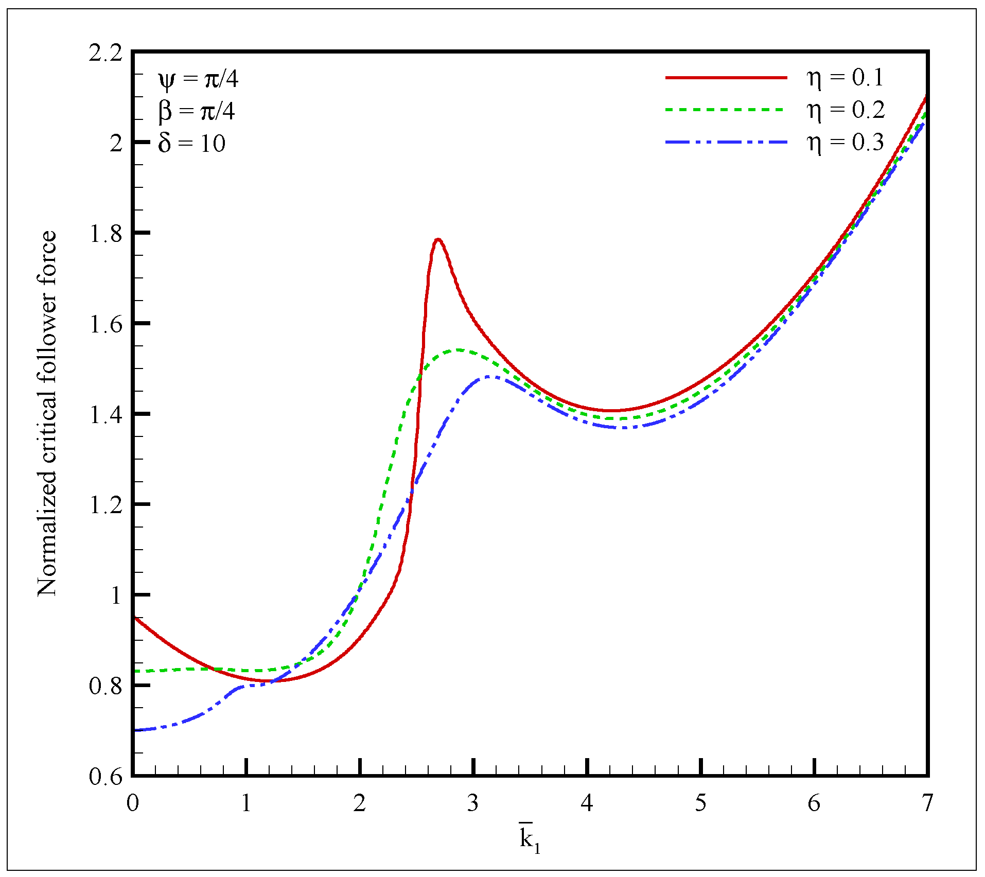
Figure 16.
Normalized magnitude of position vector in (a) ; (b) ; (c) directions vs. normalized time for = 0, 1, 2, 3; rad; ; and [32].
Figure 16.
Normalized magnitude of position vector in (a) ; (b) ; (c) directions vs. normalized time for = 0, 1, 2, 3; rad; ; and [32].
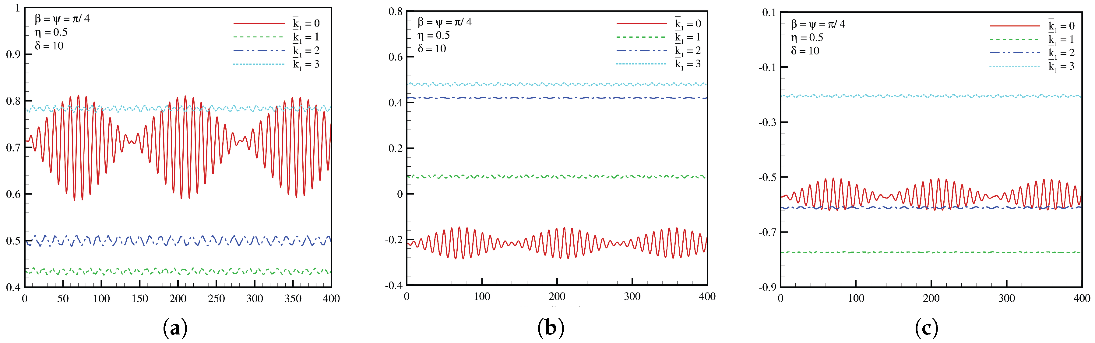
Figure 17.
The characteristic speed of all the bodies that fly, run and swim [8]. Reprinted from Bejan, A.; Charles, J.; Lorente, S. The evolution of airplanes. J. Appl. Phys. 2014, 116, 044901, with the permission of AIP publishing.
Figure 17.
The characteristic speed of all the bodies that fly, run and swim [8]. Reprinted from Bejan, A.; Charles, J.; Lorente, S. The evolution of airplanes. J. Appl. Phys. 2014, 116, 044901, with the permission of AIP publishing.


Table 1.
Best engine location obtained from stability and time domain analysis.
| Wing and Engine Configuration | Best Engine Location | |
|---|---|---|
| Stability Analysis | Time Domain Analysis | |
| Flying Wing with 2 Engines | 60% span | Not Available |
| Flying Wing with 4 Engines | 50–80% span | Not Available |
| Single Wing with 1 Engine | 60–80% span | 75% span |
© 2017 by the authors. Licensee MDPI, Basel, Switzerland. This article is an open access article distributed under the terms and conditions of the Creative Commons Attribution (CC BY) license (http://creativecommons.org/licenses/by/4.0/).
Share and Cite
MDPI and ACS Style
Mardanpour, P.; Rastkar, S. Constructal Theory and Aeroelastic Design of Flexible Flying Wing Aircraft. Aerospace 2017, 4, 35. https://doi.org/10.3390/aerospace4030035
AMA Style
Mardanpour P, Rastkar S. Constructal Theory and Aeroelastic Design of Flexible Flying Wing Aircraft. Aerospace. 2017; 4(3):35. https://doi.org/10.3390/aerospace4030035
Chicago/Turabian StyleMardanpour, Pezhman, and Siavash Rastkar. 2017. "Constructal Theory and Aeroelastic Design of Flexible Flying Wing Aircraft" Aerospace 4, no. 3: 35. https://doi.org/10.3390/aerospace4030035
Note that from the first issue of 2016, this journal uses article numbers instead of page numbers. See further details here.