Manufacturing Aspects of Creating Low-Curvature Panels for Prospective Civil Aircraft

 ,
,
Abstract
:
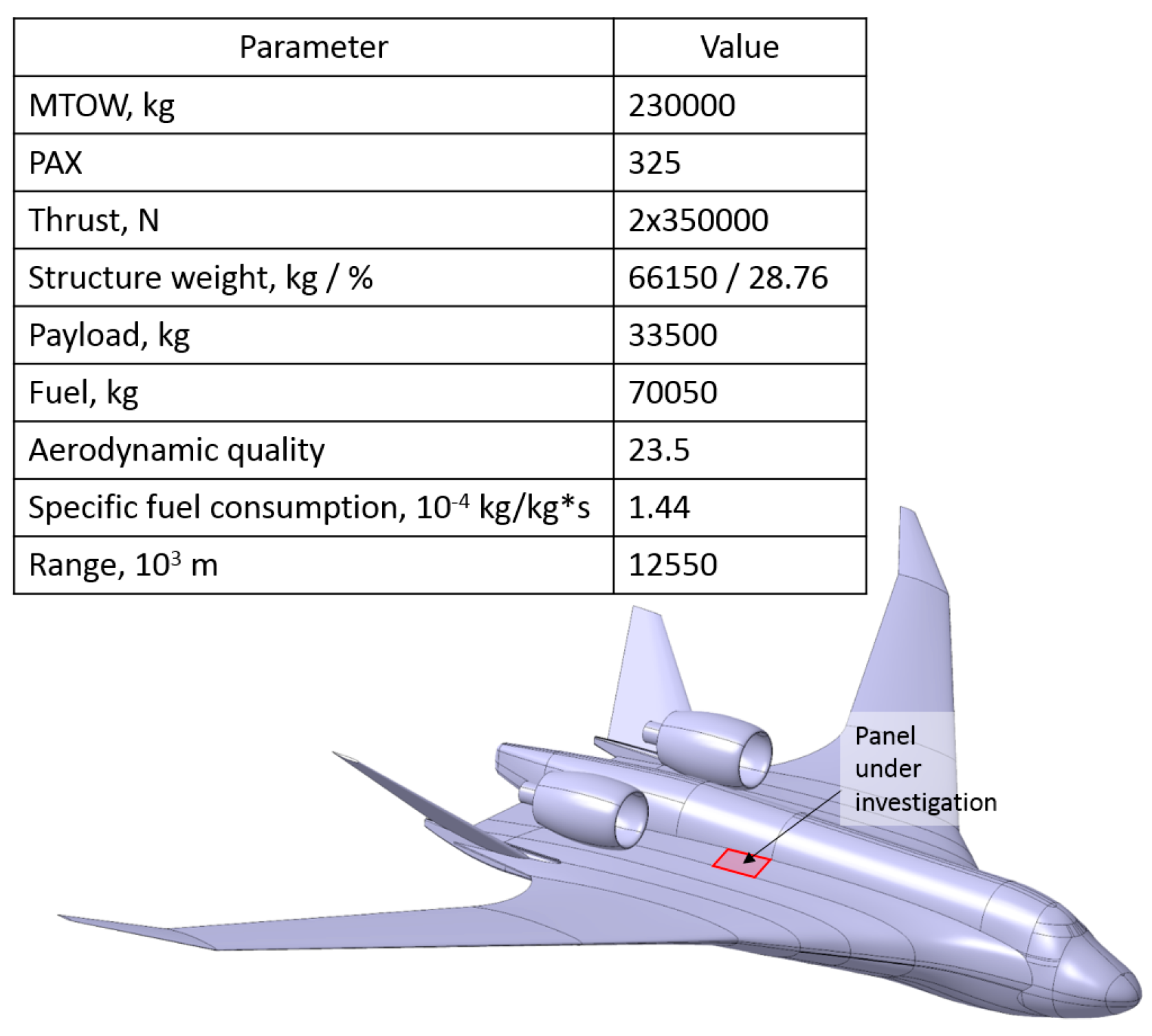
1. Introduction
2. Critical Strength Tasks of BWB Airframes
- (1)
- The large area of the outer surface, which leads to the appearance of large underloaded zones; and
- (2)
- The presence of large zones with a flat surface, subjected to considerable in-plane and out-of-plane loads.
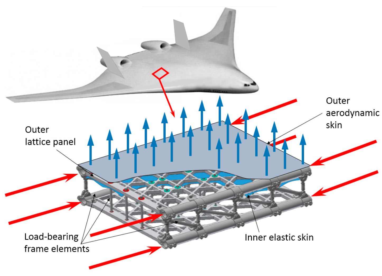
3. Double-Lattice Pressurized Flat Panels
3.1. Specific Features of the Double-Lattice Concept
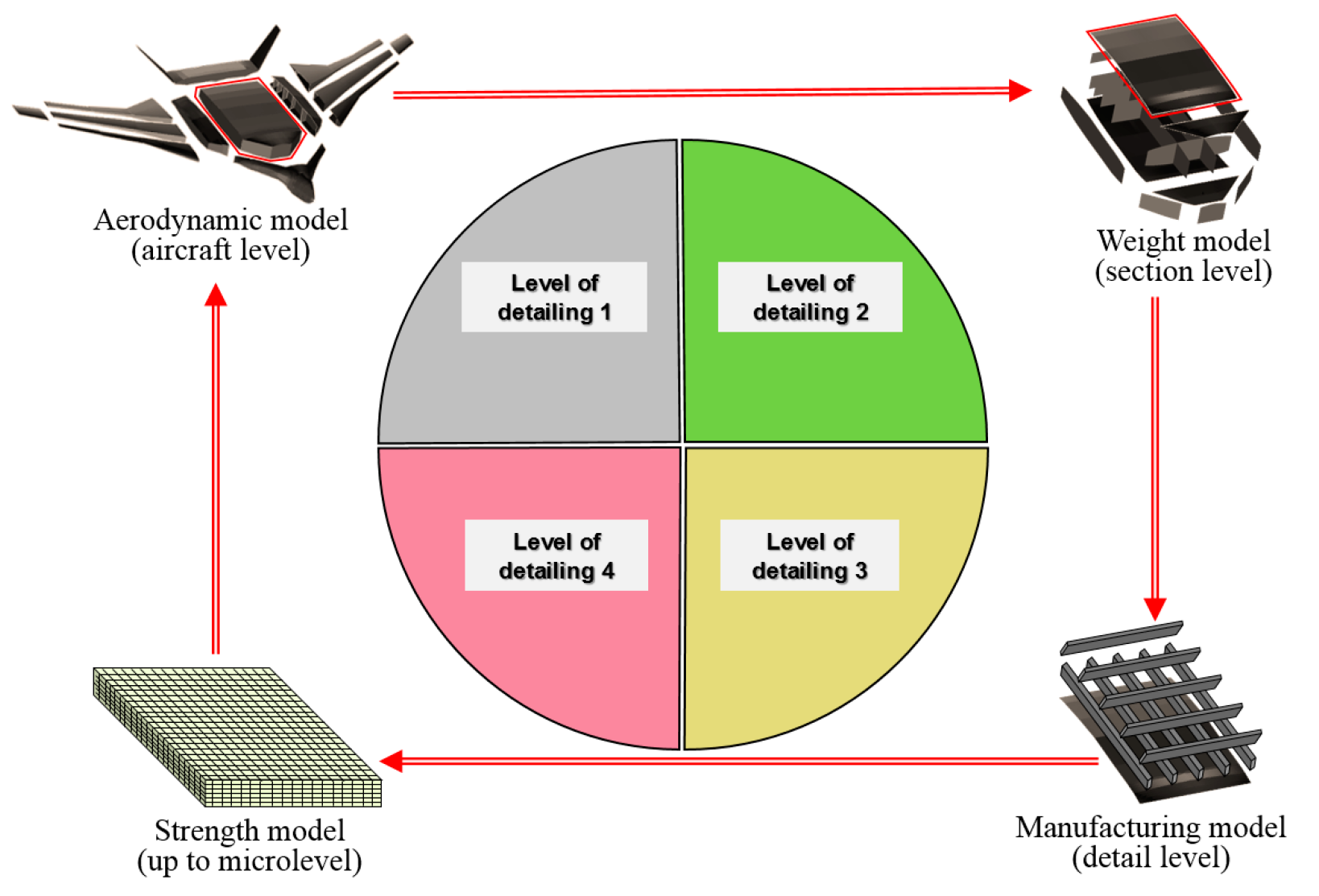
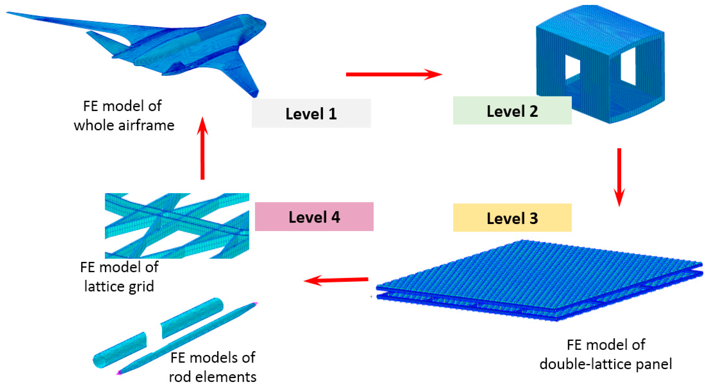
3.2. Four-Level Algorithm of Strength and Weight Analysis
- Nesting principle for the FE models of all levels;
- Automated generation of auxiliary analytical models for each of the four FE models;
- Full automation of the iterative procedure;
- Application of specialized databases of prototypes for the weight analysis; and
- Application of specialized databases of available manufacturing processes for the definition of the manufacturing constraints.
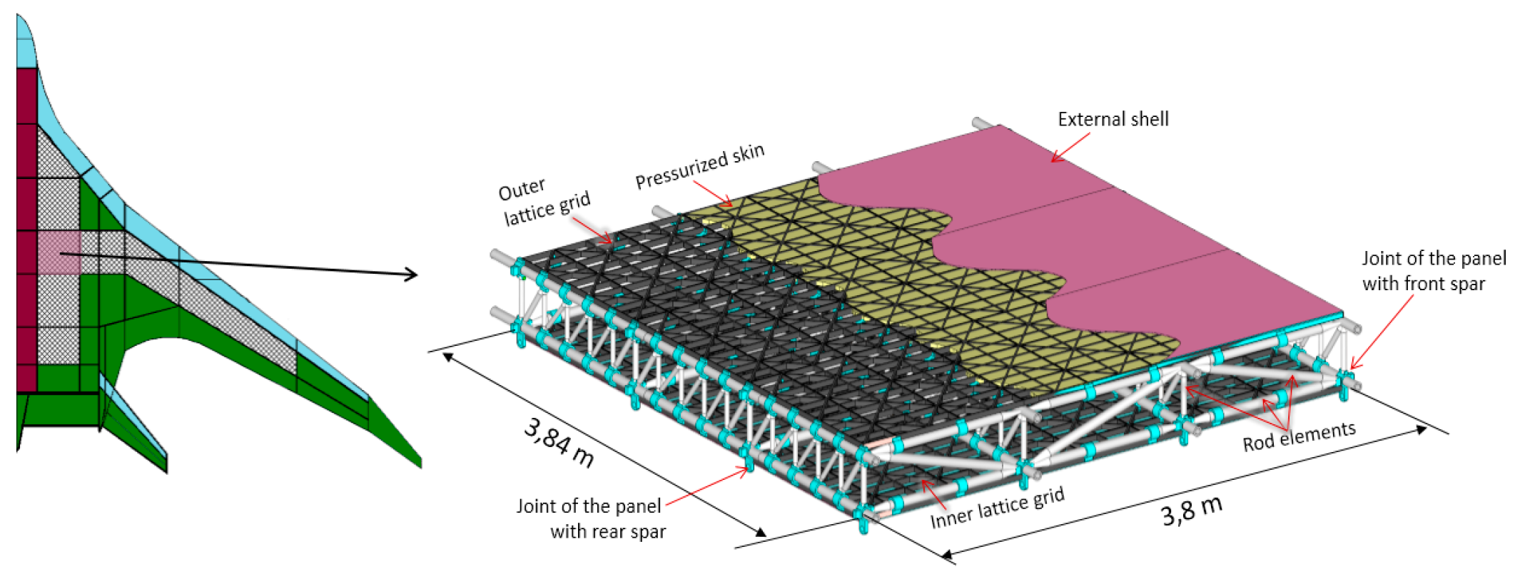
4. Main Elements of the Double-Lattice Panel and Their Manufacturing Realization
4.1. Primary Structural Elements of the Flat Panel
4.1.1. Hybrid Rods
- L—length of the rod element;
- L1, L2—length of the conical part;
- L3—length of the cylindrical part;
- R0—radius of the cylindrical part;
- R1—radius of the conical part near fitting;
- δ1—thickness of the protective layer;
- δ2—thickness of the composite layer.
4.1.2. Main Joints
4.1.3. Lattice Composite Grids
4.2. Low-Loaded Elements of the Flat Panel
4.2.1. Elastic Waveform Pressurized Skin
4.2.2. Outer Skin of the Panel
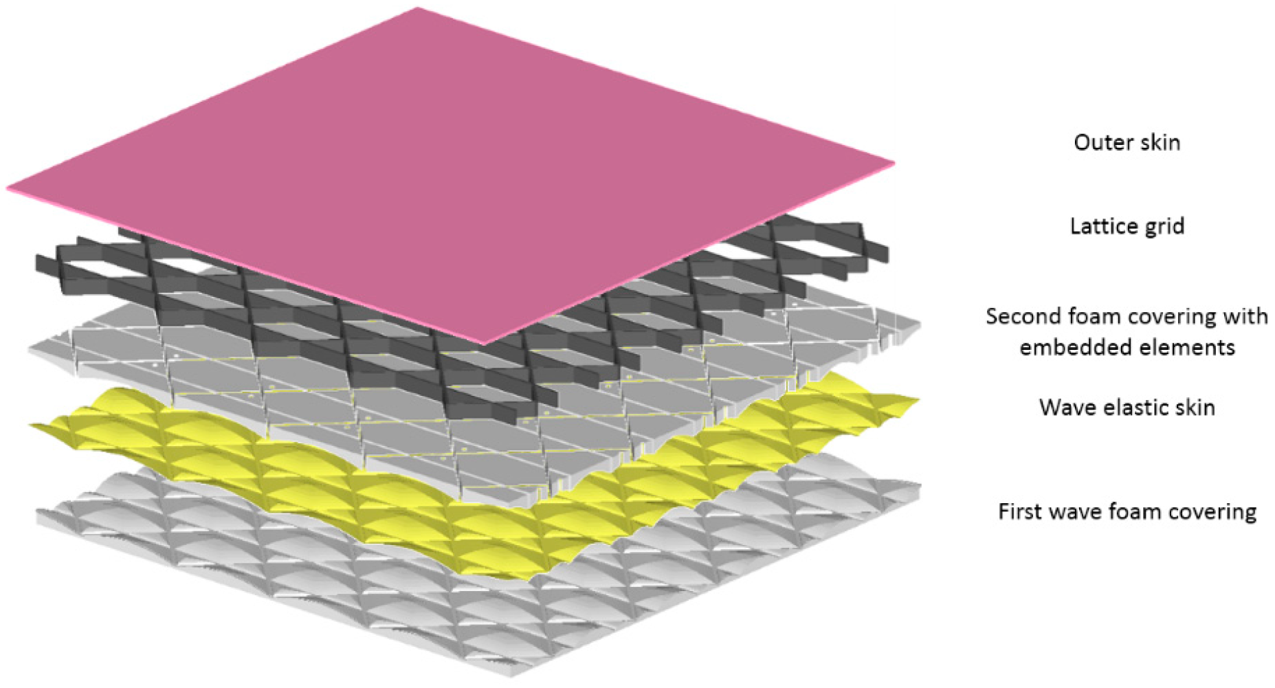
4.2.3. Thermal and Impact Protection Layers
- Form the local stiffness,
- Add thermal and impact protection,
- Attachment function (additionally, the outer skin can be connected to these layers by means of an adhesive joint),
- Foam coating for manufacturing.
4.3. Assortment of the Main Structural Elements
5. Multilevel Principle of Manufacturing and Repair of the Flat Double-Lattice Panel
- 1)
- Spatial frame skeleton including the rod elements and joints;
- 2)
- Outer subpanel including the outer lattice grid, wave elastic hermetic skin, wave foam covering, foam covering with embedded elements and outer elastic skin; and
- 3)
- Inner subpanel including the inner lattice grid, flat foam covering with embedded elements.
5.1. Main Stages of Manufacturing of the Panel
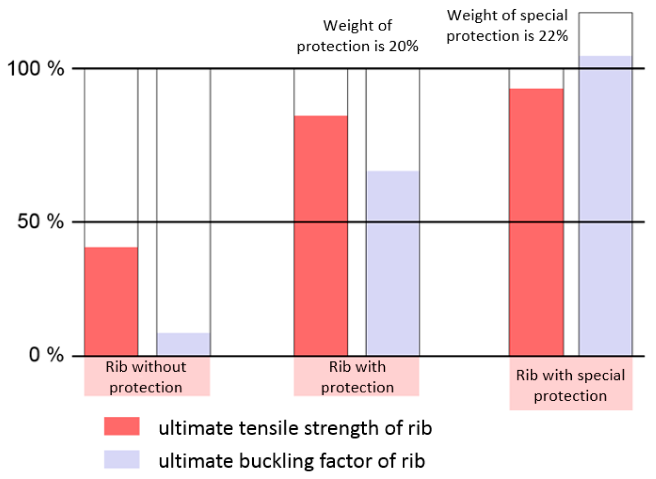
5.2. Multilevel Protection System for Primary Structural Elements of the Panel
- Layer of carbon fibers,
- Layer of elastic impact-absorbing materials,
- Layer of aramid fabric, distributing the impact energy on a larger area,
- Layer of chemical-resistant material.
- Minor damage repair: Repair of the skin and several ribs of the lattice grid.This is an in field type of repair and only requires standard equipment. The damaged skin is repaired using patches by means of bonding. The damaged zone of the lattice grid is filled with a polymer compound.
- Medium damage repair: Replacement of the skin and lattice for a significant part of the panel.Such types of repairs presume the replacement of the upper lattice sub-panel with a new one. The lattice sub-panel is connected with the frame by bolts and so can easily be removed.
- Hard damage repair: Replacement of the skin and one to two elements of the upper frame.
6. Estimation of Weight Efficiency of the Flat Pressurized Panel
7. Conclusions
Author Contributions
Funding
Conflicts of Interest
References
- FP6 NACRE Project. Available online: https://cordis.europa.eu/project/rcn/75773/reporting/en. (accessed on 13 February 2019).
- Okonkwo, P.; Smith, H. Review of evolving trends in blended wing body aircraft design. Prog. Aerosp. Sci. 2016, 82, 1–23. [Google Scholar] [CrossRef]
- Investigations of Technologies, Critical for Implementing an Airplane of Flying Wing Type with Superhigh Seating Capacity, ISTC Project #0548. Available online: http://www.istc.int/en/project/CAA832BC090C56E44325691F0011CAD4 (accessed on 13 February 2019).
- Denisov, V.E.; Bolsunovsky, A.L.; Buzoverya, N.P.; Gurevich, B.I.; Shkadov, L.M. Conceptual Design for Passenger Airplane of Very Large Passenger Capacity in the Flying Wing Layout. In Proceedings of the 20th Congress of the International Council of the Aeronautical Sciences, Sorrento, Italy, 8–13 September 1996; Volume II, pp. 1305–1311. [Google Scholar]
- Bolsunovsky, A.L.; Buzoverya, N.P.; Gurevich, B.I.; Denisov, V.E.; Shkadov, L.M.; Udzhukhu, A.Y. Investigations on possible characteristics of FW superhigh seating capacity airplane. In Proceedings of the 22nd Congress of the International Council of the Aeronautical Sciences, Harrogate, UK, 27 August–1 September 2000; pp. 116.1–116.9. [Google Scholar]
- Shanygin, A.; Dubovikov, E.; Fomin, V.; Mareskin, I.; Zichenkov, M. Designing pro-composite truss layout for load-bearing aircraft structures. Fatigue Fract. Eng. Mater. Struct. 2017, 40, 1612–1623. [Google Scholar] [CrossRef]
- Mareskin, I. Multidisciplinary optimization of pro-composite structural layouts of high loaded aircraft constructions. In Proceedings of the 30th Congress of the International Council of the Aeronautical Sciences, Daejeon, Korea, 25–30 September 2016. [Google Scholar]
- Dubovikov, E.; Fomin, V.; Kondakov, I.; Shanygin, A.; Vedernikov, D. Development of rational hybrid fuselage structure for prospective civil aircraft. Proc. Inst. Mech. Eng. Part G J. Aerosp. Eng. 2018. [Google Scholar] [CrossRef]
- Dubovikov, E.A. Novel approach and algorithm for searching rational nonconventional airframe concepts of new generation aircrafts. In Proceedings of the 28th Congress of the International Council of the Aeronautical Sciences (ICAS 2012), Brisbane, Australia, 23–28 September 2012. [Google Scholar]
- FP7 PoLaRBEAR Project. Available online: http://cordis.europa.eu/result/rcn/175990_en.html (accessed on 13 February 2019).
- Shanygin, A.; Fomin, V.; Zamula, G. Multilevel approach for strength and weight analyses of composite airframe structures. In Proceedings of the 27th Congress of the International Council of the Aeronautical Sciences, Nice, France, 19–24 September 2010. [Google Scholar]
- Kondakov, I.; Mareskin, I.; Shanygin, A.; Zichenkov, M. Features of design of hybrid airframes on the basis of unidirectional composite elements and metallic metamaterials. In Proceedings of the 15th Annual Russian-French Seminar TsAGI-ONERA, Sochi, Russia, 4–7 October 2016. [Google Scholar]
- Chernov, A.; Fomin, D.; Kondakov, I.; Mareskin, I.; Shanygin, A. Lightweight and reliable metal-composite joints based on harmonization of strength properties of joined parts. Proc. Inst. Mech. Eng. Part G J. Aerosp. Eng. 2018, 232, 2663–2672. [Google Scholar] [CrossRef]
- Vasiliev, V.V.; Razin, A.F. Anisogrid composite lattice structures for spacecraft and aircraft applications. Compos. Struct. 2006, 76, 182–189. [Google Scholar] [CrossRef]
- Dubovikov, E.; Fomin, V.; Hühne, C.; Kolesnikov, B.; Kondakov, I.; Niemann, S.; Shanygin, A.; Wagner, R. Anisogrid design for fuselage primary structures—Results of EU/RU projects ALaSCA and PoLaRBEAR. In Proceedings of the Royal Aeronautical Society’s 5th Aircraft Structural Design Conference, Manchester, UK, 4–6 October 2016. [Google Scholar]


| Figure | Element | Material | Manufacturing Method |
|---|---|---|---|
 | Horizontal axisymmetric rods | Carbon fiber composite prepreg | Automated fiber placement/winding on special foam preform |
 | Transversal (diagonal) and vertical axisymmetric rods | Metal for ends and composite prepreg for tube | Automated fiber placement/winding on special foam preform |
 | Lattice grids | Carbon fiber composite prepreg | Automated fiber placement |
 | Joints for axisymmetric rods and lattices | Metallic alloy | Additive manufacturing (3D printing) |
 | Wave elastic pressurized skins | Fabric prepreg | Fiber placement /braiding |
 | Outer aerodynamic skins | Fabric prepreg | Fiber placement /braiding |
 | Wave foam covering | Foam | Cutting |
 | Attachments (pins, bolts, screws) | Metallic alloy | Conventional metallic technologies |
| Element | Metallic | Black-metal Composite | ||||||
|---|---|---|---|---|---|---|---|---|
| Elastic modulus, GPa | Allowable stresses, MPa | Longitudinal elastic modulus, GPa | Allowable strains | |||||
| Tension | Compression | Shear | Tension | Compression | Shear | |||
| Skin | 72 | 350 | 250 | 200 | 57 | 0.4% | 0.3% | 0.5% |
| Stringers/ frames | 71 | 350 | 250 | 68.67 | 0.4% | 0.3% | 0.5% | |
| Webs of spars/ribs | 71 | 200 | 68.67 | 0.3% | 0.2% | 0.23% | ||
| Element | Material Name | Density kg/m3 | Longitudinal Elastic/ Shear Modulus GPa | Allowable Strains/Stresses | ||
|---|---|---|---|---|---|---|
| Tension | Compression | Shear | ||||
| Lattice grids | Hexply M21 | 1600 | 90/5.3 | 0.6% | 0.5% | |
| Composite parts of rod elements | Hexply M21 | 1600 | 88.6/8.7 | 0.8% | 0.7% | |
| Inner skin | Polystyrene | 1050 | 1.3/- | 80 MPa | ||
| Outer skin | Hexply M21 | 1600 | 57/21.5 | 0.4% | 0.3% | 0.2% |
| Joints | VТ6 titanium alloy | 4500 | 105/40.38 | 900 MPa | 900 MPa | 600 MPa |
| Lattice Grids (Outer and Inner) | Rod Elements | ||
|---|---|---|---|
| Parameter | Value, m | Parameter | Value, m |
| Height of ribs | 0.03 | Outer diameter of the inner horizontal axisymmetric rods | 0.1 |
| Width of diagonal ribs | 0.006 | Thickness of wall of the inner horizontal axisymmetric rods | 0.017 |
| Width of perimeter ribs | 0.009 | Outer diameter of the outer horizontal axisymmetric rods | 0.076 |
| Width of ribs orthogonal | 0.0025 | Thickness of wall of the outer horizontal axisymmetric rods | 0.011 |
| Outer diameter of the transversal (diagonal) and vertical axisymmetric rods | 0.02 | ||
| Thickness of wall of the transversal (diagonal) and vertical axisymmetric rods | 0.003 | ||
| Metallic Panel Elements | Weight | Composite Panel Elements | Weight | Double-lattice Panel Elements | Weight |
|---|---|---|---|---|---|
| Skin | 23.7 | Skin | 24.3 | Frame grid | 28.7 |
| Longitudinal stiffeners | 18.2 | Longitudinal stiffeners | 16.6 | Inner lattice grid with attachment | 9.2 |
| Transversal stiffeners | 12.1 | Transversal stiffeners | 11.9 | Outer lattice grid with attachment | 10.0 |
| Flanges of ribs | 4.2 | Flanges of ribs | 3.9 | Inner pressurized skin | 0.6 |
| Flanges of spars | 4.9 | Flanges of spars | 4.5 | Outer skin with thermal insulation layer | 2.2 |
| Attachment elements | 5.3 | Attachment elements | 4.0 | Protection of primary structural elements (including foam coverings) | 3.0 |
| Additional attachment elements | 2.4 | ||||
| Total | 68.4 (100%) | 65.2 (95%) | 56.1 (82%) |
© 2019 by the authors. Licensee MDPI, Basel, Switzerland. This article is an open access article distributed under the terms and conditions of the Creative Commons Attribution (CC BY) license (http://creativecommons.org/licenses/by/4.0/).
Share and Cite
Dubovikov, E.; Fomin, D.; Guseva, N.; Kondakov, I.; Kruychkov, E.; Mareskin, I.; Shanygin, A. Manufacturing Aspects of Creating Low-Curvature Panels for Prospective Civil Aircraft. Aerospace 2019, 6, 18. https://doi.org/10.3390/aerospace6020018
Dubovikov E, Fomin D, Guseva N, Kondakov I, Kruychkov E, Mareskin I, Shanygin A. Manufacturing Aspects of Creating Low-Curvature Panels for Prospective Civil Aircraft. Aerospace. 2019; 6(2):18. https://doi.org/10.3390/aerospace6020018
Chicago/Turabian StyleDubovikov, Evgeny, Danil Fomin, Natalia Guseva, Ivan Kondakov, Evgeny Kruychkov, Ivan Mareskin, and Alexander Shanygin. 2019. "Manufacturing Aspects of Creating Low-Curvature Panels for Prospective Civil Aircraft" Aerospace 6, no. 2: 18. https://doi.org/10.3390/aerospace6020018