1. Introduction
In recent years, the number of developments and launches of small satellites has been increasing, attracting the attention of investors seeking new businesses and of universities wanting to use them for research and educational purposes [
1,
2,
3]. In all cases, rapid development and low cost are required by stakeholders to support a satellite mission. In addition, a failure rate reduction has become crucial to the sustainability of the space programs [
4,
5].
One way to achieve both rapid development timelines and high reliability is by using a modular approach [
6,
7]. The Electrical Power System (EPS), responsible for power generation, storage and regulation, is particularly suitable for modular implementation [
8]. EPS is usually composed of solar array, battery, power control and regulation, and distribution and protection components [
9]. Each of these components can be modularized so that the design and development of the EPS become fast and reliable.
Due to the cost of solar cells and its importance, one of the most crucial steps in the design of the EPS is the design of the solar array. For this, the number of solar cells and their arrangement, in series or parallel connections, must be determined to satisfy the power requirements [
10]. Usually, various solar arrays of different sizes and arrangements are used in a single satellite [
11,
12,
13]. Another design approach is using one large solar array providing most of the power [
14]. These approaches have several disadvantages. Firstly, the design of the solar array becomes more complex, as the number of possible sizes and arrangements is high and each one needs a specific design. At the end, this increases the possibility of errors introduced at design time. Secondly, the EPS becomes less reliable; if one of the largest solar arrays fails, the satellite power is compromised. Thirdly, the efficiency of large solar arrays is not optimal because each cell is exposed to different radiation and temperature, but their set point is the same [
10]. Lastly, when different designs are used, additional time is required for qualification and testing.
In contrast, using solar array modules of the same, modest size and identical arrangement can increase the performance and reliability of the EPS, while reducing the development time. The performance is increased because the peak power of each solar array can be extracted by its own power regulator that implements maximum power point tracker; conversely, one power regulator for a solar array with different temperature and characteristics will extract less power [
10]. Reliability is also increased by connecting two or more components in parallel [
9]. Thus, EPS reliability is increased using solar array modules; if one solar array module fails, there are still other modules working as power source. Considering that identical modules will be used, the development time is reduced because the qualification process is done only one time. There is no need to qualify several designs. Then, the required number of identical modules will be manufactured and only the acceptance test is necessary, not the qualification test.
If a modular solar array is used, the design of the other components of the EPS can be realized independently, only including the number of required modules based on power requirements. Moreover, using the modular approach, power generation is decoupled from the rest of the EPS design [
15]. However, designing a solar array module is not a trivial task. Ideally, the module must be scalable and easy to integrate; it must have a low cost, high efficiency and high reliability. However, these ideal features are usually in conflict, thus it is common to perform a trade-off.
Solar modules have been previously proposed in literature [
8,
14,
16,
17]. The proposed designs for the power generation module vary in complexity. The modules proposed in [
16,
17] only integrate the solar array while power regulation and housekeeping measurements are proposed as a different module. Integrating these three functions (solar array, power regulation and housekeeping measurements) in a single module increases the level of abstraction of the module, making the EPS design easier. One such module is proposed in [
8]. However, their power regulation does not manipulate the solar array operating point to achieve maximum power. The design in [
14] integrates the solar array and housekeeping but no power regulation, however, this design includes a magnetic actuator for attitude control.
The design of a modular solar power generation component including solar array, power regulation and measurements, depends on the satellite size and its voltage and current requirements. Therefore, a single module design will hardly fit a different satellite than that for which it was designed, and new missions need to design their own modules. As previously mentioned, this is not an easy task as it involves a large combination space and many relationships among the different decisions to be made. For this reason, the objective of this study was to provide design considerations and a verification process for electric power system modules by integrating the solar cells, the power regulator and telemetry acquisition units to reduce the development time of small spacecraft while adding redundancy in the power source. The novelty and significance of this study is the proposal of a design and qualification approach for Solar Module Integrated Converters (SMICs), which can be used as a guide for new missions to design and evaluate a solar module for power generation easily.
The contributions of this paper are as follows:
We propose a Solar Module Integrated Converter to integrate the solar array, the solar array regulator with peak power tracker and the measurement circuit in a single module (
Section 2.1).
Since we understand that a single design is hard to realize, we propose a design and qualification method for SMIC that can be used to adapt the sizing of each module to a particular mission (
Section 2.2 and
Section 2.3).
We applied the proposed method to the design and qualification of the SMIC for Ten-Koh satellite, showing how the proposed SMIC and methods were used in specific mission design (
Section 3).
We present results of Ten-Koh Solar power generation flight data recorded during operation in-orbit, which verifies and validates the proposed SMIC and design approach (
Section 4).
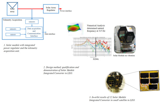
The SMIC module for Ten-Koh satellite integrates power generation with triple junction solar cells, solar array regulation based on peak power tracking, and measurements for housekeeping data collection that include current, voltage and photo-diode for sun incidence angle estimation. The designed module was qualified for space use following the proposed verification method and integrated into the quasi-spherical satellite Ten-Koh launched on 29 October 2018. The satellite and its SMIC are shown in
Figure 1. Twelve identical modules were integrated to Ten-Koh satellite, which has been operating continuously for five months.
2. A Modular Design Approach for Solar Array
In this section, we describe the proposed architecture for a solar power generation module (
Section 2.1), named Solar Module Integrated Converter (SMIC). As stated in
Section 1, a “silver bullet” module design that fits satellites with different sizes, shapes and power requirements does not exist. Therefore, we detail some design considerations to guide the design of SMIC for specific mission requirements. Finally, we delineate a validation and verification plan for such SMIC.
2.1. SMIC Architecture
The EPS of a satellite is responsible for generation, storage and distribution of power. In this paper, we propose a modular architecture and design approach for the power generation function. The proposed SMIC defines a core array that can be used to create a multi-array of solar cells (
Figure 2). Each module also contains the solar array regulator (SAR), thus it becomes a plug-and-play energy source ready to be integrated with the rest of the EPS. We also propose to include the sensors and interfaces for housekeeping data generation and communication into the SMIC (
Figure 3). This makes the entire power generation part of the EPS arbitrarily scalable while minimizing the impact on the rest of the satellite system.
Thanks to using a modular approach, the development time is reduced and power generation efficiency can be increased as compared to a typical configuration where multiple solar array designs are used. In summary, the advantages of the modular approach are the following:
By designing a module, the design and implementation become easier and the designed solar array can be reused in each face of the satellite.
All verification and validation tests can be done on a single module instead of all installed modules.
The power output of each solar array will be optimized even if they have different radiation and temperature conditions.
The following subsections describe each component of the SMIC.
2.1.1. Solar Power Generation Unit
This component is the energy source of the spacecraft, which for small satellites tends to be derived from solar arrays. A solar array is formed by connecting several solar cells in series, parallel or series-parallel. Series connection is used to increase the voltage of the SMIC. Parallel connection is used to increase current and avoid losing the string when one solar cell of the array is damaged [
18]. A series-parallel connection combines both objectives.
As shown in
Figure 2, two or more SMICs can be connected together to meet the total power requirements of the satellite mission. As in the case of solar cells, SMICs are connected in series, parallel or series-parallel following the same logic. In the design approach section (
Section 2.2), we describe how to make the decisions of the number of cells and type of connection to use.
2.1.2. Solar Array Regulator
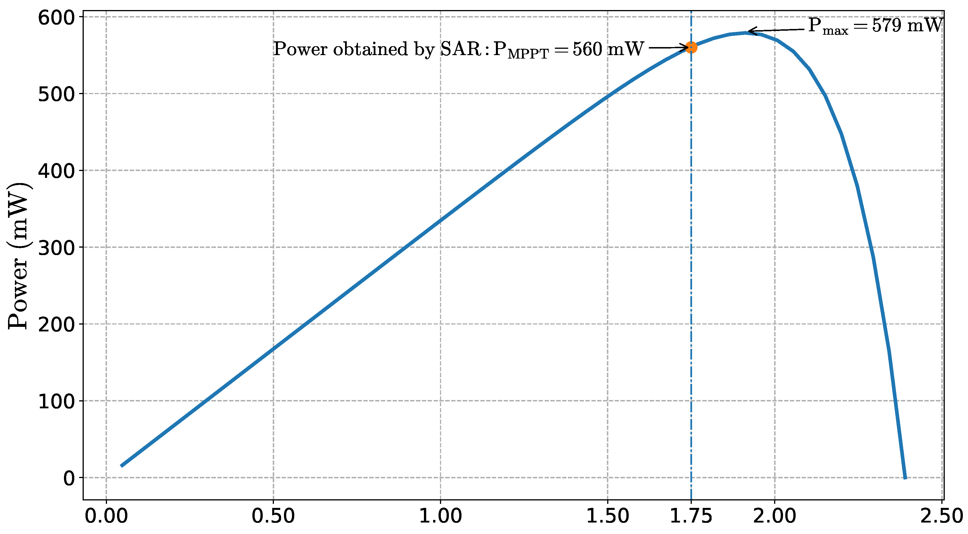
The Solar Array Regulator (SAR) has two main functions. The first one is to match the solar array and the load to obtain the maximum power available from the array. Even when the solar cells receive the maximum irradiance, the power generated from them can be minimum if there is a load mismatch. The second function of the SAR is to prevent the batteries from overcharging by controlling the power generated by the solar array according to their charge state.
There are mainly two approaches for solar array regulators to obtain the maximum power given a condition of temperature and sun incidence angle: Direct Energy Transfer and Maximum Power Point Tracker (MPPT) [
9,
19]. Both can achieve a load matching to obtain maximum power from the solar array. However, DET can obtain the maximum power just for one specific condition while MPPT can continuously track the maximum power point.
Both techniques of solar regulators can be used in a modular approach [
8]. In the proposed SMIC architecture, we chose to implement MPPT because it offers several advantages compared to DET. Firstly, MPPT allows the use of solar arrays with different voltage levels, thus it can be used in different EPS. Secondly, the power output of each solar array will be optimized even for different radiation and temperature [
20]. Thus, MPPT is optimal when installed in satellites using body mounted solar cells, in which each side experiences different conditions. This is equivalent to having a distributed photovoltaic system [
21,
22].
2.1.3. Telemetry Acquisition Unit
This component is responsible for measuring the operating conditions of the whole SMIC. These measurements must be provided to the satellite data handling subsystem through a data interface such as I2C, SPI, etc. [
23]. The most important measurements to monitor the health condition of the solar panels are their currents, voltages and temperatures. Sensors for measuring these variables must be installed in the SMIC.
Besides measuring the health of the energy source and the satellite itself, other sensors can also be installed in the SMIC to obtain additional data about the operating conditions. For example, the sun incidence angle on each solar panel can be measured by installing sun sensors in the SMIC. The measurements provided by this component can be used for other purposes in the satellite mission, e.g., including satellite attitude estimation [
24].
2.2. SMIC Design
We now move on to the design approach for the SMIC. During the SMIC design, decisions about which exact solar cells will be used, the number of solar cells in each array, how the cells are connected, the topology of the MPPT and which sensors will be installed must be made. These decisions are tightly coupled, thus changing one variable will affect the decision for all others. Moreover, the number of possible values for every decision can be high. Thus, designing the SMIC can become a difficult task. The purpose of this section is to provide a guideline for designers to facilitate the process, focusing on the design of the solar array regulator and the power generation component. Selection of telemetry sensors should be done according to the desired measurements.
2.2.1. Design of Solar Array Regulator
We propose to begin the design by defining the Solar Array Regulator (SAR). The SAR choice will restrict the maximum voltage that can be provided by the Power Generation Component [
10]. This restriction is mainly given by the choice of the topology of the MPPT. Thus, selecting one topology with high efficiency is a key element in the design process [
25]. The main topologies are buck converter, boost converter or buck-boost converter. Other topologies such as SEPIC or Cuck are popular for implementing MPPT in direct current power systems, but we only discuss the implications in the design of the main topologies.
When choosing the buck-converter topology, the voltage must be higher than that of the batteries. When choosing the boost converter, the voltage must be lower than that of the batteries. We assume the battery has been selected previously, thus this voltage is known and considered a constraint for the design.
When choosing the buck-boost converter, there is no restriction in terms of voltage related to the battery. However, it still has the restriction of the maximum rating, meaning the maximum operating voltage and current. This restriction also applies to the buck converter and to the boost converter.
2.2.2. Design of Solar Power Generation Unit
The next step in the design process of the SMIC is designing the solar array. This is the most important step because it determines the power available from the module. There are three decisions to be made: (1) the solar cells to be used; (2) the number of cells in each module; and (3) connection between the cells. This is an iterative process as one decision can be updated based on the results of later decisions.
The type of solar cells is decided based on mission constraints, most notably the budget and availability of the cells on the market. Nowadays, commercially-available triple-junction solar cells can achieve efficiency of up to 30 % and they are commonly manufactured in sizes around 30 cm
2 and 26 cm
2 [
26,
27,
28]. An initial type of solar cells can be chosen to continue with the design. It can be updated later if the power balance is not met with the chosen cells, or if lower-cost cells can provide sufficient power.
After choosing the type of solar cells, the number of solar cells to be installed must be decided. To choose the number of cells in each module, we must first know the total number of cells that will be installed in the satellite. The typical approach for CubeSats and small satellites without deployable solar arrays is to cover the maximum area of external surface with solar cells. However, this approach can be costly and lead to an over-sized array. Conversely, if the number of installed solar cells is not enough to operate the satellite, the mission is not feasible. To avoid a high cost, the number of cells on each side can be determined by doing an energy balance.
The energy balance is obtained by matching the satellite power requirements with the power generation. Power requirements of the mission determine the total number of solar cells mounted on the satellite because the amount of power generated is directly related to the number of solar cells. The total solar power generated is approximately the sum of the power generated by each module
where
m is the number of SMICs and
is the power generated by the module number
j, which is a function of the area covered by the cells in the SMIC (
) and the incidence angle of the sun with the module (
).
Specifically, assuming that the maximum power can be obtained, the power generation of a solar module,
, depends on the illuminated area of the module,
, and is given by
where
is the solar constant given by the orbit,
is the efficiency of the solar cells [
29]. Considering the illuminated area is a function of the incidence angle, the power generated by each module can be different, especially in satellites with body mounted solar cells [
30]. In this case, sides with different solar incidence angle will generate different power.
An initial number of cells in each SMIC can be determined by the available area to install each module. In the case of body mounted solar cells, as is the case for most small satellites, this area is given by the satellite structure. This area is divided by the solar cell area to determine the number of cells to be considered. After this, the generated power is calculated and the number of cells can be adjusted accordingly. If the power generated is too high, the number of cells in each module, or the number of modules, can be reduced. If the power generated is too low, then the type of solar cells should be changed for one with more efficiency.
Since the incidence angle depends on time, the generated power used for evaluating the design can be obtained based on the average power by simulation. Another approach to calculate the generated power can consider only the scenario of minimum power generation when the illuminated area is minimum; this case is simpler and more conservative. The generated power is used for adjusting the number of cells based on energy balance.
Once the number of solar cells is defined, the electric configuration of the solar array is determined by the input requirements of the solar array regulators. In this way, the maximum voltage or maximum current of the SAR are respected to ensure its safe operation. The voltage range of the SAR determines the number of cells that can be connected in series. This can be set as an initial constraint. The array is completed by connecting the cells in parallel without exceeding the current rate of the SAR.
2.3. SMIC Verification Approach
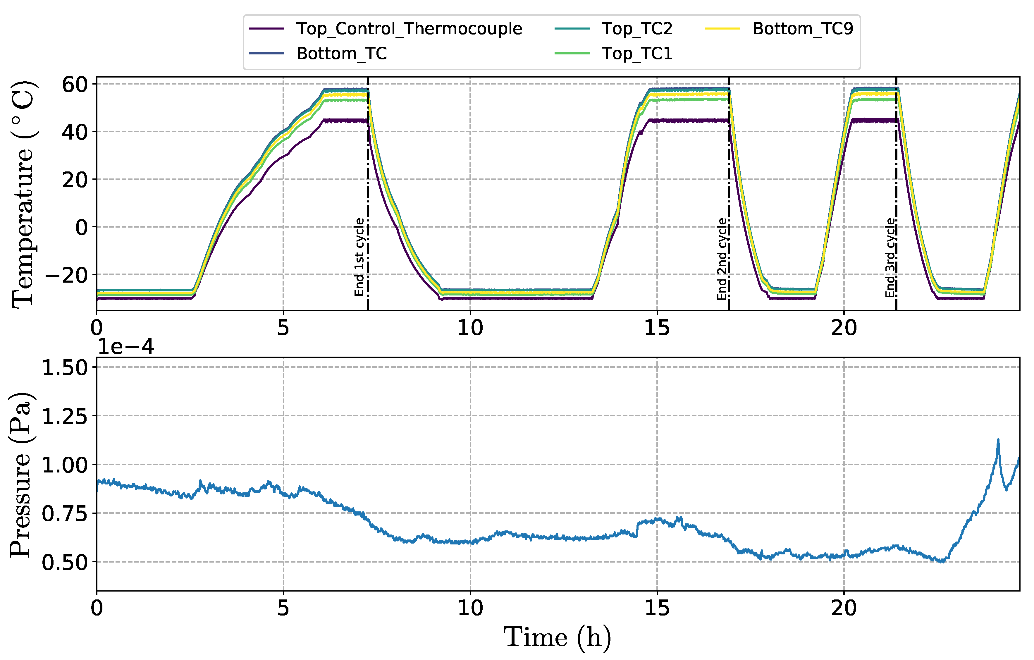
The goal of the verification process is to confirm that the SMIC is able to withstand the vibration and shock experienced during launch, and the thermal cycling expected in orbit. This is to say that the mechanical and thermal-vacuum conditions should not affect the functions of the SMIC, or reduce its performance. As presented in
Section 2.1, the SMIC can be split into three functional units:
The solar array is likely orders of magnitude more expensive than SAR and TMA units due to the high cost of space-grade solar cells relative to Commercial of-the-shelf (COTS) integrated circuits, which form the backbone of the SAR and TMA units. It is, therefore, desirable to reduce the number of Qualification Models (QMs) of the solar array units and to reduce the amount of testing that they are subjected to, in order to reduce the overall project cost. However, the qualification process should be as complete, and representative of the launch and flight conditions as possible to ensure that the flight SMIC will correctly function in orbit.
One way to address this reliability–cost–risk trade-off is to use the Proto-Flight Model (PFM) approach in the qualification of the SMICs. However, if this approach is followed, eventual design flaws cannot be rectified without re-working all PFMs close to the launch date, which will have a cost and schedule impact on the project. In the case of piggyback satellites, it could even mean missing the launch opportunity altogether. To mitigate the risk of missing the launch, the qualification approach depicted in
Figure 4 is proposed for SMICs.
First, the qualification models of the SMIC TMA and SAR units need to be tested with the rest of the satellite during the system-level qualification campaign. Functionality of the units should be verified before and after mechanical testing (green blocks in
Figure 4) to ensure that they can survive the launch without loss of performance. At this stage, dummy masses of the solar arrays can be used and the vibration spectra on them should be measured.
The measured vibration spectra must then be compared to the solar array natural frequency (
) computed using a finite element model (FEM), in order to assess whether
of the solar array is above the peak of the vibration spectra, i.e., whether the solar array is likely to withstand the vibration environment. Once this is confirmed, one qualification model of the solar array can be manufactured, and a complete SMIC will be subjected to qualification mechanical and thermal vacuum testing (right-hand side of
Figure 4). To confirm no damage has been sustained by the solar array throughout the qualification testing, current–voltage curves of the solar cells should be measured before and after each test (blue blocks in
Figure 4). The curves can be obtained by measuring the current and voltage while the load is changed when the solar array is illuminated at constant irradiance [
31]. At the end, the SMIC should be functionally tested in an integrated subsystem test to ensure that it correctly interfaces with other components of the EPS.
3. Applying Solar Module Design to Ten-Koh Satellite
In this section, we use Ten-Koh satellite as a case study to apply the proposed guidelines to the design of the SMIC.
3.1. Power Needs and Constraints for Case Study: Ten-Koh Satellite
The main function of the solar array is to provide the power required by satellite bus and payloads to achieve the satellite mission. The solar array is designed under two constraints: (1) the orbit that determines the amount of solar irradiance and the time of sunlight and eclipse; and (2) the geometry of the satellite that determines the operating conditions of the solar array, for example, its incidence angle.
3.1.1. Satellite Orbit
As mentioned above, the orbit determines the sun intensity or solar irradiance received by the satellite. Ten-Koh satellite was launched as a piggyback payload of GOSAT-2 into a sun-synchronous, sub-recurrent orbit. The initial orbit altitude,
h, was 613 km and the orbit period,
, was 5817 s (about 1.6 h). This can be calculated as
where
is the Earth gravity parameter (398,600.44 km
) and
is the mean Earth radius (6378.14 km).
This orbit determines that the average irradiance received by Ten-Koh is 1367 W/m
2, the solar constant,
. This is the solar energy potential that reaches each SMIC on the spacecraft. However, the generated power per SMIC (
) is determined by its angle in the spacecraft (that defines the incidence angle,
) and the number of solar cells (that defines the area covered by the cells,
) as given by Equation (
2). Then, the total energy produced during each orbit period is calculated using the total solar power generated (
, from Equation (
1)) and the sunlight time. From the satellite orbit, the sunlight time and eclipse time are 3715 sand 2092 s, respectively. Thus, the satellite is receiving sunlight during 63 % of the orbit.
Section 3.3 shows the calculation for the spacecraft orientation with the worst condition to determine the number of solar cells in the SMIC considering the minimum energy generation.
3.1.2. Power Requirements
The power required by satellite subsystems to operate must be provided by the solar array. Ten-Koh platform has the following subsystems: on-board computer (OBC), two redundant communications subsystems (COM-1 and COM-2), Attitude Determination Subsystem (ADS), and Electrical Power Subsystem (EPS). Secondary Payloads (PL-2) and Primary Payload Components are: Experiment Control Unit (ECU), Double Langmuir Probe (DLP) and Charge Particle Detector (CPD).
Table 1 shows the power required by each subsystem during operation.
As many satellites, Ten-Koh has different modes of operation. Each mode determines which subsystems are powered on, while the others remain turned off. Therefore, energy balance for different operating modes can be analyzed by combining the power and the duration of the corresponding operating mode.
In
Table 1, the CPD mission is the subsystem with the highest power consumption. This mission is operated for at most 32 min in one day. We used a scenario of one-day operation with CPD mission to design the Ten-Koh SMIC. The total power required to power the spacecraft during nominal mode is
W and
W during CPD mission. Then, the minimum energy required to execute the mission is
Wh.
3.2. Solar Array Regulator
The solar array regulator (SAR) used in the module is based on Maximum Power Point Tracking (MPPT) to optimize the power generation of the solar cells.
Table 2 shows the requirements for normal operation of the selected MPPT (SPV1040).
As mentioned in the design approach, the topology of the dc-dc converter is a constraint for design the solar and battery arrays. In Ten-Koh, the MPPT selected is based on boost converter, thus the voltage of the solar array must be lower than the battery array. Ten-Koh battery array voltage can vary between V and W.
3.3. Solar Array Configuration
We designed the Ten-Koh SMIC as a module for a solar array that can be installed on both hexagonal and square faces of the satellite. Therefore, the maximum number of solar cells in each SMIC is determined by the smallest side of Ten-Koh. This is the square face with length of 15.2 cm, which has an area of 231 cm2.
With this area in mind, we selected the solar cells to be installed. The electric characteristics of commercial solar cells are listed in
Table 3. The cells with
cm
2 were selected to cover more area in the module and have more power generation.
By simple area analysis, we can install up to eight cells in each module. However, considering the space of the terminals of the solar cells, and the space for temperature and sun sensors, we could only install six cells in the module. If solar cells of cm2 were selected, then three solar cells could be installed in the module.
Using the worst case scenario, we considered a case when solar radiation is perpendicular to the top side of Ten-Koh, which has no SMIC installed (
Figure 5). This is the same case as when solar radiation is perpendicular to Ten-Koh launcher adapter ring. In this scenario, only six modules receive solar irradiance at an angle of 70 degrees for the hexagonal and 55 degrees for the square faces. This analysis gave us a total power of
W and, considering the sunlit time of the orbit, the minimum energy generation of
Wh. This exceeded the needs of Ten-Koh (
Wh). Therefore, we decided to use only five cells, which still satisfied the energy balance. In the worst case, the generated power with five cells per module was
W. Thus, the minimum energy generation is
Wh, which was enough to meet Ten-Koh energy requirement.
Table 4 shows the comparison of the number of cells for the three cases previously described. Using the modular and power balance design approach, we reduced costs and development time in Ten-Koh.
Once the number of cells was decided, it was necessary to define the electrical configuration of the array. Because the maximum voltage of SAR is V, no series connection can be made, as two serial cells would give a maximum voltage of V, which is higher than the battery voltage ( V). This resulted in a parallel connection of all cells.
Although all five cells could be connected in a parallel configuration, no commercially available solar array regulator could handle the total power of five cells (see
Table 2). For this reason, we connected two arrays in each SMIC: one array of two cells in parallel and the other with three cells in parallel. In these two sub-arrays, the solar cells are connected in parallel by using near-ideal diodes (LTC4412) to prevent a single cell with a short-circuit from disabling an entire array. The only difference between both arrays is the provided current.
3.4. Solar Module Measurements
As for measurements, we decided to include voltage, current, temperature and sun incidence angle. One temperature sensor and one four-quadrant photodiode were installed on the external side of the SMIC. The internal side included two current sensors and one voltage sensor for power monitoring. All sensors provided analogue outputs.
A high speed, low power analog to digital converter (ADC) was used for data acquisition of the measurements of the solar module (AD7927). The converter includes one serial interface (SPI) to transmit the conversion results of the eight analog inputs to a microcontroller.
As explained above, there are two sub-arrays in every module, one with two cells and the other with three cells. The output current of every array is measured by using a shunt resistor with a current-sense amplifier. Only the voltage of the array with three cells is measured to have more channels available for attitude determination sensors and without increasing the required number of ADCs.
A two-terminal linear temperature transducer (AD590) that does not require cold junction compensation or special signal conditioning circuit was used to measure the external temperature of the solar panel. A current-to-voltage conversion resistor was used to couple the output to the input of the ADC.
A COTS quadrant Si PIN photodiode (S4349) was mounted on every solar module. The photodiode was aligned with the plane of the solar module; in this way, its output is related to the incidence angle of the solar irradiance. The four outputs are converted to voltage and connected to the ADC.
5. On-Orbit Results of Twelve SMIC
Figure 14 presents the time series of Ten-Koh battery voltage and the battery charge currents—two identical batteries have been connected in parallel for redundancy purposes. Negative current has been defined as charging the battery. Since both batteries have been connected in parallel, the combined current for both is the sum of the two currents. Despite the parallel connection, the two currents are consistently different, which is analyzed in more detail below in this section.
The first observation to be made is that the battery retained its voltage for a duration of nearly five months of spacecraft operations, meaning that the SMICs remained functional and were able to charge the battery and supply power to the spacecraft loads. The data in
Figure 14 were obtained from the spacecraft beacons transmitted while it was in view of a ground station. Thus, the data become increasingly more scarce after launch, as the radio-amateur community stopped frequently tracking the satellite over time. This fact notwithstanding, the spacecraft remained operational and the battery was charged, meaning that the SMICs were able to supply power to the satellite.
As shown in
Figure 15, the SMICs were able to provide up to 0.89 A of battery charge current (mean charge current was 0.54 A, and the median was 0.52 A). Note that
Figure 15 is a cumulative histogram showing the fraction of all measurements that saw a current greater than the corresponding X-axis value. For example,
of all measurements had a current greater than
A.
Figure 16 shows the total power generated by the SMICs and the battery voltage over the duration of one orbit. The measurements were taken and stored in satellite on-board memory at an interval of 90 seconds, and later downlinked to ground. In addition to the battery charge current, the spacecraft consumption in sunlight was expected to be
W. The SMICs were able to provide instantaneous power between 4.35 and 6.68 W during this orbit (up to
A in sunlight and
A in eclipse). In addition, it can be noted that the battery voltage was varying according to whether power was being provided to it by the SMIC or not. This means that the SMICs were charging the battery in sunlight, i.e., between Minutes 14 and 75 of the orbit. At that time, the SMIC power output was varying depending on the attitude of the spacecraft.
The difference between the currents of both batteries over the same orbit as in
Figure 16 is shown in
Figure 17. The telemetry of the two batteries is consistently different even though they are connected in parallel and should theoretically discharge and be charged with the same currents. The same behavior was observed when analyzing data from
Figure 14. The difference in the current of the two batteries is larger during the sunlit part of the orbit (between Minutes 14 and 75 in
Figure 17) than in eclipse. However, the difference between the two currents was at most 0.132 A during charging and 0.059 A during the eclipse. This is an order of magnitude less than the measured currents and, therefore, does not affect the results of the above discussion. The difference between both battery currents (
Figure 17) could be caused by an imbalance of the batteries or inaccuracy of the telemetries. The latter is most probable because the difference is higher during the sunlit that during the eclipse, this means the measuring circuit of battery current 1 (
) has a higher gain than the measuring circuit of battery current 1 (
) during the charging process. Based on the orbits results of one orbit and telemetry received by radio amateurs,
Figure 14 and
Figure 17 show SMICs providing the power during the sunlit keeping the batteries charged for the operation during the eclipse. This is also a confirmation that SMICs withstand the launch environment and about five months in LEO, more than 1500 orbits.
6. Conclusions
We present a modular approach for the power generation component of small satellites, called Solar Module Integrated Converter. The general architecture of the SMIC, design considerations and evaluation approach are proposed and detailed. Moreover, we applied the proposed SMIC architecture and method to the design of solar array for Ten-Koh satellite. The modular approach allows the inclusion of multiple functional requirements in one module such as power generation, solar array regulator and measurements required for housekeeping.
Using SMIC for solar power generation reduces the complexity in both design and testing for small satellites. This effectively reduces the development time and costs of the mission without sacrificing quality and reliability because only one module is designed and qualified to confirm that it meets the functional requirements, as well as withstands the launch and in-orbit environments and then the required number of SMIC are manufactured. In the case of Ten-Koh satellite, after one module was successfully qualified, 12 SMIC were manufactured and integrated into the spacecraft.
SMIC allows incremental development for space programs. An updated or alternative version can be designed without changing the rest of the EPS. For example, the exemplar SMIC module includes MPPT as solar array regulator for maximum power generation. The integration of the MPPT allows modules that are more flexible and scalable because MPPT uses a power converter that matches the solar array to the battery to extract more power. In the case of using DET for solar modules, the flexibility is reduced because it can efficiently work only when the battery voltage matches the solar cells. However, in some cases, we recommend changing MPPT for DET as SAR. For example, when the satellite has a fixed orientation with respect to the sun vector and there is little change of the incidence angle. Selecting DET in SMIC does not change the proposed design approach because DET also imposes restrictions on the voltage that is used as input for the solar array design. The trade-off between DET or MPPT can be challenging in certain cases and, for this reason, we limited our analysis to MPPT without loss of generality. In the same way, new SMIC can be designed changing the MPPT technique or the number of cells in the solar array to adapt the module to new missions.
Functionalities integrated into SMIC are strongly related. Solar arrays always require a solar power regulator, thus it is advantageous to have these functions in the same module. In the same way, the measurements or solar arrays are required for the housekeeping of most of the spacecraft. Thus, SMICs also contributes to the reliability of the spacecraft because they facilitate the implementation of redundancy of solar arrays, solar arrays regulator and telemetry acquisition units. In the case of Ten-Koh, 12 SMICs were connected in parallel; if one of the SMICs is damaged, then there are still 11 more providing power and their corresponding measurements.
In brief, SMIC reduces complexity, and, hence, cost and development time. SMICs are also good because the design of the EPS is decoupled from the power source giving the possibility to update the modules without affecting the rest of the EPS design. SMICs also facilitate the implementation of redundancy that increases the reliability of the spacecraft. The SMIC design for Ten-Koh followed the proposed design and qualification approach. The satellite was developed over 1.5 years and launched in October 2018, and the success of the SMIC has been confirmed via telemetry data. According to the in-orbit measurements, the total power provided by the solar array to charge the battery during sunlight was calculated to be 4–6 W. Based on this success, we are confident that the modular approach worked in Ten-Koh and the proposed method can help other missions to reduce the development time while ensuring mission success.

 ,
, 


