Sound Transmission Analysis of Viscoelastic Composite Multilayered Shells Structures


Faculty of Engineering and Architecture, Kore University of Enna, 94100 Enna, Italy
*
Author to whom correspondence should be addressed.
Aerospace 2019, 6(6), 69; https://doi.org/10.3390/aerospace6060069
Submission received: 20 May 2019
/
Revised: 1 June 2019
/
Accepted: 3 June 2019
/
Published: 6 June 2019
Abstract
:In the development of aircraft comfort, one of the main issues is the sound transmission analysis to estimate the insulation capability of aeronautical panels. In this work, a higher-order shell finite element is proposed for the passive noise insulation analysis of composite laminated structures embedding viscoelastic layers. Starting from the Principle of Virtual Displacements, the present Finite Elements are obtained by making use of higher-order Layer-Wise theories, employing the Mixed Interpolated Tensorial Components (MITC) method to avoid the shear locking effect and taking into account the frequency dependence of the viscoelastic material through the use of a fractional derivative model. The Rayleigh integral method is considered for the evaluation of the acoustic insulation of the panels. Numerical studies are carried out to demonstrate that the present shell finite element is an efficient and accurate tool for the sound transmission analysis. Different lamination sequences, different boundary conditions and various radius to thickness ratios are taken into account.
1. Introduction
In the study of the aircraft comfort, the sound radiated by vibrating structures and the capability of insulation of aeronautical panels is of great practical importance. The increasing use of layered structures in aerospace, automotive and ship vehicles, and the analysis of their vibration characteristics is a fundamental topic at the early design stage. Anisotropy, complex phenomena, such as trough-the-thickness elastic field distribution (i.e., zig-zag effects in the displacements), the couplings between in and out of plane strains, are some of the issues to face. The solution requires the applications of approximated computational methods in most of the practical problems. Displacement based refined theories reviews for isotropic and anisotropic laminated shells are presented in References [1,2,3,4]. Shear deformable shells are treated in the critical compendium of References [5,6]. Several computational techniques for the analysis of laminated structures can be read in the review articles [7,8,9,10]. Several works concerning free vibration analysis of shell can be found in the open literature. An overview on the vibration of shells is given in References [11,12,13]. A comprehensive review on the dynamic behaviour of composites shells is presented in Reference [14], organised according to the shell theories, geometries, type of dynamic analysis, material and structural complexity. A more recent work on the vibration study of composite and sandwich plates is presented in Reference [15]. The free-vibration analysis of cylindrical shells is studied in Reference [16] with a three-dimensional layer-wise differential quadrature method.
Typically, the vibration of a solid surfaces radiates sound energy upon the surrounding fluid. Multilayered structures provide better acoustic insulation with respect to monolayered ones, as shown in Reference [17]. The experimental sound transmission evaluation through single, double and triple glazing can be found in References [18,19]. The sound transmission through double walls and multilayered structures is developed with different theoretical approaches in References [20,21]. Recently, multifunctional composite materials produced an increase interest for their advantage use in many components of aircrafts and competition cars [22]. A parametric study on the effect of orthotropicity on the sound transmission of cylindrical shells with analytical models based on classical shell assumptions is given in Reference [23]. The acoustic transmission of multi-layered infinite isotropic cylindrical shells with Kirchoff assumptions is given in Reference [24]. An analytical model based on Goldenveizer-Novozhilov thin shell theory in conjunction with the minimization of the vibrational energy is used for the active control of the sound transmission of a simplified aircraft fuselage in Reference [25]. An innovative honeycomb core design has been used to increase the noise transmission loss at low frequencies in Reference [26]. A statistical approach investigates the possible evaluation of damping loss factor starting from the sound transmission analysis of flat laminates in Reference [27]. The interaction of elastic panel vibro-acoustic behavior and the viscothermal fluid effects is performed in Reference [28] by the use of Finite Element Method (FEM) formulation. In Reference [29] the boundary element method is used for the study of multilayered sound barrier structures. A comprehensive study on vibrating structure response, on the sound radiation and transmission is given in Reference [30]. An improvement of the acoustic insulation can be obtained with the introduction of thin viscoelastic interlayers within the panels. Commonly, viscoelastic interlayers are effective for improve the vibration damping and as a consequence the noise control. The main energy loss mechanism of these kind of multilayered structures is caused by the transverse shear of the viscoelastic layer. The dynamic properties of viscoelastic material typically show a frequency and temperature dependency, so an accurate modelling of multilayered structures with viscoelastic layers is difficult in practice. In order to well describe the frequency-dependence of the real viscoelastic materials a fractional derivative models has been developed in Reference [31]. Several authors developed methods to accurately describe the frequency dependence effects of viscoelastic damping mechanisms through analytical approaches [32], and finite element models [33,34].
The sound transmission of a laminated glass with viscoelastic interlayers through a numerical and experimental campaign is presented in Reference [35]. The transfer matrix method is developed in Reference [36] for a comparison with experimental sound transmission factor results of multilayered structures. A classical finite element formulation is presented for the vibroacoustic analysis of sandwich panels embedding viscoelastic core in Reference [37]. The innovation and novelty of the present paper is focused to the developement of an advanced finite element formulation for the sound transmission analysis of composite shell structures embedding viscoelastic layers modeled by means of fractional derivative approach. To the best Authors knowledge, very few results on finite element models of plate structures embedding viscoelastic layers with constant damping [35,37], and cylindrical shell isotropic structure [23,24,25] are present in literature. For the reason stated above, an advanced finite element formulation for the sound transmission analysis of viscoelastic composite shell structures has been addressed in the present work, presenting a more comprehensive investigation campaign that can be used as benchmark and takes into account the damping fractional derivatives behavior, the boundary condition effects and the influence of the curvature. The presented results are obtained with an in-house code, developed by Authors, for the efficient passive sound transmission analysis of shell structures. The governing equations are derived from the Principle of Virtual Displacement (PVD) and solving them by the use of the Finite element method and the Mixed Interpolation of Tensorial Components (MITC) method [38,39,40,41] to contrast the shear locking effect. Several numerical investigations are presented to demonstrate the accuracy of the present finite shell element for the sound transmission analysis, taking into account different lamination sequences, different boundary conditions and various radius to thickness ratios.
2. Shell Elements for Dynamic Problems
2.1. Preliminaries for Viscoelastic Shells
Let us consider a shell structure with constant curvature radius, the reference system and the geometry are indicated in Figure 1.
The mechanical stresses and the mechanical strains can be related through the constitutive equations, for each layer k, as follows:
where the material stiffness coefficients matrix is denoted as . For shells with constant curvature, the relation between the mechanical strains and the mechanical displacements is obtained as follows:
where the shell metrics parameters are defined as: , , the shell mean radii and are defined in the and directions, respectively. Considering orthotropic materials, the material stiffness coefficients matrix is defined as follows:
For more details about the expressions of material coefficients and their relations with respect to (the Young’s moduli), (the shear moduli) and (the Poisson ratios), the interested reader can refer to Reference [42].
The description in the frequency domain of the damping materials properties are based on the complex modulus approach. The definition of the complex shear modulus is:
where and are the stress and strain Fourier transforms. Moreover, , f is the frequency (Hz), is the imaginary unit, is the dynamic shear modulus and is the loss factor. An example of the damping dynamic properties for a polymeric material (EAR C-1002) is given in Figure 2, material data taken from the work of Pritz [31]. After some experimental investigations on polymeric materials, Pritz concluded that, in a wide frequency range, the loss factor peak should be considered asymmetrical and it approaches to a limit value, conversely a monotonic increase characterizes the dynamic modulus behaviour at high frequencies.
Pritz states that the accurate damping dynamic properties modeling, through the fractional derivative approach, of real materials have been proved to be effective for sound and vibration control [31].
The complex modulus definition of a fractional derivative model with five-parameter is:
where , is the relaxation time, A and B are the fractional exponents. More details and data are given in Reference [31].
2.2. Variational Formulation
For the Principle of Virtual Displacements (PVD), the sum of the virtual variation of the internal strain energy plus the inertial energy is equal to the virtual variation of the external load energy:
The double integrals are defined on the reference surface domain , and on the thickness domain A, moreover is the material density, is the accelerations vector, is the surface traction vector. Introducing the constitutive equations Equation (1) into Equation (6) it is obtained:
Introducing harmonic solutions into the Equation (7) [14,42,43], thus assuming that the external load is harmonic as well , and substituting the complex modulus relationship Equation (4) in the material constant definition, the following equation is obtained:
where , is the matrix of damping loss factors, that is dependent on frequency and on stacking sequence position z. It means that it is possible to have for some layers and for other layers . Substituting the geometrical relations, the governing equations are obtained, see for examples [44,45,46]. The following system of linear algebraic equations are derived in compact form:
where the complex stiffness matrix includes the damping contributions, is the mass matrix and is the external load vector.
2.3. Shell Kinematic Field
For the analysis of multilayered shell structures two families of approaches can be found in literature: the Layer-Wise (LW) and the Equivalent-Single-Layer (ESL) models. The ESL models permit to express the variables independently from the number of layers. Conversely, for the LW models different sets of variables are considered per each layer. As a consequence considering the computational cost, the ESL theories are cheaper with respect to LW ones. Moreover, it is proven that LW models are more accurate than ESL models. Typically, in order to obtain more accurate results, a detailed 2D model description is needed. In literature, to overcome the limits of the classical theories, a number of higher-order shell theories has been proposed. In this work, the present results are based only on the LW approach.
Concerning the LW approach, the primary variables are defined for each layer. Typically, the Legendre polynomials are employed to express the mechanical displacements as functions of the layer top and bottom positions. In this way it is possible to automatically impose the displacement continuity at the layer interface as follows:
where t and b refer to top and bottom position of the layer, respectively. The variational principle and its application to many branches of mechanics has a long history of development, and its importance has been high-lighted in many works in the last decades. This mathematical tool has often showed a leading role for the development of the major part of the analytical and numerical formulation. This approach was elegantly described in 1968 by Washizu in [47]. Washizu called this approximated approach the generalized Galerkin method. The method is based on the principle of virtual work, and on the assumption that the three-dimensional displacement components are expressed as follows:
The generalization of the Galerkin method requires that approximated displacements of Equation (11) have to satisfy not only the geometrical boundary conditions, but also the stress-strain relations for the mechanical boundary conditions. Moreover, Washizu said that the number of terms under the three summation signs does not need to be equal to each other. In other words, some terms among , , may be neglected. By a proper choice of the functions , , , and the number of terms m and N, it is possible to obtain a good solution approximation for the deformation of the structure. To obtain an increase of the solution accuracy, the number of terms m and N are to be increased as well. However, according to Washizu [47], experience and intuition allow to obtain an accurate approximation taking into account only a small number of term m. Concerning through-the-thickness functions , if a fourth-order expansion is adopted, , and the in-plane expansion terms are , it writes:
in which the thickness functions are the Legendre polynomials, expressed in the local -domain: , the interested reader can refer to Reference [48]. For example, to consider a linear expansion the terms , and are set to zero.
2.4. Finite Element Approximation
The Finite Element Method (FEM) is here employed to approximate the primary unknowns within the structure’s midsurface, independently of the choice of the shell model kinematics. FEM permits to express the generalized displacements as a linear combinations of the shape functions as follows:
where stands for the virtual variation while the Lagrangian shape functions, and , and the nodal displacements, and , are defined in the shell element domain. The Lagrangian shape functions for a 9-node finite element () are defined as:
where and are the local finite element domain: , . It is now to be recalled that the FEM solution shows some accuracy deficiency due to severe locking phenomena as the shell slenderness increases. Many solutions can be found in the previous literature to overcome these numerical problems; for example, reduced integration, selective integration [49,50], and the mixed interpolation of tensorial components (MITC) [38,51,52,53]. For the present work, the Authors have implemented a MITC technique in their in-house code. For more details about the present MITC implementation, the reader can refer to References [54,55,56].
3. Sound Radiation by Vibrating Shells
In this work, the transmitted acoustic pressure p, from the vibrating shell surface into a semi infinite fluid, is calculated using the Rayleigh Integral [30]:
where is the wave number , and are the air mass density and the acoustic speed of sound, is the normal vibrating velocity of the external shell surface, and is the distance between the point where the sound pressure is estimated and the vibrating surface element at , defined as .
Moreover, the transmitted sound power is obtained as follows:
where , radiated by the shell surface at , is calculated taking into account only the real part ℜ of the surface integral while is the complex conjugate of the normal vibrating shell velocity. It has to be noticed that in order to evaluate the transmitted sound power, two nested surface integrals have to be calculated.
A different method that allow to reduce the computational cost of Equation (16), called the elementary radiators approach [30,56], is presented below. The structural surface is divided into a grid of equally-spaced N rectangular elements. The transverse vibrations are calculated only in the element center positions. Compared to the structural and the acoustic wavelength, the element dimensions are assumed to be small. The total radiated sound power, Equation (16), is obtained summing the powers radiated by each element, so that:
where is the element area, H states for the hermitian transpose, is the complex vector of the normal surface velocity and is the complex vector of the acoustic pressure.
The pressure on each element is calculated taking into account the pressure contribution of all elements as follows:
where the distance is obtained from the centers of the and elements. Moreover, the radiated sound power is calculated substituing Equation (18) into Equation (17) as follows, (for details see References [30,56]):
The “radiation resistance matrix” is defined as:
This approach is general, it can be applied to shell structures assumed to be in a semi infinite fluid, without restrictions on the boundary conditions applied, knowing only the emitting surface geometry and its velocity field distribution and the external fluid characteristics. In the first numerical section the accuracy of the full quadruple integral, see Equation (16), and the elementary radiators approach, see Equation (18), are compared. In the other numerical sections the elementary radiators approach is used because of its faster computational capabilities with respect to the full quadruple integral.
4. Numerical Results
In order to assess the accuracy of the present shell elements and the modelling of the sound pressure field, a number of problem with various lamination and different boundary conditions have been considered. The presented models are compared with other Higher-Order FEM solutions, when available.
4.1. Simple Metallic Shell Panel
As first case, a simple rectangular cylindrical elastic shell is considered, see Figure 3, to verify the accuracy of the present sound transmission analysis procedure.
The geometry and materials are taken from the work of Valvano et al. [56], and they are summarized in Table 1. For this numerical case, the complex shear modulus is defined in its general form: .
The cylindrical structure is analyzed with simply-supported boundary conditions for all the edges. The external load, defined as a plane wave, is applied at the bottom shell surface . The normal incidence sound transmission level , varying on the frequency, is evaluated at the top shell surface, see Figure 4a,b and Figure 5. The parameter is defined as:
where is the normal sound pressure of the Incident external wave, is the Acoustic Power due to the external wave, is the cylindrical shell bottom surface. First of all three different preliminary analysis have to be conducted. For the sake of brevity, the mesh convergence is omitted. In accordance with the reference solution given in [56], and in order to sufficiently well describe the sound transmission through the simple shell panel in the considered frequency range, a mesh of equally-spaced elements is employed. Using the converged mesh, a convergence study on the thickness expansion order is depicted in Figure 4a. The parameter obtained with a layer-wise parabolic model get the same accuracy with respect to higher-order kinematics . Moreover, using elements with a parabolic kinematic field, the efficiency of the full quadruple Rayleigh Integral and of the approximated Elementary Radiator Approach is compared. It has to be noticed that, for all the considered frequency range, the two methods have a very similar solution accuracy, see Figure 4b.
It is well known that when the shell curvature tends to zero, as a consequence, the structural kinematic tends to the flat plate model. In Figure 5, the is evaluated for different shell radii. Two flat plate reference solutions are given, an higher-order layer-wise plate finite element model taken from Valvano et al. [56] and a linear discrete plate model, with Kirchoff assumptions, FEM solution from Larbi et al. [37]. It has to be noticed that the present shell solution tends to the flat plate layer-wise one [56] for a radius value m. For lower frequencies the radius convergence is slow, conversely for higher frequencies the normal sound transmission levels become similar regardless of the curvature radius. Moreover, the authors suppose that the different mechanical surface velocity approximation of the linear discrete Kirchoff plate FEM solution from Larbi et al. [37] is responsible on this difference of the sound transmission levels. This has been showed in the work of Valvano et al. [56].
Finally, a 3D-view of the Sound Pressure evaluated at different frequencies Hz and Hz is given in Figure 6a,b. For the sake of clarity, the sound pressure volume is shifted with respect to the top shell surface, starting the representation from the near field (at ) and ending to a distance of m, where the sound pressure tends to be constant. The colored shell structures are unrelated with respect to the color bar.
4.2. Isotropic Multilayered Shells with Viscoelastic Core
Cylindrical and spherical sandwich shell panels are considered. The lamination consists in a metallic layer at top and bottom position and a frequency-dependent polymer viscoelastic core, see Figure 7. The geometry and material properties are taken from the work of Valvano et al. [56], and they are summarized in Table 2. For this numerical case, the used complex shear modulus is defined in Equation (4). The external load, defined as a plane wave, is applied at the bottom shell surface .
The results are given in terms of the transmitted sound power level , defined as follows:
A mesh convergence has been conducted in the frequency range Hz. A mesh of is sufficient to get the convergence. The mesh study is not here reported for the sake of brevity. The parameter obtained with a layer-wise parabolic model get the same accuracy with respect to third and fourth order kinematics .
The of the cylindrical shell panels with m and of the spherical shell panels with m is depicted in Figure 8a,b respectively, for different boundary conditions: , , and . They state for fully simply-supported, fully clamped, the two short opposite edges simply-supported and the other two free, the two short opposite edges clamped and the other two free. For both cylindrical and spherical panels, if the boundary conditions become more rigid, the SPL highest peaks shift to higher frequencies, that is, the fully clamped solutions show the main peaks with the highest frequency. Regarding cylindrical shells it has to be noticed in Figure 8a that, despite the different boundary conditions, the SPL values tend to the same level for frequencies higher than 1200 Hz. Considering spherical panels in Figure 8b, the SPL values tend, similarly, to the same level for frequencies higher than 1200 Hz, except for the fully clamped case which shows a different behaviour. The SPL of the rectangular cylindrical and spherical shell panels with fully simply-supported boundary conditions is depicted in Figure 9a,b respectively, for different mean radii R. For both cylindrical and spherical panels, if higher values of the mean radius are considered, the transmitted sound power levels are comparable and they tend to the same plate solution. Considering different mean radii greater than m, the SPL values tend to the same level for frequencies higher than 1000 Hz, as depicted for cylindrical shells in Figure 9a, and for frequencies higher than 1200 Hz, as drawn for spherical shells in Figure 9b. Moreover for mean radii smaller than 50 m, the double curvature of the spherical shells leads to a shift of the SPL peaks to higher frequencies with respect to the single curvature of the cylindrical shell panels.
Finally, the 3D-view of the Sound Pressure transmitted at Hz by clamped-free cylindrical and spherical shells is given in Figure 10a,b respectively. For the sake of clarity, the sound pressure volume is shifted with respect to the top shell surface, starting the representation from the near field (at ) and ending at a distance of m, as done previously. The colored shell structures do not refer to the color bar.
4.3. Composite Shells Embedding Viscoelastic Layers
Cylindrical and spherical composite shell panels are considered taking into account frequency-dependent interlamina viscoelastic layers. The material properties of the composite layers are taken from the work of Araújo et al. [57], and they are summarized in Table 3 with the geometrical dimensions. The total thickness is fixed for all the considered analysis. The properties of the viscoelastic sheets are taken from Table 2. For this numerical case, the used complex shear modulus is defined in Equation (4). The external load, defined as a plane wave, is applied at the top shell surface .
The shell panels are analyzed with all edges simply-supported. The results are given in terms of the SPL, evaluated at the shell bottom and defined as follows:
A mesh convergence has been conducted in the frequency range Hz. A mesh of is sufficient to get the convergence. The mesh study is not here reported for the sake of brevity. The parameter obtained with a layer-wise cubic model gets the same accuracy with respect to fourth order kinematics . The SPL of the rectangular cylindrical and spherical shell panels with viscoelastic core is depicted in Figure 11a,b respectively, for different lamination schemes: , , and . The thickness data of the laminations, referred to half thickness, are the following: the thickness of the viscoelastic core is fixed to m, the total composite thickness is fixed m; each composite layer has constant thickness set to , being n the number of composite plies. For both cylindrical and spherical panels, the first SPL peak is located around Hz for all the considered laminations. Regarding cylindrical shells it has to be noticed in Figure 11a that, the SPL peak values are present for lower frequencies with respect to the spherical SPL peaks, depicted in Figure 11b. For both cylindrical and spherical panels, the increasing of the composite lamination subdivisions lead to a shift of the SPL peak values to higher frequencies, that is, the two peaks around Hz of the case are shifted around Hz for the other lamination cases. Moreover concerning the first peaks, the frequency shift is given in tabular form for the considered lamination schemes, see Table 4.
Let us consider the effect of the viscoelastic damping far from the reference shell mid-surface. The SPL of the rectangular cylindrical and spherical shell panels with configuration, are depicted in Figure 12a,b respectively, with different viscoelastic intralamina layers: , , . The thickness data of the laminations, referred to half thickness, are the following: the thickness of each viscoelastic layer is m, the total composite thickness is fixed to m. For both cylindrical and spherical panels, the first SPL peak is located around Hz for all the considered laminations. Regarding cylindrical shells it has to be noticed in Figure 12a that, the SPL peak values are present for lower frequencies with respect to the spherical SPL peaks, depicted in Figure 12b. For both cylindrical and spherical panels, the redistribution of the viscoelastic thickness from the midsurface to the external layer positions leads to a shift of the SPL peak values to lower frequencies, this is evident for the first peaks, see Table 4. In addition if the second peak at Hz of the configuration is taken into account, for the other considered configurations it is anticipated around Hz and it is more damped. The same considerations can be easily drawn for the third and fourth peaks. Concluding, the use of interlaminar viscoelastic layers far from the reference shell mid-surface leads to more damped SPL peak values at lower frequencies with respect to composite multilayered structures with viscoealstic cores.
Finally, 3D-view of the Sound Pressure transmitted at Hz by cylindrical shell and at Hz by spherical shells are given in Figure 13a,b respectively, for the configuration . For the sake of clarity, the sound pressure volume is shifted with respect to the bottom shell surface, starting the representation from the near field (at ) and ending to a distance of 1 m. The colored shell structures do not refer to the color bar. It has to be noticed the correlation of the sound pressure distribution with respect to the mode shape vibration of the shells. In particular, for the cylindrical panel of Figure 13a at Hz the both the mode shape vibration and the sound pressure distribution are symmetrical in the in-plane shell directions. Conversely, for the spherical panel of Figure 13b at Hz the mode shape vibration is not symmetrical in the in-plane shell directions (this is due to composite layers with lamination ), and as a consequence the sound pressure distribution is properly asymmetric.
5. Conclusions
In this study, an accurate shell finite element model for the passive sound insulation analysis of composite laminated structures embedding viscoelastic layers was developed. A shell finite element with advanced layer-wise higher-order kinematic field is proposed by taking into account the effects of frequency-dependent viscoelastic materials through the use of fractional derivative models. The soundness of the proposed model has been assessed through various numerical examples, including isotropic simple metallic cylindrical shell panels, isotropic multilayered cylindrical and spherical shells with viscoelastic core for different boundary conditions and radius to thickness ratios. Moreover, composite cylindrical and spherical shells with different lamination sequences embedding viscoelastic layers have been considered. The results have been compared with those from the literature and higher-order FEM solutions and the following conclusions can be drawn:
- The radiated sound power results are in good agreement with the other FEM results taken from the literature.
- As expected, the transmitted sound power of shell panels tend to the plate solution with the increase of the mean shell radius.
- In general, the spherical panels are more stiff with respect to the cylindrical panels, as a consequence the SPL peaks value of spherical shells shift to higher frequencies with respect to the cylindrical shells ones.
- The increasing of the shell mean radius leads to SPL peaks at lower frequencies with respect to small mean radius values.
- The boundary conditions and the lamination sequences influence the acoustic radiation, if the structure becomes more stiff than the SPL peaks values shift to higher frequencies.
- The use of interlaminar viscoelastic layers far from the reference shell surface leads to more damped SPL peak values at lower frequencies with respect to composite multilayered structures with viscoealstic cores.
- The presented shell finite element is revealed as an accurate and efficient tool for sound transmission analysis.
Author Contributions
Conceptualization, S.V., A.A. and C.O.; methodology, S.V., A.A. and C.O.; software, S.V.; validation, S.V.; formal analysis, S.V.; investigation, S.V.; data curation, S.V.; writing—original draft preparation, S.V.; writing—review and editing, S.V., A.A. and C.O.
Funding
This research received no external funding.
Conflicts of Interest
The authors declare no conflict of interest.
References
- Naghdi, P. A survey of recent progress in the theory of elastic shells. Appl. Mech. Rev. 1956, 9, 365–368. [Google Scholar]
- Ambartsumian, S. Contributions to the theory of anisotropic layered shells. Appl. Mech. Rev. 1962, 15, 245–249. [Google Scholar]
- Kapania, R. A review on the analysis of laminated shells. J. Press. Vessel Technol. 1989, 111, 88–96. [Google Scholar]
- Nguyen, V.A.; Zehn, M.; Marinković, D. An efficient co-rotational FEM formulation using a projector matrix. Facta Univ. Ser. Mech. Eng. 2016, 14, 227–240. [Google Scholar] [CrossRef]
- Librescu, L.; Reddy, J. A Critical Review and Generalization of Transverse Shear Deformable Anisotropic Plates. In Euromech Colloquium 219, Kassel, Sept, 1986 Refined Dynamical Theories of Beams, Plates and Shells and Their Applications; Springer: Berlin/Heidelberg, Germany, 1987; pp. 32–43. [Google Scholar]
- Noor, A.; Burton, W. Assessment of shear deformation theories for multilayered composite plates. Appl. Mech. Rev. 1989, 41, 1–18. [Google Scholar] [CrossRef]
- Noor, A.K.; Burton, W.S. Assessment of computational models for multi-layered composite shells. Appl. Mech. Rev. 1990, 43, 67–97. [Google Scholar] [CrossRef]
- Reddy, J.N.; Robbins, D.H. Theories and computational models for composite laminates. Appl. Mech. Rev. 1994, 47, 147–165. [Google Scholar] [CrossRef]
- Carrera, E. Developments, ideas and evaluation based upon Reissner’s Mixed Variational Theorem in the Modeling of Multilayered Plates and Shells. Appl. Mech. Rev. 2001, 54, 301–329. [Google Scholar] [CrossRef]
- Carrera, E.; Valvano, S.; Filippi, M. Classical, higher-order, zig-zag and variable kinematic shell elements for the analysis of composite multilayered structures. Eur. J. Mech. A Solids 2018, 72, 97–110. [Google Scholar] [CrossRef]
- Leissa, A.W. Vibration of Shells; Technical Report NASA-SP-288, LC-77-186367; NASA: Washington, DC, USA, 1973.
- Carrera, E. Layer-wise mixed models for accurate vibration analysis of multilayered plates. J. Appl. Mech. 1998, 65, 820–828. [Google Scholar] [CrossRef]
- Keshava Kumar, S.; Harursampath, D.; Carrera, E.; Cinefra, M.; Valvano, S. Modal analysis of delaminated plates and shell using Carrera Unified Formulation-MITC9 shell element. Mech. Adv. Mater. Struct. 2018, 25, 681–697. [Google Scholar] [CrossRef]
- Qatu, M.S. Recent research advances on the dynamic analysis of composites shells: 2000–2009. Compos. Struct. 2010, 93, 14–31. [Google Scholar] [CrossRef]
- Sayyad, S.; Ghugal, Y.M. On the free vibration analysis of laminated composite and sandwich plates: A review of recent literature with some numerical results. Comput. Struct. 2015, 129, 177–201. [Google Scholar] [CrossRef]
- Malekzadeh, P.; Farid, M.; Zahedinejad, P. A three-dimensional layerwise-differential quadrature free vibration analisys of laminated cylindrical shells. Int. J. Press. Vessel. Pip. 2008, 85, 450–458. [Google Scholar] [CrossRef]
- Gabbert, U.; Duvigneau, F.; Ringwelski, S. Noise control of vehicle drive systems. Facta Univ. Ser. Mech. Eng. 2017, 15, 183–200. [Google Scholar] [CrossRef]
- Quirt, J.D. Sound transmission through windows I. Single and double glazing. J. Acoust. Soc. Am. 1982, 72, 834–844. [Google Scholar] [CrossRef] [Green Version]
- Tadeu, A.J.B.; Mateus, D.M.R. Sound transmission through single, double and triple glazing. Experimental evaluation. Appl. Acoust. 2001, 62, 307–325. [Google Scholar] [CrossRef] [Green Version]
- Beranek, L.L.; Work, G.A. Sound Transmission through Multiple Structures Containing Flexible Blankets. J. Acoust. Soc. Am. 1949, 21, 419–428. [Google Scholar] [CrossRef]
- London, A. Transmission of Reverberant Sound through Double Walls. J. Acoust. Soc. Am. 1950, 22, 270–279. [Google Scholar] [CrossRef]
- Arena, M.; Viscardi, M.; Barra, G.; Vertuccio, L.; Guadagno, L. Multifunctional performance of a nano-modified fiber reinforced composite aeronautical panel. Materials 2019, 12, 869. [Google Scholar] [CrossRef]
- Koval, L.R. On sound transmission into an orthotropic shell. J. Sound Vib. 1979, 63, 51–59. [Google Scholar] [CrossRef]
- Blaise, A.; Lesueur, C. Acoustic transmission through a 2-D orthotropic multi-layered infinite cylindrical shell. J. Sound Vib. 1992, 155, 95–109. [Google Scholar] [CrossRef]
- Thomas, D.R.; Nelson, P.A.; Elliott, S.J. Active control of the transmission of sound through a thin cylindrical shell, Part I: The minimization of vibrational energy. J. Sound Vib. 1993, 167, 91–111. [Google Scholar] [CrossRef]
- Ng, C.F.; Hui, C.K. Low frequency sound insulation using stiffness control with honeycomb panels. Appl. Acoust. 2008, 63, 293–301. [Google Scholar] [CrossRef]
- Parrinello, A.; Ghiringhelli, G.L. Evaluation of damping loss factor of flat laminates by sound transmission. J. Sound Vib. 2018, 424, 112–119. [Google Scholar] [CrossRef] [Green Version]
- Akrout, A.; Karra, C.; Hammami, L.; Haddar, M. Viscothermal fluid effects on vibro-acoustic behaviour of double elastic panels. Int. J. Mech. Sci. 2008, 50, 764–773. [Google Scholar] [CrossRef]
- Sgard, F.C.; Atalla, N.; Nicolas, J. A numerical model for the low frequency diffuse field sound transmission loss of double-wall sound barriers with elastic porous linings. J. Acoust. Soc. Am. 2000, 108, 2865–2872. [Google Scholar] [CrossRef]
- Fahy, F.; Gardonio, P. Sound and Structural Vibration, Radiation, Transmission and Response; Elsevier: Oxford, UK, 2007. [Google Scholar]
- Pritz, T. Five-parameter fractional derivative model for polymeric damping materials. J. Sound Vib. 2003, 265, 935–952. [Google Scholar] [CrossRef]
- Abdulhadi, F. Transverse vibrations of laminated plates with viscoelastic layer damping. Shock Vib. Bull. 1969, 40, 90–104. [Google Scholar]
- Vasques, C.M.A.; Moreira, R.A.S.; Rodrigues, J.D. Viscoelastic Damping Technologies-Part I: Modeling and Finite Element Implementation. J. Adv. Res. Mech. Eng. 2010, 1, 76–95. [Google Scholar]
- Filippi, M.; Carrera, E.; Valvano, S. Analysis of multilayered structures embedding viscoelastic layers by higher-order, and zig-zag plate elements. Compos. Part B Eng. 2018, 154, 77–89. [Google Scholar] [CrossRef]
- Foss, R.V.; Dear, T.A.; Hamdi, M.A.; Assaf, S. Facade noise control with glass and laminates. Glass Process Days 1999, 13, 424–431. [Google Scholar]
- Dijckmans, A.; Vermeir, G.; Lauriks, W. Sound transmission through finite lightweight multilayered structures with thin air layers. J. Acoust. Soc. Am. 2010, 128, 3513–3524. [Google Scholar] [CrossRef] [PubMed]
- Larbi, W.; Deu¨, J.F.; Ohayon, R. Vibroacoustic analysis of double-wall sandwich panels with viscoelastic core. Comput. Struct. 2016, 174, 92–103. [Google Scholar] [CrossRef]
- Bathe, K.J.; Dvorkin, E.N. A formulation of general shell elements—The use of mixed interpolation of tensorial components. Int. J. Numer. Methods Eng. 1986, 22, 697–722. [Google Scholar] [CrossRef]
- Bathe, K.J.; Brezzi, F. A simplified analysis of two plate bending elements-the MITC4 and MITC9 elements. In Proceedings, Numerical Methods in Engineering: Theory and Applications; Springer: Berlin/Heidelberg, Germany, 1987. [Google Scholar]
- Bathe, K.J.; Brezzi, F.; Cho, S.W. The MICT7 and MITC9 plate bending elements. Comput. Struct. 1989, 32, 797–814. [Google Scholar] [CrossRef]
- Bucalem, M.L.; Dvorkin, E. Higher-order MITC general shell elements. Int. J. Numer. Methods Eng. 1993, 36, 3729–3754. [Google Scholar] [CrossRef] [Green Version]
- Reddy, J.N. Mechanics of Laminated Composite Plates and Shells: Theory and Analysis; CRC Press: Boca Raton, FL, USA, 1997. [Google Scholar]
- Hu, H.; Belouettar, S.; Potier-Ferry, M.; Daya, E.M. Review and assessment of various theories for modeling sandwich composites. Compos. Struct. 2008, 84, 282–292. [Google Scholar] [CrossRef]
- Johnson, C.; Kienholz, D. Finite element prediction of damping in structures with constrained viscoelastic layers. Am. Inst. Aeronaut. Astronaut. J. 1982, 20, 1284–1290. [Google Scholar]
- Zabaras, N.; Pervez, T. Viscous damping approximation of laminated anisostropic composite plates using the finite element method. Comput. Methods Appl. Mech. Eng. 1990, 81, 291–316. [Google Scholar] [CrossRef]
- Abdoun, F.; Azrar, L.; Daya, E.M.; Potier-Ferry, M. Forced harmonic response of viscoelastic structures by an asymptotic numerical method. Comput. Struct. 2009, 87, 91–100. [Google Scholar] [CrossRef]
- Wahsizu, K. Variational Methods in Elasticity and Plasticity; Pergamon Press Ltd.: Oxford, UK, 1968. [Google Scholar]
- Reddy, J.N. An evaluation of equivalent-single-layer and layerwise theories of composite laminates. Compos. Struct. 1993, 25, 21–35. [Google Scholar] [CrossRef]
- Hughes, T.J.R.; Cohen, M.; Horaun, M. Reduced and selective integration techniques in the finite element methods. Nucl. Eng. Des. 1978, 46, 203–222. [Google Scholar] [CrossRef]
- Pugh, E.; Hinton, E.; Zienkiewicz, O. A study of quadrilateral plate bending elements with reduced integration. Int. J. Numer. Methods Eng. 1978, 12, 1059–1079. [Google Scholar] [CrossRef]
- Bathe, K.J.; Dvorkin, E.N. A four node plate bending element based on Mindlin/Reissner plate theory and mixed interpolation. Int. J. Numer. Methods Eng. 1985, 21, 367–383. [Google Scholar] [CrossRef]
- Auricchio, F.; Sacco, E. MITC finite elements for laminated composites plates. Int. J. Numer. Methods Eng. 1999, 50, 707–738. [Google Scholar]
- Alaimo, A.; Milazzo, A.; Orlando, C. A four-node MITC finite element for magneto-electro-elastic multilayered plates. Comput. Struct. 2013, 129, 120–133. [Google Scholar] [CrossRef]
- Valvano, S. Development of Computational Efficient Shell Formulation for Analysis of Multilayered Structures Subjected to Mechanical, Thermal, and Electrical Loadings. Ph.D. Thesis, Politecnico di Torino, Turin, Italy, 2017. [Google Scholar]
- Valvano, S.; Carrera, E. Multilayered plate elements with node-dependent kinematics for the analysis of composite and sandwich structures. Facta Univ. Ser. Mech. Eng. 2017, 15, 1–30. [Google Scholar] [CrossRef]
- Valvano, S.; Orlando, C.; Alaimo, A. Design of a noise reduction passive control system based on viscoelastic multilayered plate using PDSO. Mech. Syst. Signal Process. 2019, 123, 153–173. [Google Scholar] [CrossRef]
- Araújo, A.L.; Mota Soares, C.M.M.; Mota Soares, C.A.M. A viscoelastic sandwich finite element model for the analysis of passive, active and hybrid structures. Appl. Compos. Mater. 2010, 17, 529–542. [Google Scholar] [CrossRef]
Figure 1.
Reference system and geometry of the multilayered viscoelastic shell.

Figure 2.
Shear dynamic properties of damping material EAR C-1002.

Figure 3.
Cylindrical shell reference system, its geometry, the external load sound pressure wave and the transmitted sound pressure field.
Figure 3.
Cylindrical shell reference system, its geometry, the external load sound pressure wave and the transmitted sound pressure field.

Figure 4.
Simply-supported rectangular cylindrical shell with m. Normal incidence sound transmission levels . Study of the layer-wise expansion order convergence, and comparison of the full quadruple integral and elementary radiators approach.
Figure 4.
Simply-supported rectangular cylindrical shell with m. Normal incidence sound transmission levels . Study of the layer-wise expansion order convergence, and comparison of the full quadruple integral and elementary radiators approach.

Figure 5.
Simply-supported rectangular cylindrical shell. Normal incidence sound transmission levels . Study of the radius convergence with respect to the flat plate reference solution.
Figure 5.
Simply-supported rectangular cylindrical shell. Normal incidence sound transmission levels . Study of the radius convergence with respect to the flat plate reference solution.
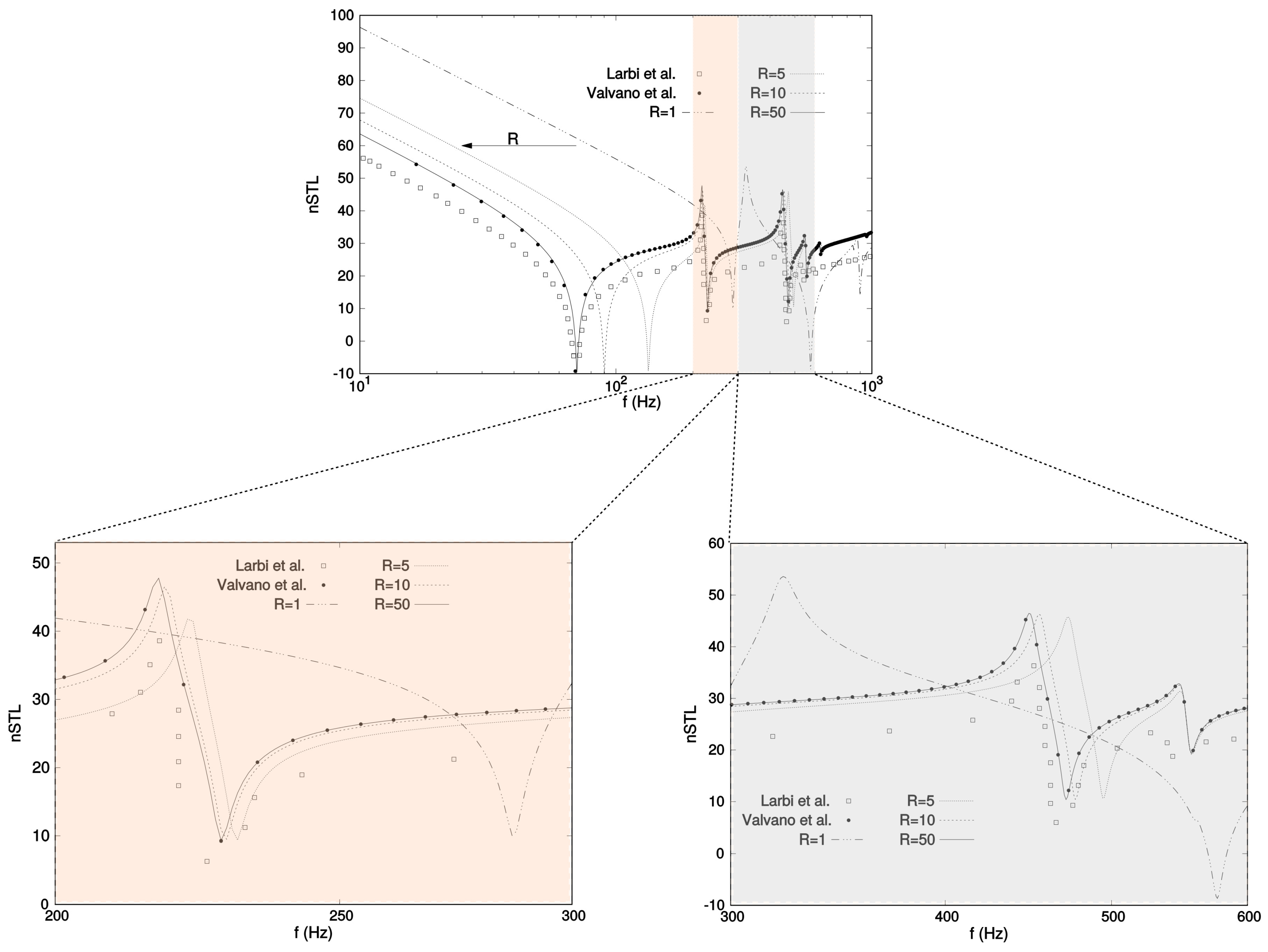
Figure 6.
Cylindrical panel with simply-supported boundary-conditions. 3D-view of the Sound Pressure (Pa) evaluated at different frequencies from the top surface to a radial distance of m.
Figure 6.
Cylindrical panel with simply-supported boundary-conditions. 3D-view of the Sound Pressure (Pa) evaluated at different frequencies from the top surface to a radial distance of m.

Figure 7.
Reference system and geometry of the spherical sandwich viscoelastic shell with metal skins and the transmitted sound pressure field.
Figure 7.
Reference system and geometry of the spherical sandwich viscoelastic shell with metal skins and the transmitted sound pressure field.

Figure 8.
Transmitted sound power level of the rectangular cylindrical and spherical shells with m, for different boundary conditions.
Figure 8.
Transmitted sound power level of the rectangular cylindrical and spherical shells with m, for different boundary conditions.
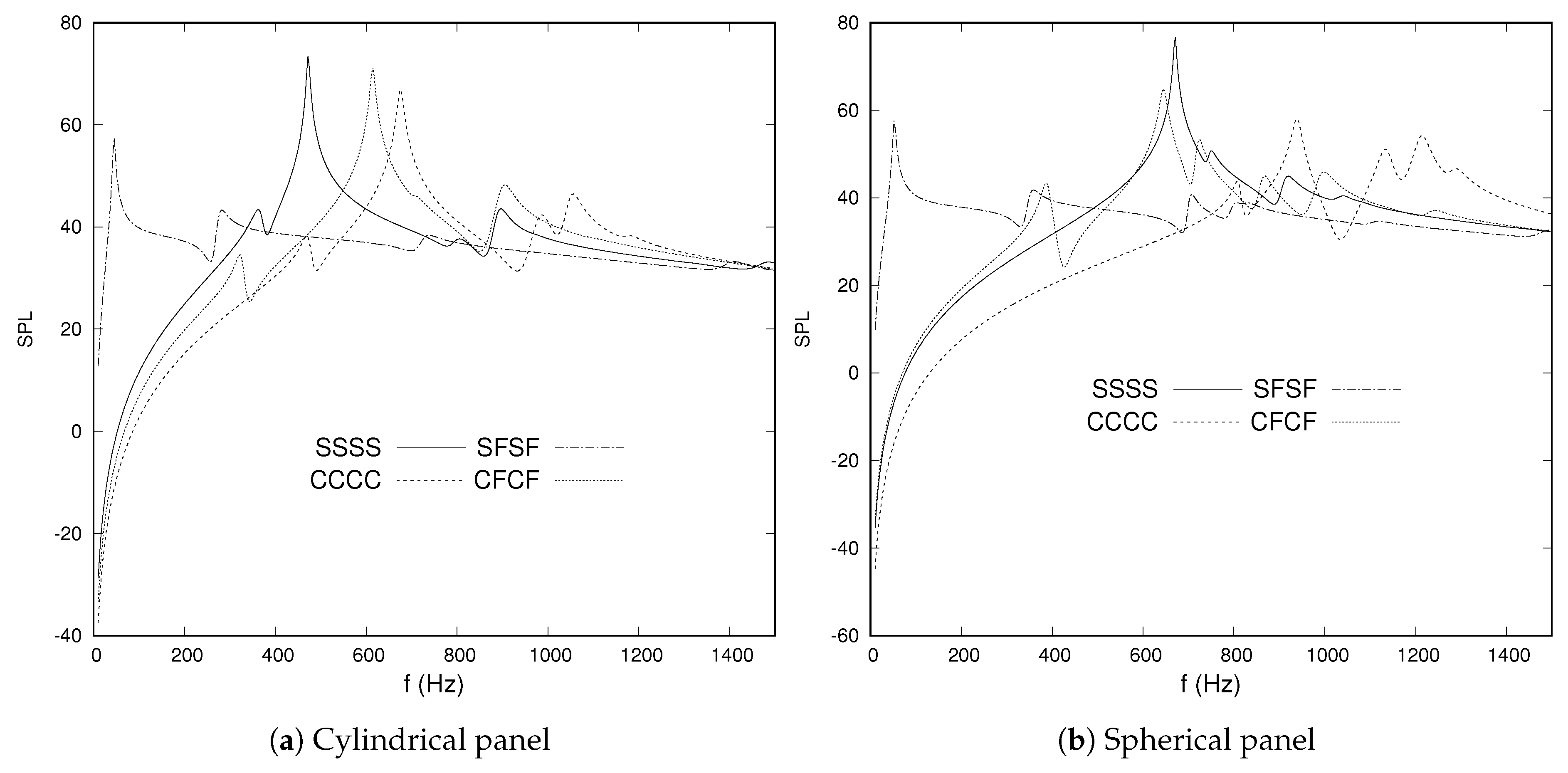
Figure 9.
Transmitted sound power level of the rectangular cylindrical and spherical shells with simply-supported boundary conditions for all the edges, for different mean radii.
Figure 9.
Transmitted sound power level of the rectangular cylindrical and spherical shells with simply-supported boundary conditions for all the edges, for different mean radii.

Figure 10.
Clamped-free rectangular cylindrical and spherical shells with m. Three-dimensional representation of the Sound Pressure (Pa) transmitted by the shell panels at Hz from the top shell surface to a radial distance of m.
Figure 10.
Clamped-free rectangular cylindrical and spherical shells with m. Three-dimensional representation of the Sound Pressure (Pa) transmitted by the shell panels at Hz from the top shell surface to a radial distance of m.

Figure 11.
Transmitted sound power level of the composite cylindrical and spherical shells with viscoelastic core, for different lamination schemes.
Figure 11.
Transmitted sound power level of the composite cylindrical and spherical shells with viscoelastic core, for different lamination schemes.

Figure 12.
Transmitted sound power level of the composite cylindrical and spherical shells with different viscoelastic layer sequences.
Figure 12.
Transmitted sound power level of the composite cylindrical and spherical shells with different viscoelastic layer sequences.

Figure 13.
Composite rectangular cylindrical and spherical shells with m and lamination . Three-dimensional representation of the Sound Pressure (Pa) emitted by the shell panels from the bottom shell surface to a radial distance of 1 m.
Figure 13.
Composite rectangular cylindrical and spherical shells with m and lamination . Three-dimensional representation of the Sound Pressure (Pa) emitted by the shell panels from the bottom shell surface to a radial distance of 1 m.


Table 1.
Geometrical and material data for the simple cylindrical panel.
| a | b | h | E | |||||||
| (mm) | (m) | (mm) | (mm) | (GPa) | (-) | (kg/m3) | (GPa) | (-) | (kg/m3) | (m/s) |
|---|---|---|---|---|---|---|---|---|---|---|
| 350 | 1 | 220 | 1 | 71 | 2814 | 340 |
Table 2.
Geometrical and material data for the isotropic sandwich shells.
| (GPa) | (-) | (kg/m3) | (MPa) | (-) | (-) | (-) | (s) | (-) | (kg/m3) |
|---|---|---|---|---|---|---|---|---|---|
| 71 | 2814 | 1570 | 1300 | ||||||
| (mm) | (m) | (mm) | (m) | (mm) | (mm) | (kg/m3) | (m/s) | ||
| 300 | 1 | 200 | 1 | 340 |
Table 3.
Geometrical and material data for the composite shells.
| (GPa) | (GPa) | (-) | (GPa) | (GPa) | (GPa) | (kg/m3) |
|---|---|---|---|---|---|---|
| 3 | 1543 | |||||
| (m) | (m) | (m) | (m) | (m) | (kg/m3) | (m/s) |
| 3 | 3 | 340 |
Table 4.
Frequency at the first peak (Hz) for the transmitted sound power level of the composite cylindrical and spherical shells with different lamination schemes.
Table 4.
Frequency at the first peak (Hz) for the transmitted sound power level of the composite cylindrical and spherical shells with different lamination schemes.
| Lamination | Cylindrical | Spherical |
|---|---|---|
| 196.8 | 229.7 | |
| 198.8 | 228.8 | |
| 236.7 | 272.7 | |
| 232.8 | 270.7 | |
| 236.7 | 272.7 | |
| 210.8 | 248.7 | |
| 193.8 | 224.3 | |
| 186.8 | 214.2 |
© 2019 by the authors. Licensee MDPI, Basel, Switzerland. This article is an open access article distributed under the terms and conditions of the Creative Commons Attribution (CC BY) license (http://creativecommons.org/licenses/by/4.0/).
Share and Cite
MDPI and ACS Style
Valvano, S.; Alaimo, A.; Orlando, C. Sound Transmission Analysis of Viscoelastic Composite Multilayered Shells Structures. Aerospace 2019, 6, 69. https://doi.org/10.3390/aerospace6060069
AMA Style
Valvano S, Alaimo A, Orlando C. Sound Transmission Analysis of Viscoelastic Composite Multilayered Shells Structures. Aerospace. 2019; 6(6):69. https://doi.org/10.3390/aerospace6060069
Chicago/Turabian StyleValvano, Stefano, Andrea Alaimo, and Calogero Orlando. 2019. "Sound Transmission Analysis of Viscoelastic Composite Multilayered Shells Structures" Aerospace 6, no. 6: 69. https://doi.org/10.3390/aerospace6060069
Note that from the first issue of 2016, this journal uses article numbers instead of page numbers. See further details here.