Article

Effect of a Circular Slot on Hybrid Airship Aerodynamic Characteristics

by
Sekar Mano
1,
RadhaKrishnan Ajay Sriram
1,
Ganesan Vinayagamurthy
2,
Subramania Nadaraja Pillai
1,*,
Amjad Ali Pasha
3,
Dwarshala Siva Krishna Reddy
4 and
Mustafa Mutiur Rahman
5
1
Turbulence and Flow Control Lab, School of Mechanical Engineering, SASTRA Deemed University, Thanjavur 613401, India
2
Center for Innovation and New Product Development, Vellore Institute of Technology, Chennai 600127, India
3
Aerospace Engineering Department, King Abdulaziz University, Jeddah 21589, Saudi Arabia
4
Department of Mechanical Engineering, SRM Institute of Science and Technology, Kattankulathur 603203, India
5
Department of Mechanical and Mechatronics Engineering, University of Waterloo, Waterloo, ON N2L 3G1, Canada
*
Author to whom correspondence should be addressed.
Aerospace 2021, 8(6), 166; https://doi.org/10.3390/aerospace8060166
Submission received: 20 March 2021 / Revised: 6 June 2021 / Accepted: 9 June 2021 / Published: 15 June 2021

Abstract

:
This numerical study reports the aerodynamic properties of a hybrid airship. The hybrid airships were designed by combining two semi-ellipsoids with a semi-discoid as the base model. From the base model, three different geometrics were identified to study their aerodynamic characteristics. A circular slot was provided between the pressure side and the suction side of the airship. The objective of this study was to realize the flow behavior, aerodynamic characteristics, and stability properties of such slotted hybrid flying vehicles. Interestingly, the results imply that the lift coefficient increases with an increase in the angle of attack for the slotted configurations; this is because the flow separation is delayed due to the slot opening, which in turn is due to the flow of energies from the high-pressure region to the bottom through the slots. The delayed stall angle was 50 degrees, which was 10% more than that of the base model. Aerodynamic characteristics are discussed based on surface pressure, coefficient of lift, and coefficient of drag for various slotted hybrid airships.

1. Introduction

Airship technology is progressing and has versatile applications such as endurance, survivability, cargo, weather monitoring, early warning systems, communication relays, meteorological surveillance, space exploration. Remote controlled airships are used for Wi-Fi transmission, border surveillance, forest animal surveillance, etc. Therefore, airship aerodynamic analyses are of primary interest to researchers [1]. High altitude airships’ aerodynamic behavior near space and their applications are most important for researchers. In general, the aerostatic lift has no lift dependent on components, since helium gas is used to generate lift from buoyant force in such lighter-than-air (LTA) vehicles. There are also propulsion systems to overcome drag and control devices to provide multi-axis stability.
Various researchers have made attempts to ameliorate the design of airships to have better aerodynamics and stability characteristics. Experimental investigations on LOTTE, a remote controlled airship, were optimized for the lowest drag coefficient, which is about 11.1% lower than normal. Ma et al. [2], Kale et al. [3], and Zhao et al. [4] made a generic algorithm of various balloon shapes and methodologies to estimate the coefficient of drag as a function of airship envelope geometry. In addition, Andan et al. [5] proposed a hybrid airship design with a wing that increases the lift force threefold at positive angles of attack due to aerodynamic forces. Sun et al. [6] reported the aerodynamic and stability characteristics of the entire flight path of the stratospheric airship. A numerical investigation for a discoid shape with slots was performed by Cimarelli et al. [7], who found that the stall delays until 55° angle of attack and that the airship has better longitudinal stability with this shape. Likewise, to reduce the drag on the airship, Fei and Zhengyin [8] conducted a numerical investigation to derive the optimum position and diameter of the propulsive devices. Wang [9] then proposed a new mechanism of introducing different cup shapes to reduce the drag coefficient for a stratospheric airship. An experimental investigation of a stratospheric airship performed by introducing micro vortex generators (MVG) at the rear end of the airship was reported by Yi et al. [10] to reduce the drag.
P. Liu et al. [11] reported on a stratospheric airship hull that was designed by using the Michel transition law technique, and their results confirmed a lower drag coefficient while the pitch angle reaches between ±15°. Dumas et al. [12] proposed a novel shape by optimizing the airship in a way that utilizes a function of changing the volume for altitude; this airship shape ensured an effective drop of the required power for propulsion in the lower parts of the atmosphere. Ram and Pant [13] suggested an airship shape compared with a GNVR airship; this airship shape led to the optimum shape of the airship envelope and maximized its payload. Irfan and Pant [14] generated a high-altitude airship (HAA) optimized by considering parameters such as envelope shape, size, payload, power system requirements, and altitude. However, there is limited study on reducing the drag coefficient in the hybrid airship. We propose hybrid airships with various circular slot thicknesses, which improve the aerodynamic characteristics by balancing pressure force. A detailed summary of existing works on airship design performance and stability is shown in Table 1.
A novel modified airship with a slot was identified to improve aerodynamic performance. The objective of this present research was first to report numerical studies of the aerodynamic characteristics of hybrid airships with different configurations. Then, the hybrid airship model was subjected to various crosswind angles, and envelope characteristics were analyzed. Finally, the flow around the airship model was investigated to give general physical meaning to the behavior of the aerodynamic coefficient. Based on the flow topology, the changes in aerodynamic characteristics were explained.

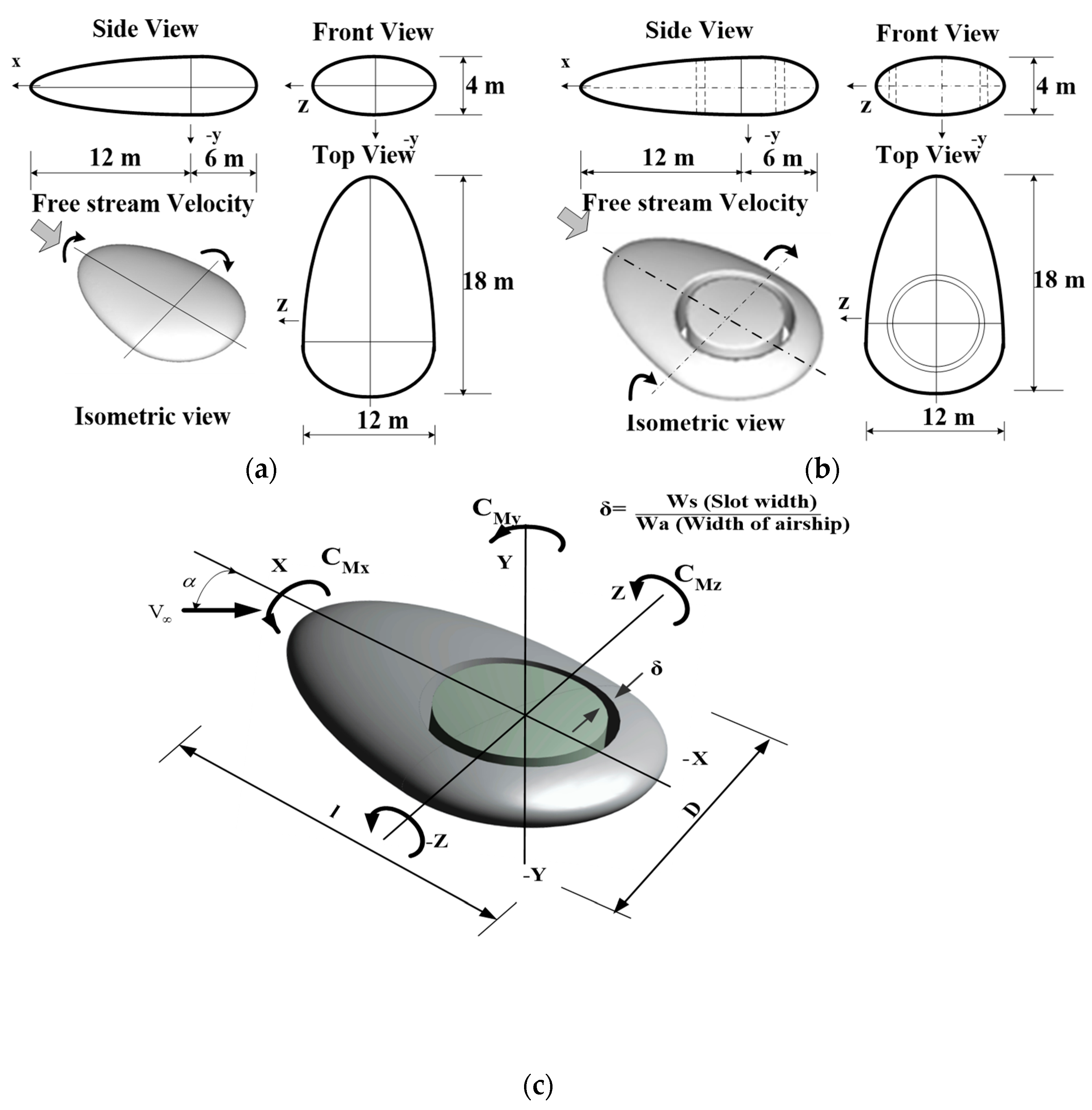
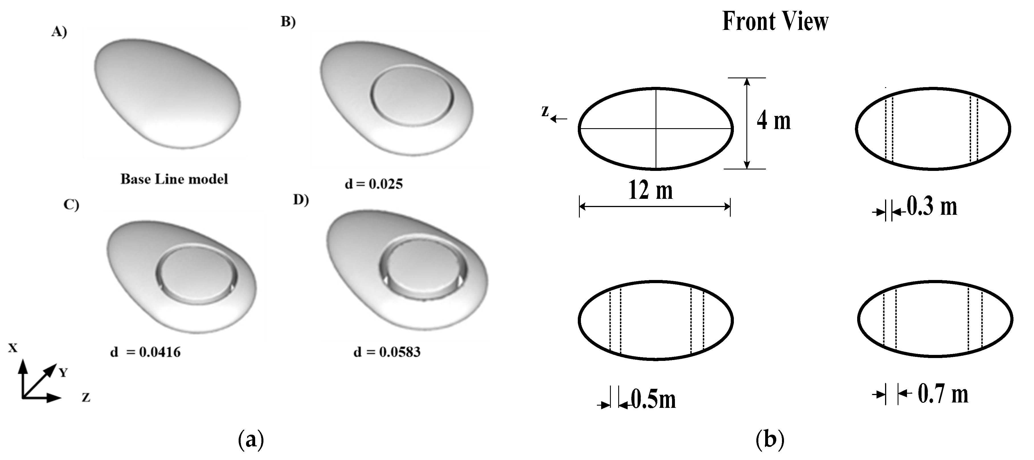
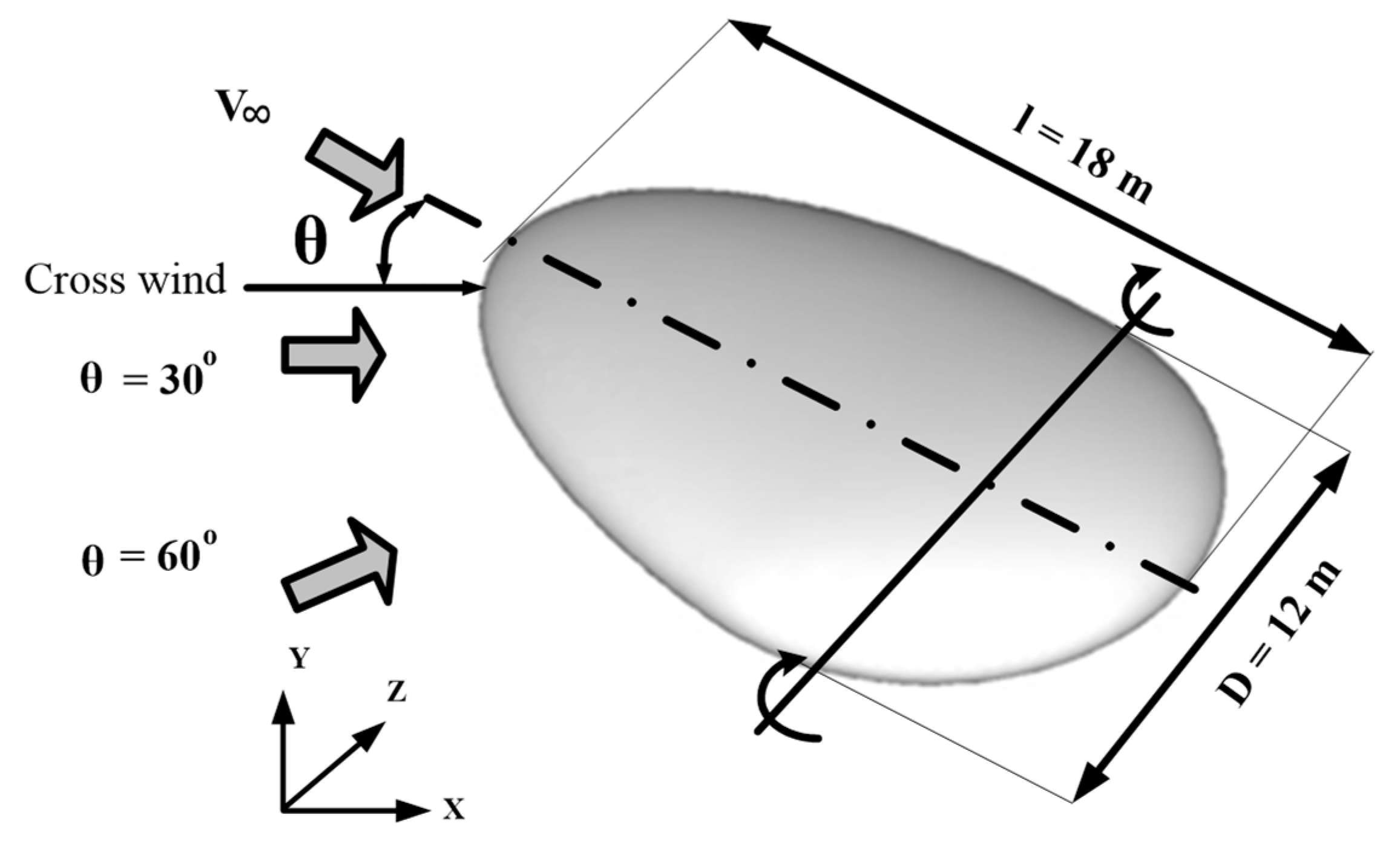
2. Airship Model and Configuration Feature

The optimization study on hybrid airship shapes carried out by Ceruti et al. [17] used different ratios to define the semi-ellipsoid geometry. The purpose of the present investigation was to consider the combined configuration of two semi-ellipsoid shapes and one semi-disc shape. This airship model had a height of 4 m., and its width and length were set at 6 m and 18 m, respectively. As shown in Figure 1a, a circular slot opening was introduced to improve the aerodynamic characteristics.
Figure 2a,b shows that the slotted models had different widths in each case. The outer radius of the circular slot was fixed at a 4 m radius, and the inner radius varied based on the slot width. The slot widths considered were 0.3 m, 0.5 m, and 0.7 m. A non-dimensional number, circular slot ratio, is introduced as:
Circular slot ratio (δ) = (Slot width)/(width of the airship),
The first model (hereafter referred to as the baseline model), which does not have any slot, and the other geometrical models, with circular slot ratios (δ) of 0.025, 0.0416, and 0.0583, were also modeled using Solid works.

3. Details of Computational Methodology
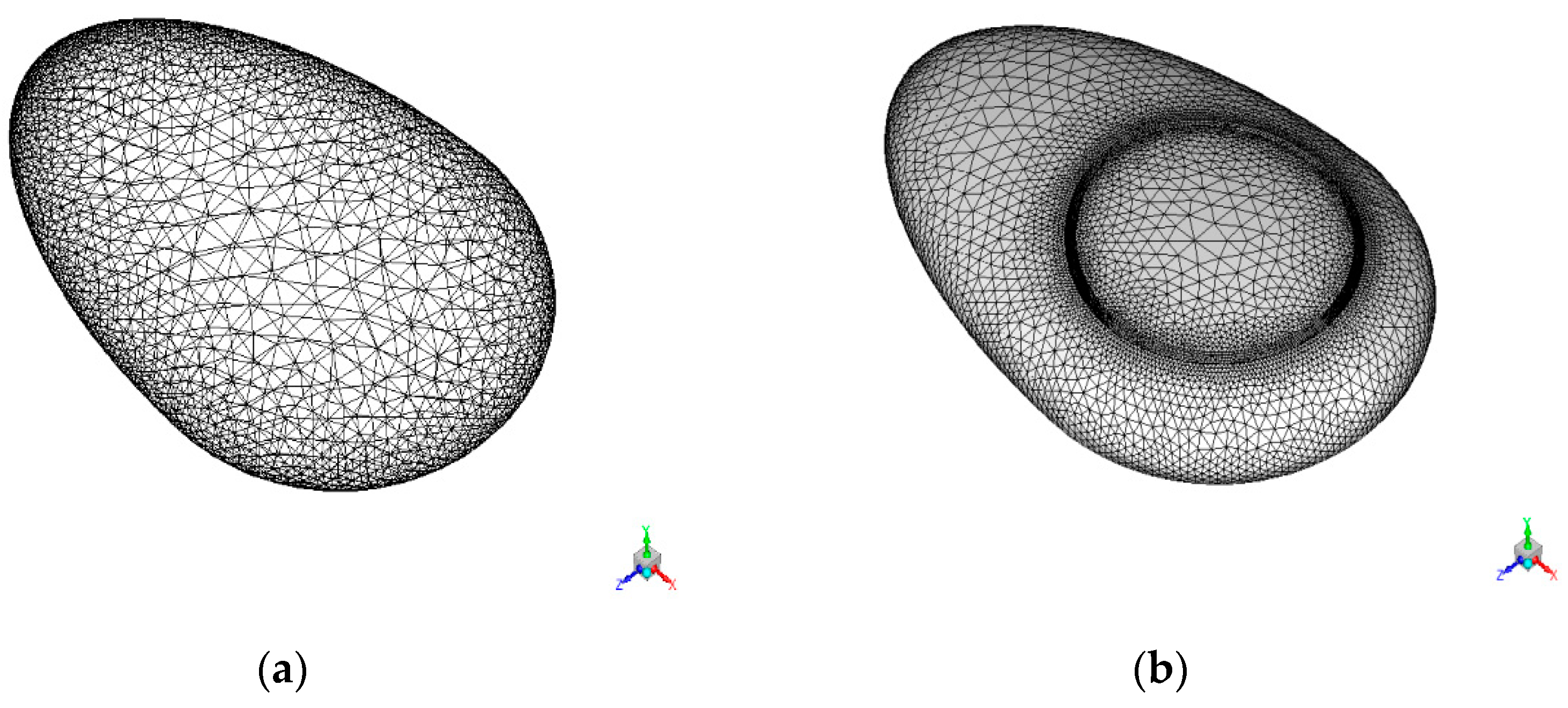
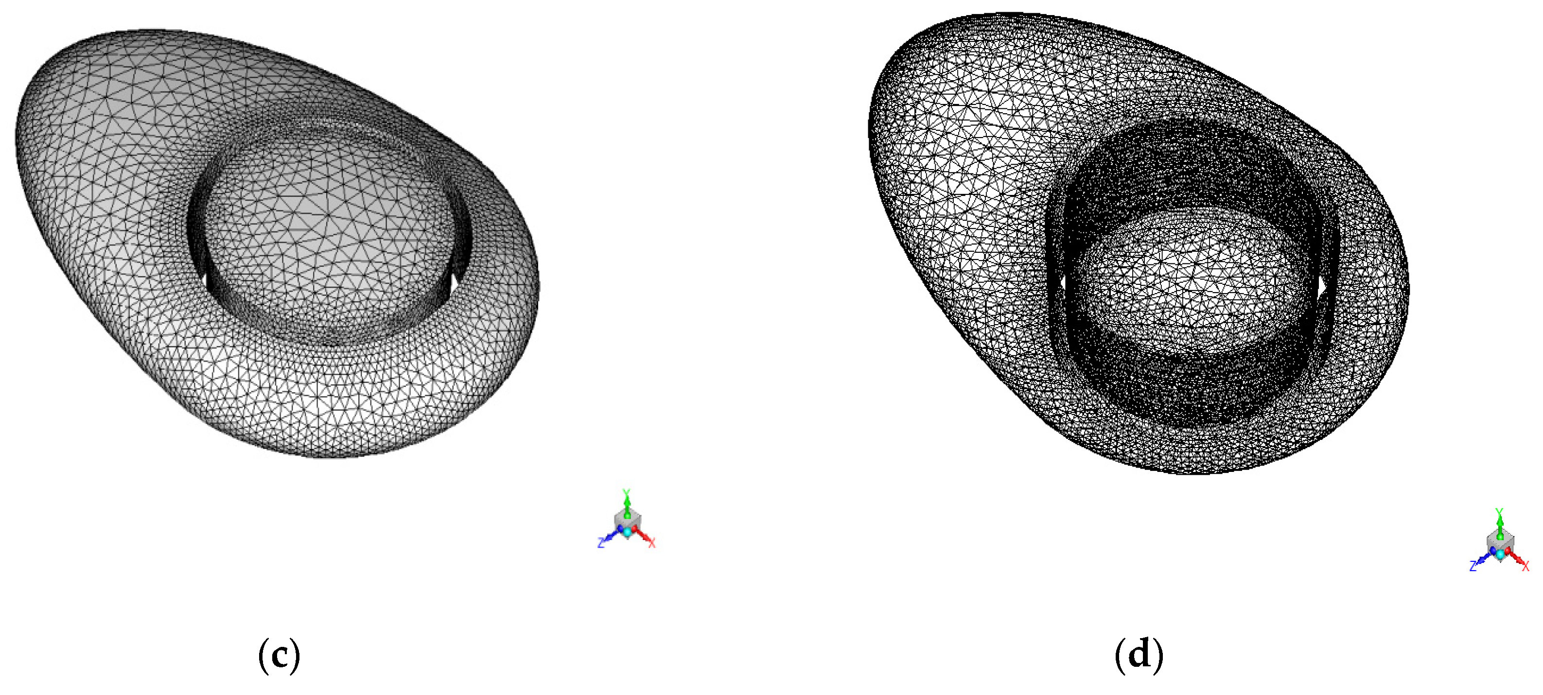
3.1. Meshing

The objective of this computational study was to solve the wall-bounded flows of comparatively small pressure gradients. The computational domain was chosen to be large enough as not to interfere with the aerodynamic properties of the simulated airship. In these cases, the model was initially considered at the 0° angle of attack. The total number of mesh elements chosen was around 0.4 million cells. Hybrid tetra/hexahedral elements were employed.

3.2. Simulation Method

The computation was performed by solving the incompressible Reynolds averaged Navier–Stokes (RANS) equations [6], which were discretized using the finite volume method, using ANSYS Fluent package. The SIMPLE method of pressure velocity coupling was chosen, and the second-order upwind model was chosen for solving the momentum equation. The turbulence model adopted was the standard k-ϵ model, a two-equation model that includes transport equations for turbulent kinetic energy k and dissipation rate ϵ, subsequently addressing the turbulent properties of the flow. The RANS equations for an incompressible turbulent flow are expressed as follows.
Continuity:
u ¯ i x i = 0
Momentum equation:
u ¯ i x t + u ¯ j u ¯ i x j = 1 ρ p ¯ x i + ν 2 u ¯ i x i x j x i u ¯ i u ¯ j = 0
The standard k-ε model used in the present simulations for turbulence closure is given by:
u ¯ j k x j = τ i j u ¯ i x j ε + x j υ + υ T σ k T k x j
u ¯ j ε x j = C ϵ 1 ε k τ i j u ¯ i x j C ϵ 2 ε 2 k + x j υ + υ T σ k ε ε x j
For more information about this model, see [6]. The constants of the model were:
σk = 1, Cε1 = 1.44, Cε2 = 1.92, and σε = 1.3.

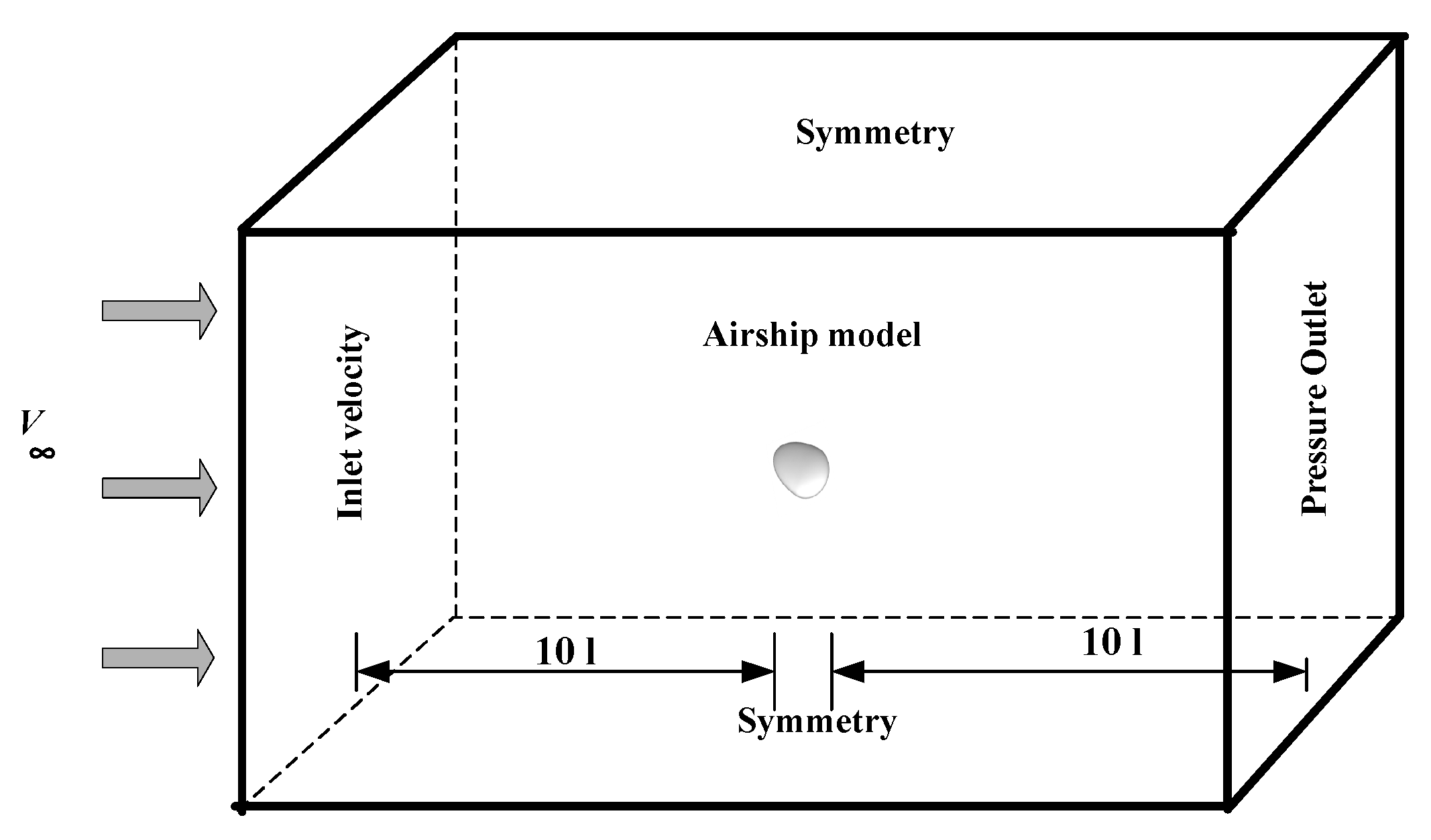
3.3. Computational Domain

Figure 3 shows the cubic computational domain used for the current study. The boundary condition of the present study for each face was given such that the face through which flow enters the domain was given as a velocity inlet with a magnitude of V = 5 m/s, and the pressure outlet was given by the values of standard atmospheric conditions as shown in Table 2. The meshes used for the airship model in the current work are shown in Figure 4. The rest of the faces and the model were given symmetry boundary conditions. Once the numerical setup was defined, the pressure-based solver was used to solve the RANS equations.

3.4. Grid Independence Study

The grid independence test was carried out for multiple sets of grids of 0.1 to 0.5 million elements. Figure 5 shows estimated aerodynamic forces for the hybrid airship for various grids at 0° angle of attack. Based on the grid independence study, the computational domain was discretized with approximately 0.4 million hybrid tetra/hexahedral elements.

4. Result and Discussion

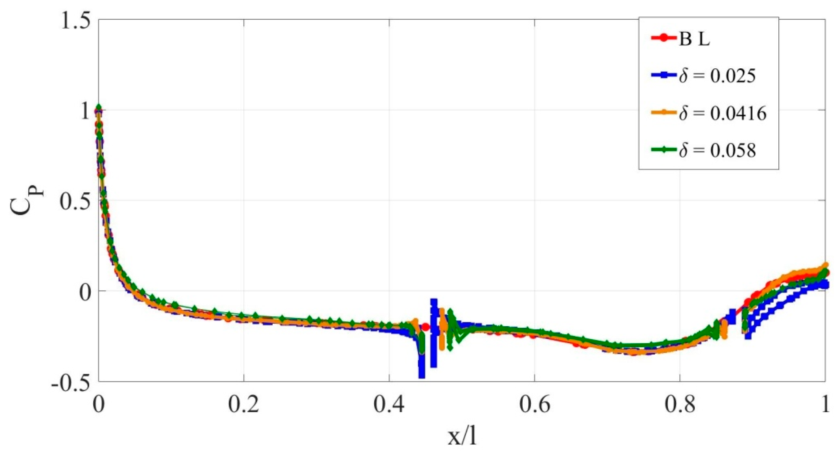
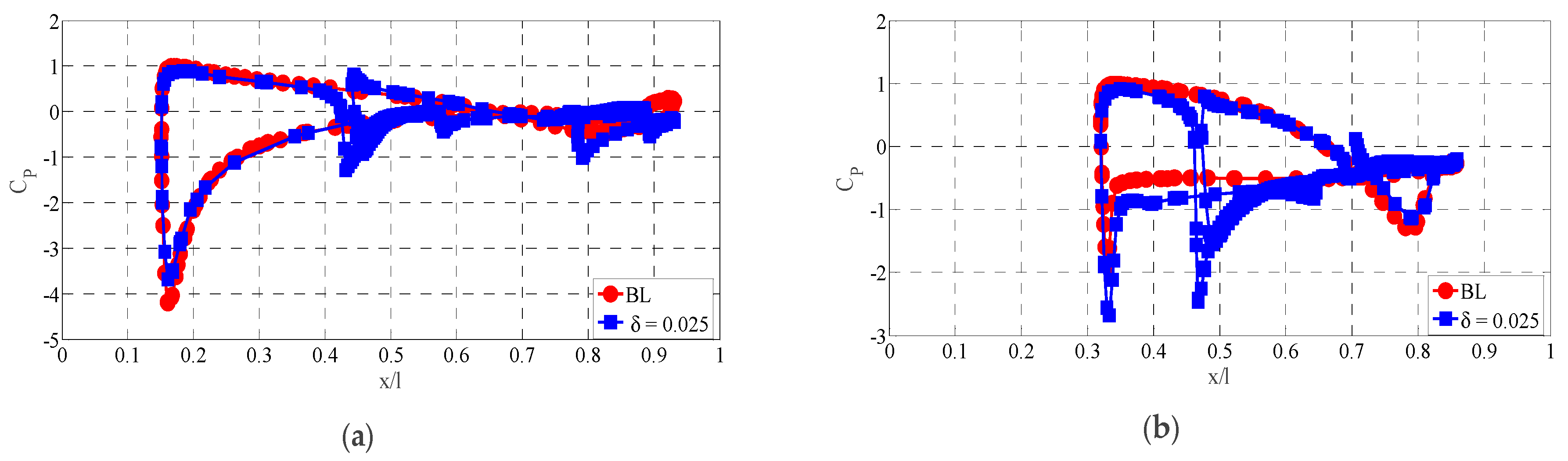
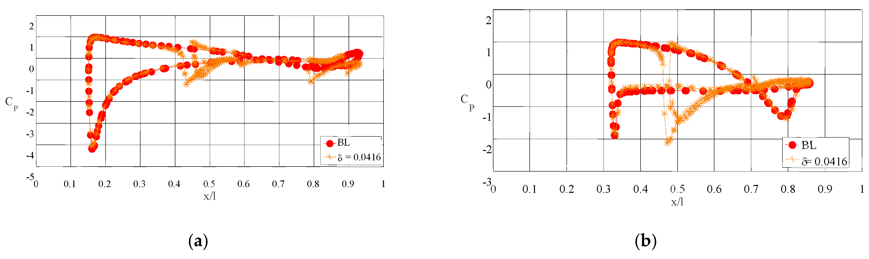
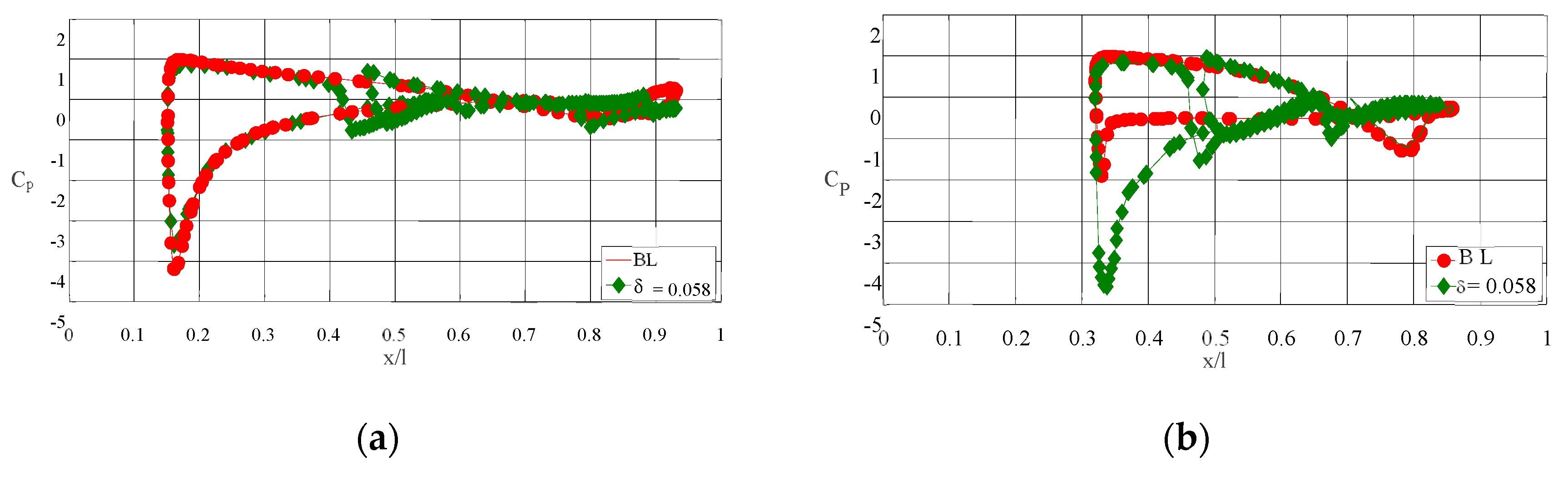
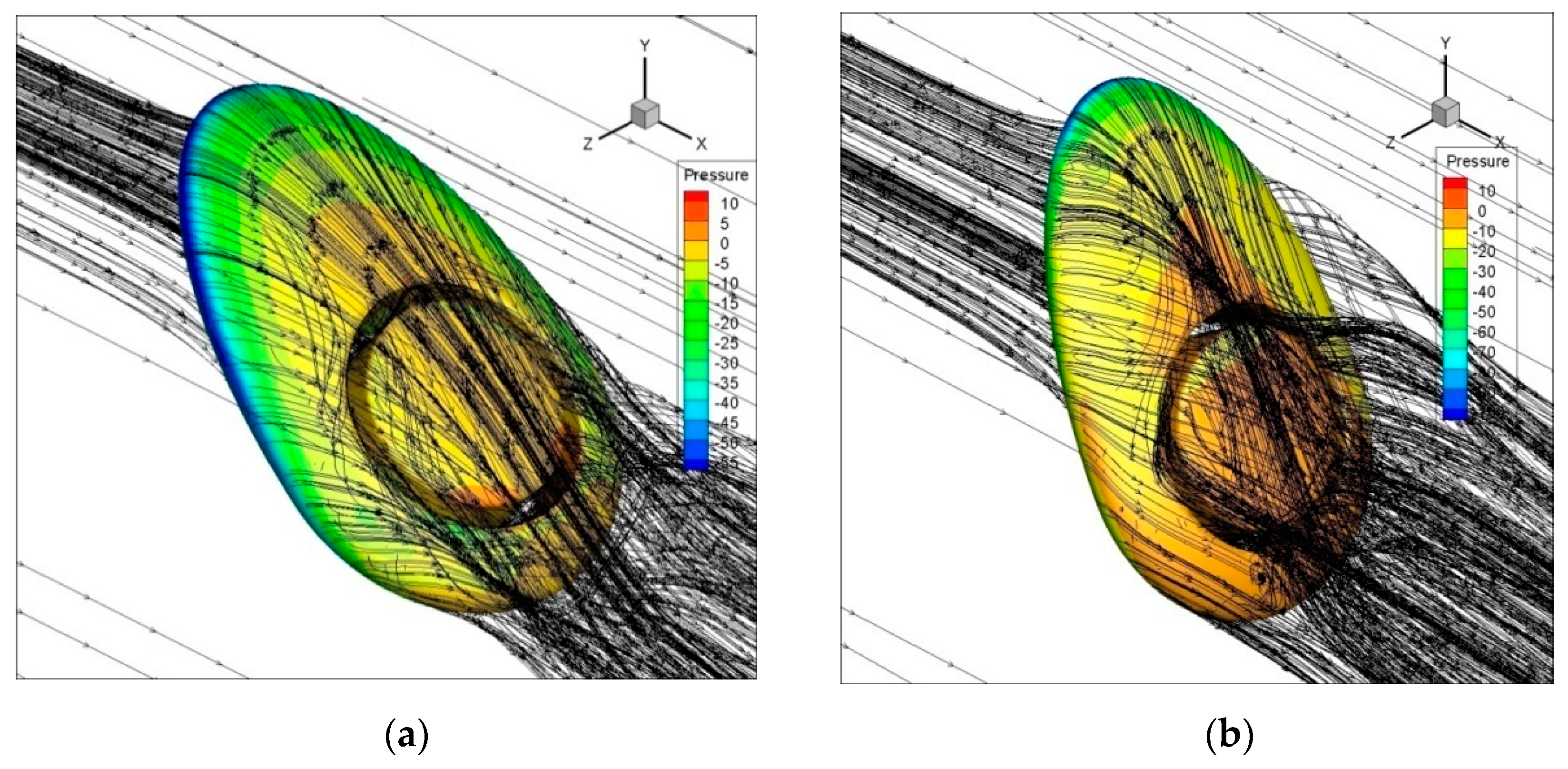
4.1. Pressure Characteristics over an Airship

Figure 6 represents the variation of coefficient of pressure (CP) for dimensionless chord length parameter x/l. Generally, the coefficient of pressure over a surface can be defined as:
CP = (PP)/(0.5 × ρ × V2),
Here, P represents the freestream static pressure, P represents the local static pressure acting over the airship model, and V is the free stream velocity.
Figure 6 depicts the variation of pressure coefficient for the length of the hybrid airship. In this figure, at α = 0°, hybrid airships with and without slot openings subjected to a free stream velocity V = 5 m/s show equal pressure distribution between the pressure side and suction side. For all the δ values, the pressure distribution shows a similar trend. However, at the location of the slot, the pressure distribution shows an insignificant change. In one of the airship models considered in the present study (δ = 0.025), the stall occurred at 50°, as is evident from Figure 10. Hence, the pressure distribution before and after stall is extensively discussed.
Figure 7a,b represents the pre-stall and post-stall regime pressure distribution over the airship at δ = 0.025 for α = 40° and α = 60° respectively. At α = 40°, the pressure distributions of the airship at δ = 0.025 and the baseline (BL) model show a slightly significant difference. However, at α = 60°, i.e., the post-stall region, the pressure coefficient under the curve that is along the length is slightly larger, leading to an increased form of drag. A similar trend is observed for α = 40° and α = 60°, respectively, at δ = 0.0416 in Figure 8. In the case of the circular slot ratio δ = 0.0583, the pressure difference is significant from the leading edge itself, as shown in Figure 9b for α = 60°. Usually, the high-pressure region on the bottom and the low-pressure region on the top of the airship are responsible for the aerodynamic characteristics. The circular slot modifies the pressure distribution and enhances the aerodynamic characteristics. That is, the high-pressure region sweeps through the slot and increases the momentum on the top surfaces, which is the reason for delaying the flow separation. In Figure 9a, it is visible that the effect of the slot appears even from the leading edge itself and modifies the pressure distribution throughout the body.

4.2. Analysis of the Aerodynamic Parameters

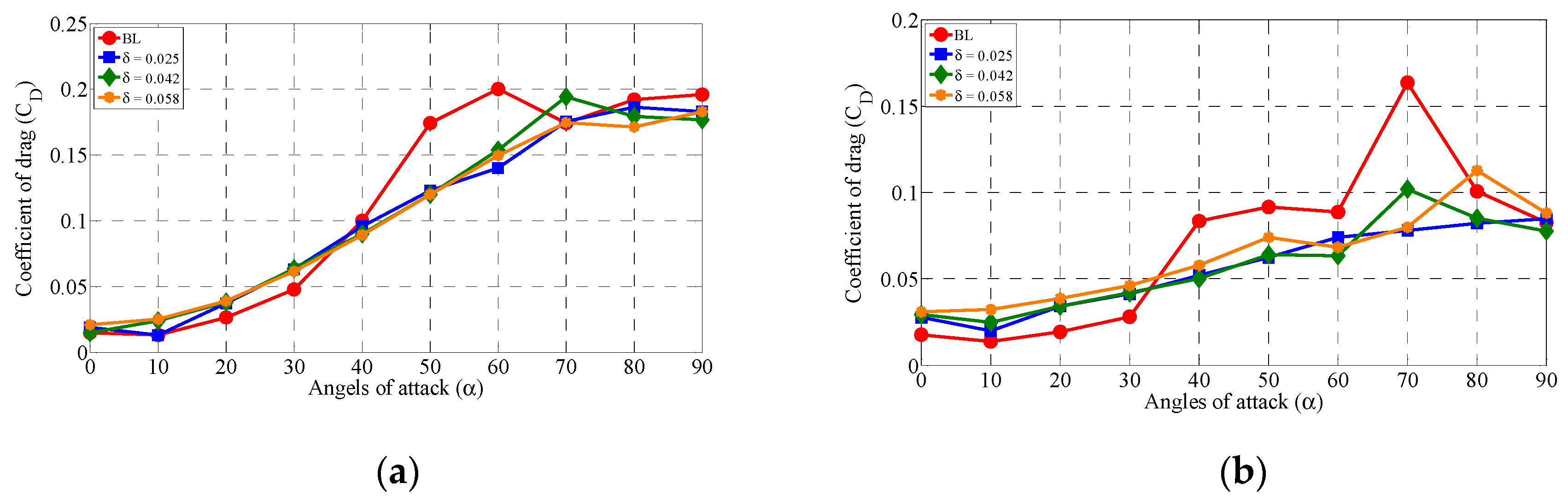
4.2.1. Lift and Drag

The coefficients of lift and drag for the hybrid airship model are shown in Figure 10a,b, respectively, for the angles of attack α = 0 to 90°. The lift coefficient was calculated based on
CL = L/(0.5 × ρ × V2 × S).
The lift coefficient for the baseline model (without a slot) was found to be higher than those of the airships with slots. This difference is because of the high pressure created on the frontal surface area of the slotless baseline model compared to the models with slots. For the most part, the lift force is created because of the pressure contrast between the windward side and the leeward side. On the low-pressure windward side, the stream quickens and gets separated at a point along with the internal boundary layer due to the formation of the adverse pressure gradient. The lift coefficient increases up to α= 40°, where it reaches its maximum value at CL = 0.275. After this, the baseline model stalls at αmax= 40°. Similarly, for δ = 0.025 and δ = 0.0583, lift increases from α = 0 to 50°, where it reaches its maximum value at CL = 0.19 (δ = 0.025) and CL = 0.18 (δ = 0.0583), respectively. For δ = 0.0416, lift increases up to α = 0–40°, where it reaches its maximum at CL = 0.15. Stalling is a phenomenon that occurs when the pressure gradient is too high, such that a pressure force overcomes the fluids’ inertial forces and the flow departs from the model contour. This process results in a sudden decrease in the lift. The stalling angle of the baseline model without a slot was found to be 40°, which is smaller than those of the models δ = 0.025 and δ = 0.0583, which reached 50° stalling. Because of the introduction of the slot in δ = 0.025 and δ = 0.0583, this result shows a 10° stall delay. This is a very interesting result, peculiar to the hybrid airship with slots.
CD = D/(0.5 × ρ × V2 × S)
Drag studies were carried out to design the most efficient aerodynamic envelope. The baseline model, until a 20-degree angle of attack, shows reduced drag when compared to the slotted ones. However, the baseline drag coefficient starts increasing after a 20-degree angle of attack, which is evident from Figure 10. The drag coefficient (CD) increases with the angle of attack. In the models δ = 0.025 and δ = 0.0583, the drag coefficient is much lower than that of the base model. In δ = 0.0416, the drag coefficient is even lower. Comparing the baseline model with the slotted models, the baseline model creates more drag while increasing the angle of attack. This rise in drag force value also affects the aerodynamic efficiency of the body, as is evident in Figure 10. At higher angles of attack, wake vortices are generated at the trailing edge due to flow as well as boundary layer separation that in turn builds drag as well as lift force. The present work shows which model is more efficient at high altitudes. The stall delay characteristics are achieved at the cost of a higher drag envelope with a good amount of aerodynamic efficiency.

4.2.2. Effect of Crosswind on Airship V

Figure 11 shows the schematic diagram of an airship with crosswind angles. It highlights the correlation of aerodynamic force coefficients with increasing angles of attack for the crosswind directions of θ = 30° and 60° for the airship models with and without slots.
Figure 12 and Figure 13 depict crosswind angles of θ = 30° and 60° with increasing angles of attack from α = 0° to α = 90°, and the impact of these angles on variation of the lift and drag forces. When the hybrid airship model is subjected to a crosswind angle of θ = 30°, which is basically on the lower surface, the pressure side creates high pressure, whereas the top surface suction side shows less pressure (Figure 12a). Due to this pressure difference, the flow tries to move from the pressure side to the suction side, hence producing lift force. The same situation happens in the baseline model. It shows a lift coefficient increase to a maximum of CLmax= 0.29 at α = 40°, and after this, the flow gets separated and the lift starts to decrease with increasing angles of attack. For the models with slots δ = 0.025, δ = 0.0416, and δ = 0.0583, the lift coefficient gradually increases with increasing angles of attack. At α = 50°, due to the slot opening, the flow tries to move from the pressure side to the suction side. The flow is mixed with the separated flow, and this phenomenon delays the stall by almost 10°. The main effect of the opening is the reduction of the lift coefficient intensity, the maximum values of which are CLmax= 0.154, 0.147, and 0.137, respectively for δ = 0.025, δ = 0.0416, and δ = 0.0583 at α = 50°. Similarly, Figure 12b shows a crosswind angle of θ = 60° for the baseline model (without a slot), where the lift coefficient increases to a maximum of CLmax= 0.162 at α = 40°. After this, the flow gets separated, and lift decreases with increasing angles of attack. For the circular slot ratios δ = 0.025, δ = 0.0416, and δ = 0.0583, the lift coefficients increase up to α = 50° and reach their maxima at CLmax= 0.0766, 0.0841, and 0.0864, respectively.
Figure 13a,b represents the behavior of the drag coefficient (CD) as a function of the angle of attack (α) for the four different configurations. Once more, the investigation began by considering the straightforward instance of the carrier model with and without opening. The variation of lift and drag forces were studied while the crosswind angle was at θ = 30° and θ = 60° with increasing angles of attack from α = 0° to α = 90°. Considering the drag coefficient at pre-stall, the base model shows less drag compared to the slot models. However, the base model shows high drag at the post-stall region. When flow passing through the opening undergoes a weak acceleration and deviation while traversing the opening, it leads to the blockage of flow and reduction of drag. Hence, this effect leads to drag reduction in the slotted airship model compared to the base model.

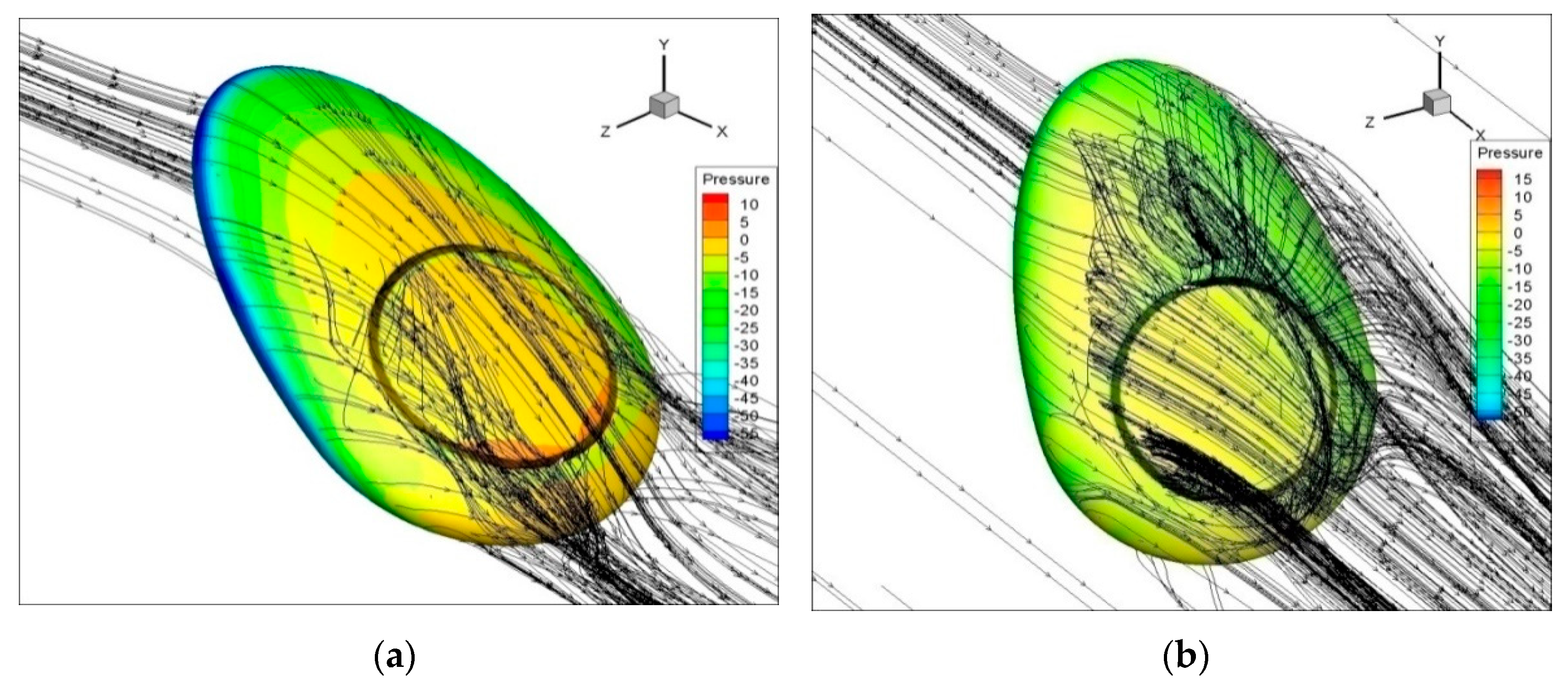
4.2.3. An Effect of the Slot Opening and Flow Topology

Figure 14, Figure 15 and Figure 16 depict the aerodynamic properties of hybrid airships with slots where the flow field is described based on the streamline flow pattern. Here, the flow topology of the pre-stall region and post-stall region is described at α = 40° and α = 60° for hybrid airship with slots. In the pre-stall region, when the airship reaches α = 40°, it shows attached flow over the suction side, and after some point, it shows flow separation. Indeed, the flow of air from the bottom to the upper surface energizes the upper boundary layer, allowing it to maintain attached to the surface. At the post-stall region, from the velocity field, it can be observed that the flow field tends to turn around in the hybrid airship models with slots, moving from the pressure side to the suction side. Hence, it forms a strong coherent trailing vortex downstream of the airship model. This phenomenon reaches higher values for maximum angle of attack; hence, the flow gets stalled at α = 50° for δ = 0.025, δ = 0.0416, and δ = 0.0583. In δ = 0.0583, a very strong coherent trailing vortex appears downstream of the airship model.

5. Conclusions

The numerical investigations using RANS were performed to estimate the aerodynamic characteristics of hybrid airship models with and without slot openings. Various angles of attack from 0 to 90° in increments of 10° were considered, and corresponding aerodynamic characteristics were inferred. The following conclusions were made based on the above study.
  • The introduction of the slot openings made the stall angle increase by 10%, from α = 40° for the baseline model to α = 50° for the slotted models, except for the model δ = 0.041, which showed the same separation point as the baseline.
  • When the flow passes through the slots, it increases the momentum on the upper surface and hence leads to a delay of the flow separation, which decreases the drag.
  • An increase in circular slot ratio modifies the pressure distribution significantly, such that it contributes to enhancing the aerodynamic characteristics of hybrid airships.
  • Considering all parameters, the circular slot ratios of δ = 0.025 and δ = 0.0583 were observed to perform better as compared to the baseline model and the model with δ = 0.0416.
  • The flow topology shows that before stalling, the flow from the pressure side to the suction side of the hybrid airship through the slot is smooth. It becomes irregular and chaotic in the after-stall region of angle of attack α = 60°, as observed.

Author Contributions

Conceptualization, S.N.P., S.M., A.A.P. and G.V.; methodology, S.N.P., A.A.P. and R.A.S.; software, S.M., R.A.S.; validation, S.M., R.A.S., D.S.K.R. and M.M.R.; formal analysis, S.M., R.A.S.; investigation, S.M., R.A.S. and S.N.P.; resources, S.N.P., A.A.P.; data curation, S.M., R.A.S.; writing—original draft preparation, S.M., A.A.P. and S.N.P.; writing—review and editing, S.M., S.N.P. and A.A.P.; supervision, S.N.P., A.A.P., M.M.R.; project administration, S.N.P., A.A.P.; funding acquisition, S.N.P. All authors have read and agreed to the published version of the manuscript.

Funding

“Research and Modernization fund, SASTRA Deemed to be University”, grant number R&M/0035/SoME-008/2015-16.

Institutional Review Board Statement

Not Applicable.

Informed Consent Statement

Not Applicable.

Acknowledgments

This work was supported by the “Research and Modernization fund, SASTRA Deemed to be University”, grant number R&M/0035/SoME-008/2015-16. The authors thank SASTRA Deemed to be University for its financial assistance in performing a study of the effect of circular slot openings on hybrid airship aerodynamic characteristics.

Conflicts of Interest

The authors declare no conflict of interest.

References

  1. Dumas, A.; Trancossi, M.; Madonia, M.; Giuliani, I. Multibody advanced airship for transport. SAE Tech. Pap. 2011. [Google Scholar] [CrossRef]
  2. Ma, D.; Li, G.; Yang, M.; Wang, S.; Zhang, L. Shape optimization and experimental research of near space airship. Proc. Inst. Mech. Eng. Part G J. Aerosp. Eng. 2019, 233, 3589–3602. [Google Scholar] [CrossRef]
  3. Kale, S.M.; Joshi, P.; Pant, R.S. A generic methodology for determination of drag coefficient of an aerostat envelope using CFD. In Proceedings of the Collection of Technical Papers—AIAA 5th ATIO and the AIAA 16th Lighter-than-Air Systems Technology Conference and Balloon Systems Conference, Arlington, VA, USA, 26–28 September 2005; Volume 3, pp. 1361–1376. [Google Scholar] [CrossRef] [Green Version]
  4. Zhao, S.; Liu, D.; Zhao, D.; Wu, G.; Yin, S.; Zhou, P. Change rules of a stratospheric airship’s envelope shape during ascent process. Chin. J. Aeronaut. 2017, 30, 752–758. [Google Scholar] [CrossRef]
  5. Andan, A.D.; Asrar, W.; Omar, A.A. Investigation of aerodynamic parameters of a hybrid airship. J. Aircr. 2012, 49, 658–661. [Google Scholar] [CrossRef]
  6. Launder, B.E.; Spalding, D.B. The numerical computation of turbulent flow computer methods. Comput. Methods Appl. Mech. Eng. 1974, 3, 269–289. [Google Scholar] [CrossRef]
  7. Sun, X.Y.; Li, T.E.; Lin, G.C.; Wu, Y. A study on the aerodynamic characteristics of a stratospheric airship in its entire flight envelope. Proc. Inst. Mech. Eng. Part G J. Aerosp. Eng. 2018, 232, 902–921. [Google Scholar] [CrossRef]
  8. Cimarelli, A.; Madonia, M.; Angeli, D.; Dumas, A. Aerodynamic study of advanced airship shapes. J. Aerosp. Eng. 2017, 30, 04016087. [Google Scholar] [CrossRef]
  9. Fei, X.; Zhengyin, Y. Drag reduction for an airship with proper arrangement of propellers. Chin. J. Aeronaut. 2009, 22, 575–582. [Google Scholar] [CrossRef] [Green Version]
  10. Wang, X.L. Investigation of the drag characteristics of stratosphere airships for different cusp shapes. J. Aircr. 2012, 49, 151–160. [Google Scholar] [CrossRef]
  11. Xin-kai, L.; Wei, L.; Ting-jun, Z.; Pei-ming, W.; Xiao-dong, W. Analysis of the effect of vortex generator spacing on boundary layer flow separation control. Appl. Sci. 2019, 1, 5495. [Google Scholar] [CrossRef] [Green Version]
  12. Liu, P.; Fu, G.Y.; Zhu, L.J.; Wang, X.L. Aerodynamic characteristics of airship Zhiyuan-1. J. Shanghai Jiaotong Univ. Sci. 2013, 18, 679–687. [Google Scholar] [CrossRef]
  13. Dumas, A.; Trancossi, M.; Madonia, M.; Pascoa, J.; Ilieva, G.; Coppola, A. CFD analysis and optimization of a variable shape airship. In Proceedings of the ASME International Mechanical Engineering Congress and Exposition, Proceedings (IMECE), Houston, TX, USA, 9–15 November 2012; Volume 7, pp. 161–166. [Google Scholar] [CrossRef]
  14. Ram, C.V.; Pant, R.S. Multidisciplinary shape optimization of aerostat envelopes. J. Aircr. 2010, 47, 1073–1076. [Google Scholar] [CrossRef]
  15. IrfanAlam, M.; Pant, R.S. A methodology for conceptual design and optimization of a high altitude airship. In Proceedings of the AIAA Lighter-Than-Air Systems Technology (LTA) Conference, Daytona Beach, FL, USA, 1–8 March 2013. [Google Scholar] [CrossRef]
  16. Lutz, T.; Wagner, S. Drag reduction and shape optimization of airship bodies. In Proceedings of the 12th Lighter-Than-Air Systems Technology Conference, San Francisco, CA, USA, 3–5 June 1997; Volume 35, pp. 200–210. [Google Scholar] [CrossRef] [Green Version]
  17. Funk, P.; Lutz, T.; Wagner, S. Experimental investigations on hull-fin interferences of the LOTTE airship. Aerosp. Sci. Technol. 2003, 7, 603–610. [Google Scholar] [CrossRef]
  18. Ceruti, A.; Voloshin, V.; Marzocca, P. Heuristic algorithms applied to multidisciplinary design optimization of unconventional airship configuration. J. Aircr. 2014, 51, 1758–1772. [Google Scholar] [CrossRef]
  19. Verma, A.R.; Sagar, K.K.; Priyadarshi, P. Optimum buoyant and aerodynamic lift for a lifting-body hybrid airship. J. Aircr. 2014, 51, 1345–1350. [Google Scholar] [CrossRef]
  20. Zhang, L.; Lv, M.; Meng, J.; Du, H. Optimization of solar-powered hybrid airship conceptual design. Aerosp. Sci. Technol. 2017, 65, 54–61. [Google Scholar] [CrossRef]
  21. Chen, G.; Chen, B.; Li, P.; Bai, P.; Ji, C. Study of aerodynamic configuration design and wind tunnel test for solar powered buoyancy-lifting vehicle in the near-space. Procedia Eng. 2015, 99, 67–72. [Google Scholar] [CrossRef]
  22. Yang, Y.; Xu, X.; Zhang, B.; Zheng, W.; Wang, Y. Bionic design for the aerodynamic shape of a stratospheric airship. Aerosp. Sci. Technol. 2020, 98, 105664. [Google Scholar] [CrossRef]
  23. Atmeh, G.; Subbarao, K. Guidance, navigation and control of unmanned airships under time-varying wind for extended surveillance. Aerospace 2016, 3, 8. [Google Scholar] [CrossRef] [Green Version]
Figure 1. (a) Hybrid airship shape isometric view and detailed specification; (b) hybrid airship with circular slot opening isometric view and detailed specification; (c) axis system.
Aerospace 08 00166 g001
Figure 2. (a) Hybrid airship shape with circular slot openings with three different thicknesses; (b) corresponding front view.
Aerospace 08 00166 g002
Figure 3. The computational domain of the airship model with the boundary conditions as inlet velocity, pressure outlet, and symmetry.
Aerospace 08 00166 g003
Figure 4. Meshed airship (a) baseline model and various circular slot ratios: (b) δ = 0.025, (c) δ = 0.0416, and (d) δ = 0.0583.
Aerospace 08 00166 g004aAerospace 08 00166 g004b
Figure 5. Mesh independence test for flow over the base hybrid airship.
Aerospace 08 00166 g005
Figure 6. Pressure coefficient Cp at α= 0° for the baseline model and models with slot openings.
Aerospace 08 00166 g006
Figure 7. Pressure coefficient Cp at (a) α = 40° and (b) α = 60° for δ = 0.025 and x/l chosen as the length of the airship.
Aerospace 08 00166 g007
Figure 8. Pressure coefficient Cp at (a) α = 40° and (b) α = 60° for δ = 0.0416 and x/l chosen as the length of the airship.
Aerospace 08 00166 g008
Figure 9. Pressure coefficient Cp at (a) α = 40° and (b) α = 60° for δ = 0.0583 and x/l chosen as the length of the airship.
Aerospace 08 00166 g009
Figure 10. (a) The aerodynamic behavior of lift and (b) drag coefficient as functions of angles of attack for various circular slot ratios (δ).
Aerospace 08 00166 g010
Figure 11. Schematic diagram with various crosswind angles for the free stream direction.
Aerospace 08 00166 g011
Figure 12. The aerodynamic behavior of lift coefficient for different circular slot ratios and various angles of attack at (a) θ = 30° and (b) θ = 60°.
Aerospace 08 00166 g012
Figure 13. The aerodynamic behavior of drag coefficient for different circular slot ratios and various angles of attack at (a) θ = 30° and (b) θ = 60°.
Aerospace 08 00166 g013
Figure 14. The flow behavior of the hybrid airship for δ = 0.025 at (a) α = 40° (pre-stall region) and (b) α = 60° (post-stall region).
Aerospace 08 00166 g014
Figure 15. The flow behavior of the hybrid airship for δ = 0.0416 at (a) α = 40° (pre stall region) and (b) α = 60° (post-stall region).
Aerospace 08 00166 g015
Figure 16. The flow behavior of the hybrid airship for δ = 0.0583 at (a) α = 40° (pre-stall region) and (b) α = 60° (post-stall region).
Aerospace 08 00166 g016
Table 1. Previous research on hybrid airships.
ModelAnalysis TechniqueObservationReferences
Conventional airshipMathematical modelingShape optimization and drag reduction[15]
LOTTE airshipExperimental Measurement of the integral force and moment coefficient behaviors[16]
Conventional airshipNumericalOptimization procedure to reduce drag[3]
GNVR envelope shapeMathematical modelingGA optimization algorithm technique
Aerodynamic parameter and payload capacity.
[13]
Hybrid airshipsExperimentalIncreased longitudinal stability and aerodynamic efficiency[5]
Unconventional airshipMathematical modelingIncreased aerodynamic efficiency and stability factor[17]
Hybrid airshipNumericalOptimum buoyant lift and aerodynamic lift[18]
Hybrid airshipNumericalGA optimization algorithm technique
Payload capacity and buoyancy ratio
[19]
Discoid airship with circular openingsNumerical AnalysisStall delay and stability factor[7]
ZHIYUAN-1 airshipExperimentalAn aerodynamic coefficient almost doubled Reduction of drag [6]
Spherical shapeNumericalHigher efficiency and additional life[20]
Conventional airshipNumericalAirship shape designed by using morphological imitation for better aerodynamic efficiency[21]
Conventional airshipMathematical modelingWaypoint navigation for surveillance[22,23]
Table 2. Boundary Conditions.
PositionCondition
InletUniform velocity V = 5 m/s
ModelHybrid airship model with and without slot
OutletPressure outlet
Lateral DirectionSymmetry
Publisher’s Note: MDPI stays neutral with regard to jurisdictional claims in published maps and institutional affiliations.

