
Development and Evaluation of Single Pilot Operations with the Human-Centered Design Approach

1
School of Aeronautics and Astronautics, Shanghai Jiao Tong University, Shanghai 200241, China
2
China Eastern Airlines Corporation Limited, Shanghai 201100, China
*
Author to whom correspondence should be addressed.
Aerospace 2022, 9(10), 601; https://doi.org/10.3390/aerospace9100601
Submission received: 24 August 2022
/
Revised: 30 September 2022
/
Accepted: 10 October 2022
/
Published: 14 October 2022
Abstract
:The high costs of pilot training and remuneration have placed a heavy financial burden on airlines, prompting people to actively study Single Pilot Operations (SPO). Achieving SPO undoubtedly requires the development of the new conceptual framework, and how to reallocate system functions among new agents to obtain optimal system design has become the primary problem in the early stages of the system lifecycle. To solve this problem, this paper applied the Human-centered Design (HCD) approach for the first time to the development and evaluation of SPO in the typical approach and landing scenario. Firstly, the combination of Hierarchical Task Analysis (HTA) and Abstraction Hierarchy (AH) was used to identify five function requirements and six function assumptions for the transition from the current Two-crew Operations (TCO) to the future SPO to develop the SPO model. Subsequently, the TCO and SPO models were transformed into two network models to evaluate the result of system function reallocation from the network level and node level using Social Network Analysis (SNA). The network parameters of both levels show that the future SPO developed in this paper has the advantages of better stability, less pilot workload and higher safety than the current TCO.
1. Introduction
The trend in commercial aviation has been to gradually reduce the number of crew members in the cockpit [1]. Sixty years ago, the early flight deck crew required five members to operate safely: the pilot, co-pilot, flight engineer, navigator and radio operator [2]. By the 1980s, the flight crew in commercial aviation had been reduced from the original five to two: the Captain (CA) and First Officer (FO), while the tasks of flight engineer, navigator and radio operator were replaced by automation and the remaining two pilots [3]. Since the establishment of Two-crew Operations (TCO), the number of crewmembers has not been further reduced, but many cockpit automation and flight procedures have advanced significantly [4]. The integration of these emerging technologies and procedures into current aviation systems makes it possible for commercial aircraft to be flown by a single pilot, and a next-generation operation concept known as Single Pilot Operation (SPO) is being considered for implementation [5,6].
In the process of economic globalization, commercial airlines have been in a highly competitive environment [7,8], which has led to numerous airline mergers, acquisitions and bankruptcies over the past few decades. In order to cope with even tougher competition in the future, airlines must further reduce the operating costs of flights. Flight crew costs are often the highest category of direct operating costs for airlines [9]. Flight crew costs for large commercial aircraft account for 19% of the airline’s direct operating costs, while flight crew costs for small commercial aircraft are even higher, up to 35% [10]. Both of these percentages are for low-cost carriers only, while for legacy carriers, these percentages may be higher. In addition, global Revenue Passenger Kilometers (RPKs) are growing at a rate of 3.2% per year [11], and the commercial aircraft order backlog has peaked at over 14,000 aircraft. It was estimated that approximately 38,000 would be produced worldwide in the next 20 years [12]. One result of the rapid growth in global air transportation is exacerbating the global shortage of qualified pilots. Boeing predicted that airlines would hire more than 763,000 new commercial pilots over the next 20 years to meet this unprecedented demand for air transportation [13], which would further increase airline operating costs. From an economic point of view alone, the transition of airlines from TCO to SPO has been an inevitable trend. Research by the Union Bank of Switzerland (UBS) showed that by introducing SPO in commercial aviation, airlines worldwide would save USD 15 billion in operating costs [14]. In this context, SPO has already attracted a lot of attention from industry and academia [10,15,16].
In current commercial aviation, there are two pilots in the cockpit of an aircraft, who are divided into CA and FO depending on their responsibilities. The CA has the highest decision-making authority and is legally responsible for the safe operation of the aircraft [17]. The FO takes over command of the aircraft in the event of the CA’s incapacity and is responsible for the safe operation of the aircraft. In addition, the two pilots are further divided into Pilot Flying (PF) and Pilot Not Flying (PNF), or Pilot Monitoring (PM) depending on the pilot’s role [18]. Simply removing the second pilot would have resulted in the remaining pilots being unable to deal with human errors and off-nominal events. Therefore, it is necessary to develop the new conceptual framework for SPO [19].
The framework of SPO mainly includes the following two types. One is to introduce a large number of advanced technologies (adaptive systems, artificial intelligence) in the aircraft cockpit to replace the second pilot [20,21], the advantage of which is not to change the existing air transportation system, but the disadvantage of which is that it is difficult to obtain airworthiness certification. The other type is to introduce ground station to provide assistance to On-board Single Pilot (OSP) by air-ground collaboration, which gives full play to human subjective creativity, but relies on low-latency, high-bandwidth air-ground communication link [6,22]. National Aeronautics and Space Administration (NASA) has further developed the SPO conceptual framework based on the second type [23,24]. The OSP has the same responsibilities as the CA in current TCO and is ultimately responsible for the safe and stable operation of the aircraft. If the CA is incapacitated, the OSP’s responsibilities will be performed by a dedicated Ground Operator (GO). In order to assist the OSP to complete the entire operation of the aircraft, GO will need to have the following two functions [24]: firstly, provide auxiliary support functions for multiple aircrafts in nominal scenarios; secondly, provide dedicated one-to-one support for single aircraft in off-nominal or high workload scenarios.
Transitioning from the current TCO to the future SPO will undoubtedly require redesigning aviation systems, introducing new cockpit automation equipment and changing the way crews collaborate. These changes will inevitably bring new challenges to the safety of future airspace, and it will be necessary to identify potential system design flaws, recognize possible human error, and determine and evaluate the value of system redesign early in the design phase. Human-centered Design (HCD) is considered to be the most effective approach to address these problems, which places the human at the center of the system design process, and models and simulates the system from the early stages of design while considering the technologies, organizations, and human factors throughout the system’s lifecycle [25]. NASA has successfully applied it to the development of the next generation concept of operations [26,27] and avionics [28]. This approach will result in laboratory prototype aviation systems that are safer, more efficiently operated by pilots, and more robust to human error for integration into real-world airspace systems. Therefore, this paper also applies HCD to SPO for optimal system design.
The rest of the paper is organized as follows: Section 2 develops the study flow of applying the human-centered design methodology to single pilot operations. Section 3 analyzes the two-crew operations and single pilot operations models and discusses node-level and network-level metrics for both network models. Section 4 summarizes the advantages and disadvantages of the methods in the study flow and proposes future research directions.
2. Methods
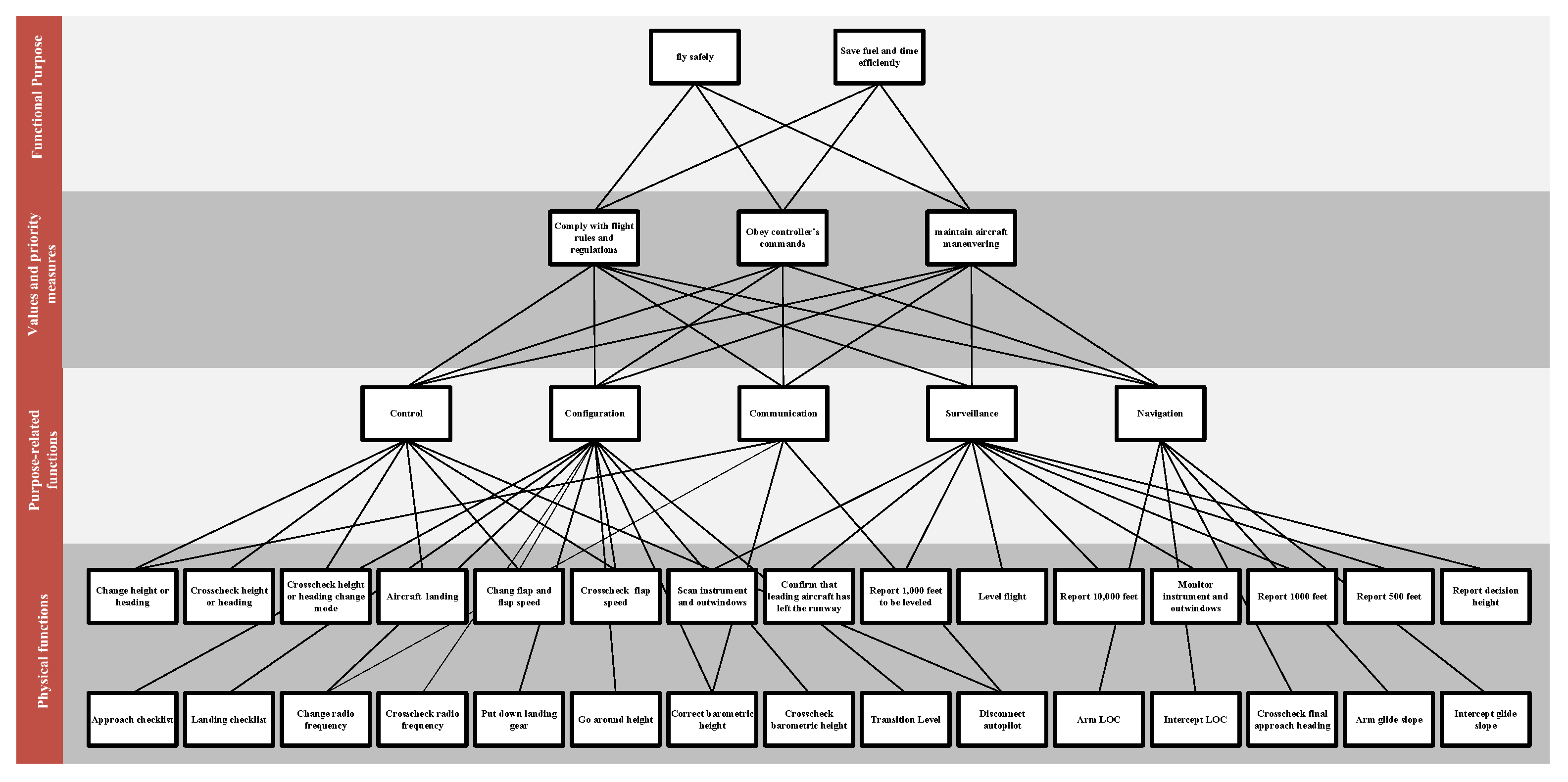
HCD is the performance-based approach that focuses on making the design available for human throughout the lifecycle of the system [29]. It features early and frequent user involvement, performance evaluation, and an iterative design-test-redesign process. The NASA Human Systems Integration Practitioner’s Guide provides a very clear and unambiguous definition of HCD, and a typical HCD process includes the following: concepts of operation and scenario development, task analyses, function allocation between humans and systems, allocation of roles and responsibilities among humans, iterative conceptual design and prototyping, human–system performance evaluation [30]. This paper applied the HCD approach to SPO and developed the study flow as shown in Figure 1. The four steps in the flowchart are described in detail in the subsequent subsections.
2.1. Develop the TCO Model
In this paper, the TCO model was developed through two steps of data collection and data analysis. The data collection combined two methods of direct observation and focus groups to collect the flight tasks in the current aviation system, and the collected data were analyzed using task analysis to develop the TCO model.
2.1.1. Data Collection
This study was supported by the international air passenger transport company in China. A total of 10 pilots (5 CAs and 5 FOs, all male) aging from 25 to 45 years (M = 33.5; SD = 7.21) participated in the study. The study was advertised with the use of posters and detailed information was emailed to interested participants through airline contacts. All pilots were aware of the purpose of the study and wrote a consent form prior to the observations. Audio and video recordings of five flights captured the routine work in the cockpit. Accident statistics show that a pilot is at most risk for an accident during the approach and landing than any other phase of a flight. Therefore, the approach and landing was selected as the case study scenario in this paper, which resulted in approximately 20 min of recordings. These recordings were transcribed into six categories of excel files as follows:
- Flight task of scenario;
- What information the pilot was listening to;
- What information the pilot was saying;
- Who the pilot was speaking to;
- What actions the pilot was undertaking;
- What equipment the pilot was observing.
Focus groups [31,32,33] were undertaken to provide additional supportive data for TCO model construction and analysis. The focus group session for this research was composed of 10 pilots participating in the above five flights. During the session, two pilots (1 CA and 1 FO) were asked to describe the start conditions, respective operations and operations logic of each flight task to the rest of the group by watching the video recording their flight, and the other participants in the group were encouraged to provide commentary. Questions about the scenario varied from the role of pilot(s), to what made the scenario challenging, and what would happen if the FO was absent. This session lasted for one day, with a two-hour break for lunch. The whole session was recorded for later analysis.
2.1.2. Data Analysis
Task analysis is characteristically used to systematically describe the process of human–system interaction for specifying the tasks of each agent (both operators and automation equipment) as well as the sequence and conditions for performing tasks [34,35]. Many types of task analysis techniques have been developed, including Cognitive Task Analysis (CTA) [36], which is used to identify key cognitive tasks when the operators interact with automation; Goal Directed Task Analysis (GDTA) [37], which is used to identify the tasks required by operators to achieve the goal and the situational awareness required to accomplish those tasks; and Goals, Operators, Methods and Selection (GOMS) [38], which is the human information processor model derived from the Human–Computer Interaction (HCI) and used specifically for the description of human performance. Hierarchical Task Analysis (HTA) [39] is an extension of the traditional task analysis. HTA has the following two advantages: (1) HTA has a strict hierarchical structure that decomposes the top-level goals of the system into the next-level sub-goals, and continues to decompose sub-goals up to indecomposable operations, providing a structured overview of the entire system operation; (2) HTA provides tasks, subtasks, operations and plans for achieving the goals, which detailly analyze and document the cognitive and physical processes related to the goal. Considering the above advantages, this paper uses HTA to analyze the collected data [40].
Depending on the location of the aircraft, the scenario was divided into four flight segments: transition segment, initial approach segment, intermediate approach segment and final approach segment. The four flight segments were used as reference points to determine the four overall goals. Each flight segment was broken down into multiple tasks by decomposing each overall goal into more specific task goals. The tasks were then decomposed into smaller, more specific operations. In addition, plans for how to achieve the goals were added while the goals were being decomposed. The developed TCO model has four layers: flight scenario layer, flight segment layer, flight task layer and pilot operations layer, as shown in Figure 2. The final TCO model was created with the aid of Microsoft Visio drawing, which was completed by two research team members and co-author Ding who has been a full-time commercial air transport pilot for 13 years at an international airline.
2.2. Validate the TCO Model
The study team members conducted a TCO interview session with two Subject Matter Experts (SMEs) with extensive experience in the aviation field (one current CA, one current FO), who were not involved in data collection. First through discussion between the researchers and SMEs, four questions were developed to determine if tasks and operations needed to be eliminated or added, and to identify possible improvements to the plans. The SMEs then reviewed the detailed tasks, operations, and plans of the draft TCO model that could represent the actual flight scenario and discussed with the researchers regarding the four key questions mentioned below:
- What tasks and operations are missing?
- What tasks and operations are unnecessary?
- How can the plans be improved?
- Using the descriptive tasks, operations and plans of the TCO model, how well could they instruct another pilot to fly?
Researchers recorded all discussions with the permission of the SMEs. Any modifications to the TCO model required rigorous review and discussion between the researchers and the SMEs. Based on above discussions and modifications, the TCO high-fidelity model of the current Area Navigation (RNAV) approach and landing scenario was developed and validated.
2.3. Extend to the SPO Model
Work Domain Analysis (WDA) is a common component of Cognitive Work Analysis (CWA) which is used to identify the purposes of system and the functions to achieve those purposes. WDA typically uses Abstraction Hierarchy (AH) to represent the purposes, constraints and functions of work domain [41,42]. The highest level is functional purposes, which describes the reason for the existence of the system, independent of time, and they exist as long as the system exist. The next level is values and priority measures, which more explicitly lists constraints on functional purposes and determines the extent to which the system achieves its functional purposes. The intermediate level is purpose-related functions, which specifies the functions that need to be performed to satisfy the functional purposes, and which are independent of any technical assumptions. The next level is called physical functions, which specifies the physical processes required to support purpose-related functions. The final level specifies the physical objects or forms that implement the physical functions. AH has been widely used in aviation. Stanton et al. [10] used AH to identify the functional constraints of current aviation systems which provided the basis for development of subsequent phases to explore various staffing options for future SPO flight cockpits. Huddlestone et al. [43] used AH to identify the functional requirements of SPO in the low-visibility taxi scenario as well as to identify changes resulting from the introduction of new technologies and agents. Additionally, Pritchett et al. [44] used AH to explore how functions were allocated among system agents under different cockpit automation technology assumptions.
Considering the powerful capabilities of AH to identify functional requirements and represent different function allocations, this paper adopted the combination of HTA and AH methods to extend to the future SPO model. The validated TCO model detailed the flight task, the pilot’s operations and cognitive decisions, and the ways in which the operations were executed during the current approach and landing scenario, and it could be used as the foundation for developing an AH model of the current system. The obtained AH model could identify the functional requirements for the transition to SPO, and these requirements in turn led to corresponding technical assumptions. Introducing technical assumptions into the current AH model implemented the reallocation of functions in the current aviation system to agents of the SPO conceptual framework, and function allocation results were used to guide the development of future SPO model. In order to ensure the verifiability and validity of the model, the SPO model was validated by the SMEs from the previous interview session. Before the start of the SPO interview session, the researcher introduced the SPO to the SMEs. The SMEs were briefed on the conceptual framework of SPO, expected aviation technology, and pilot task changes resulting from aviation technologies. A draft SPO model was subsequently reviewed and modifications were proposed accordingly. Using SMEs’ input, the SPO model was modified to be more representative of the SPO environment.
2.4. Evaluate the SPO Model
To achieve the optimal design of future system, quantitative data from SPO model evaluation need to be collected for iterative improvement. This iterative evaluation is also a fundamental principle of HCD, which helps to identify risks and problems early in the system lifecycle and reduced the development cost of the system [45]. Human-in-the-loop (HITL) simulation and Human Performance Modeling (HPM) are two common approaches for system evaluation. HITL can provide a better understanding of human capabilities and limitations by evaluating pilot interactions and responses with simulated equipment in real time [46], but this approach is typically time-consuming and expensive. However, HPM allows the use of computer to simulate system that has not yet been built [47], and model changes and data acquisition are more flexible and efficient. Network analysis as a method of HPM has been widely used for new system evaluation [48,49,50]. The researchers combined Social Organisation and Cooperation Analysis Contextual Template (SOCA-CAT) with Social Network Analysis (SNA) to evaluate different design candidates for SPO [10,51] and to explore the impact of pilot incapacitation on SPO [52]. Each grid in SOCA-CAT was transformed into actor-to-actor and actor-to-function connections, which were used to model actor-to-actor network and actor-to-function network to evaluate SPO system using network parameters [53]. However, the coarse granularity of the network constructed using SOCA-CAT ignores the way actors interact with the physical objects of the system and incorrectly increases the connections between actors. This paper used the models constructed by HTA to describe in detail the interactions between actors and the operations between actors and physical objects in the TCO and SPO systems, which were more representative of the actual flight scenarios, and transformed these into two richer network models for use in SNA.
SNA can provide network metrics to characterize the entire network and nodes [54]. These metrics are analyzed by comparing the TCO and SPO networks to evaluate the results of the function allocation. Network metrics are divided into two categories based on the level of analysis to be performed: network level and node level. Network level are measurements of the overall structure of the network and thus provide insights about the important properties of the network. The main parameters are shown below.
- Nodes: the number of entities in the network.
- Edges: the number of pairs of connected nodes.
- Interactions: all ties in the network.
- Density: the ratio of the number of edges in the network relative to the maximum possible number of edges in the network.
- Reciprocity: the ratio of the number of interconnections in the network to the number of all connections in the network.
- Diameter: the maximum eccentricity of all nodes in the network.
Node level explores the Centrality or Prestige measurement to understand the position of the nodes in the overall structure of the graph and therefore helps to identify the key actors in the network. Most Centrality indices are designed for undirected graphs, where the relations are non-directional. For digraphs, where the relations were directional, most centrality measures can also be calculated by focusing on outbound ties. However, Prestige indices are based on the inbound ties to each node from all others, so these indices can only be calculated on directed graphs. Since both networks in this paper are directed, the main parameters shown below are illustrated as directed graphs.
- Degree Centrality: the total number of ties starting from a node. Despite its simplicity, it is an effective means of assessing the importance and influence of an actor in the network.
- Influence Range Closeness Centrality: the standardized inverse average distance between a node and every other node reachable from it. This improved Closeness Centrality index is optimized for directed graphs which are not strongly connected. This index reflects on how close each node was to all other nodes in the network. Nodes with high Influence Range Closeness Centrality are those who could reach many other nodes quickly.
- Betweenness Centrality: the ratio of all geodesics between pairs of nodes which run through a node. It reflects how often that the node lay on the geodesics between the other nodes of the network. Assuming that communication in a network occurred along the geodesic, the high Betweenness Centrality score is considered to have a higher likelihood of being able to control information flow in the network.
- Eigenvector Centrality: the ith element of the leading eigenvector of the adjacency matrix. It is a more detailed version of the Degree Centrality index. This index assumes that not all ties have the same importance by taking into account not only the quantity, but especially the quality of these ties.
- Degree Prestige: the number of inbound ties at node. Nodes with higher Degree Prestige are considered more prominent among others because they receive more information.
- PageRank Prestige: an importance ranking for each node based on the structure of its incoming ties and the rank of the nodes linking to it.
- Proximity Prestige: measurements of how proximate a node is to the nodes in its influence domain—the influence domain of a node is the number of other nodes that can reach it. To put it simply, in Proximity Prestige what matters is how close are all the other nodes to the node.
3. Results and Discussions
3.1. TCO Model
The validated TCO model is provided in the Appendix A at the end of this paper. The following subsections summarize the flight tasks of four flight segments of approach and landing scenario. These are best read in conjunction with the full TCO model.
3.1.1. Transition Segment and Initial Approach Segment
As aircrafts get closer to the terminal area, all the aircrafts landing at the airport converge there and the traffic becomes more and more congested accordingly. In order to improve the traffic flow in the terminal area, Air Traffic Controller(ATC) needs to issue radar vector commands to flight crew to guide them to quickly transition to the intermediate approach segment, thus radar control replaces procedure control and improves the safety, orderliness and efficiency of air traffic control. This process includes transition segment and initial approach segment, which begins when the cockpit crew contacts the approach ATC (tasks 1.2, 1.3). The main goal of both segments is a faster transition to the intermediate approach segment, and the tasks performed to accomplish this goal are mainly receiving radar vectors (tasks 1.13, 1.14, 1.15, 2.1, 2.2, 2.7, 2.8, 2.9, 2.11, 2.12) and altitude change (tasks 1.4, 1.5, 1.16, 1.17, 2.3, 2.4, 2.7, 2.8, 2.9, 2.10) commands from the approach ATC. According to instrument flight rules, pilots need to keep scanning the Primary Flight Display (PFD), Navigation Display (ND) and outwindows (task 1.1), execute the transition level (tasks 1.6, 1.7) and approach checklist (task 1.8), and report 10,000 ft (task 1.9), 1000 ft to be leveled (tasks 1.10, 1.20, 2.5) and level flight (task 2.6). In addition, as the altitude decreases and the aircraft gets closer to the terminal area, the traffic density increases, requiring release of flaps (tasks 1.11, 1.12, 1.18, 1.19) to reduce the flight speed to maintain the interval.
3.1.2. Intermediate Approach Segment
The main goal of intermediate approach segment is to intercept the Localizer (LOC) and Glideslope (GS) signals to provide short-range guidance to aircraft to allow them to approach a runway at night or in bad weather. First, the PF arms the LOC (task 3.1), and the aircraft waits to receive the horizontal guidance signal. Since the aircraft is cleared to descend further before entering the intermediate approach segment to receive the subsequent GS signal, the PM scans the Flight Mode Annunciator (FMA) change on the PFD at the end of the aircraft’s descent and reports it to remind the PF that aircraft is currently in level flight (task 3.2). When the aircraft detects the LOC signal, the PM reminds the PF that the LOC diamond icon below the PFD is starting to move. Both pilots watch the diamond icon move to the center and the change in the FMA pattern, indicating that the LOC signal has been intercepted (task 3.3), while the value of the heading display window jumps to final approach heading (task 3.4). After intercepting the LOC, the next step is to arm the GS to receive the aircraft vertical guidance signal (task 3.5). During this period, PF scans that the aircraft is five nautical miles away from the runway threshold, and then commands the PM to put down the landing gear (task 3.6), which results in an increase in forward resistance and a decrease in speed to reach the conditions for further release of the flaps (tasks 3.7, 3.8). The aircraft continues to fly horizontally until it detects GS signals (task 3.9), which is the same as the process of intercepting the LOC signals. After the GS signals are intercepted, the aircraft is following the glide path of approximately 3° above horizontal (ground level) to remain above obstructions and reach the runway at the proper touchdown point.
3.1.3. Final Approach Segment
The main objective of final approach segment is to complete the pre-landing preparations and landing. The pre-landing preparations are the following. Firstly, the flight crew should set the go-around altitude (task 4.1) to deal with an aborted landing of an aircraft caused by unexpected situations, such as an unsterilized approach or an obstruction on the runway. Secondly, the flight crew has to set the landing flaps (tasks 4.2, 4.3) to complete the aircraft’s landing configuration. Subsequently, the approach ATC transfers the air control authority of the aircraft to the tower ATC. The flight crew switches radio frequencies (task 4.4, 4.5), reports the current aircraft situation to the tower ATC, receives the command to set the current airfield barometric altitude to make the aircraft’s landing more precise (task 4.6, 4.7), and waits for the tower ATC to issue a landing clearance. Finally, the flight crew executes the landing checklist and completes all preparations before landing (task 4.8). After the pilots have completed these preparations and received landing clearance from the tower ATC, the PF disengages the autopilot and begins preparing for landing (task 4.9). During the manual flight control of the aircraft, the flight crew keeps monitoring the speed and horizontal and vertical guidance on the PFD instrument, and situation of outwindows to determine whether the aircraft is approaching stably (task 4.10). In addition to the above information monitored, PM is also responsible for monitoring the aircraft altitude. When the aircraft reaches 1000 ft (task 4.12), 500 ft (task 4.13), and decision height (task 4.14), PM reminds PF of the aircraft’s current altitude, and PF decides whether the aircraft continues to approach according to the current aircraft situation. After deciding to land (task 4.15), the flight crew listens to automated voice height reminders and adjusts the aircraft in real time.
3.2. Work Domain Analysis
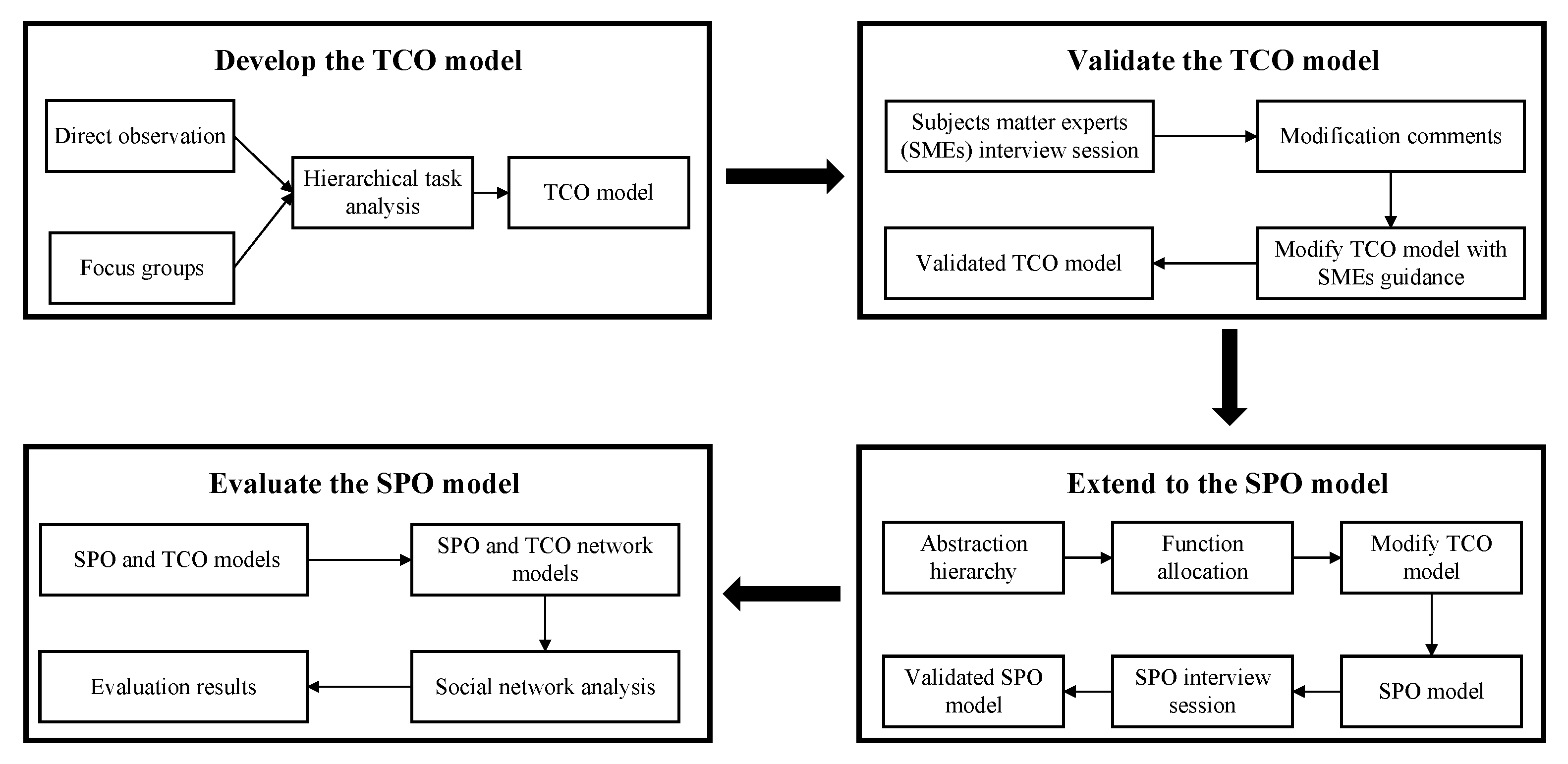
Traditional WDA uses the combination of top-down and bottom-up methods to model AH. The last level of AH is all the physical objects involved in the physical functions, ignoring the functions to be performed by the pilots in the system. In this paper, the top-down method was used to model the AH based on the developed TCO model, where the last level of the AH was the functions to be performed by the pilots in the system to achieve the physical functions of the upper level. This made it easier than the traditional WDA to understand the functions performed by the pilots and to identify the functional requirements after the conceptual framework has changed in the system. The AH modeled in this paper is shown in Figure 3, and due to the large number of functions to be performed by the pilots, the last level is represented in the form of the table, as shown in Table 1. In order to achieve SPO, the functions of the PM need to be reallocated to the agents in the conceptual framework of the SPO. The functions of the PM in the current approach and landing scenario can be obtained through the AH and are outlined as the following five function requirements.
- Check changes in the flight deck (including altitude, heading, speed and so on), which is critical to the safety of civil air transportation. To accomplish these functions, the PM and PF require a great deal of verbal interaction.
- Communicate with ATC to ensure that the cockpit receives accurate information from ATC.
- Remind the PF of the current situation of the aircraft as required by the instrument flight rules. If no reply is received from the PF twice, the PF is judged to be incapacitated.
- Monitor the cockpit instrument equipment as well as the external environment to respond to emergency situations encountered by the aircraft and to ensure flight safety. The main reason for this is the high traffic density and complex environment of the terminal area.
- Be responsible for system configuration functions in the cockpit including checklists, radio changes, flap settings and so on.
In the conceptual framework of the SPO, due to the higher workload and risk in the terminal area, more traffic restrictions, and the management of aircraft merging and separation, the Ground Operator (GO) will provide one-on-one assistance to the Onboard Single Pilot (OSP), acting as a remote co-pilot assists the OSP to safely fly the aircraft in the manner similar to current TCO. This also brings a new problem, namely the shift from co-located collaboration to distributed remote collaboration. In order to ensure the safe and efficient execution of this new collaboration, new automated tools must be introduced to act as the medium between air and ground pilots. Given the above analysis, this paper proposes the following function assumptions:
- The ground mirror system, a one-to-one replica of the operation interface of the air cockpit. It allows GO to monitor the instrument equipment and external environment of the flight deck and to control the aircraft by the ground mirror system.
- The air-ground collaboration automation in the cockpit, which accomplishes four main functions: send the cockpit change information to the ground station; receive change information from the ground station; remind the OSP of the changes made by the GO and the aircraft situation required to be reported by the instrument flight rules; recognize the confirmation words after the OSP receives the aircraft’s situational reminders.
- The air-ground collaboration automation in the ground station, which also accomplishes four main functions: send the ground station change information to the cockpit; receive change information from the cockpit; remind the GO of the changes made by the OSP and the aircraft situation required to be reported by the instrument flight rules; recognize the confirmation words after the GO receives the aircraft’s situational reminders.
- The communication link between the ground station and the cockpit, by which functions requiring extensive interaction between the OSP and GO will be completed.
- The communication link between the ground station and the Air Traffic Management (ATM), by which GO assists OSP to complete communication with ATC. In addition, the OSP can monitor the readback information from the GO.
- System configuration functions often require pilots to head down to complete them. Therefore, OSP will take on system configuration functions with shorter head down times, while GO will take on system configuration functions with longer head down times.
Since the transition from the current TCO to the future SPO changes the way pilots collaborate, the functional purpose, values and priority measures, purpose-related functions, and physical functions of the AH remain unchanged. In this paper, the functions in the current aviation system (see Table 1) are reallocated to the various agents of SPO by combining the conceptual framework of SPO and the six functional assumptions mentioned above, and the results are shown in Table 2, where Flight Deck Automation (FDA) represents the functions to be performed by the newly added automation in the cockpit and Ground Automation (GA) represents the functions to be performed by the ground station automation. The results of the function allocation in Table 2 are fed back to the pilot operations layer of the TCO model, and the modified model represents the approach and landing flight scenario of future SPO.
3.3. SPO Model
The developed SPO model was reviewed by SMEs and then modified according to their comments to complete the validation of the model. The validated SPO task model is provided in the Appendix B. The entire SPO model is described in detail below in conjunction with Appendix B. Monitoring the instrument equipment and outwindows (tasks 1.1, 4.10) will be performed by both the OSP and the GO, which is the same as the current TCO to identify and resolve problems in the system and external environment in a timely manner to ensure flight safety. To ensure that the OSP and GO are aware of the aircraft’s situation at critical moments during the monitoring process, the air-ground collaboration automation will send verbal reminders (tasks 1.9, 1.10, 2.6, 3.1, 3.3, 3.4, 3.5, 3.9, etc.) to the pilots in accordance with the instrument flight rules. After hearing the situational reminders, both pilots reply "Copy". The air-ground collaboration automation then recognizes the verbal information of both pilots to confirm that they have received situational reminders, which can also be used as a means of detecting pilot incapacitation. Setting altitude and heading correctly (tasks 1.4, 1.5, 1.13, 1.14, 2.9, 4.6, etc.) is critical to flight safety. In these tasks GO is responsible for communicating with ATC to ensure that the information issued by ATC is received correctly, and OSP is responsible for changing altitude and heading and selecting altitude and heading modes. After completing these tasks, the air-ground collaboration automation will remind the GO to check if this information has been changed and selected correctly (tasks 1.5, 1.14, 1.15, 2.12, etc.). Finally, the OSP will take on some of the PM’s head-down tasks (such as set flaps, put down landing gear, etc.). These head-down tasks are usually shorter (tasks 1.11, 3.6, etc.), while for longer head-down tasks (e.g., radio changes), the GO will assist the OSP with manual operations, and OSP check and perform them (tasks 1.2, 1.8, etc.).
3.4. Social Network Analysis
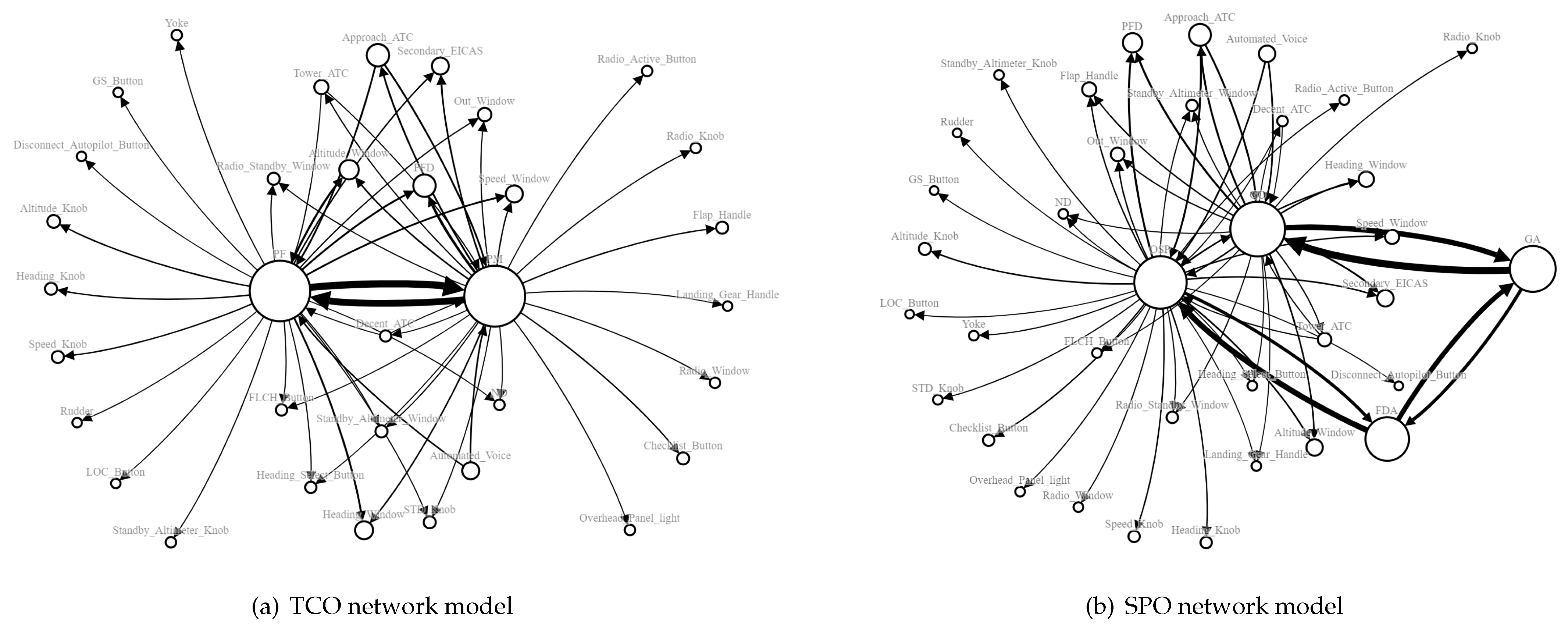
The developed TCO model and SPO model describe the relations (including interactions between actors, operations performed by actors on objects, and feed back from objects to actors) between various agents (actors and objects related to operations) in the current and future aviation systems, respectively, and these agents and relations can be transformed into nodes and edges in the network to develop two weighted directed network models as shown in Figure 4, where the weights represent the frequency of connections. This paper used the open-source software the Social Network Visualizer (SocNetV) Version 3.0.4 to measure network-level and node-level parameters of the two networks separately to evaluate the impact of the transition from the current TCO to the future SPO. The network-level metrics are shown in Table 3. The first three indexes, Nodes, Edges and Interactions, are an overall description of the network. Since SPO adds two automation agents (Nodes = 36, Nodes = 34), the number of edges and interactions between nodes increases accordingly (Edges = 60, Edges = 53; Interactions = 369, Interactions = 297). The last three indexes are obtained based on the first three indexes, and the density and reciprocity indexes of SPO are higher than those of TCO (Density = 0.0476, Density = 0.0472; Reciprocity = 0.13, Reciprocity = 0.08), indicating that the SPO network is more resilient than TCO, and the SPO system is more stable and can cope with more emergencies, further also indicating that the system performance of SPO is better than that of TCO.
In addition to system performance, it is necessary to compare the human performance of OSP vs. PF and GO vs. PM, and node-level metrics as shown in Table 4 can be used for such evaluations. Table 4 also contains metrics of the two automation agents added to the SPO to analyze their roles in the SPO system. The Degree centrality index describes the number of ties issued by the node, representing pilots performing action and communication operations. This index of OSP and GO in SPO is significantly lower than that of PF and PM in TCO (Degree centrality = 99, Degree centrality = 133; Degree centrality = 100, Degree centrality = 130). The Degree prestige index describes the amount of information received by the node, representing pilots performing visual and auditory operations. This index of OSP and GO is also lower than that of PF and PM (Degree prestige = 59, Degree prestige = 69; Degree prestige = 69, Degree prestige = 73). These two indexes show that the workload of pilots in SPO is greatly reduced, mainly by delegating a large number of interactions between PF and PM to air-ground collaboration automation (Degree centrality = 68, Degree centrality = 68; Degree prestige = 37, Degree prestige = 66). As the second pilot is moved to the ground, some of his or her operations in the cockpit are assigned to the OSP. This results in that the Eigenvector centrality index of OSP is higher than that of PF (Eigenvector centrality = 0.172; Eigenvector centrality = 0.011), and GO is lower than PM (Eigenvector centrality = 0.646; Eigenvector centrality = 0.688). Although the automations replace the pilots to complete some of the operations, their Eigenvector centrality indexes are much smaller compared to the pilot agents (Eigenvector centrality = 0.004; Eigenvector centrality = 0.011). This also means that automations only replace some of the simple operations, and the OSP is still responsible for operations that are critical to flight safety. The Influence range closeness centrality index of OSP and GO is lower than that of PF and PM (Influence range closeness centrality = 1.843, Influence range closeness centrality = 2.033; Influence range closeness centrality = 1.696, Influence range closeness centrality = 2.026), indicating that OSP and GO are slower in acquiring each other’s situation than the current TCO. This is mainly due to the fact that the two pilots in SPO are not co-located and need to be linked by the air-ground collaboration automation (Influence range closeness centrality = 1.774, Influence range closeness centrality = 1.84). The Betweenness centrality index of the OSP is the highest of all nodes in Table 4 (Betweenness centrality = 168). This is mainly because the OSP is responsible for all information change authorities in the cockpit, including checking and executing manual operations assisted by the GO, which makes the OBP the hub between the flight deck and the ground station. The PageRank prestige index of OSP and GO is higher than that of PF and PM (PageRank prestige = 0.016, PageRank prestige = 0.013; PageRank prestige = 0.016, PageRank prestige = 0.013). In addition, the Proximity prestige index of OSP and GO is higher than that of PF and PM (Proximity prestige = 0.667, Proximity prestige = 0.418; Proximity prestige = 0.71, Proximity prestige = 0.419). Due to the lack of body language information of the two pilots in the SPO, the air ground collaboration automations need to send more reminders to supplement the lack of this part of the information, which also causes their two indexes to be larger (PageRank prestige = 0.008, PageRank prestige = 0.008; Proximity prestige = 0.635, Proximity prestige = 0.681).
Analyzing the above network metrics, the SPO developed in this paper has the advantages of better stability, less pilot workload and higher safety than the current TCO. However, these network metrics also reflect a number of safety hazards in SPO. Since the OSP is the connection point between the flight deck and the ground station, it is critical to the safety of the SPO. If the OSP is incapacitated, it may cause a great loss to the safety of the system. It is necessary to take measures to detect the OSP incapacitation early.
4. Conclusions
In this paper, the human-centered design approach was used to develop and evaluate SPO to identify design flaws of the system at an early stage. Firstly, the researchers used direct observation and focus groups to obtain data from the current TCO and processed these data with HTA to model the TCO. Secondly, the developed TCO model was submitted to the SMEs for review, and the researchers modified the model based on the comments given by the SMEs to complete the validation of the TCO model. Subsequently, the researchers proposed function requirements and function assumptions for the transition from the current TCO to the future SPO by combining the HTA and AH to complete the system function reallocation, and fed back the results of function allocation into the TCO model to develop the SPO model, which was also reviewed and validated by the SMEs. Finally, the researchers transformed the TCO model and SPO model into two network models and used SNA to evaluate the results of function allocation from network-level and node-level metrics.
In the entire SPO development and evaluation process, the TCO model developed with HTA detailed the operation process of the current TCO system in the approach and landing scenario, so that it could be used as input to the WDA to model the AH using the top-down method. On the other hand, AH could complete the reallocation of system functions and fed back the function allocation results to the TCO model to develop the SPO model. These two approaches complemented and input each other. AH was an overview of HTA, and HTA was a specific representation of AH. This also provided a structured approach for the transition from the current TCO to the future SPO. In addition, the pilot operations layer of the TCO and SPO models detailed the interactions between actors and between actors and physical objects, which can be transformed into two network models to be used as input to the SNA evaluation method. This evaluation method could quickly identify the advantages and problems of future SPO compared to current TCO, but the evaluation of the workload was too simplified and did not consider the pilots’ cognitive load. In the future, human-in-the-loop or agent-based cognitive modeling can be used to remedy this deficiency.
Current SPO research focuses on the design and evaluation of operational concepts, the development of new technologies, and methods of function allocation. Evaluating the impact of introducing SPO into current aviation systems simply uses idealized models that do not represent actual flight situations. This paper selected the current approach and landing flight scenario as the research object to explore more practical problems. Compared with previous work, this paper has the following contributions:
- (1)
- Developed a complete human-centered design process, including data collection, system design, and system evaluation, that can be applied to other flight phases.
- (2)
- Systematically proposed five functional requirements and six functional assumptions for the transition from current approach and landing scenarios to future SPO to guide the design of cockpit automation and the development of ground station.
- (3)
- Developed two detailed models of TCO and SPO that can be used to guide the development of HITL simulations and as input to other HPM.
The results of the evaluation suggested that incapacitation of OSP will be a major challenge for achieving SPO in the future. In order to explore the specific impact of pilot incapacitation on SPO, the human-centered study flow designed in this paper can be applied to pilot incapacitation scenario.
Author Contributions
Conceptualization, M.L.; methodology, M.L.; software, M.L.; validation, D.D.; formal analysis, M.L.; investigation, M.L.; resources, D.D.; data curation, M.L.; writing—original draft preparation, M.L.; writing—review and editing, M.W. and G.W.; supervision, M.W. and G.W.; project administration, M.W.; funding acquisition, M.W. All authors have read and agreed to the published version of the manuscript.
Funding
This research was funded by Natural Science Foundation of Shanghai (20ZR1427800), and New Young Teachers Launch Program of Shanghai Jiao Tong University (20X100040036).
Institutional Review Board Statement
Not applicable.
Informed Consent Statement
Informed consent was obtained from all subjects involved in the study.
Data Availability Statement
Not applicable.
Acknowledgments
The authors would like to thank the two subject matter experts with extensive experience in the aviation field for their invaluable assistance.
Conflicts of Interest
The authors declare no conflict of interest.
Abbreviations
| AH | Abstraction Hierarchy |
| ATC | Air Traffic Controller |
| CA | Captain |
| CTA | Cognitive Task Analysis |
| CWA | Cognitive Work Analysis |
| GA | Ground Automation |
| GS | Glideslope |
| FMA | Flight Mode Annunciator |
| FO | First Officer |
| GDTA | Goal Directed Task Analysis |
| GO | Ground Operator |
| HCD | Human-centered Design |
| HITL | Human-in-the-loop |
| HPM | Human Performance Modeling |
| HTA | Hierarchical Task Analysis |
| LOC | Localizer |
| NASA | National Aeronautics and Space Administration |
| ND | Navigation Display |
| OSP | On-board Single Pilot |
| PF | Pilot Flying |
| PFD | Primary Flight Display |
| PM | Pilot Monitoring |
| PNF | Pilot Not Flying |
| RNAV | Area Navigation |
| RPKs | Revenue Passenger Kilometers |
| SMEs | Subject Matter Experts |
| SNA | Social Network Analysis |
| SOCA-CAT | Social Organisation and Cooperation Analysis Contextual Template |
| SPO | Single Pilot Operations |
| TCO | Two-crew Operations |
| UBS | Union Bank of Switzerland |
| WDA | Work Domain Analysis |
Appendix A. Two-Crew Operations Model


Appendix B. Single Pilot Operations Model


References
- Maier, M.W. Architecting principles for systems-of-systems. Syst. Eng. 1998, 1, 267–284. [Google Scholar] [CrossRef]
- Bohn, R.E. How flying got smarter. In Proceedings of the 2010 IEEE Intelligent Vehicles Symposium, La Jolla, CA, USA, 21–24 June 2010; pp. 682–687. [Google Scholar]
- McLucas, J.L.; Leaf, H.W. Report of the President’s Task Force on Aircraft Crew Complement; Technical Report; President’s Task Force on Aircraft Crew Complement: Washington, DC, USA, 1981. [Google Scholar]
- FAA. NextGen Annual Report; Technical Report; Federal Aviation Administration: Washington, DC, USA, 2020.
- Deutsch, S.; Pew, R.W. Single Pilot Commercial Aircraft Operation; BBN Report; BBN Technologies: Cambridge, MA, USA, 2005. [Google Scholar]
- Harris, D. A human-centred design agenda for the development of single crew operated commercial aircraft. Aircr. Eng. Aerosp. Technol. 2007, 79, 518–526. [Google Scholar] [CrossRef]
- Belobaba, P.; Odoni, A.; Barnhart, C. The Global Airline Industry; John Wiley & Sons: Hoboken, NJ, USA, 2015. [Google Scholar]
- Cento, A. The Airline Industry: Challenges in the 21st Century; Springer Science & Business Media: Berlin, Germany, 2008. [Google Scholar]
- Vu, K.P.L.; Lachter, J.; Battiste, V.; Strybel, T.Z. Single pilot operations in domestic commercial aviation. Hum. Factors 2018, 60, 755–762. [Google Scholar] [CrossRef] [PubMed]
- Stanton, N.A.; Harris, D.; Starr, A. The future flight deck: Modelling dual, single and distributed crewing options. Appl. Ergon. 2016, 53, 331–342. [Google Scholar] [CrossRef] [PubMed]
- IATA. Air Passenger Monthly Market Analysis; Technical Report; International Air Transport Association: Montreal, QC, Canada, 2016. [Google Scholar]
- Deloitte. Global Aerospace and Defense Sector Outlook; Technical Report; Deloitte Touche Tohmatsu Limited: London, UK, 2019. [Google Scholar]
- Boeing. Pilot and Technical Outlook; Technical Report; Boeing Commercial Airplanes: Seattle, WA, USA, 2020. [Google Scholar]
- Castle, J.; Fornaro, C.G.D. Flying Solo—How Far Are We Down the Path Towards Pilotless Planes; Technical Report; UBS Global Research: Zurich, Switzerland, 2017. [Google Scholar]
- Comerford, D.; Brandt, S.L.; Lachter, J.B.; Wu, S.C.; Mogford, R.H.; Battiste, V.; Johnson, W.W. NASA’s Single-Pilot Operations Technical Interchange Meeting: Proceedings and Findings; Technical Report; National Aeronautics and Space Administration: Washington, DC, USA, 2013.
- Doyle, A. Embraer Reveals Vision for Single-Pilot Airliners; Technical Report; Embraer S.A.: São José dos Campos, Brazilian, 2010. [Google Scholar]
- ICAO. Rules of the Air; Technical Report; International Civil Aviation Organization: Montreal, QC, Canada, 2011. [Google Scholar]
- Skybrary. Pilot Flying (PF) and Pilot Monitoring (PM). Available online: https://www.skybrary.aero/articles/pilot-flying-pf-and-pilot-monitoring-pm (accessed on 23 August 2022).
- Neis, S.M.; Klingauf, U.; Schiefele, J. Classification and review of conceptual frameworks for commercial single pilot operations. In Proceedings of the 2018 IEEE/AIAA 37th Digital Avionics Systems Conference (DASC), London, UK, 23–27 September 2018; pp. 1–8. [Google Scholar]
- Schutte, P.C.; Goodrich, K.H.; Cox, D.E.; Jackson, B.; Palmer, M.T.; Pope, A.T.; Schlecht, R.W.; Tedjojuwono, K.K.; Trujillo, A.C.; Williams, R.A.; et al. The Naturalistic Flight Deck System: An Integrated System Concept for Improved Single-Pilot Operations; Technical Report; National Aeronautics and Space Administration, Ames Research Center: Moffett Field, CA, USA, 2007.
- Liu, J.; Gardi, A.; Ramasamy, S.; Lim, Y.; Sabatini, R. Cognitive pilot-aircraft interface for single-pilot operations. Knowl.-Based Syst. 2016, 112, 37–53. [Google Scholar] [CrossRef]
- Johnson, W.; Lachter, J.; Feary, M.; Comerford, D.; Battiste, V.; Mogford, R. Task allocation for single pilot operations: A role for the ground. In Proceedings of the HCI Aero 2012-International Conference on Human-Computer Interaction in Aerospace, Brussels, Belgium, 12 September 2012. Number ARC-E-DAA-TN5555. [Google Scholar]
- Bilimoria, K.D.; Johnson, W.W.; Schutte, P.C. Conceptual framework for single pilot operations. In Proceedings of the International Conference on Human-Computer Interaction in Aerospace, Santa Clara, CA, USA, 30 July–1 August 2014; pp. 1–8. [Google Scholar]
- Matessa, M.; Strybel, T.; Vu, K.; Battiste, V.; Schnell, T. Concept of Operations for RCO/SPO; Technical Report; National Aeronautics and Space Administration, Ames Research Center: Moffett Field, CA, USA, 2017.
- Boy, G.A. Human systems integration and design. In Handbook of Human Factors and Ergonomics; John Wiley & Sons: Hoboken, NJ, USA, 2021. [Google Scholar]
- Foyle, D.C.; Hooey, B.L. Human Performance Modeling in Aviation; CRC Press: Boca Raton, FL, USA, 2007. [Google Scholar]
- Gore, B.F.; Hooey, B.L.; Mahlstedt, E.; Foyle, D.C. Evaluating NextGen Closely Spaced Parallel Operations Concepts with Validated Human Performance Models: Scenario Development and Results; Technical Report; National Aeronautics and Space Administration: Washington, DC, USA, 2013.
- Hooey, B.L.; Foyle, D.C.; Andre, A.D. A human-centered methodology for the design, evaluation, and integration of cockpit displays. In Proceedings of the NATO RTO SCI and SET Symposium on Enhanced and Synthetic Vision Systems, Ottawa, ON, Canada, 10–12 September 2002. [Google Scholar]
- ISO. Human Centred Design Processes for Interactive Systems; Technical Report; International Organization for Standardization: Geneva, Switzerland, 2010. [Google Scholar]
- Zumbado, J.R. Human Systems Integration (HSI) Practitioner’s Guide; Technical Report; National Aeronautics and Space Administration: Washington, DC, USA, 2015.
- Billson, J.M. Focus groups: A practical guide for applied research. Clin. Sociol. Rev. 1989, 7, 24. [Google Scholar]
- Byers, P.Y.; Wilcox, J.R. Focus groups: A qualitative opportunity for researchers. J. Bus. Commun. (1973) 1991, 28, 63–78. [Google Scholar] [CrossRef]
- Ng, S.L.; Baker, L.; Cristancho, S.; Kennedy, T.J.; Lingard, L. Qualitative research in medical education: Methodologies and methods. In Understanding Medical Education: Evidence, Theory, and Practice; John Wiley & Sons, Ltd.: Hoboken, NJ, USA, 2018; chapter 29; pp. 427–441. [Google Scholar]
- Kirwan, B.; Ainsworth, L.K. A Guide to Task Analysis: The Task Analysis Working Group; CRC Press: Boca Raton, FL, USA, 1992. [Google Scholar]
- Gore, B.F.; Wolter, C. A task analytic process to define future concepts in aviation. In Proceedings of the International Conference on Digital Human Modeling and Applications in Health, Safety, Ergonomics and Risk Management, Crete, Greece, 22–27 June 2014; pp. 236–246. [Google Scholar]
- Crandall, B.; Klein, G.; Klein, G.A.; Hoffman, R.R.; Hoffman, R.R. Working Minds: A Practitioner’s Guide to Cognitive Task Analysis; MIT Press: Cambridge, MA, USA, 2006. [Google Scholar]
- Endsley, M.R.; Bolte, B.; Jones, D.G. Designing for Situation Awareness: An Approach to User-Centered Design; CRC Press: Boca Raton, FL, USA, 2003. [Google Scholar]
- Card, S.K.; Moran, T.P.; Newell, A. The Psychology of Human-Computer Interaction; CRC Press: Boca Raton, FL, USA, 2018. [Google Scholar]
- Annett, J. Hierarchical task analysis (HTA). In Handbook of Human Factors and Ergonomics Methods; CRC Press: Boca Raton, FL, USA, 2004; pp. 355–363. [Google Scholar]
- Stanton, N.A. Hierarchical task analysis: Developments, applications, and extensions. Appl. Ergon. 2006, 37, 55–79. [Google Scholar] [CrossRef] [PubMed] [Green Version]
- Bisantz, A.; Burns, C. Applications of Cognitive Work Analysis, 1st ed.; CRC Press: Boca Raton, FL, USA, 2008. [Google Scholar]
- Naikar, N. Work Domain Analysis Concepts, Guidelines, and Cases, 1st ed.; CRC Press: Boca Raton, FL, USA, 2013. [Google Scholar]
- Huddlestone, J.; Sears, R.; Harris, D. The use of operational event sequence diagrams and work domain analysis techniques for the specification of the crewing configuration of a single-pilot commercial aircraft. Cognit. Technol. Work 2017, 19, 289–302. [Google Scholar] [CrossRef]
- Pritchett, A.R.; Kim, S.Y.; Feigh, K.M. Modeling Human–Automation Function Allocation. J. Cognit. Eng. Decis. Mak. 2014, 8, 33–51. [Google Scholar] [CrossRef] [Green Version]
- Boyer, J. Human Integration Design Processes (HIDP); Technical Report; National Aeronautics and Space Administration: Washington, DC, USA, 2014.
- Harvey, C.; Mullan, A.S.; Magyarits, S. Appendix 2: Best Practices in Development of Simulation Scenarios for Validation Activities in Fast and Real-Time Simulation; Technical Report; FAA and Eurocontrol: Washington, DC, USA, 2003. [Google Scholar]
- Wickens, C.; Sebok, A.; Keller, J. Modeling and Evaluating Pilot Performance in NextGen: Review of and Recommendations Regarding Pilot Modeling Efforts, Architectures, and Validation Studies; Technical Report; National Aeronautics and Space Administration: Washington, DC, USA, 2013.
- Baber, C.; Stanton, N.; Atkinson, J.; McMaster, R.; Houghton, R. Using social network analysis and agent-based modelling to explore information flow using common operational pictures for maritime search and rescue operations. Ergonomics 2013, 56, 889–905. [Google Scholar] [CrossRef] [PubMed]
- Cvitanovic, C.; Cunningham, R.; Dowd, A.M.; Howden, S.; van Putten, E. Using Social Network Analysis to Monitor and Assess the Effectiveness of Knowledge Brokers at Connecting Scientists and Decision-Makers: An Australian case study. Environ. Policy Gov. 2017, 27, 256–269. [Google Scholar] [CrossRef]
- Stewart, R.; Stanton, N.; Harris, D. Distributed situation awareness in an Airborne Warning and Control System: Application of novel ergonomics methodology. Cognit. Technol. Work 2008, 10, 221–229. [Google Scholar] [CrossRef]
- Stanton, N.A.; Harris, D.; Starr, A. Modelling and Analysis of Single Pilot Operations in Commercial Aviation. In Proceedings of the International Conference on Human-Computer Interaction in Aerospace, HCI-Aero’14, Santa Clara, CA, USA, 30 July–1 August 2014; Association for Computing Machinery: New York, NY, USA, 2014. [Google Scholar]
- Schmid, D.; Korn, B.; Stanton, N.A. Evaluating the reduced flight deck crew concept using cognitive work analysis and social network analysis: Comparing normal and data-link outage scenarios. Cognit. Technol. Work 2020, 22, 109–124. [Google Scholar] [CrossRef] [Green Version]
- Houghton, R.J.; Baber, C.; Stanton, N.A.; Jenkins, D.P.; Revell, K. Combining network analysis with Cognitive Work Analysis: Insights into social organisational and cooperation analysis. Ergonomics 2015, 58, 434–449. [Google Scholar] [CrossRef] [PubMed]
- Wasserman, S.; Faust, K. Social Network Analysis: Methods and Applications; Cambridge University Press: Cambridge, UK, 1994. [Google Scholar]
Figure 1.
The logic flow chart of the single pilot operations study.

Figure 2.
Layers of the current two-crew operations model.
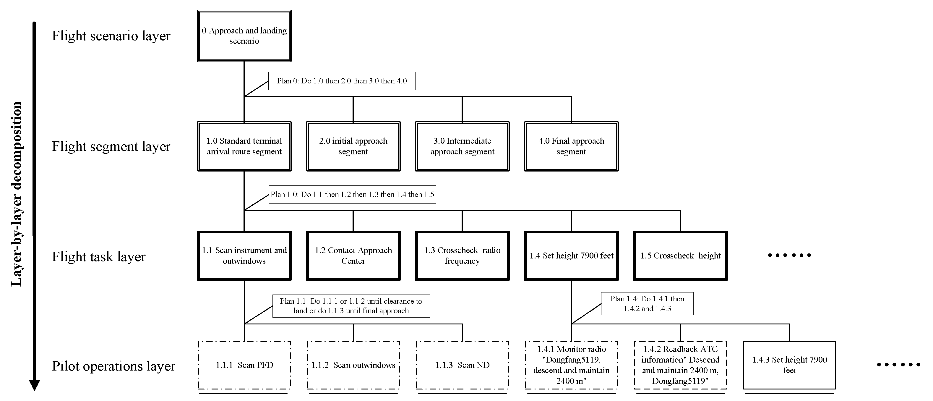
Figure 3.
A detail of the abstraction hierarchy of current two-crew operations.

Figure 4.
Two weighted directed network models transformed from TCO and SPO models.

Table 1.
Functions performed by the Pilot Flying (PF) and Pilot Monitoring (PM) in the current two-crew operations.
Table 1.
Functions performed by the Pilot Flying (PF) and Pilot Monitoring (PM) in the current two-crew operations.
| Physical Function | Pilot Flying (PF) | Pilot Monitoring (PM) |
|---|---|---|
| Change height or heading | Monitor radio information | Monitor radio information |
| Set height or heading on the MCP | Readback ATC information | |
| Crosscheck height or heading change mode | Point to the height or heading select mode button | Check height or heading display window |
| Say height or heading values to PM | Listen to height or heading values from PF | |
| Listen to confirmation from PM | Say confirmation to PF | |
| Aircraft landing | Listen to automated voice announcements | Listen to automated voice announcements |
| Adjust pitch up 2° to 3° to reduce rate of descent | ||
| Monitor all the way down the runway | ||
| Chang flap and flap speed | Remind PM to set flap | Listen to flap reminder from PF |
| Listen to check speed from PM | Say check speed to PF | |
| Glance at PM’s set flap action | Check the speed information on PFD | |
| Check the flap information on EICAS | Set flap | |
| Check the flap speed on PFD | Check the flap information on EICAS | |
| Set flap speed | Check the flap speed on PFD | |
| Crosscheck flap speed | Point to the speed display window | Check the speed display window |
| Say speed values to PM | Listen to speed values from PF | |
| Listen to confirmation from PM | Say confirmation to PF | |
| Scan instrument and outwindows | Scan PFD | Scan PFD |
| Scan ND | Scan ND | |
| Scan outwindows | Scan outwindows | |
| Confirm that leading aircraft has left the runway | Remind PM that Leading aircraft has left the runway | Listen to reminder from PF |
| Listen to confirmation from PM | Check whether the leading aircraft on the runway has left | |
| Say confirmation to PF | ||
| Aircraft landing | Remind PM that Leading aircraft has left the runway | Listen to reminder from PF |
| Listen to confirmation from PM | Check whether the leading aircraft on the runway has left | |
| Say confirmation to PF | ||
| Report 1000 ft to be leveled | Listen to reminder from PM | Remind PF that the aircraft is still 1000 ft from the target height |
| Say copy to PM | Listen to copy from PF | |
| Level flight | Listen to reminder from PM | Remind PF that the aircraft is flying level |
| Say copy to PM | Listen to copy from PF | |
| Report 10,000 ft | Listen to 10,000 ft reminder from PM | Remind PF about 10,000 ft |
| Say turning on lights to PM | Listen to turning on lights from PF | |
| Press the light switch on the overhead panel | ||
| Monitor instrument and outwindows | Monitor PFD | Monitor PFD |
| Monitor outwindows | Monitor outwindows | |
| Report 1000 ft | Listen to 1000 ft reminder from PM | Remind PF about 1000 ft |
| Remind PM that the aircraft continues approach | Listen to reminder from PF | |
| Say turning on taxi lights to PM | Listen to turning on taxi lights from PF | |
| Press taxi light switch on the overhead panel | ||
| Report 500 ft | Listen to 500 ft reminder from PM | Remind PF about 500 ft |
| Remind PM that the aircraft continues approach | Listen to reminder from PF | |
| Report decision height | Listen to approaching decision heigh reminder from PM | Remind PF about approaching decision heigh |
| Remind PM that the aircraft continues approach | Listen to reminder from PF | |
| Listen to decision heigh reminder from PM | Remind PF about decision heigh | |
| Remind PM that the aircraft continues approach | Listen to reminder from PF | |
| Approach checklist | Remind PM about approach checklist | Listen to approach checklist reminder from PF |
| Listen to height mode conversion and approach checklist completion from PM | Press checklist button | |
| Say copy to PM | Check lower EICAS | |
| Say height mode conversion and approach checklist completion to PF | ||
| Listen to copy from PF | ||
| Press checklist button | ||
| Landing checklist | Remind PM about landing checklist | Listen to landing checklist reminder from PF |
| Listen to go around height from PM | Press checklist button | |
| Point to the height display window | Check Lower EICAS | |
| Say go around height values to PM | Say go around height to PF | |
| Listen to confirmation from PM | Check height display window | |
| Listen to landing approach checklist completion from PM | Listen to go around height values from PF | |
| Say copy to PM | Say confirmation to PF | |
| Say landing approach checklist completion to PF | ||
| Listen to copy from PF | ||
| Press checklist button | ||
| Change radio frequency | Monitor radio information | Monitor radio information |
| Readback ATC information | ||
| Set radio frequency on the pedestal | ||
| Crosscheck radio frequency | Listen to confirmation of radio frequency from PM | Say confirmation of radio frequency to PF |
| Check radio frequency display windows | Listen to confirmation from PF | |
| Say confirmation of radio frequency to PM | Press radio active button | |
| Put down landing gear | Remind PM that put down landing gear | Listen to reminder from PF |
| Listen to copy from PM | Say copy to PF | |
| Glance at PM’s set landing gear action | Set the landing gear handle | |
| Check the landing gear information on the EICAS | Check the landing gear information on the EICAS | |
| Go around height | Set go around height | Glance at PF’s set go around height action |
| Point to the height display window | Check height display window | |
| Say go around height values to PM | Listen to go around height values from PF | |
| Listen to confirmation from PM | Say confirmation to PF | |
| Correct barometric height | Listen to report from PM | Report current situation to ATC |
| Monitor radio information | Monitor radio information | |
| Set the barometric height on the EFIS | Readback ATC information | |
| Set the standby barometric height | Set the barometric height on the EFIS | |
| Crosscheck barometric height | Say barometric height adjusted to PM | Listen to barometric height adjusted from PF |
| Listen to confirmation from PM | Check three barometric heights | |
| Say confirmation to PF | ||
| Transition Level | Listen to transition level reminder from PM | Remind PF about transition level |
| Press the barometric height knob | Press the barometric height knob | |
| Press the standby barometric height knob | ||
| Disconnect autopilot | Monitor radio information | Monitor radio information |
| Listen to readback from PM | Readback ATC information | |
| Remind PM about autopilot disconnection | Listen to autopilot disconnection reminder from PF | |
| Listen to copy from PM | Say copy to PF | |
| Press disconnect autopilot button | ||
| Adjust aircraft as necessary | ||
| Arm LOC | Remind PM that aircraft can intercept localizer | Listen to reminder from PF |
| Check ILS identification code | Check ILS identification code | |
| Remind PM about ILS identification | Listen to ILS identification reminder from PF | |
| Listen to right ILS identification from PM | Say right ILS identification to PF | |
| Remind PM about LOC | Listen to LOC reminder from PF | |
| Listen to copy from PM | Say copy to PF | |
| Press LOC button | ||
| Intercept LOC | Listen to LOC movement reminder from PM | Remind PF about LOC movement |
| Say copy to PM | Listen to copy from PF | |
| Listen to LOC interception reminder from PM | Remind PF about LOC interception | |
| Say copy to PM | Listen to copy from PF | |
| Crosscheck final approach heading | Check the heading display window | Check the heading display window |
| Say final approach heading value to PM | Listen to final approach heading value from PF | |
| Listen to confirmation from PM | Say confirmation to PF | |
| Arm glide slope | Remind PM about glide slope | Listen to glide slope reminder from PF |
| Listen to copy from PM | Say copy to PF | |
| Press glide slope button | ||
| Intercept glide slope | Listen to glide slope movement reminder from PM | Remind PF about glide slope movement |
| Say copy to PM | Listen to copy from PF | |
| Listen to glide slope interception reminder from PM | Remind PF about glide slope interception | |
| Say copy to PM | Listen to copy from PF |
Table 2.
Functions performed by the Onboard Single Pilot (OSP), Flight Deck Automation (FDA), Ground Operator (GO) and Ground Automation (GA) in the single pilot operations.
Table 2.
Functions performed by the Onboard Single Pilot (OSP), Flight Deck Automation (FDA), Ground Operator (GO) and Ground Automation (GA) in the single pilot operations.
| Physical Function | Onboard Single Pilot (OSP) | Flight Deck Automation (FDA) | Ground Operator (GO) | Ground Automation (GA) |
|---|---|---|---|---|
| Change height or heading | Monitor radio information | Monitor radio information | ||
| Set height or heading on the MCP | Readback ATC information | |||
| Crosscheck height or heading | Listen to automated voice announcements from FDA | Send height or heading to GS | Listen to automated voice announcements from GA | Receive height or heading information |
| Receive confirmation information | Check height or heading display window | Remind GO to check height or heading | ||
| Remind OSP about confirmation information | Press confirmation button | Send confirmation information to FDA | ||
| Crosscheck height or heading change mode | Listen to automated voice announcements from FDA | Send height or heading select mode information to GS | Listen to automated voice announcements from GA | Receive height or heading select mode information |
| Receive confirmation information | Check height or heading select mode button | Remind GO to check height or heading select mode | ||
| Remind OSP about confirmation information | Press confirmation button | Send confirmation information to FDA | ||
| Aircraft landing | Listen to automated voice announcements from FDA | Listen to automated voice announcements from GA | ||
| Adjust pitch up 2° to 3° to reduce rate of descent | ||||
| Monitor all the way down the runway | ||||
| Chang flap and flap speed | Set flaps | Send flap information to GS | Listen to automated voice announcements from GA | Receive flap information |
| Check the flap information on EICAS | Check the flap information on EICAS | Remind GO to check flap | ||
| Check the flap speed on PFD | Check the flap speed on PFD | |||
| Set flap speed | ||||
| Crosscheck flap speed | Listen to automated voice announcements from FDA | Send flap speed information to GS | Listen to automated voice announcements from GA | Receive flap speed information |
| Receive confirmation information | Check speed display window | Remind GO to check flap speed | ||
| Remind OSP about confirmation information | Press confirmation button | Send confirmation information to FDA | ||
| Scan instrument and outwindows | Scan PFD | Scan PFD | ||
| Scan ND | Scan ND | |||
| Scan outwindows | Scan outwindows | |||
| Confirm that leading aircraft has left the runway | Listen to automated voice announcements from FDA | Remind OSP that Leading aircraft has left the runway | Listen to automated voice announcements from GA | Remind GO that Leading aircraft has left the runway |
| Say copy to FDA | Receive and recognize OSP’s voice messages | Say copy to GA | Receive and recognize GO’s voice messages | |
| Check whether the leading aircraft on the runway has left | Check whether the leading aircraft on the runway has left | |||
| Report 1000 ft to be leveled | Listen to automated voice announcements from FDA | Remind OSP that the aircraft is still 1000 ft from the target height | Listen to automated voice announcements from GA | Remind GO that the aircraft is still 1000 ft from the target height |
| Say copy to FDA | Receive and recognize OSP’s voice messages | Say copy to GA | Receive and recognize GO’s voice messages | |
| Level flight | Listen to automated voice announcements from FDA | Remind OSP that the aircraft is flying level | Listen to automated voice announcements from GA | Remind GO that the aircraft is flying level |
| Say copy to FDA | Receive and recognize OSP’s voice messages | Say copy to GA | Receive and recognize GO’s voice messages | |
| Report 10,000 ft | Listen to automated voice announcements from FDA | Remind OSP about 10,000 ft | Listen to automated voice announcements from GA | Remind GO about 10,000 ft |
| Say copy to FDA | Receive and recognize OSP’s voice messages | Say copy to GA | Receive and recognize GO’s voice messages | |
| Press the light switch on the overhead panel | Send light information to GS | Listen to automated voice announcements from GA | Receive light information | |
| Remind GO that the lights are on | ||||
| Monitor instrument and outwindows | Monitor PFD | Monitor PFD | ||
| Monitor outwindows | Monitor outwindows | |||
| Report 1000 ft | Listen to automated voice announcements from FDA | Remind OSP about 1000 ft | Listen to automated voice announcements from GA | Remind GO about 1000 ft |
| Say copy to FDA | Receive and recognize OSP’s voice messages | Say copy to GA | Receive and recognize GO’s voice messages | |
| Press the taxi light switch on the overhead panel | Send taxi light information to GS | Listen to automated voice announcements from GA | Receive taxi light information | |
| Remind GO that the taxi lights are on | ||||
| Report 500 ft | Listen to automated voice announcements from FDA | Remind OSP about 500 ft | Listen to automated voice announcements from GA | Remind GO about 500 ft |
| Say copy to FDA | Receive and recognize OSP’s voice messages | Say copy to GA | Receive and recognize GO’s voice messages | |
| Report decision height | Listen to automated voice announcements from FDA | Remind OSP about approaching decision heigh | Listen to automated voice announcements from GA | Remind GO about approaching decision heigh |
| Say copy to FDA | Receive and recognize OSP’s voice messages | Say copy to GA | Receive and recognize GO’s voice messages | |
| Listen to automated voice announcements from FDA | Remind OSP about decision heigh | Listen to automated voice announcements from GA | Remind GO about decision heigh | |
| Say copy to FDA | Receive and recognize OSP’s voice messages | Say copy to GA | Receive and recognize GO’s voice messages | |
| Approach checklist | Press checklist button | Send approach checklist information to GS | Listen to automated voice announcements from GA | Receive approach checklist information |
| Say copy to GO | Check Lower EICAS | Remind GO about approach checklist | ||
| Press checklist button | Say height mode conversion and approach checklist completion to OSP | |||
| Listen to copy from OSP | ||||
| Landing checklist | Press checklist button | Send landing checklist information to GS | Listen to automated voice announcements from GA | Receive landing checklist information |
| Listen to go around height from GO | Check Lower EICAS | Remind GO about landing checklist | ||
| Say go around height values to GO | Say go around height to OSP | |||
| Listen to confirmation from PM | Listen to go around height values from OSP | |||
| Listen to landing approach checklist completion from PM | Say confirmation to OSP | |||
| Say copy to GO | Say landing approach checklist completion to OSP | |||
| Press checklist button | Listen to copy from OSP | |||
| Change radio frequency | Monitor radio information | Monitor radio information | ||
| Readback ATC information | ||||
| Set radio frequency on the pedestal | ||||
| Crosscheck radio frequency | Listen to automated voice announcements from GA | Receive radio frequency information | Listen to automated voice announcements from GA | Send radio frequency to GS |
| Check radio frequency display window | Remind OSP to check radio frequency | Receive confirmation information | ||
| Press radio active button | Send confirmation information to GA | Remind GO about confirmation information | ||
| Put down landing gear | Set landing gear | Send landing gear information to GS | Listen to automated voice announcements from GA | Receive landing gear information |
| Check the landing gear information on EICAS | Check the landing gear information on EICAS | Remind GO to check landing gear | ||
| Go around height | Set go around height | Send go around height information to GS | Listen to automated voice announcements from GA | Receive go around height information |
| Listen to automated voice announcements from FDA | Receive confirmation information | Check height display window | Remind GO to check go around height | |
| Remind OSP about confirmation information | Press confirmation button | Send confirmation information to FDA | ||
| Correct barometric height | Listen to report from GO | Report current situation to ATC | ||
| Monitor radio information | Monitor radio information | |||
| Set the barometric height on the EFIS | Readback ATC information | |||
| Set the standby barometric height | ||||
| Crosscheck barometric height | Listen to automated voice announcements from FDA | Send barometric height information to GS | Listen to automated voice announcements from GA | Receive barometric height information |
| Receive confirmation information | Check barometric heights | Remind GO to check barometric height | ||
| Remind OSP about confirmation information | Press confirmation button | Send confirmation information to FDA | ||
| Transition Level | Listen to automated voice announcements from FDA | Remind OSP about transition level | Listen to automated voice announcements from GA | Remind GO about transition level |
| Say copy to FDA | Receive and recognize OSP’s voice messages | Say copy to GA | Receive and recognize GO’s voice messages | |
| Press the barometric height knob | ||||
| Press the standby barometric height knob | ||||
| Disconnect autopilot | Monitor radio information | Send autopilot disconnection information to GS | Monitor radio information | Receive autopilot disconnection information |
| Press disconnect autopilot button | Readback ATC information | Remind GO about autopilot disconnection | ||
| Adjust aircraft as necessary | Listen to automated voice announcements from GA | |||
| Arm LOC | Listen to automated voice announcements from FDA | Remind OSP about aircraft can intercept localizer and check ILS identification code | Listen to automated voice announcements from GA | Remind GO about aircraft can intercept localizer and check ILS identification code |
| Say copy to FDA | Receive and recognize OSP’s voice messages | Say copy to GA | Receive and recognize GO’s voice messages | |
| Check ILS identification code | Send LOC information to GS | Check ILS identification code | Receive LOC information | |
| Press LOC button | Listen to automated voice announcements from GA | Remind GO about armed LOC | ||
| Intercept LOC | Listen to automated voice announcements from FDA | Remind OSP about LOC movement | Listen to automated voice announcements from GA | Remind GO about LOC movement |
| Say copy to FDA | Receive and recognize OSP’s voice messages | Say copy to GA | Receive and recognize GO’s voice messages | |
| Listen to automated voice announcements from FDA | Remind OSP about LOC interception | Listen to automated voice announcements from GA | Remind GO about LOC interception | |
| Say copy to FDA | Receive and recognize OSP’s voice messages | Say copy to GA | Receive and recognize GO’s voice messages | |
| Crosscheck final approach heading | Listen to automated voice announcements from FDA | Remind OSP about final approach heading | Listen to automated voice announcements from GA | Remind GO about final approach heading |
| Say copy to FDA | Receive and recognize OSP’s voice messages | Say copy to GA | Receive and recognize GO’s voice messages | |
| Check the heading display window | Check the heading display window | |||
| Arm glide slope | Press glide slope button | Send glide slope information to GS | Listen to automated voice announcements from GA | Receive glide slope information |
| Remind GO about armed glide slope | ||||
| Intercept glide slope | Listen to automated voice announcements from FDA | Remind OSP about glide slope movement | Listen to automated voice announcements from GA | Remind GO about glide slope movement |
| Say copy to FDA | Receive and recognize OSP’s voice messages | Say copy to GA | Receive and recognize GO’s voice messages | |
| Listen to automated voice announcements from FDA | Remind OSP about glide slope interception | Listen to automated voice announcements from GA | Remind GO about glide slope interception | |
| Say copy to FDA | Receive and recognize OSP’s voice messages | Say copy to GA | Receive and recognize GO’s voice messages |
Table 3.
Network-level metrics of TCO and SPO network models.
| Network Index | TCO | SPO |
|---|---|---|
| Nodes | 34 | 36 |
| Edges | 53 | 60 |
| Interactions | 297 | 369 |
| Density | 0.0472 | 0.0476 |
| Reciprocity | 0.08 | 0.13 |
| Diameter | 2 | 2 |
Table 4.
Node-level metrics of TCO and SPO network models.
| Network Index | PF | PM | OSP | FDA | GO | GA |
|---|---|---|---|---|---|---|
| Degree centrality | 133 | 130 | 99 | 68 | 100 | 68 |
| Eigenvector centrality | 0.011 | 0.688 | 0.172 | 0.004 | 0.646 | 0.011 |
| Influence range closeness centrality | 2.033 | 2.026 | 1.843 | 1.774 | 1.696 | 1.84 |
| Betweenness centrality | 88 | 67 | 168 | 33 | 67 | 0 |
| Degree prestige | 69 | 73 | 59 | 37 | 69 | 66 |
| PageRank prestige | 0.013 | 0.013 | 0.016 | 0.008 | 0.016 | 0.008 |
| Proximity prestige | 0.418 | 0.419 | 0.667 | 0.635 | 0.71 | 0.681 |
Publisher’s Note: MDPI stays neutral with regard to jurisdictional claims in published maps and institutional affiliations. |
© 2022 by the authors. Licensee MDPI, Basel, Switzerland. This article is an open access article distributed under the terms and conditions of the Creative Commons Attribution (CC BY) license (https://creativecommons.org/licenses/by/4.0/).
Share and Cite
MDPI and ACS Style
Li, M.; Wang, M.; Ding, D.; Wang, G. Development and Evaluation of Single Pilot Operations with the Human-Centered Design Approach. Aerospace 2022, 9, 601. https://doi.org/10.3390/aerospace9100601
AMA Style
Li M, Wang M, Ding D, Wang G. Development and Evaluation of Single Pilot Operations with the Human-Centered Design Approach. Aerospace. 2022; 9(10):601. https://doi.org/10.3390/aerospace9100601
Chicago/Turabian StyleLi, Min, Miao Wang, Dongjin Ding, and Guoqing Wang. 2022. "Development and Evaluation of Single Pilot Operations with the Human-Centered Design Approach" Aerospace 9, no. 10: 601. https://doi.org/10.3390/aerospace9100601
Note that from the first issue of 2016, this journal uses article numbers instead of page numbers. See further details here.