
Advanced Control of an Electric Fuel-Oil Pump for Small Turbojet Engines


1
Department of Aviation Engineering, Faculty of Aeronautics, Technical University of Košice, 041 21 Košice, Slovakia
2
Department of Avionics, Faculty of Aeronautics, Technical University of Košice, 041 21 Košice, Slovakia
*
Author to whom correspondence should be addressed.
Aerospace 2022, 9(10), 607; https://doi.org/10.3390/aerospace9100607
Submission received: 16 September 2022
/
Revised: 11 October 2022
/
Accepted: 12 October 2022
/
Published: 15 October 2022
(This article belongs to the Section Aeronautics)
Abstract
:One way to efficiently control the fuel flow of small turbojet engines is to use direct control of the speed of a suitable electric fuel pump, as opposed to using relief valves. Brushless drive electric (BLDC) motors are suitable for this application, especially for small turbojet engines. This, however, comes with certain problems, which are caused by the backpressure of the engine on the fuel system, delays in data acquisition, sensor noise and so on. This paper presents a comprehensive approach in the methodological design of a dynamic model of a fuel system with a BLDC fuel/oil pump and control algorithms, which can overcome the mentioned problems. Three approaches are evaluated to obtain a stable and precise fuel metering of the engine. This article describes the design of an inverse control model, a standard PID controller and an adaptive fuzzy controller for fuel-flow control during engine operation. The main scientific contribution of the presented study is a simple, yet robust, fuzzy adaptive controller with a lean and comprehensive rule base that can precisely and efficiently meter fuel for small turbojet engines, validated in laboratory conditions using the iSTC-21v turbojet engine.
1. Introduction
The fuel system is one of the main parts of the propulsion system. Its main element is a fuel pump, which pumps fuel from the tank to another pump, or to the carburetor or fuel injectors. For proper engine operation, a sufficient fuel supply must be provided in each of its operating modes. This is achieved by a fuel pump that generates a sufficiently high pressure for the required fuel flow. This requirement is particularly important in aviation, where during some aircraft maneuvers, it is necessary to supply fuel against the force of gravity or forces derived from the accelerating effects of the aircraft.
The traditional way to drive aircraft fuel pumps is by mechanical drive, through an accessory gearbox (AG). An AG can be connected to the engine directly or indirectly [1]. Both arrangements constantly take power from the engine during its operation. In [2], the values of secondary powers taken from the AG during the individual phases of flight on the Airbus A320 are presented. One accessory gearbox must supply as much as 83.5 kW, up to 100 kW or more, power constantly for mechanically driven fuel pumps on big airliners. On top of this power requirement, such an arrangement is more space-consuming, less efficient and requires frequent maintenance [2,3]. Electrification in this regard can be beneficial, and although the maximal power output will not be changed, the total required power can be decreased based on the regime of the flight and the necessary fuel, which needs to be supplied based on thrust demand. Other advantages can be seen in simplifying maintenance and weight or size reduction when using electric fuel pumps.
These properties are reflected in the more electric engine (MEE) concept [4]. Full authority digital engine control (FADEC) has also enabled superior control of the fuel system [5]. The advantage of these concepts is the possibility to remove the fuel bypass circuit, and this contributes to increased efficiency, as power is only necessary to supply the required amount of fuel. One of the contemporary technical challenges is to ensure fuel metering accuracy and reliability via motor speed control under all operational conditions [6].
The first electric motors to drive fuel pumps were brushed DC motors (BDCMs) and induction motors (IMs). BDCMs have good speed–torque characteristics but compared to brushless DC motors (BLDCMs), they have a disadvantage in mechanical commutation, which produces wear and tear, copper losses and sparks. This requires frequent maintenance. BLDCMs exhibit many advantages over conventional BDCMs, such as high efficiency and reliability, low acoustic noise, good dynamic response, improved speed–torque characteristics, higher speed range, lighter construction, and they require very little maintenance [7,8]. IMs are up to 10 percent less effective than BLDCMs [8]. IMs also have the disadvantages of a low power factor and low starting torque [9].
The efficiency of the fuel system can be increased by supplying the engine with an exact amount of fuel. This can be achieved by the suitable-speed control of the electrically driven fuel pump. The most used electric motors for fuel pumps are PMSMs, specifically BLDCMs. BLDCMs operate based on electronic commutation, which is provided by an inverter/speed controller. Its task is to change a direct current (DC) to an alternate current (AC), which supplies the stator coils to create a magnetic field. This field then interacts with the magnetic field of the rotor’s permanent magnet.
In terms of BLDCM control, various methods are used, namely proportional–integral–derivative (PID) control, fuzzy logic control, artificial neural network (ANN) control, an adaptive neuro-fuzzy inference system, sliding mode control, an extended Kalman filter, model-reference adaptive control, and model predictive control [10]. These control methods are more often classified into three groups, namely open-loop control (inverse control), closed-loop and cascade control. In [11], open-loop and closed-loop control techniques were compared for motors with and without shaft-position sensors. Closed-loop techniques with a PI controller and sensor-less techniques proved to be the best form of control, because they are more efficient with a smaller permanent control deviation. The disadvantage of open-loop techniques is the presence of a steady-state error, which is minimized using the closed-loop control [10]. In [12,13], the control by the PID controller and fuzzy PID controller was compared, which proved to be more suitable. In [14,15], the PI controller and ANN controlling were compared, which gave better results. For all operating conditions, ANN control achieved the command signal faster for any load change. In [16], the authors used adaptive controller exploiting learning concepts, applied to a BLDC engine. In [17] The operating characteristics of most typical PWM methods for BLDCMs were analyzed, and the PWM method suitable for high-speed operation was selected.
Changing the aircraft engine speed and the associated fuel consumption can be very rapid. This process is particularly evident during engine start-up, when the required fuel pressure must be reached in a very short time, usually within several hundred milliseconds [18]. The start-up process of an electrically driven fuel pump with Hall sensors is faster compared to a sensor-less one, but it is unsuitable for aviation purposes due to its low reliability. In [19], the authors focused on the control of an electrically driven fuel pump to achieve reliable engine starting, even under harsh conditions. In [20], the authors designed the closed-loop fuel controller for a small gas turbine engine, which overcame the non-linearity issues and gave good transient responses and steady-state characteristics. In [21], the authors designed and tested a reliable control scheme using a PID controller for an electrically driven fuel/oil pump of a small turbine engine in a Simulink and MSC Adams environment. However, they did not perform tests using a real engine. Robust control of an electric fuel pump and its simulation was also presented in [22], where the stability of the control system was proved. In [23], a closed-loop control of the BLDC-driven low-pressure fuel pump of an engine was investigated to achieve fuel savings. In [24], a gas turbine engine fuel-control system with the use of fuzzy logic was implemented.
Based on the above, the aim of this study is to design a simple multi-loop fuel-flow-control system with good dynamic properties and investigate the efficiency of the use of PID controllers and fuzzy PID controllers for this task, validated on a small turbojet engine. The resulting methodology aims to present the possible approaches in control of BLDC fuel pumps using a commercial off-the-shelf (COTS) electronic speed controller (ESC) and three higher-level controllers (direct inverse control, PID, adaptive fuzzy) to secure fast and precise metering of fuel for turbojet engines. Specific attention is put on the development of a simple fuzzy adaptive PID controller, which optimizes the control of the fuel flow under different conditions and loads. The hypothesis is that such a controller should be more efficient and simpler to tune for different engines and conditions.
2. Hardware Used in the Study
The developed control algorithms were aimed to be used on a small turbojet engine, and the algorithms were experimentally tested on the iSTC-21v engine. It is a small one-shaft direct-air-flow turbojet engine with a radial single-sided compressor, an annular combustion chamber and a single-disc uncooled turbine featuring a variable exhaust nozzle, the thrust of which is up to 500 Newtons [14,15]. The iSTC-21v engine is electronically/digitally controlled. To sample and digitize data, a calibrated National Instruments data acquisition system NI CDAQ 9172 with the following modules for real-time data acquisition was used:
- NI 9263—100 kHz Voltage Output Module, used for the control of analog engine systems;
- NI 9472—8-Channel, Digital I/O Module, used for the control of digital engine systems;
- NI 9205—±10 V, 250 kHz, 16-Bit, 32-Channel C Series Voltage Input Module, used for the measurement of analog sensors which, in this case, was QBE2002-P10;
- NI 9423—8 Channel Sinking Input, C Series Digital Module, used for the measurement of frequency signals which, in this case, was optical speed sensors;
- NI 9213—16-channel, Thermocouple Input Module, used for the measurement of thermocouples which, in this case, was K-thermocouple EGT sensors.
The DAQ communicates with the control personal computer (PC). This PC contains a control system created in LabVIEW (National Instruments Corporation, Austin, TX, USA) and Matlab/Simulink (MathWorks, Natick, MA, USA) software, which can control and visualize the engine’s performance, save and track all measured parameters, and update the control algorithms.
A fuel-oil pump with a brushless direct-current drive motor (PBS, Veľká Bíteš, Czech Republic) was implemented to supply the iSTC-21v engine with fuel and oil. The fuel system represents the inner control loop of the engine, while the outer loop deals with the control of speed and/or thrust. The value of the desired fuel flow was computed by the outer loop in its situational control system and sent to the microcontroller in the form of an unmodulated-analog voltage signal [25].
The microcontroller then contains control software, which computes the values of the PWM signal, which is then fed into a three-phase inverter, setting the speed of the fuel pump, making it an electronic speed controller (ESC)
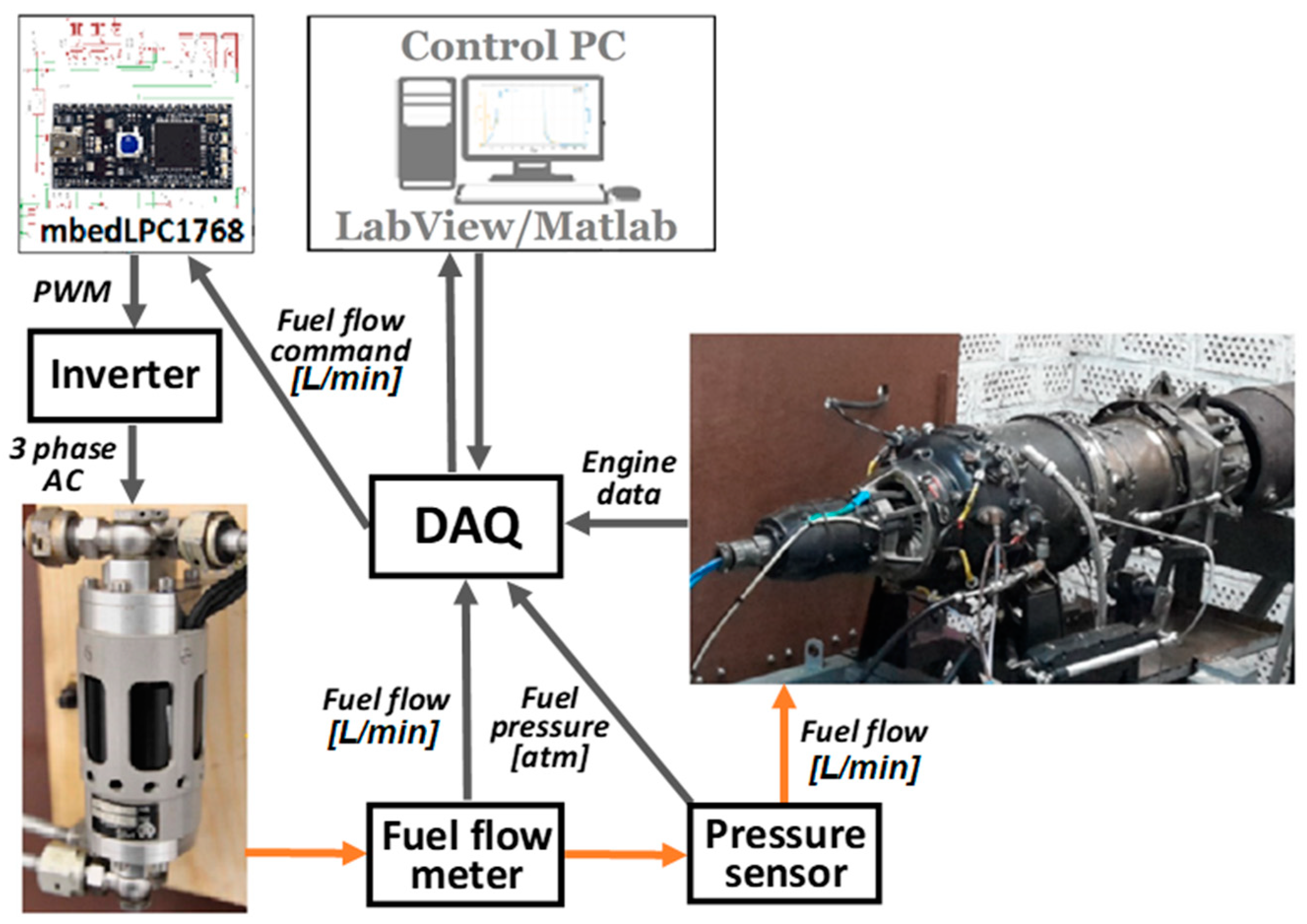
The block diagram of the iSTC-21v engine control is shown in Figure 1.
The control flow of the iSTC-21v, according to Figure 1, can be described as follows. The fuel stored in the fuel tank is gravity-fed through the fuel filters into the fuel/oil pump inlet. The pump is a speed-controlled BLDC motor which provides the required fuel supply to the engine. From the pump outlet, the fuel is led through a flow meter and pressure sensor directly to the fuel nozzles.
The components of the system, as shown in Figure 1, are as follows:
- Fuel-oil pump—a sensor-less BLDC motor, the rotor of which drives the fuel pump on one end and the oil pump on the other.
- Flow meter—Badger Meter, model MN2 SSPI-1, is an oval gear flow meter which measures the volumetric flow rate of fuel passing through the meter by repeatedly entrapping it with rotating parts. Its flow range is from 15 to 500 l/h, with a maximal temperature of 120 °C, accuracy of ±1% and maximal pressure of 5.5 MPa.
- Fuel pressure sensor—Siemens, model QBE 2002-P10 is suitable for the measurement of static and dynamic positive pressure. Its pressure range is from 0 to 1 MPa, temperature range from −40 to 80 °C and response time <5 ms.
- Inverter—three-phase inverter FOXY, model G2 R-60SB. Pulses are generated 50 times in a second and their width, which is directly proportional to the motor speed, can be in range of 1 ms to 2 ms.
The BLDC-motor-driven fuel-oil pump is the main power unit of the entire fuel-control system. One end of the motor’s rotor drives the fuel pump, and the other end drives the oil pump.
In our case, the three-phase, sensor-less BLDC motor with permanent magnets on the rotor and excitation coils on the stator was used. To control the BLDC motor speed and the associated fuel supply, the inverter was used. The PWM signal, generated by the mbed NXP LPC1768 microcontroller (Figure 2), was led into the input of the FOXY three-phase inverter (model G2 R-60SB), sensor-less BLDC and 8051-based microcontroller. The pulses are generated 50 times in a second and their width, which is directly proportional to the motor speed, can be in range of 1 ms to 2 ms.
The microcontroller’s platform is based on a 32-bit ARM processor with a frequency of 96 MHz. It contains 512 KB FLASH memory and 32 KB RAM. This microprocessor integrates a number of input/output interfaces, such as Ethernet, USB, CAN, I2C, SPI, as well as six 12-bit analog-to-digital converters, one 10-bit digital-to-analog converter and input/output pins capable of generating and measuring a PWM signal. The form of this microcontroller, as well as the function of the individual pins, is illustrated in Figure 2.
The chosen platform provides a sufficient performance and can be used for the implementation of the real-time operating system (RTOS). The advantage of the microcontroller is the number of communication interfaces and buses, which are directly integrated, thus eliminating the need to use additional modules.
3. Design of the Fuel-Flow Control Algorithms
A dynamic model of the fuel system was created using data measured on a specialized fuel system stand with a fuel-oil pump, sensors and nozzles. The model was then used in the design and simulation of all investigated control algorithms. The following control approaches were calculated and evaluated using the dynamic model:
- Direct inverse controller—the computationally simplest control algorithm,
- PID—the traditional proportionate–integral–derivative controller,
- Fuzzy PID controller—PID controller, the coefficients of which are adapted by a fuzzy inference system.
The aim of the controllers’ design was to create a controller with high efficiency and low complexity so it would not create any dynamic delays in the inner control loop of the iSTC-21v engine. The operability and feasibility of the controllers were tested in a simulation environment, and after this evaluation, the algorithms were tested on the fuel system stand, as well as the engine itself. To design control algorithms, a dynamic mathematical model of the fuel pump with its off-the-shelf electronic speed controller was created. The following sections will describe the design of the model and the individual control algorithms for the fuel pump.
3.1. Dynamic Model of the Fuel System
Based on the experimental identification, a non-linear mathematical model of the fuel-oil pump of the iSTC-21v engine was created. In general, its transfer function, designated Fpump(s), can be expressed as a first-order model with a non-linear gain approximation, as defined in Equation (1).
where:
- s—Laplace operator variable
- FF—Fuel flow [L/min]
- PWM—Pulse width modulation [μs]
- T—Time constant [s]
- KFF—Gain of the transfer function
- Td—Time delay constant [s].
The non-linearity of the model is expressed by the numerator of the transfer function: its gain. This gain of the fuel-pump model can be expressed as a dependence on the PWM signal, defined by its operating point and approximated by a polynomial (2). The polynomial coefficients a2, a1, a0 were computed by application of the least means square method using test stand data and the fuel-flow supply at stabilized operating points, as shown in Figure 3.
After inserting the gain function (2) into the basic model (1), the resulting dynamic model of the fuel pump is obtained (3):
The resulting model implemented as an algorithm, as shown in in Figure 4, was verified using data from a test bench with the fuel system, and the mean absolute percentage error of the model when compared to the obtained data was 1.82%, which makes it suitable to be used for initial testing and validation of the controller design. The output of the model when compared to the measured fuel flow on the fuel-flow test bench is shown in Figure 5.
3.2. Direct Inverse Control Design
The aim was to design the simplest possible controller without using feedback, and to test if such a controller can be sufficient for fast and precise fuel-flow metering. The input of the direct inverse controller is the commanded fuel flow—FFCMD—and its output is the required PWM signal. This means that the following transfer function needs to be created (5):
Because the dynamics of the fuel pump cannot be further improved past its time constant T = 0.3 s, it was decided to design the direct inverse controller only for the stabilized level of the fuel flow (the equilibrium point). This means that the equation of the direct inverse controller can be expressed as follows for the condition of the equilibrium point during the step-input response (6):
Because the fuel pump only operates at an interval of the fuel flow <0, 1.5> L/min, the full analytical solution of (6) is not necessary and inverse approximation is sufficient to decrease the complexity for implementation in a real-time small, embedded controller. The approximate direct inverse controller has therefore been calculated as (7):
The output of the direct inverse controller can then be expressed as (8):
After testing the inverse controller (8) connected with the model (4) in a simulated environment, implemented as presented in Figure 6, the simulation results shown in Figure 7 were obtained. The model is very precise in a simulated environment and can track the commanded fuel flow with a mean percentage absolute error of less than 1%. However, it is to be expected that the direct inverse controller will not be as successful in an experimental laboratory test as it lacks feedback, and the model is already working with an error. The result of a laboratory test bench should, however, be on par with the precision of the designed model.
3.3. PID Controller Design
The direct inverse control algorithm works well in a simulation environment; however, its main deficiency is that it is not able to compensate and rejects any external disturbance in the fuel system. It is to be expected that it will not be able to maintain the desired fuel flow in the real system. As a starting point, a basic PID controller was designed to track the desired fuel flow and to reject any disturbances. To simplify the design, the controller was designed on top of the direct inverse controller, which can be simply implemented in the ESC (electronic speed controller). The control loop is shown in Figure 8.
The controller was designed according to the basic equation, where its output (fuel-flow command PID) is defined as follows (9):
where P, I and D are the coefficients of the controller and N is the coefficient of the low-pass filter. The controller was calculated for the closed loop to be stable and critically damped with all real poles. The resulting controller, with a low-pass filter with a bandwidth of 20 rad/s, is defined as follows (10):
As the model of the fuel pump is quite simple, the expected behavior of the controller is stable with adequate dynamics, zero control error with no overshoot, as shown in Figure 9.
3.4. Fuzzy Adaptive PID Controller Design
The designed PID controller works on a satisfactory level in a simulation environment as shown in Figure 8; however, preliminary tests on a fuel test stand, as well as a turbojet engine, have shown that the performance of such a simple controller degrades a lot. This is because of stochastic processes ongoing in both the fuel systems and the engine itself as we deal with fluid dynamics and thermodynamic processes, which influence the fuel flow and operation of the fuel pump. One solution to this problem is to design a less aggressive PID controller with a higher robustness and higher stability margins. This, however, would be at the expense of the rise time, which would become unacceptable, hindering the performance of the whole engine. There are many approaches to solving this problem using methodologies, such as robust or LQ control; however, even these approaches cannot fully cover the specifics of the operation of a fuel pump connected to a turbojet engine. After many tests on a test stand, a knowledge base describing the behavior of the fuel pump was built, which yielded the construction of a simple adaptive PID controller, aimed to outperform the basic PID controller and contained a simple comprehensive rule base, which can be easily modified for other BLDC motor fuel pumps with different fuel flows, pressures and possibly fuels.
The implementation of the fuzzy adaptive controller is shown in Figure 10.
The model described above was used for the initial preliminary design of the fuzzy PID adaptor, which aimed to change the parameters of the PID controller to improve its dynamic response. For the design, a Takagi–Sugeno–Kang (TSK) fuzzy inference system was selected because it contains crisp values in consequent rules. The basic rule of the TSK adaptor was designed as follows (11):
This means that the inputs of the adaptor are the actual fuel flow produced by the fuel pump (FF), with values generated by the linguistic function L: FF->{Small (S), Big(B)} and the actual deviation (FFERR)/error from the commanded fuel flow (FFCMD), with values generated by the linguistic function L: FFERR->{Negative (N), Zero (Z), Positive (P)}. The fuzzy inference system produced three outputs defined as variables P, I, D with a linguistic function assigning values to each of them as L:{P,I,D}->{Small (S), Medium (M), Big(B)}. Because the Takagi–Sugeno FIS was used, the outputs are represented as crisp values. The membership functions for the parameter of fuel-flow error (FFERR) and fuel flow (FF) are shown in Figure 11 and Figure 12, and the gains of the PID controller are shown in Table 1.
The rule base for the fuzzy adaptive PID controller was designed to be as simple as possible with minimum rules to be comprehensive and easily implementable in digital-embedded controllers. The rules setting the controller gains are defined in the Table 2.
The results in a simulated environment are shown in Figure 13. It can be clearly seen that the fuzzy adaptive controller is performing well and slightly better than the standard PID controller. This behavior was expected; however, it is necessary to say that bigger differences in performance were expected on the laboratory test bench, which is described in the following section. The simulation confirmed that the design of the fuzzy adaptive controller was successful and ready for tests in real-world conditions.
4. Experimental Testing
Laboratory testing was conducted using two basic operational modes. The first one used a test bench utilizing only the oil/fuel system with only nozzles as shown in Figure 14. The second operational mode used the fully operational iSTC-21v engine on a test bench. In both cases, the same fuel-flow command signal was used, so the results could be directly compared to simulations and the design of the control system could be verified.
The test bench with only fuel nozzles yielded a quick re-evaluation of the designed controllers, without the need to run the whole engine, and a safe test of all the prototyped algorithms. To evaluate the efficiency of individual control approaches, the rise time and absolute control surface were used. Rise time describes how fast the controller reacts to a change in the command signal and the absolute value of the control surface as an integral of the control error, describing the overall quality and effort of the controller. The rise time was calculated as the time it takes the fuel flow to rise from 10% up to 90% of the final value. The absolute error surface was calculated as an integral of the absolute control error during one step of the command signal according to the following formula:
where:
- t0—time of the fuel-low command start (ignition)
- tf—time of the fuel-flow command end (shutdown).
The average rise time computed as a mean across all step changes in the commanded fuel flow was calculated to show the overall responsiveness of the controller. The absolute control surface was calculated from the ignition of the engine until its shutdown. These two metrics were selected because they are the most sensitive ones to show a good comparison of the designed control algorithms.
4.1. Tests on the Test Bench with Fuel Nozzles Only
All three control algorithms were at first tested on the test bench with fuel nozzles only, without running the engine connected, as illustrated in the scheme in Figure 14. The dynamic results are shown in Figure 15. All three controllers performed very well and in line with the simulations. As expected, the direct inverse controller was the fastest one; however, it was not able to compensate for external errors, which were not incorporated into the model it was derived from. The performance of all three controllers is shown in Table 3. The preliminary tests showed that the rule base of the fuzzy controller had to be modified. Rules number 1 and 2 had to be modified to decrease the integral coefficient of the controller to obtain better stability at low fuel flows with high loads. The resulting rule base is shown in Table 4 with the modified rules emphasized in grey and bold. This also shows that a major advantage of the fuzzy PID controller is that it can be modified to improve performance around certain operational points of the system without compromising/changing the performance of the controller in other areas of its operational envelope. The average rise time was calculated as mean rise and fall times across all step changes of the commanded fuel flow.
The best performing controller was the fuzzy adaptive PID controller, although the direct inverse controller was faster in rise time and was generally the most responsive, as expected, with the inability to compensate for external disturbances; thus, it was unable to produce zero deviation from the commanded fuel flow. The statistical values in Table 3 confirm this conclusion.
Because the tests on the test bench have been evaluated as successful, all three controllers were suitable for testing on a working turbojet engine.
4.2. Tests with a Working Engine iSTC-21v
The process of burning fuel in a combustion chamber creates other loads on fuel nozzles and the fuel pump in comparison to only running the experiment on a test bench without the engine. The same command signal was used so the results could be compared to the previous experiments. The engine was connected to the fuel pump as shown in Figure 1. For the tests with the engine, a modified rule base of the fuzzy adaptive PID controller presented in Table 4 was used. The resulting measurement using the DAQ system described in Section 2, and the obtained dynamic data, are presented in Figure 16, Figure 17 and Figure 18. Because the engine lights off at different times, all courses were synchronized for the moment of ignition to be comparable. This means that the measurement of the fuel flow starts at the moment the fuel is ignited in the combustion chamber, and this represents time 0, shown in Figure 16. The graph clearly shows that the direct inverse controller fails to deliver the required fuel supply with an average mean absolute difference of 0.08 l/min, which translates into the absolute error surface of 0.9 shown in Table 5. The PID and fuzzy PID controllers are comparable in performance at stable operating points; however, if this performance is expressed by the rotational speed of the engine, a difference up to 1000 rpm can be seen in Figure 17. The fuzzy adaptive PID controller had the best performance as shown by statistical indicators in Table 5, because it was better in transitional states with lower rise times, and it is also better in absolute error surface parameters. The designed direct inverse controller could not compensate all the loads and stochastic processes, which were created by the back pressure in the combustion chamber. The PID controller had an adequate performance, but there were fluctuations at lower fuel flows and the controller was slower during the transitional states. When looking at the resulting speed of the engine in Figure 17, all the performance effects are more pronounced.
The better operation of the fuzzy adaptive PID controller is also apparent when looking at the speed of the engine in Figure 17, where much smaller speed fluctuations can be seen, as well as faster acceleration of the engine. This means that the high-level controller of the engine has to work much less to stabilize its speed or thrust. The other design advantage of the adaptive PID controller lies in the fact that the rule base can be quickly tuned for other BLDC fuel pumps, which operate with higher or lower fuel flows and/or pressures, as well as other types of fuel.
The other main advantage of the fuzzy adaptive PID controller was its ability to maintain the required fuel-flow supply in a smoother manner, due to lower gains of its coefficients near zero deviations from the setpoint. This also resulted in a smoother start-up of the engine as shown in Figure 18, depicting dynamic start-up data. On the other hand, the fixed PID controller had a big delay because it was not aggressive enough at zero fuel flows. As a result, the direct inverse controller ignited the engine after 2 s, the fuzzy PID controller after 4 s, and it took nearly 11 s for the standard PID controller to ignite the engine. This also means that, during start-up, the adaptive controller consumed smaller volume of fuel compared to the standard PID. It is, however, just a preliminary find, which could be investigated and analyzed in follow-up studies and experiments.
5. Discussion
The fuzzy adaptive PID controller for the control of the fuel flow of a small turbojet engine has been developed as a proof of concept in this study. The aim was to create the simplest rule base with only five rules for two areas of control. This can be further expanded into three areas (low, medium and high), which could further improve the quality of the control of fuel flow. It could also be reduced into a single area with rules adapting the gains of the PID controller outside the steady state setpoint and inside it, based on the type of the fuel pump and the engine. The main advantage of the design is that it is simple and comprehensive, and it can be simply tuned for this type of fuel pump, fuel, or engine. The aggressiveness of the fuzzy PID controller can also be modified by adding a gain to its output. For lower time delays in the system, the fuel schedule of the fuzzy PID controller can be set to be more aggressive.
It is also important to note that the direct fuel pump behaves differently when connected to a running engine and without it, so the design should be based on a running engine. In conclusion, the fuzzy adaptive PID controller is around 30% more efficient than the standard PID and has the benefit of better characteristics during the start-up phase of the engine, translating into lower fuel consumption during start-up. Another benefit is that precise fuel metering of the engine can be expected in connection with a higher level of speed or thrust controllers, as these controllers will need a lower effort to control the engine, potentially further decreasing fuel consumption. The direct inverse controller has an expected steady-state error and cannot compensate for external disturbances, which limits its use to applications using an external feedback loop and higher-level controllers. A control strategy using fuzzy inference systems for switching a PID controller for steady states, and a direct inverse controller for transitions, could be also tested as follow-up research. Further optimization and evaluation of fuel consumption using different control strategies could be another path of future research. This paper offers all the coefficients, required models and underlying methodologies for further development of the precise fuel-flow control algorithms for small turbojet engines.
Author Contributions
Conceptualization, R.A.; Data curation, L.F. and R.A.; Formal analysis, L.F. and R.A.; Funding acquisition, L.F.; Investigation, L.F. and R.A.; Methodology, L.F. and R.A.; Software, L.F. and R.A.; Supervision, R.A.; Validation, L.F. and R.A.; Visualization, L.F.; Writing—original draft, L.F. and R.A.; Writing—review & editing, L.F. and R.A. All authors have read and agreed to the published version of the manuscript.
Funding
This work was supported by the Slovak Research and Development Agency under the Contract no. APVV-20-0546.
Institutional Review Board Statement
Not applicable.
Informed Consent Statement
Not applicable.
Data Availability Statement
Not applicable.
Conflicts of Interest
The authors declare no conflict of interest.
References
- Rezaei, A.; Dadouche, A. Development of a turbojet engine gearbox test rig for prognostics and health management. Mech. Syst. Signal Process. 2012, 33, 299–311. [Google Scholar] [CrossRef]
- Scholz, D.; Seresinhe, R.; Staack, I.; Lawson, C. Fuel consumption due to shaft power off-takes from the engine. In Proceedings of the 4th International Workshop on Aircraft System Technologies, Hamburg, Germany, 23–24 April 2013; Shaker Verlag: GmbH, Germany, 2013. [Google Scholar] [CrossRef]
- Cao, W.; Mecrow, B.C.; Atkinson, G.J.; Bennett, J.W.; Atkinson, D.J. Overview of electric motor technologies used for more electric aircraft (MEA). IEEE Trans. Ind. Electron. 2011, 59, 3523–3531. [Google Scholar] [CrossRef]
- Newman, R. The more electric engine concept. SAE Trans. J. Aerosp. 2004, 113, 1656–1661. [Google Scholar] [CrossRef]
- Beneda, K. Development of a modular FADEC for small scale turbojet engine. In Proceedings of the 2016 IEEE 14th International Symposium on Applied Machine Intelligence and Informatics (SAMI), Herlany, Slovakia, 21–23 January 2016; pp. 51–56. [Google Scholar] [CrossRef]
- Morioka, N.; Oyori, H. Fuel system design for the more electric engine. In Turbo Expo: Power for Land, Sea, and Air; American Society of Mechanical Engineers: New York, NY, USA, 2012; Volume 44670, pp. 767–774. [Google Scholar] [CrossRef]
- Sarala, P.; Kodad, S.F.; Sarvesh, B. Analysis of closed loop current controlled BLDC motor drive. In Proceedings of the 2016 International Conference on Electrical, Electronics, and Optimization Techniques (ICEEOT), Chennai, India, 3–5 March 2016; pp. 1464–1468. [Google Scholar] [CrossRef]
- Gamazo-Real, J.C.; Vázquez-Sánchez, E.; Gómez-Gil, J. Position and speed control of brushless DC motors using sensorless techniques and application trends. Sensors 2010, 10, 6901–6947. [Google Scholar] [CrossRef] [PubMed] [Green Version]
- Mamadapur, A.; Mahadev, G.U. Speed Control of BLDC Motor Using Neural Network Controller and PID Controller. In Proceedings of the 2019 2nd International Conference on Power and Embedded Drive Control (ICPEDC), Chennai, India, 21–23 August 2019; pp. 146–151. [Google Scholar] [CrossRef]
- Ramachandran, R.; Ganeshaperumal, D.; Subathra, B. Closed-Loop Control of BLDC Motor in Electric Vehicle Applications. In Proceedings of the 2019 IEEE International Conference on Clean Energy and Energy Efficient Electronics Circuit for Sustainable Development (INCCES), Krishnankoil, India, 18–20 December 2019; pp. 1–5. [Google Scholar] [CrossRef]
- Gobi, R.; Raja, S. Closed loop speed control of sensorless BLDC drive using direct BEMF method with PI controller. Int. Res. J. Eng. Technol. 2018, 5, 168–174. [Google Scholar]
- Kandiban, R.; Arulmozhiyal, R. Design of adaptive fuzzy PID controller for speed control of BLDC motor. Int. J. Soft Comput. Eng. 2012, 2, 386–391. [Google Scholar]
- Neethu, K.; Boopathi, M.; Mannayee, G.; Kanish, T.C. Fuzzy logic based speed control of BLDC motor on sensorless technique for space applications. Indian J. Sci. Technol. 2016, 9, 1–9. [Google Scholar] [CrossRef] [Green Version]
- Ch, L.; Palakeerthi, R. BLDC Drive Control using Artificial Intelligence Technique. Int. J. Comput. Appl. 2015, 118, 5–9. [Google Scholar] [CrossRef]
- Ramírez-Cárdenas, O.D.; Trujillo-Romero, F. Sensorless speed tracking of a brushless DC motor using a neural network. Math. Comput. Appl. 2020, 25, 57. [Google Scholar] [CrossRef]
- Dini, P.; Saponara, S. Design of Adaptive Controller Exploiting Learning Concepts Applied to a BLDC-Based Drive System. Energies 2020, 13, 2512. [Google Scholar] [CrossRef]
- Huh, N.; Park, H.S.; Lee, M.H.; Kim, J.M. Hybrid PWM Control for Regulating the High-Speed Operation of BLDC Motors and Expanding the Current Sensing Range of DC-link Single-Shunt. Energies 2019, 12, 4347. [Google Scholar] [CrossRef] [Green Version]
- Shao, J.; Nolan, D.; Teissier, M.; Swanson, D. A novel microcontroller-based sensorless brushless DC (BLDC) motor drive for automotive fuel pumps. IEEE Trans. Ind. Appl. 2003, 39, 1734–1740. [Google Scholar] [CrossRef]
- Liu, Q.; Ma, R.; Han, W.; Zhang, Q. A reliable starting method of sensorless brushless DC motor for aviation fuel pumps. In Proceedings of the 2016 35th Chinese Control Conference (CCC), Chengdu, China, 27–29 July 2016; pp. 4740–4744. [Google Scholar] [CrossRef]
- Tsai, C.C.; Lin, S.C.; Huang, H.C.; Cheng, Y.M. Design and control of a brushless DC limited-angle torque motor with its application to fuel control of small-scale gas turbine engines. Mechatronics 2009, 19, 29–41. [Google Scholar] [CrossRef]
- Andrs, O.; Vetiska, J.; Holub, M.; Kovar, J. Model Based Design of Fuel Pump Control. Appl. Mech. Mater. 2016, 821, 601–607. [Google Scholar] [CrossRef]
- Ding, R.; Xiao, L.; Jin, X. Robust Control for Electric Fuel Pump with Variant Nonlinear Loads Based on a New Combined Sliding Mode Surface. Int. J. Control Autom. Syst. 2019, 17, 716–728. [Google Scholar] [CrossRef]
- De Cesare, M.; Parotto, M.; Covassin, F.; Sgatti, S. Electric low pressure fuel pump control for fuel saving (No. 2013-01-0339). In Proceedings of the SAE 2013 World Congress & Exhibition, Detroit, MI, USA, 16–18 April 2013. [Google Scholar] [CrossRef]
- Montazeri-Gh, M.; Yousefpour, H.; Jafari, S. Fuzzy logic computing for design of gas turbine engine fuel control system. In Proceedings of the 2010 2nd International Conference on Computer and Automation Engineering (ICCAE), Singapore, 26–28 February 2010; Volume 5, pp. 723–727. [Google Scholar] [CrossRef]
- Andoga, R.; Főző, L.; Judičák, J.; Bréda, R.; Szabo, S.; Rozenberg, R.; Džunda, M. Intelligent situational control of small turbojet engines. Int. J. Aerosp. Eng. 2018, 2018, 8328792. [Google Scholar] [CrossRef]
Figure 1.
Block diagram of iSTC-21v engine control.

Figure 2.
The microcontroller mbed NXP LPC1768.

Figure 3.
Non-linear approximation of gain KFF of the fuel pump’s dynamic model.

Figure 4.
The implemented structure of the dynamic model of the fuel pump with non-linear approximation.
Figure 4.
The implemented structure of the dynamic model of the fuel pump with non-linear approximation.

Figure 5.
Comparison of the data measured on a fuel test bench and data from the dynamic model.

Figure 6.
Implementation of the direct inverse controller in simulation environment.

Figure 7.
Direct inverse control—dynamic simulation.

Figure 8.
Implementation of the PID controller in simulation environment.

Figure 9.
PID control—dynamic simulation.

Figure 10.
Fuzzy adaptive PID controller in simulation environment.

Figure 11.
Fuzzy membership functions for the parameter of fuel-flow error.

Figure 12.
Fuzzy membership functions for the parameter of fuel flow.

Figure 13.
Fuzzy adaptive PID performance during a simulated fuel-flow run.

Figure 14.
Fuzzy adaptive PID performance during a simulated fuel-flow run.

Figure 15.
Performance of the controllers on a test bench.

Figure 16.
Performance of the controllers with running engine—iSTC-21v.

Figure 17.
Speed of the iSTC-21v engine with different fuel flow controllers.

Figure 18.
Performance of the controllers during start-up of the engine.


Table 1.
The values of the output variables of the TSK controller.
| P | I | D | |
|---|---|---|---|
| Z | 0 | 0 | 0 |
| PS | 0.17 | 0.6 | 0.05 |
| PM | 0.37 | 1.2 | - |
| PB | 0.6 | 1.8 | - |
Table 2.
The rule base of the fuzzy inference system.
| Inputs | Outputs | |||||
|---|---|---|---|---|---|---|
| Linguistic Variable | FFERR | FF | P | I | D | |
| Rule No. | ||||||
| 1 | N | S | PB | PB | Z | |
| 2 | P | S | PB | PB | Z | |
| 3 | N | B | PM | PM | Z | |
| 4 | P | B | PM | PM | Z | |
| 5 | Z | - | PS | PS | PS | |
Table 3.
Performance of the controllers on the test bench with fuel nozzles.
| Controller | Average Rise Time (s) | Absolute Error Surface |
|---|---|---|
| Direct inverse model | 0.4 | 0.33 |
| PID controller | 2.1 | 0.3 |
| Fuzzy PID controller | 1.15 | 0.26 |
Table 4.
The modified rule base of the adaptive fuzzy PID controller.
| Inputs | Outputs | |||||
|---|---|---|---|---|---|---|
| Linguistic Variable | FFERR | FF | P | I | D | |
| Rule No. | ||||||
| 1 | N | S | PB | PS | Z | |
| 2 | P | S | PB | PS | Z | |
| 3 | N | B | PM | PM | Z | |
| 4 | P | B | PM | PM | Z | |
| 5 | Z | - | PS | PS | PS | |
Table 5.
Performance of the controllers on the test bench with fuel nozzles.
| Controller | Average Rise Time (s) | Absolute Error Surface |
|---|---|---|
| Direct inverse model | - | 0.9 |
| PID controller | 3.1 | 0.36 |
| Fuzzy PID controller | 2.26 | 0.29 |
Publisher’s Note: MDPI stays neutral with regard to jurisdictional claims in published maps and institutional affiliations. |
© 2022 by the authors. Licensee MDPI, Basel, Switzerland. This article is an open access article distributed under the terms and conditions of the Creative Commons Attribution (CC BY) license (https://creativecommons.org/licenses/by/4.0/).
Share and Cite
MDPI and ACS Style
Főző, L.; Andoga, R. Advanced Control of an Electric Fuel-Oil Pump for Small Turbojet Engines. Aerospace 2022, 9, 607. https://doi.org/10.3390/aerospace9100607
AMA Style
Főző L, Andoga R. Advanced Control of an Electric Fuel-Oil Pump for Small Turbojet Engines. Aerospace. 2022; 9(10):607. https://doi.org/10.3390/aerospace9100607
Chicago/Turabian StyleFőző, Ladislav, and Rudolf Andoga. 2022. "Advanced Control of an Electric Fuel-Oil Pump for Small Turbojet Engines" Aerospace 9, no. 10: 607. https://doi.org/10.3390/aerospace9100607
Note that from the first issue of 2016, this journal uses article numbers instead of page numbers. See further details here.