
Numerical Modeling of Heat Exchanger Filled with Octahedral Lattice Frame Porous Material

1
College of Energy and Power Engineering, Nanjing University of Aeronautics and Astronautics, Nanjing 210016, China
2
Jiangsu Province Key Laboratory of Aerospace Power System, Nanjing University of Aeronautics and Astronautics, Nanjing 210016, China
*
Authors to whom correspondence should be addressed.
Aerospace 2022, 9(5), 238; https://doi.org/10.3390/aerospace9050238
Submission received: 8 March 2022
/
Revised: 6 April 2022
/
Accepted: 19 April 2022
/
Published: 26 April 2022
(This article belongs to the Special Issue Thermophysics and Heat Transfer for Aerospace Applications)
Abstract
:A numerical investigation into the fluid flow and heat transfer process in a 3D-printed shell-and-tube heat exchanger was carried out. The shell side of the heat exchanger was inserted with octahedral lattice frame porous material to enhance the heat transfer. In order to avoid establishing a complex grid system, the porous material of the shell side was modeled by a porous media model. The non-equilibrium model was adopted for the modeling of the heat exchange between the solid and fluid in porous media. An experimental investigation was carried out to validate the feasibility of this approach. The result indicates that the simplified approach is capable of providing an appropriate prediction of the pressure drop and heat transfer efficiency with moderate computational resources. The average error of pressure loss and heat transfer effectiveness is within 4% and 6.1%.
1. Introduction
With the development of propulsion technology, the heat loads in aero-engines are increasingly prominent and dealt with through thermal management. Williams et al. [1] pointed out that the demand for a high-capability thermal management system is increasing, while the weight and volume of such as system remains unchanged or even reduced. Heat exchangers, which deal with heat transfer between hot and cold fluids, are crucial in thermal management system design. New technology which brings compact, light, efficient heat exchangers with low flow resistance has become key for the development of future thermal management systems.
As an outstanding representative of the approaches to enhance heat transfer, porous material filling, which has many advantages, such as being lightweight and having a high compactness, has been widely applied in the designing of compact heat exchangers and heat sinks [2,3,4]. Generally, porous materials used for heat transfer enhancement such as metal foams, fibers or packed beds spheres are much more intricate compared to traditional fins used for heat exchangers. It is difficult to grasp the microflow and heat transfer characteristics, and the microscopic structure is uncontrollable in the course of manufacture. When optimizing the structure of porous materials, the parameters that can be changed are very limited, and most of them are macroscopic parameters such as pore density and porosity. In recent years, the development of 3D printing technology has brough a high degree of freedom to the manufacturing of porous materials [3,5].
Son et al. [5] proposed a multifunctional tetrahedral lattice frame porous material for heat exchangers. Both experimental and numerical studies were carried out, which indicated that this porous material can provide high porosity, high compactness, a low pressure drop and high structural integrity. Krishnan et al. [6] proposed several complex structured monolithic heat sinks. Numerical simulations and experiments were undertaken to obtain the fluid flow and heat transfer parameters. The fabrication of these heat sinks was achieved by 3D printing and investment casting. Ren et al. [7] proposed shell-and-tube heat exchangers for aero-engine thermal management systems which are filled with octahedral lattice frame porous material. A study on flow and heat transfer was carried out both numerically and experimentally, and the results show that the porous structure can improve the heat transfer efficiency of the heat exchanger but will also increase the flow resistance.
Numerical simulations are an important means of heat exchanger research, and can provide results with moderate accuracy if the computational model adopted is reasonable. Normally, it needs huge computational resources to carry out a numerical simulation of the whole heat exchanger. For example, 150 million grid cells are needed for the simulation of flow in a shell-and-tube heat exchanger composed of 500 tubes and 10 baffles [8]. For those heat exchangers filled with porous media, the complexity of the internal structure is much higher than that of conventional heat exchangers. In order to make the calculation of flow and heat transfer more accurate, the tiny gap in porous media requires grids to be of high resolution, which leads to the size of the grid system exceeding the computational capability of most computers and workstations.
One solution to relieve the unacceptable computational burden is the use of periodic and symmetry boundaries to simplify the computational model of the heat exchangers. Boomsma et al. [9] established a 4.6 mm × 4.6 mm × 4.6 mm cell with an ideal periodic unit which represents the structure of open-cell metal foam. Numerical simulations were carried out by using a grid system with 169,266 vertices, and the predicted pressure drop is 25% lower than the experimental data. Heltzel [10] carried out numerical simulation research on a counterflow heat exchanger filled with porous material. The heat exchanger was simplified into a small periodic portion containing two channels with 1 mm × 1 mm × 4.5 mm porous media filled in. A grid system with more than 2,000,000 nodes was created in order to achieve an independent solution. Dong and Xie [11] numerically studied the mass dispersion process of methane and air in porous media; the porous media were simplified as a three-dimensional array of cylindrical rods with a staggered arrangement. The results showed good agreement with the experimental data. It should be notice that simplification approaches which involve using a cell unit to represents the whole heat exchanger are only applicable when heat exchangers have a symmetrical or periodic structure.
Another method is to model porous medium as a region with pre-defined flow resistance and heat transfer characteristics, which avoids the establishment of grids for the complex structure in the heat exchanger, thus reducing the number of grids required for modeling [12]. This approach is widely used in the numerical simulation of heat exchangers. Prithiviraj and Andrews [8,13] performed a numerical simulation of a shell-and-tube heat exchanger. The pressure drop caused by fluid flowing through the heat exchanger was predicted by the distributed resistance method, and the heat transfer coefficient was derived from the empirical heat transfer correlation to predict the heat transfer between the shell-and-tube side in the heat exchanger. Missirlis et al. [14] carried out a numerical simulation of an recuperative heat exchanger for an aero-engine. The pressure loss calculated by the porous medium model was in good agreement with the experimental results. Yakinthos et al. [15] developed a porous medium model for a recuperator which took the influence of the inclination angle, attack angle and heat transfer on the pressure drop law into consideration. Miranda and Anand [16] numerically investigated the convective heat transfer in a channel with porous baffles. The extended Darcy–Forchheimer model was used to model the flow resistance through the porous baffles.
Using the porous media heat transfer model, the energy equation can be modeled by the local thermal equilibrium (LTE) model or local thermal non-equilibrium (LTNE) model [17]. Lin et al. [18] studied the influence of different heat transfer models on heat transfer prediction for the aluminum foam. They pointed out that the influence of non-equilibrium models is more accurate than that of equilibrium models, and when the flow velocity is higher or the height of the aluminum foam is higher, both models can obtain accurate results. Wang and Guo [19] proposed a new method to calculate the volume heat transfer coefficient based on the assumption that the porous media structure is a cubic skeleton. By taking the effect of heat conduction into consideration, this method can predict the heat transfer process more accurately than conventional approaches. Alazmi and Vafai [20] studied the influence of eight different boundary conditions on the heat transfer in non-equilibrium model, and pointed out that different boundary treatments have a great influence on the calculation results. Ouyang et al. [21] proposed a thermal boundary condition model for the local thermal non-equilibrium model for convection heat transfer in porous media. In order to solve the complex coupling relationship at the interface between the fluid, solid and porous media, the wall was artificially split into two phases with different temperatures. These two phases were coupled with a fluid and solid in porous media, respectively. Trilok et al. [22] numerically investigated the heat transfer of metal foams of orderly varied pore density and porosity was analyzed under various convection regimes, LTNE was selected for heat modeling and the Darcy–Forchheimer law was selected for flow modeling. Jadhav et al. [23] conducted a multiobjective optimization of pipes partially filled with metal foam using a numerical approach. LTNE is utilized for heat transfer modeling.
In this paper, a simplified numerical method is proposed for the modeling of the flow and heat transfer characteristics of a heat exchanger filled with octahedral lattice frame porous material. Specifically, the flow resistance model of the shell side is established by treating porous media as a clear zone with predefined flow loss characteristics; the heat transfer between porous media, the wall and the fluid is established based on the non-equilibrium model. The parameters of the porous media model for flow loss and heat transfer are obtained by performing a numerical simulation on the unit cell. An experimental investigation is also presented to verify the feasibility of the simplified method.
2. Materials and Methods
2.1. Experimental Setup
As shown in Figure 1, the experimental system consists of 4 main components: hot air supply passage, water supply passage, heat exchanger test section and measuring devices. The air is supplied by a screw air compressor and the water is pumped from a water tank by a submersible motor pump. The air is then heated by an electric heater which is powered by a regulative DC power supply and then enters the test section.
The tested heat exchanger is a shell-and-tube heat exchanger which consists of core body, water main tubes, water collector, air main tubes and air collector, as shown in Figure 2a,b. The water collector is a semicircular chamber with a diameter of 20 mm. The water enters the chamber from water main tubes with 10 mm diameter and then distributed to 14 tubes in the core body. The air collector is a chamfered rectangular chamber, where the air enters from 3 tubes, with diameters of 15 mm, and then enters the shell side of the heat exchanger.
The core body consists of the tubes and the shell side filled with octahedral lattice frame porous material, which is manufactured by 3D-printing technology. The material is aluminum alloy (AlSi10Mg). It is 110 mm in length, 100 mm in width, and 20 mm in height. Figure 2c,d present the geometry of the heat exchanger’s core body. The outer diameter of the tubes in the heat exchanger is 6 mm and the wall thickness is 1 mm. The tube bundles are arranged in an aligned arrangement, the transverse spacing ST is 12 mm and longitudinal spacing SL of the tube bundle is 24 mm. The porous media are composed of periodically repeated octahedron structure whose edges are all metal pillars of the same length, 6 mm. The diameter of the pillars is 1.2 mm, and the porosity is 0.82, as shown in Figure 2e.
Two sets of experimental tests were carried out, one for heat transfer performance and another for the pressure loss characteristics of the shell side. Tests for pressure loss characteristic were performed under cold conditions. The mass flow rate of the shell side was adjusted within the range 0.005 to 0.0116 kg/s. The flow loss of the heat exchanger is characterized by pressure drop between the inlet and the outlet.
where the subscripts s and t represent shell-side and tube-side flow, respectively. Pressure drop was measured by a differential pressure gauge and the impulse pipe is located upstream and downstream of the main air tubes. An investigation of heat transfer performance was carried out to determine the heat transfer effectiveness under different tube side mass flow rates. The mass flow rate of the shell side was fixed at 0.00833 kg/s and the temperature was 323 K. The mass flow rate of the water varied from 0.00556 to 0.01667 kg/s and the temperature was fixed at 289 K. The heat transfer effectiveness is defined as:
The temperatures were measured by PT100 temperature sensors located at inlet and outlet of the heat exchanger. In order to reduce the heat loss, the test section was wrapped with thermal insulation material.
Within the current test range mentioned above, the differential pressure gauge had an accuracy of approximately 99.5%. The measured error of the flow meter for water was below ±1.5%, and the measured error of the flow meter for air was below ±2%. For the temperature measurement, the error was estimated to be within 0.5 K.
The error between the experiment and numerical simulation can be expressed as:
2.2. Computational Modeling
2.2.1. Grid Generation and Boundary Conditions
According to the physical model in the previous part of this paper, the grid system used for the simplified method is presented in Figure 3. The shell side filled with lattice frame material was treated as a porous media region with pre-defined flow resistance and heat source, which avoids the establishment of grids for the complex structure. Unconstructed grids were constructed for the current study. The grids near the wall were refined and 5 inflation layers were used. From the grid sensitivity test, a grid system with about 1,100,000 cells was selected. The value of the y+ is less than 2.
The boundary conditions for the inlets and outlets of both the shell and tube sides were set to be consistent with the experimental test, as shown in Table 1. Air was treated as an incompressible ideal gas, where the density, viscosity and thermal conductivity are only affected by temperature, since the temperature rise of water was not significant. The properties of water were constant. The thermal conductivity of the tube wall was set at 100 W/(m·K).
2.2.2. Flow and Heat Transfer Modeling
Considering flow modeling, the flow resistance can be modeled by adding a momentum source term into the flow equation for the porous media zone:
where u is the velocity of the fluid, ui is the component velocity in each direction, μ is the viscosity of the fluid, and ρ is the density of the fluid. C1 and C2 are the viscous and inertial coefficients, which are determined by the specific structure of the porous media.
The SST k-ω turbulence model was chosen to model turbulence. The transport equations for k and ω are given by the following [24]:
The constants involved in this turbulence model were set as: β1 = 0.075, β2 = 0.0828, α1 = 5/9, α2 = 0.44, σω1 = 2, σω2 = 1/0.856, and σk1 = 2, σk2 = 1.
For heat transfer modeling, the non-equilibrium model is adopted, where the porous medium and fluid flow are not in thermal equilibrium. The treatment porous medium and fluid flow temperature is the same as that proposed by Ouyang [21], where the porous media zone consists of two zones (one for fluid and one for solid), which coincide with each other. These two zones interact only by heat transfer. For the solid wall zone, it is assumed that pillars of the lattice frame material are inserted into the wall, so the wall zone also contains by solid with a proportion of ε and porous material with a proportion of (1 − ε), as shown in Figure 4. That is to say, the solid wall zone also consists of two zones which interact by heat transfer.
For the porous media zone, the energy equation of porous media can be expressed as follows:
The energy equation of the fluid can be expressed as:
where the source term S represents heat transfer between porous media and fluid, which can be expressed as:
where λf is the thermal conductivity of the fluid and λp is the thermal conductivity of the porous media. TP is the temperature of porous media, Tf is the temperature of fluid, and Cf is the specific heat capacity of fluid. hp is the heat transfer coefficient, which can be obtained from the Nusselt number calculated from the local physical property and velocity. α is the heat transfer area per unit volume, which is determined by the structure of the porous media.
For the solid wall zone, in addition to the heat conduction of the pillars and the solid itself, there is also heat conduction between the pillar and the wall due to the temperature difference. Therefore, the energy equation can be expressed as:
where λs is the thermal conductivity of the solid. It should be noted that the thermal conductivity of the pillar inside the wall porous region is one-dimensional and perpendicular to the tube wall, and its thermal conductivity can be expressed as (1 − ε) λs. Ts is the temperature of the solid, and δ is the thickness of the heat conduction between the porous media and the pillar in the pipe wall, which is the radius of the pillar.
There is a coupling surface between the solid wall zone and porous media zone, on which two sets of energy exchange relations exist, namely, the convection heat transfer between the fluid and the wall and the heat conduction between the porous media in the wall and the porous media in the fluid:
The computation was conducted using the commercial software ANSYS Fluent, with an integration of the user-defined function (UDF) for the calculation of the heat transfer in porous media zone. The SIMPLEC solver was used for the pressure–velocity coupling. The second-order upwind discretization was adopted to discretize the momentum, energy and turbulence transport equations. The energy and UDS residuals were set to 10−6, and the other residuals were set to 10−5 as the convergence criteria.
2.2.3. Parameters Needed for Porous Media Modeling
As mentioned above, for the modeling of the porous media, parameters such as the heat transfer coefficient, thermal conductivity and the values of C1 and C2 are still needed. Compared with conventional porous media such as metal foam, there are two main differences. First of all, the structure of foam metal is disordered and its parameters are normally obtained by experiment, while the octahedral lattice has a periodical repeated structure. Therefore, when constructing a flow and heat transfer model, the required parameters can be obtained through numerical simulation by the establishment of a unit body and the use of periodic conditions, as shown in Figure 5. In addition, most porous media such as metal foam can be treated as isotropic. When it comes to octahedral structures, although they are symmetrical in the x and y directions, their characteristics in the z direction are different, which should be considered in the modeling. A numerical simulation was carried out for the smallest cell unit of the octahedral lattice frame material. The grid system used is shown in Figure 5. Unconstructed grids were adopted for the current study. The grids near the wall were refined and 5 inflation layers were used. The value of the y+ is less than 2. From the grid sensitivity test, a grid system with about 680,000 cells was selected.
The two planes in the vertical x direction were set as the periodic boundary at the specified mass-flow rate, and the corresponding inlet velocity was from 6 to 20 m/s, and the inlet temperature was fixed at 300 K. The wall was set as a constant wall temperature boundary, the temperature TW = 350 K, the inlet and outlet were selected as the periodic boundary conditions, and the other surfaces were set as the symmetry boundary conditions. The Reynolds number of the incoming flow can be calculated by the following formula:
where u is the inlet velocity and d is the diameter of the octahedral pillar. By monitoring the wall heat flux qW, the Nusselt numbers corresponding to different Reynolds numbers are calculated as:
where hp is the average convective heat transfer coefficient of porous media obtained by numerical simulation:
The relationship between the Nusselt number and Reynolds number is obtained by a curve fitting procedure:
Similarly, by calculating the pressure loss per unit length corresponding to different inflow velocities, C1 and C2 are also obtained:
A numerical simulation was also carried out to confirm the thermal conductivity of porous media, as shown in Figure 6. Face 1 and face 2 are perpendicular to the x direction, and face 3 and face 4 are perpendicular to the z direction.
When calculating the thermal conductivity in the x direction, face 1 was set as the constant heat flux wall boundary condition with the heat flux equals to 5000 W/m2; face 2 was set as the constant temperature wall boundary condition. The temperature was set as T2 = 350 K, and the other faces were set as symmetrical boundaries. Additionally, the thermal conductivity of the porous media is λpx:
where a1 is the area of face 1 and Ax is the area in x direction corresponding to the cuboid wrapping of the structure, as shown in Figure 6.
Since the structure of the octahedron is consistent in the x and y directions, the thermal conductivity in the y direction is the same as that of the x direction.
When calculating the thermal conductivity in the z direction, face 3 is set as the constant heat flux wall, the heat flux density is q = 5000 W/m2, face 4 is set as the constant wall temperature boundary condition, the temperature T4 is set as 350 K, and the other faces are set as the symmetry boundary conditions. The thermal conductivity of the porous media is λpz:
where a3 is the area of face 3 and Az is the area perpendicular to the z direction corresponding to the cuboid wrapping of the structure, as shown in Figure 6.
3. Validation of the Method
Figure 7 shows a comparison between the calculation and experimental results of the pressure drop under different shell-side mass flow rates ms. From the figure, we can see that the shell-side flow loss increases with ms in a quadratic mode, which can be correctly reflected by the numerical simulation. Compared with the experimental data, the average error of flow loss is as high as 4%. The CFD simulations consistently underpredict the pressure drop. This may be because in the actual heat exchanger, when the fluid enters the core from the air-collecting chamber, the flow velocity increases due to the sudden flow area reduction caused by the porous material, which will cause excess flow loss. Similarly, when the fluid flows out of the core, the flow area increase will also cause flow loss. In the porous media model, the porous material is treated as a clear zone, so the flow loss is underestimated.
Figure 8 presents the tested and calculated heat transfer effectiveness verses tube side mass flow rate. The graph shows that the heat transfer effectiveness of the heat exchanger rises with the increase in the mass-flux ratio. As the tube side mass flow rate mt grows from 0.00566 kg/s, the heat transfer effectiveness increases rapidly. When mt reaches up to 0.0111 kg/s, the trend of increase tends to be flatter gradually. The numerical simulation results are slightly lower than the measured value in the experiment, where the average deviation is within 6.1%. This may be because the establishment of heat transfer parameters of porous media is based on a periodic cell unit, which is based on the assumption that the flow is fully developed. However, in fact, the flow in the heat exchanger is more complex, and the model ignores the enhancement of heat exchange by the inlet effect.
4. Discussion
The velocity distribution in the heat exchanger is shown in Figure 9, Figure 10 and Figure 11. For the shell side, the mal-distribution for the air flow occurs only in the first and last rows of the tube bundle. The air enters a rectangular space of the heat exchanger through a circular inlet with non-uniform velocity caused by the elbow of the tubes. As the air flows downstream, the tube bundle regulates the flow field like a distributer, which makes the velocity distribution uniform. When the air flows out of the rectangular cavity, the flow converges to the circular outlet again, which affects the flow distribution of the last row. For the tube side, the mal-distribution is more severe. The water flow is mainly concentrated in tubes facing the inlet. As is shown in Figure 12, the velocity distribution on the tube side follows the same pattern under different mass flow rates. The velocity in the other tubes is almost the same except for tubes 6 to 9 and the velocity in tubes 7 and 8 is almost two times higher than that in other tubes.
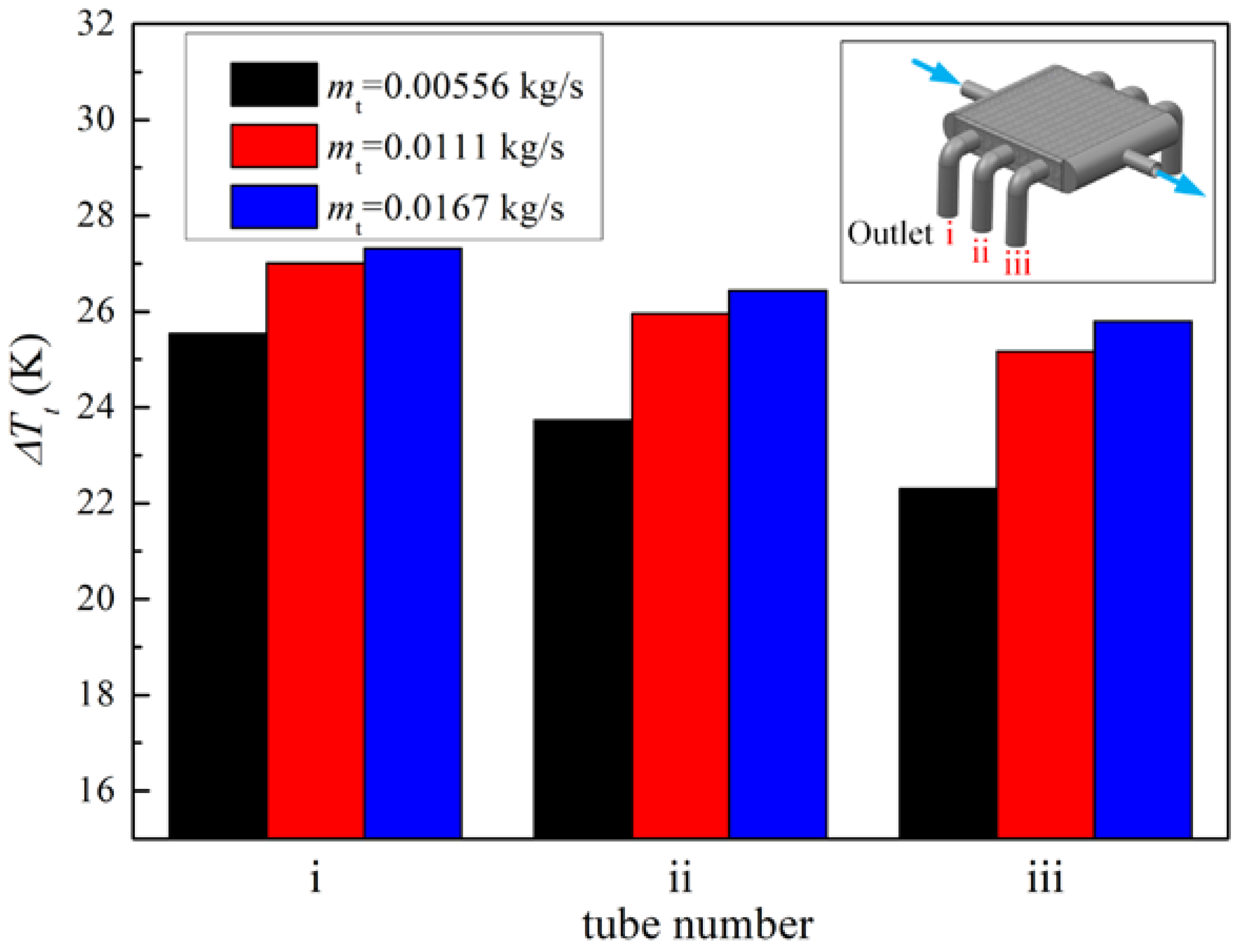
When it comes to heat transfer, the temperature distribution of the shell side is also non-uniform. As shown in Figure 13 and Figure 14, the temperature of the air and solid near the tube side inlet is significantly lower than that near the tube side outlet. With the increase in the tube-side mass flow rate mt, the heat transfer between the tube and shell side is enhanced significantly. This phenomenon occurs due to two reasons: On the one hand, the increase in the flow rate makes the internal flow more difficult to heat. The decrease in the internal flow temperature leads to the increase in the temperature difference between the internal and external flows, which leads to the increase in the total heat transfer rate, as shown in Figure 15 and Figure 16. On the other hand, the increase in the heat transfer coefficient in the tube leads to the decrease in tube-side thermal resistance, which increases the total heat transfer coefficient, as shown in Figure 17; although the Nusselt number of shell side is almost constant, the Nusselt number of the tube side increases sharply with the increase in the Reynolds number. Figure 18 and Figure 19 shows the temperature distribution of the tube wall and porous material of the heat exchanger at different mt. It can be seen from the figure that the increase in the tube-side mass flow rate reduces the temperature of porous material and tube wall, thus enhancing heat exchange between the shell side and tube side. This effect becomes less obvious with the further increase in flow, as the temperature distribution is similar for Figure 18 b,c. It can also be seen that the non-uniformity of the temperature distribution is also alleviated with the increase in mt, as shown in Figure 20.
5. Conclusions
In this paper, a numerical investigation of a 3D-printed shell-and-tube heat exchanger was conducted with the adoption of a simplified numerical method. An experimental investigation was carried out to verify the feasibility of the simplified method. The results show that the simplified method proposed in this paper can accurately predict the heat transfer process and flow loss characteristics in the heat exchanger with moderate calculation resource consumption. Compared with the experimental results, the average error of pressure loss and heat transfer effectiveness is within 4% and 6.1%, separately. The pressure loss rises with the increase in the tube-side mass flow rate in a quadratic mode. With the increase in the shell-side mass flow rate mt, the heat transfer effectiveness keeps increasing and tends to be stable when mt reaches 0.011 kg/s.
Author Contributions
Conceptualization, B.Z., J.Z. and W.L.; methodology, B.Z., W.L.; validation, B.Z., J.Z. and W.L.; formal analysis, B.Z., J.Z. and W.L.; investigation, B.Z.; data curation, B.Z.; writing—original draft preparation, B.Z.; writing—review and editing, J.Z.; visualization, B.Z.; supervision, J.Z.; project administration, J.Z.; funding acquisition, J.Z. All authors have read and agreed to the published version of the manuscript.
Funding
This research was funded by National Science and Technology Major Project, grant number: 2017-III-0011-0037.
Data Availability Statement
Not applicable.
Conflicts of Interest
The authors declare no conflict of interest.
References
- Williams, M.; Muley, A.; Bolla, J.; Strumpf, H. Advanced Heat Exchanger Technology for Aerospace Applications; SAE International: Warrendale, PA, USA, 2008; pp. 2688–3627. [Google Scholar] [CrossRef]
- Han, X.H.; Wang, Q.; Park, Y.G.; T’Joen, C.; Sommers, A.; Jacobi, A. A Review of Metal Foam and Metal Matrix Composites for Heat Exchangers and Heat Sinks. Heat Transf. Eng. 2012, 33, 991–1009. [Google Scholar] [CrossRef] [Green Version]
- Smith, B.H.; Szyniszewski, S.; Hajjar, J.F.; Schafer, B.W.; Arwade, S.R. Steel Foam for Structures: A Review of Applications, Manufacturing and Material Properties. J. Constr. Steel Res. 2012, 71, 1–10. [Google Scholar] [CrossRef] [Green Version]
- Hung, T.C.; Yan, W.M. Optimization of Design Parameters for a Sandwich Distribution Porous Microchannel Heat Sink. Numer. Heat Transf. Part A Appl. 2014, 66, 29–251. [Google Scholar] [CrossRef]
- Son, K.N.; Weibel, J.A.; Kumaresan, V.; Garimella, S.V. Design of Multifunctional Lattice-Frame Materials for Compact Heat Exchangers. Int. J. Heat Mass Transf. 2017, 115, 619–629. [Google Scholar] [CrossRef] [Green Version]
- Krishnan, S.; Hernon, D.; Hodes, M.; Mullins, J.; Lyons, A.M. Design of Complex Structured Monolithic Heat Sinks for Enhanced Air Cooling. IEEE Trans. Components Packag. Manuf. Technol. 2012, 2, 266–277. [Google Scholar] [CrossRef]
- Ren, Y.X.; Yu, X.; Zhang, X.Z.; Cao, M.G.; Duo, L.; Qiu, Q.G. Flow and Heat Transfer Characteristics of a Ultra lighted and Efficient Porous Media Heat Exchanger. J. Nanjing Univ. Aeronaut. Astronaut. 2019, 4, 449–455. [Google Scholar] [CrossRef]
- Prithiviraj, M.; Andrews, M.J. Three-dimensional Numerical Simulation of Shell-and-tube Heat Exchangers. Part II: Heat transfer. Numer. Heat Transf. Part A Appl. 1998, 33, 817–828. [Google Scholar] [CrossRef]
- Boomsma, K.; Poulikakos, D.; Ventikos, Y. Simulations of Flow through Open Cell Metal Foams Using an Idealized Periodic Cell Structure. International. J. Heat Fluid Flow 2003, 24, 825–834. [Google Scholar] [CrossRef]
- Heltzel, A. Simulation of Emerging Heat Exchanger Technologies for Progressive Aerospace Platforms. In Proceedings of the 48th AIAA Aerospace Sciences Meeting Including the New Horizons Forum and Aerospace Exposition, Orlando, FL, USA, 4–7 January 2010; American Institute of Aeronautics and Astronautics: Orlando, FL, USA, 2010. [Google Scholar] [CrossRef]
- Dong, M.; Xie, M.Z. Numerical Investigation on Mass Dispersion in Turbulent Flows through Porous Media with High Porosity. Numer. Heat Transf. Part A Appl. 2015, 67, 293–312. [Google Scholar] [CrossRef]
- Wang, X.; Thauvin, F.; Mohanty, K.K. Non-Darcy Flow through Anisotropic Porous Media. Chem. Eng. Sci. 1999, 54, 1859–1869. [Google Scholar] [CrossRef]
- Prithiviraj, M.; Andrews, M.J. Three-dimensional Numerical Simulation of Shell-and-tube Heat Exchangers. Part I: Foundation and fluid mechanics. Numer. Heat Transf. Part A Appl. 1998, 33, 799–816. [Google Scholar] [CrossRef]
- Missirlis, D.; Yakinthos, K.; Storm, P.; Goulas, A. Modeling Pressure Drop of Inclined Flow through a Heat Exchanger for Aero-Engine Applications. Int. J. Heat Fluid Flow 2007, 28, 512–515. [Google Scholar] [CrossRef]
- Yakinthos, K.; Donnerhack, S.; Missirlis, D.; Seite, O.; Storm, P. Derivation of an Anisotropic Model for the Pressure Loss Through a Heat Exchanger for Aero Engine Applications. In Proceedings of the Volume 5: Microturbines and Small Turbomachinery, Orlando, FL, USA, 8–12 June 2009; ASME: Orlando, FL, USA, 2009; pp. 221–229. [Google Scholar] [CrossRef]
- Da Silva Miranda, B.M.; Anand, N.K. Convective Heat Transfer in a Channel with Porous Baffles. Numer. Heat Transf. Part A Appl. 2004, 46, 425–452. [Google Scholar] [CrossRef]
- Nield, D.A.; Bejan, A. Convection in Porous Media; Springer: New York, NY, USA, 2013; ISBN 978-1-4614-5541-7. [Google Scholar]
- Lin, W.; Xie, G.; Yuan, J.; Sundén, B. Comparison and Analysis of Heat Transfer in Aluminum Foam Using Local Thermal Equilibrium or Nonequilibrium Model. Heat Transf. Eng. 2016, 37, 314–322. [Google Scholar] [CrossRef]
- Wang, H.; Guo, L. Volumetric Convective Heat Transfer Coefficient Model for Metal Foams. Heat Transf. Eng. 2019, 40, 464–475. [Google Scholar] [CrossRef]
- Alazmi, B.; Vafai, K. Constant Wall Heat Flux Boundary Conditions in Porous Media under Local Thermal Non-Equilibrium Conditions. Int. J. Heat Mass Transf. 2002, 45, 3071–3087. [Google Scholar] [CrossRef]
- Ouyang, X.L.; Jiang, P.X.; Xu, R.N. Thermal Boundary Conditions of Local Thermal Non-Equilibrium Model for Convection Heat Transfer in Porous Media. Int. J. Heat Mass Transf. 2013, 60, 31–40. [Google Scholar] [CrossRef]
- Trilok, G.; Kumar, K.K.; Gnanasekaran, N.; Mobedi, M. Numerical Assessment of Thermal Characteristics of Metal Foams of Orderly Varied Pore Density and Porosity under Different Convection Regimes. Int. J. Therm. Sci. 2022, 172, 107288. [Google Scholar] [CrossRef]
- Jadhav, P.H.; Trilok, G.; Gnanasekaran, N.; Mobedi, M. Performance Score Based Multi-Objective Optimization for Thermal Design of Partially Filled High Porosity Metal Foam Pipes under Forced Convection. Int. J. Heat Mass Transf. 2022, 182, 121911. [Google Scholar] [CrossRef]
- ANSYS. Ansys Fluent Theory Guide; ANSYS Inc.: Canonsburg, PA, USA, 2013. [Google Scholar]
Figure 1.
Schematic of experimental system.
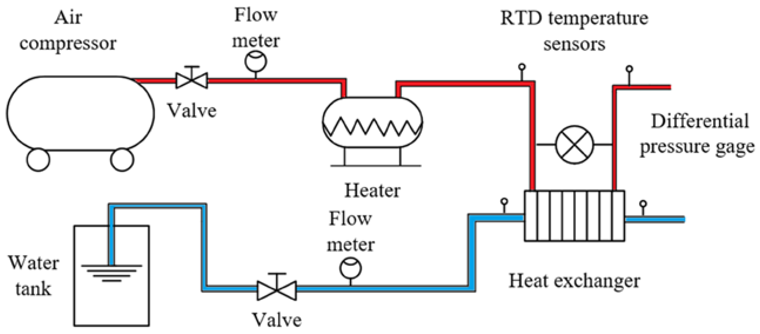
Figure 2.
A 3D-printed shell-and-tube heat exchanger: (a) photograph of the heat exchanger; (b) schematic of heat exchanger geometry; (c) tube bundle arrangement; (d) schematic of heat exchanger core; (e) geometry of octahedral lattice frame porous material.
Figure 2.
A 3D-printed shell-and-tube heat exchanger: (a) photograph of the heat exchanger; (b) schematic of heat exchanger geometry; (c) tube bundle arrangement; (d) schematic of heat exchanger core; (e) geometry of octahedral lattice frame porous material.

Figure 3.
Schematic of the grid system.
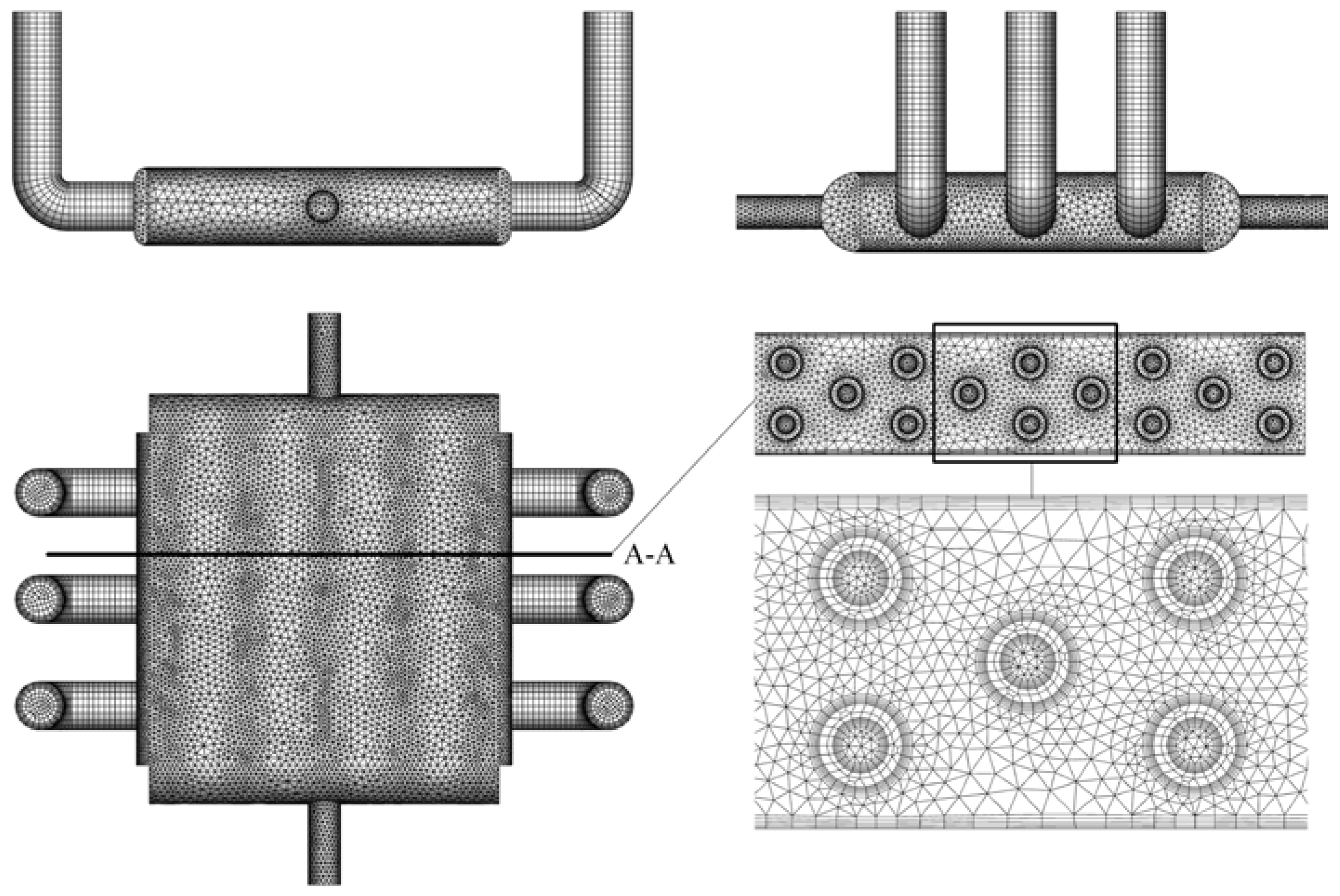
Figure 4.
Heat transfer process in heat exchanger.
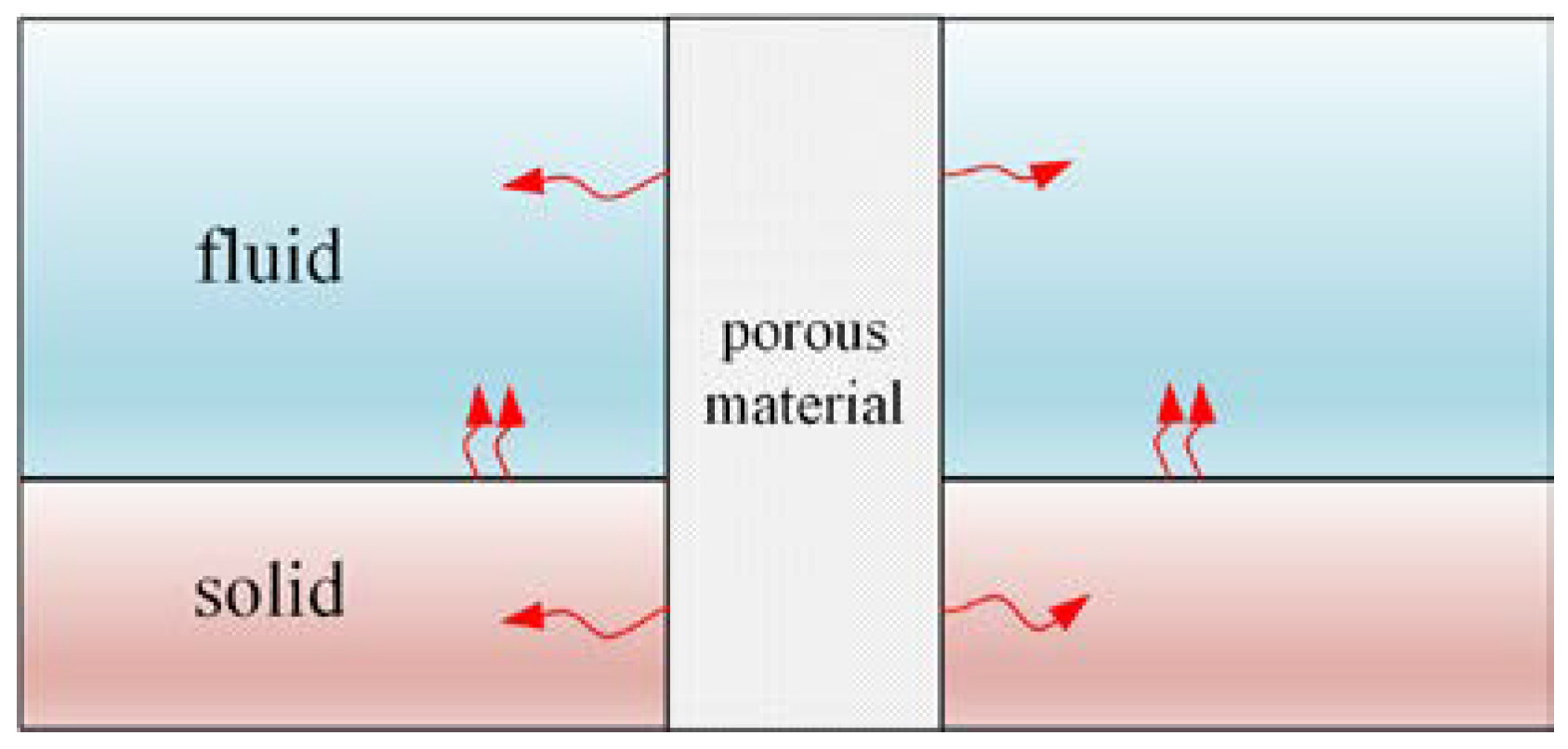
Figure 5.
Computational grids for obtaining fluid flow and heat transfer parameters.
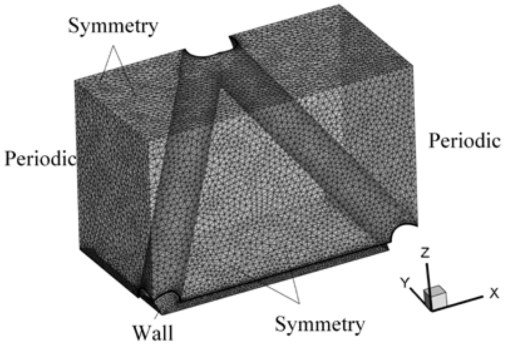
Figure 6.
Computation model for thermal conductivity.
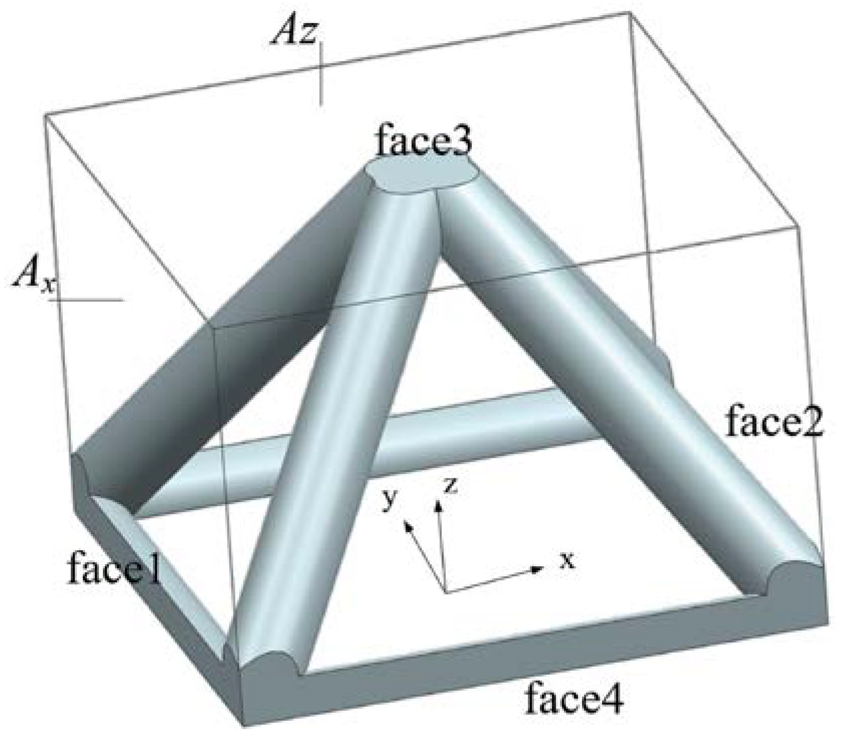
Figure 7.
Comparison between calculation and experimental results of pressure drop.
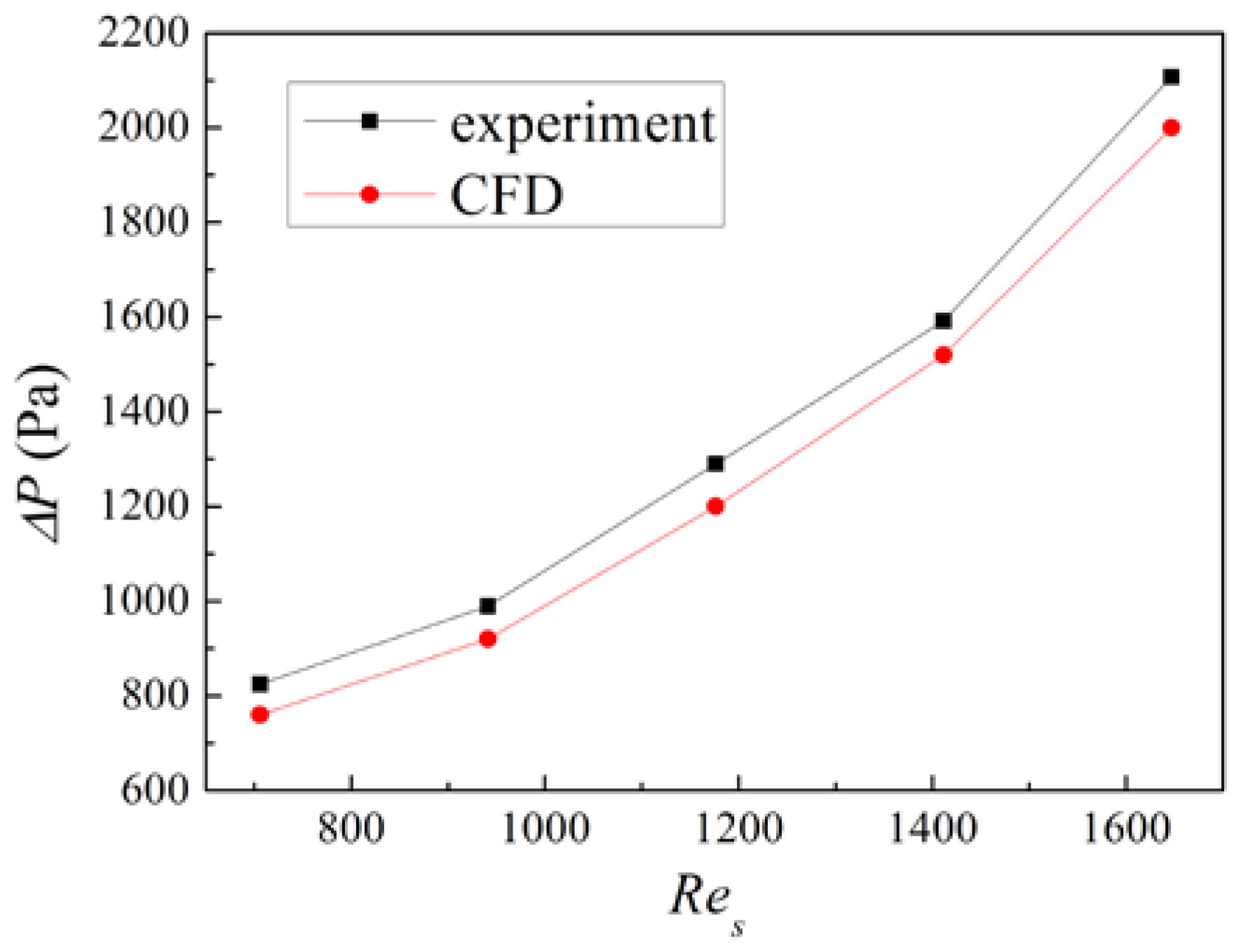
Figure 8.
Comparison of calculation and experimental results of heat transfer effectiveness.
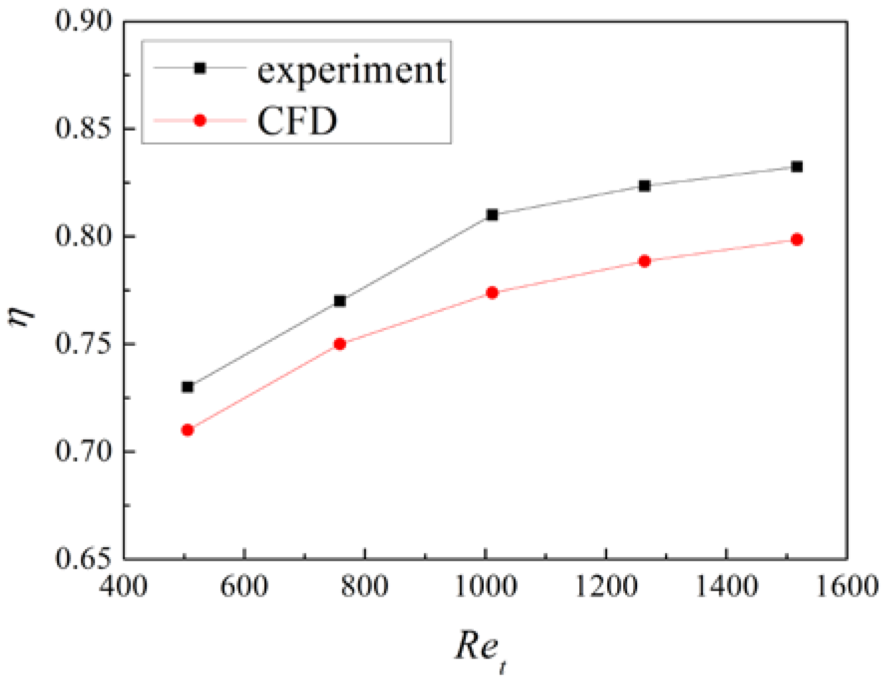
Figure 9.
Velocity field in the shell side of the heat exchanger.
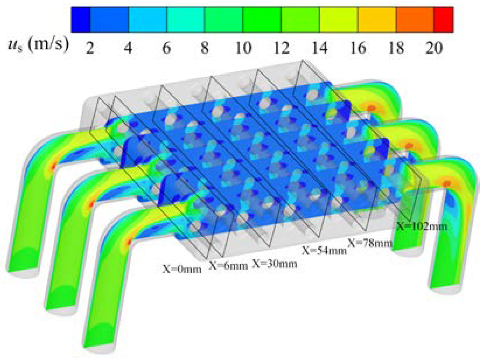
Figure 10.
Velocity distribution in the shell side of the heat exchanger: (a) x = 0 mm; (b) x = 6 mm; (c) x = 30 mm; (d) x = 54 mm; (e) x = 78 mm; (f) x = 102 mm.
Figure 10.
Velocity distribution in the shell side of the heat exchanger: (a) x = 0 mm; (b) x = 6 mm; (c) x = 30 mm; (d) x = 54 mm; (e) x = 78 mm; (f) x = 102 mm.
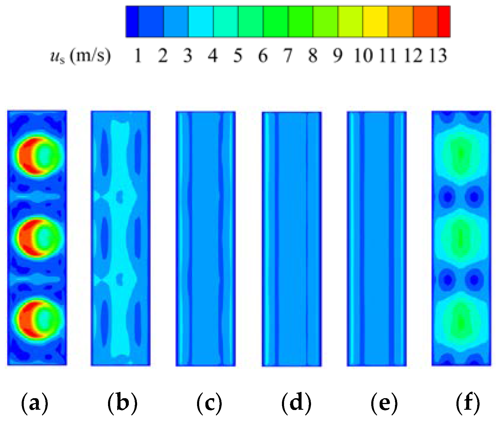
Figure 11.
Velocity field in the tube side of the heat exchanger.
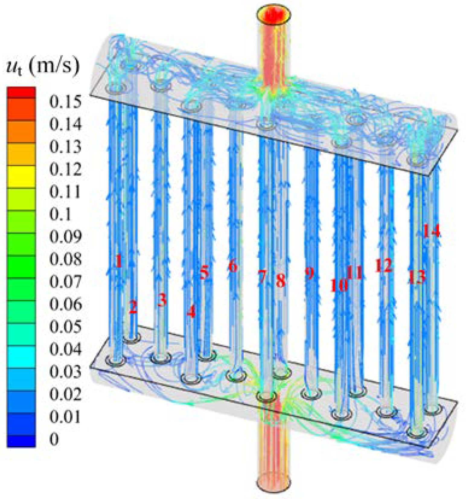
Figure 12.
Velocity distributions of the tube side.
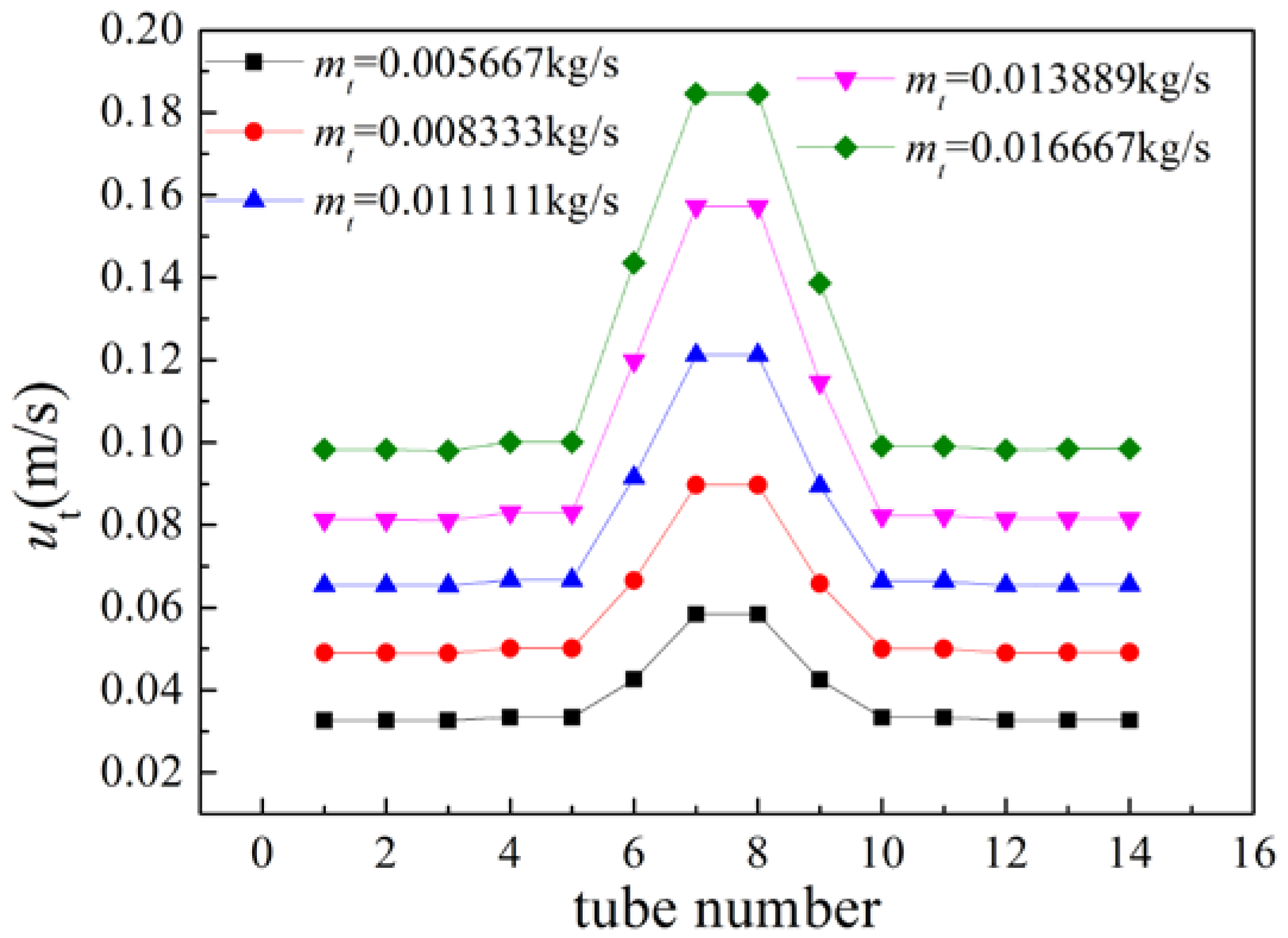
Figure 13.
Temperature distribution in the shell side (fluid phase): (a) x = 0 mm; (b) x = 6 mm; (c) x = 30 mm; (d) x = 54 mm; (e) x = 78 mm; (f) x = 102 mm.
Figure 13.
Temperature distribution in the shell side (fluid phase): (a) x = 0 mm; (b) x = 6 mm; (c) x = 30 mm; (d) x = 54 mm; (e) x = 78 mm; (f) x = 102 mm.
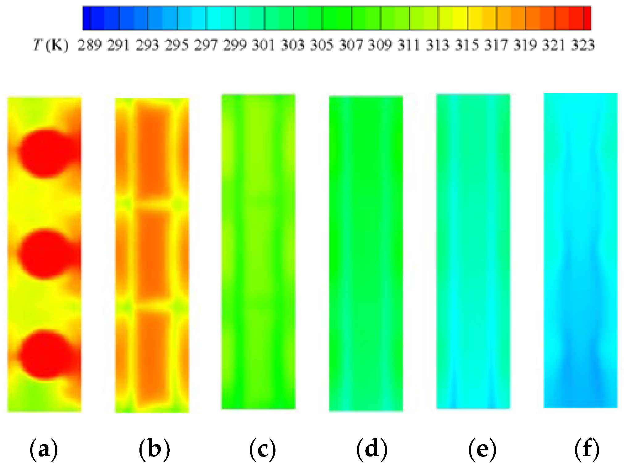
Figure 14.
Temperature distribution in the shell side (solid phase): (a) x = 0 mm; (b) x = 6 mm; (c) x = 30 mm; (d) x = 54 mm; (e) x = 78 mm; (f) x = 102 mm.
Figure 14.
Temperature distribution in the shell side (solid phase): (a) x = 0 mm; (b) x = 6 mm; (c) x = 30 mm; (d) x = 54 mm; (e) x = 78 mm; (f) x = 102 mm.
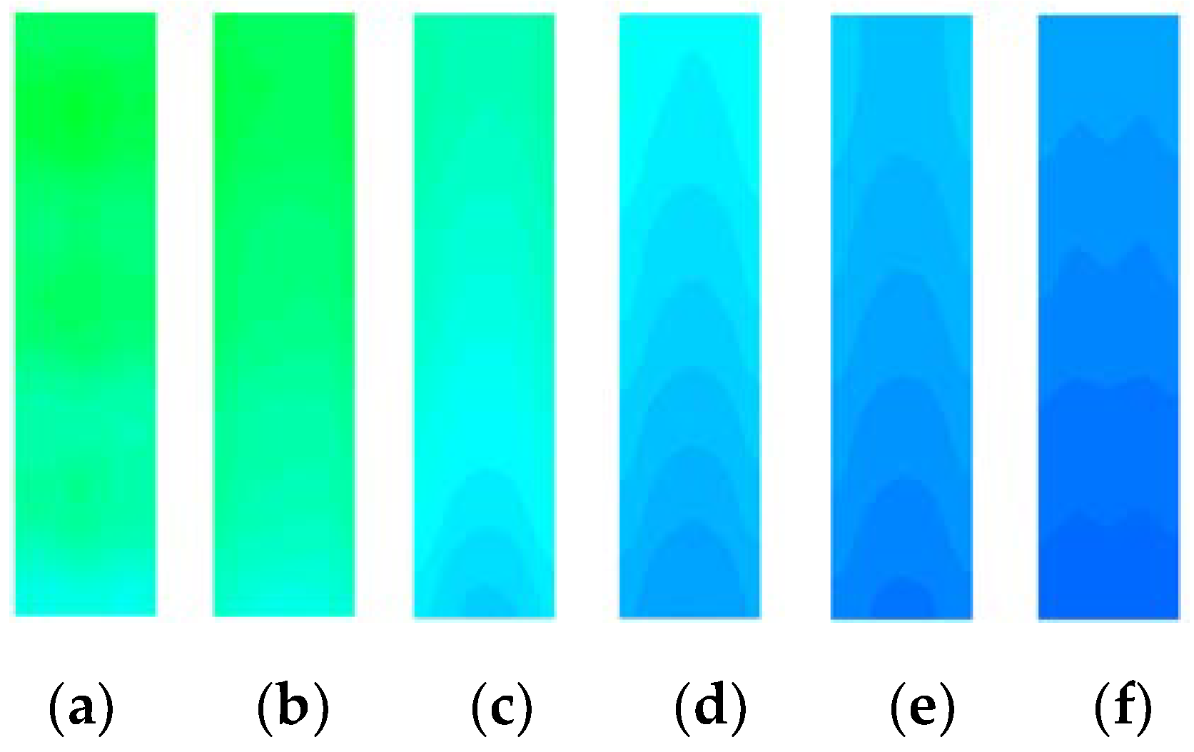
Figure 15.
Temperature fields in the heat exchanger under different mt: (a) mt = 0.00556 kg/s; (b) mt = 0.0111 kg/s; (c) mt = 0.0167 kg/s.
Figure 15.
Temperature fields in the heat exchanger under different mt: (a) mt = 0.00556 kg/s; (b) mt = 0.0111 kg/s; (c) mt = 0.0167 kg/s.
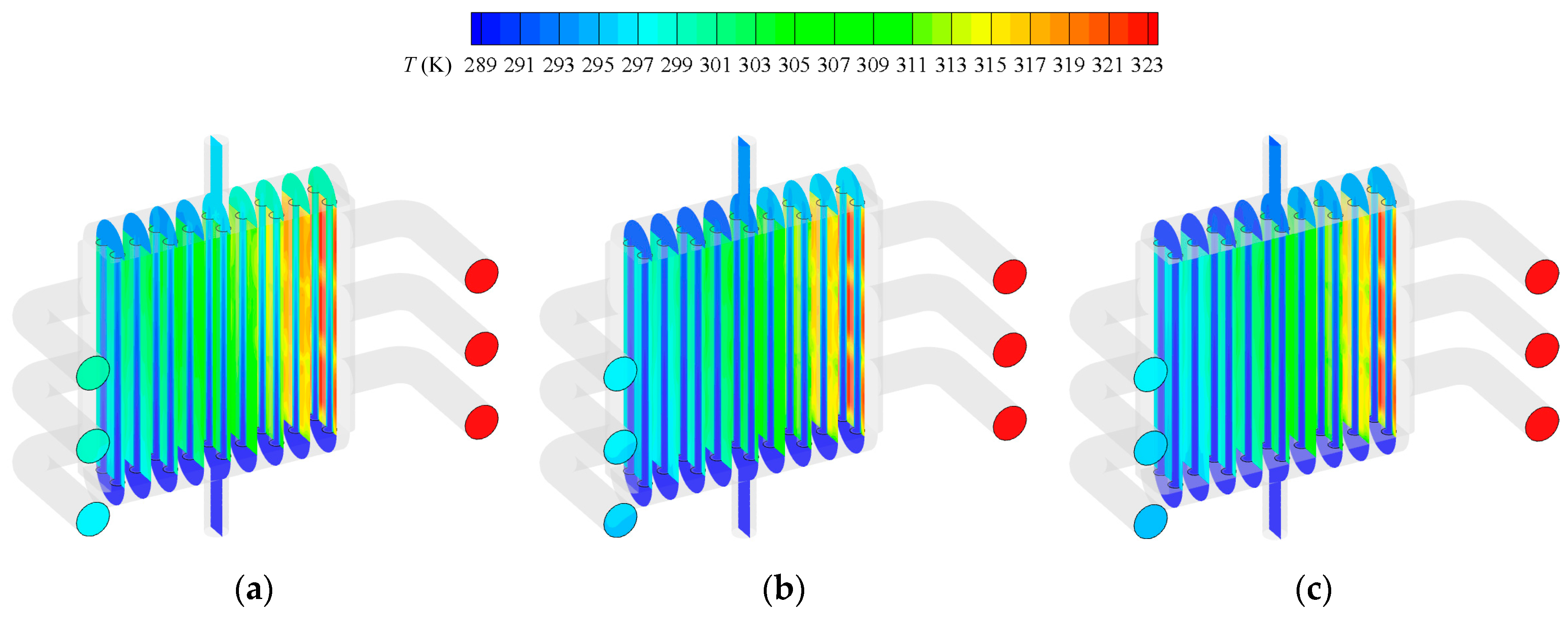
Figure 16.
Temperature increase of the tube side.
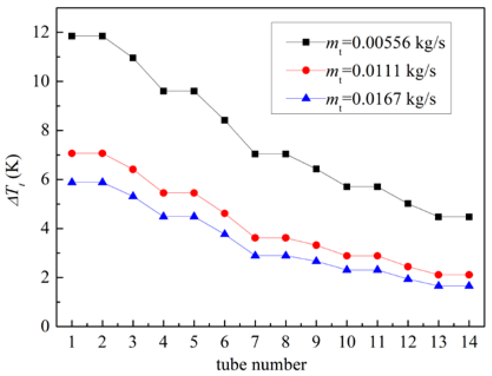
Figure 17.
Nusselt number of shell and tube sides.
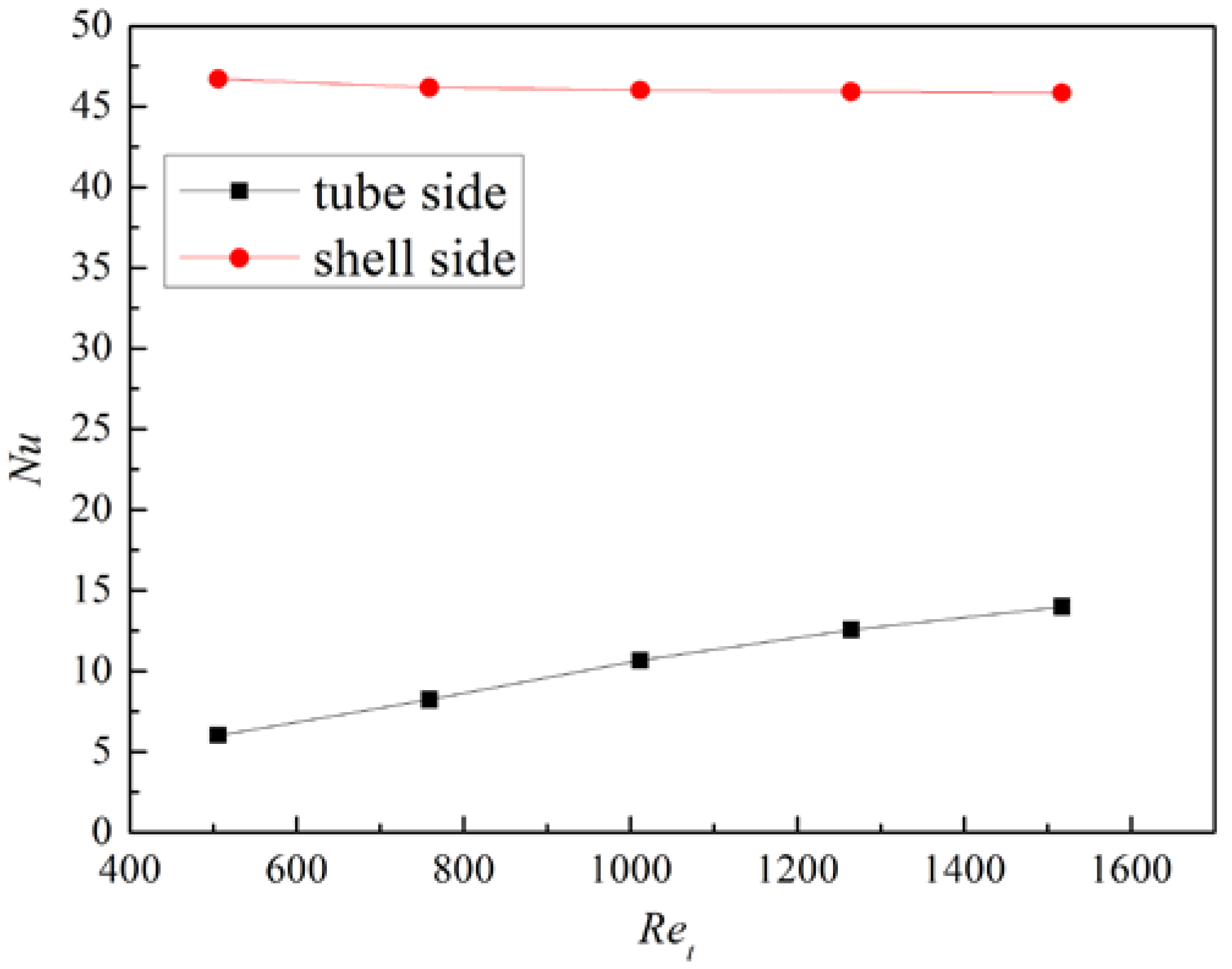
Figure 18.
Temperature fields of the tube and porous media under different mt: (a) mt = 0.00556 kg/s; (b) mt = 0.0111 kg/s; (c) mt = 0.0167 kg/s.
Figure 18.
Temperature fields of the tube and porous media under different mt: (a) mt = 0.00556 kg/s; (b) mt = 0.0111 kg/s; (c) mt = 0.0167 kg/s.

Figure 19.
Temperature distribution of solid tube wall.
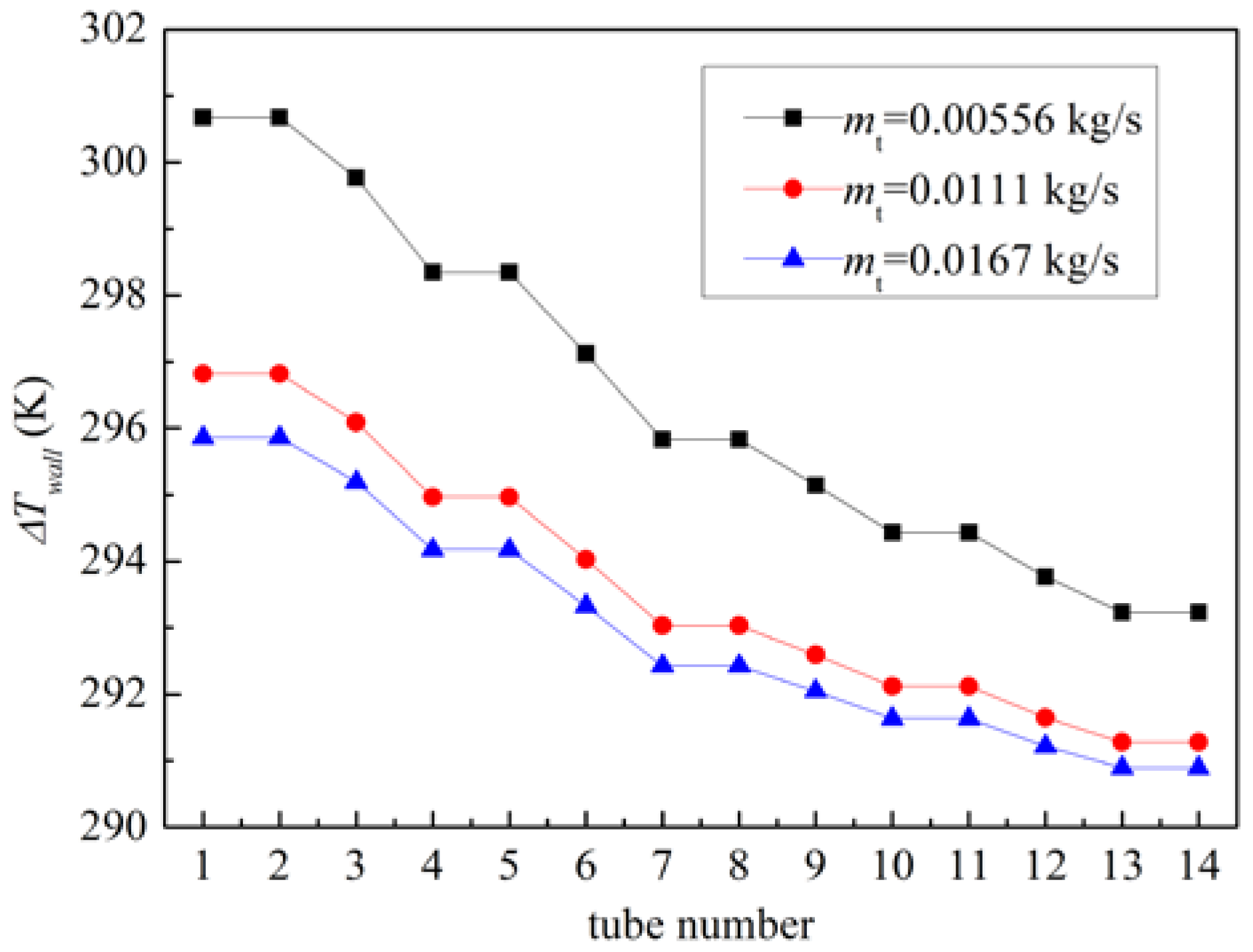
Figure 20.
Temperature decrease distribution of the shell-side air.

Table 1.
Boundary conditions for CFD simulations.
| Boundary Condition Type | Value | |
|---|---|---|
| Shell side walls | Adiabatic wall | none |
| Main tubes walls | ||
| Tube walls | Coupled wall | none |
| Water inlet | Mass flow inlet | 289 K, 0.00556 to 0.01667 kg/s |
| Air inlet | Mass flow inlet | 323 K, 0.00833 kg/s (hot condition) 293 K, 0.005 to 0.0116 kg/s (cold condition) |
| Water outlet | Pressure outlet | 101,325 Pa |
| Air outlet | Pressure outlet | 101,325 Pa |
Publisher’s Note: MDPI stays neutral with regard to jurisdictional claims in published maps and institutional affiliations. |
© 2022 by the authors. Licensee MDPI, Basel, Switzerland. This article is an open access article distributed under the terms and conditions of the Creative Commons Attribution (CC BY) license (https://creativecommons.org/licenses/by/4.0/).
Share and Cite
MDPI and ACS Style
Zhao, B.; Zhang, J.; Lian, W. Numerical Modeling of Heat Exchanger Filled with Octahedral Lattice Frame Porous Material. Aerospace 2022, 9, 238. https://doi.org/10.3390/aerospace9050238
AMA Style
Zhao B, Zhang J, Lian W. Numerical Modeling of Heat Exchanger Filled with Octahedral Lattice Frame Porous Material. Aerospace. 2022; 9(5):238. https://doi.org/10.3390/aerospace9050238
Chicago/Turabian StyleZhao, Bi, Jingzhou Zhang, and Wenlei Lian. 2022. "Numerical Modeling of Heat Exchanger Filled with Octahedral Lattice Frame Porous Material" Aerospace 9, no. 5: 238. https://doi.org/10.3390/aerospace9050238
Note that from the first issue of 2016, this journal uses article numbers instead of page numbers. See further details here.