1. Introduction
Increasingly, the world is becoming more dependent on electricity, directly and indirectly. Almost every sector in the globalized world has its process linked to the electric industry. In addition to the conventional use of electricity, an unreliable energy system negatively impacts sectors such as transportation, security, food, health, etc. [
1]. For this reason, outages are more than an inconvenience; they seriously threaten community safety, economic stability, and national security [
2]. Some factors can significantly impact an energy grid reliability, such as more frequent natural disasters, the current aged energy networks, the asynchrony between energy demand and supply, and the vulnerable energy control system [
3].
The rise in the severity and frequency of power outages due to extreme weather conditions has made studying grid resilience crucial. Furthermore, weather events are expected to become more severe due to climate change and global warming in the following years [
4]. Nowadays, several reliability indices are used to evaluate the power system performance, such as the System Average Interruption Duration Index (SAIDI), the System Average Interruption Frequency Index (SAIFI), and the Customer Average Interruption Index (CAIDI), among others [
5,
6]. However, these indices are not long enough to evaluate the whole system because they are focused only on high probability low impact disturbances, and the grid operates passively. They do not account for the primary power outages caused by extreme weather events; consequently, the recovery mechanism is limited to a specific point where the outage occurs [
7]. The entire grid reliability is only analyzed when a considerable and broad disruption happens. For that reason, new studies are needed to encompass the grid reliability to deal with both the impact caused by extreme weather and the fact that the current energy grid is aging and overdue for an upgrade [
8].
Additionally, with technological advances, smart grids are expected to spread in the following years, consequently resulting in intelligent homes. This scenario means that basically, everything in a house will need electricity, such as turning on or off the heating, cooling, doors, windows, everything, resulting in a society more connected and more dependent on electricity than ever [
9]. The same happens with businesses and other buildings that have their daily activity linked directly to electricity use. This interconnectedness means that every sector is negatively affected when part of the grid needs to be repaired [
10]. That is why it is important to design resilient energy systems; to prevent power disruptions or restore electricity quickly if an outage occurs [
11]. Additionally, the increase in advanced energy loads, such as smart appliances and electric vehicles, leads to another concern in the electric sector: the volatility and the asynchrony between demand and load, resulting in a struggle to provide a stable energy flow. In most cases, the utility grid needs to be oversized to supply peak demand, even for a short period [
12].
Research has shown that the way to improve the resiliency of the energy grid is to invest in microgrids integrated with renewable sources, especially by using a distributed system. Distributed generation has grown considerably all over the world, and this is basically due to the incentives for the use of renewable sources as the key to fighting climate change, as well as the advances in technologies and market expansion, which have increased the viability of the installation of small generators connected directly to the distribution network, as well as the advancement of new technologies and the need for the small power grid in remote places [
12]. To be considered a microgrid, a system needs to consist of an energy load and generators with a control capability, which means it can disconnect from the traditional grid and operate autonomously [
13]. In other words, a microgrid is generally connected to a utility grid; however, in the case of extreme weather and power outages, it can break off and operate on its own by using a local energy generation and, consequently, keep the load supplied.
According to the U.S. Department of Energy Microgrid Exchange Group, a microgrid can be defined as a group of interconnected loads and distributed energy resources within clearly defined electrical boundaries that act as a single controllable entity concerning the grid, which can be controlled as a grid-connected system or works in an off-grid mode. Different designs of microgrids are being developed to provide reliable energy using emissions-free sources integrated with energy storage systems, with a tendency to increase over time due to the falling cost of renewable energy sources associated with the efforts to replace fossil fuels and the frequent transmission line failures [
14].
A lot of research has been conducted regarding the possible scenarios and microgrid benefits. In [
15], the author states an overview of the integration of MEG with the existing utility grid and its main problems and points out the most relevant research, including distributed generation, applications with energy converters, management and control, protection, and communications. However, not much is found about the many challenges that must be dealt with. In [
16], the author summarizes different approaches and technologies that have been studied to address the complexity and challenges of microgrids, mainly regarding the power quality, which includes energy flow balancing, real-time management, frequency control, efficiency, and economical operation, as well as highlights the importance of focusing on fail-safe control and fault tolerance systems to improve the resiliency in advanced microgrids. In [
17], the paper identifies possible controller designs used in existing MEG, including the control system’s challenges, and proposes research systems with fault-tolerant control applied to a hierarchical architecture to enhance the smartness of control systems. More recently, many studies have focused on research and development in the area of fail-safe and resilience techniques for MG [
18,
19,
20]. Due to its multiple functions and many possible solutions proposed in the literature, the design of control systems for MEG is a complex engagement [
21].
Since microgrids are typically composed of different technologies and energy physics, power electronics converters are essential components that must be included in the MEG systems to integrate various energy networks, which consist of electronic devices able to convert electric energy from one form to another, such as alternating (AC) and direct current (DC), and also allowing the adjustment in energy voltage, current, and frequency [
22]. Additionally, power converters can be used to increase maneuver abilities in hybrid systems, especially with renewable sources, by controlling the extracted power in each source and stabilizing the energy flows between components [
23]. For these reasons, researchers are constantly exploring power converters technologies, and topologies to meet the more complex microgrid components integration [
24]; however, most of them have some limitations in adapting different energy flows and technologies.
In [
25] is presented a multi-input convert to be used in renewable energy applications; however, by using only a unidirectional power flow with limited components and a non-dispatchable current source. In [
26], the load can be supplied by different voltage levels prevenient from two sources without circulating current, using the multi-input converter, but it lacks modularity. The proposed converter in [
27] has fewer conduction losses, and the load supply can be performed individually or simultaneously from two different sources, which have different voltage–current characteristics with three power switches only; however, the proposed converter can be used only in DC microgrid applications, and the sources cannot transfer the power between them. For this paper, the proposed multi-input converter aims to work in bidirectional power flow capability and exchange the energy between the DC sources with minimum components parts. In addition, it has the modularity feature, so it can easily be adapted to different energy sources and consequently increase the microgrid reliability.
To develop reliable microgrids, it is crucial to focus on research and lab experiments and ensure that existing infrastructure adapts to new technologies. Lab experiments must simulate threats and responses and validate new technologies to help grid operators against outages. Performing experiments also help visualize the impact of climate change and the increasing of sophisticated cyber attackers to enhance the electric grid. One way to do this is by performing real-time simulations, which consists of testing computer modeling and small-scale energy system with real-life input and output. OPAL-RT Technologies is the leading developer of open real-time digital simulators and hardware in the loop testing equipment in the energy sector. OPAL-RT can be used to design, test, and optimize control and protection systems for power grids, power electronics, etc. In addition, the RT-LAB, core OPAL-RT software, enables users to develop models suitable for real-time simulation. RT-LAB models are fully integrated with MATLAB/Simulink [
28]. Simulink, developed by MathWorks, is data-flow graphical programming software for modeling, simulating, and analyzing dynamic systems. It supports simulation, automatic code generation, continuous tests, and verification of embedded systems. Integrated with MATLAB, it can incorporate MATLAB algorithms into models and export simulation results to MATLAB for further analysis [
29].
This paper aims to introduce an experimental platform for a micro energy grid with unique merits such as having sizable and extensible AC and DC loads, hybrid power and energy storage sources through real-time co-simulation, and a redundant control system for enabling the fail-safe and resilient control to the MEG. A sizeable load is considered the first merit and is developed through an array of relays to dynamically change the arrangement of series and parallel connections between loads to determine the designated load value, which is applicable for AC and DC loads, including capacitive, inductive, and resistive load types. The second merit is combining a real-time simulation to emulate power and energy sources that are impracticable to be considered in lab sizes, e.g., wind turbines as a power source and flywheels as energy storage. The real-time simulation is designed based on OPAL-RT simulator OP4510 to connect the real-time hardware signals with the Simulink models. The signals that could be manipulated and connected are input signals from sensors and switches, while output signals like relaying simulation output signals are used to activate and run actuators, e.g., motors. The third merit is the redundant control system which utilizes two controllers: the first is based on a microcontroller array, and the second is based on a PLC controller aiming to back up each other and maintain the system availability.
The paper is outlined starting with the introduction section, followed by
Section 2 presenting the design and co-simulation of the microgrid, and introduces the proposed microgrid’s design and structure, highlighting the proposed system innovation.
Section 3 demonstrates the testing and validation.
Section 4 shows the resiliency, fail-safe control, and fault-tolerant capacity of the proposed microgrid. Finally,
Section 5 concludes the work.
2. Design and Co-Simulation of Microgrid
The MEG consists of three main components: power sources, controllers, and energy loads. Therefore, it is possible to develop hybrid energy systems by combing different components technologies with hardware and emulators subsystems. The main features of the microgrid proposed in this paper consist of:
Resiliency technique based on redundant control between microcontroller and PLCs;
Hybrid energy sources, i.e., PV, utility grid, and energy storage system (battery bank);
Programmable DC load and AC load based on relay control and load management;
Hybrid power bus topologies, i.e., DC and AC networks;
Master–slave networking topology between master and slave PLCs (1211C and 1214C CPUs).
The system schematic proposed in this paper consists of a microgrid with an interconnected power system, including physical sources, such as the utility grid and a solar panel, and emulated power sources, such as a wind turbine, using a real-time simulator. In addition, the system includes energy storage systems, physically and simulated, such as battery bank and flywheel, respectively. Furthermore, the system has a redundant control system based on microcontrollers and PLCs, as well as a dynamic load system, which consists of an AC and DC relay controlled sizable load. The following subsections elaborate on the system structure, including system components and parameters and the co-simulator based on Opal-RT OP4510.
2.1. Microgrid Structure and Resources
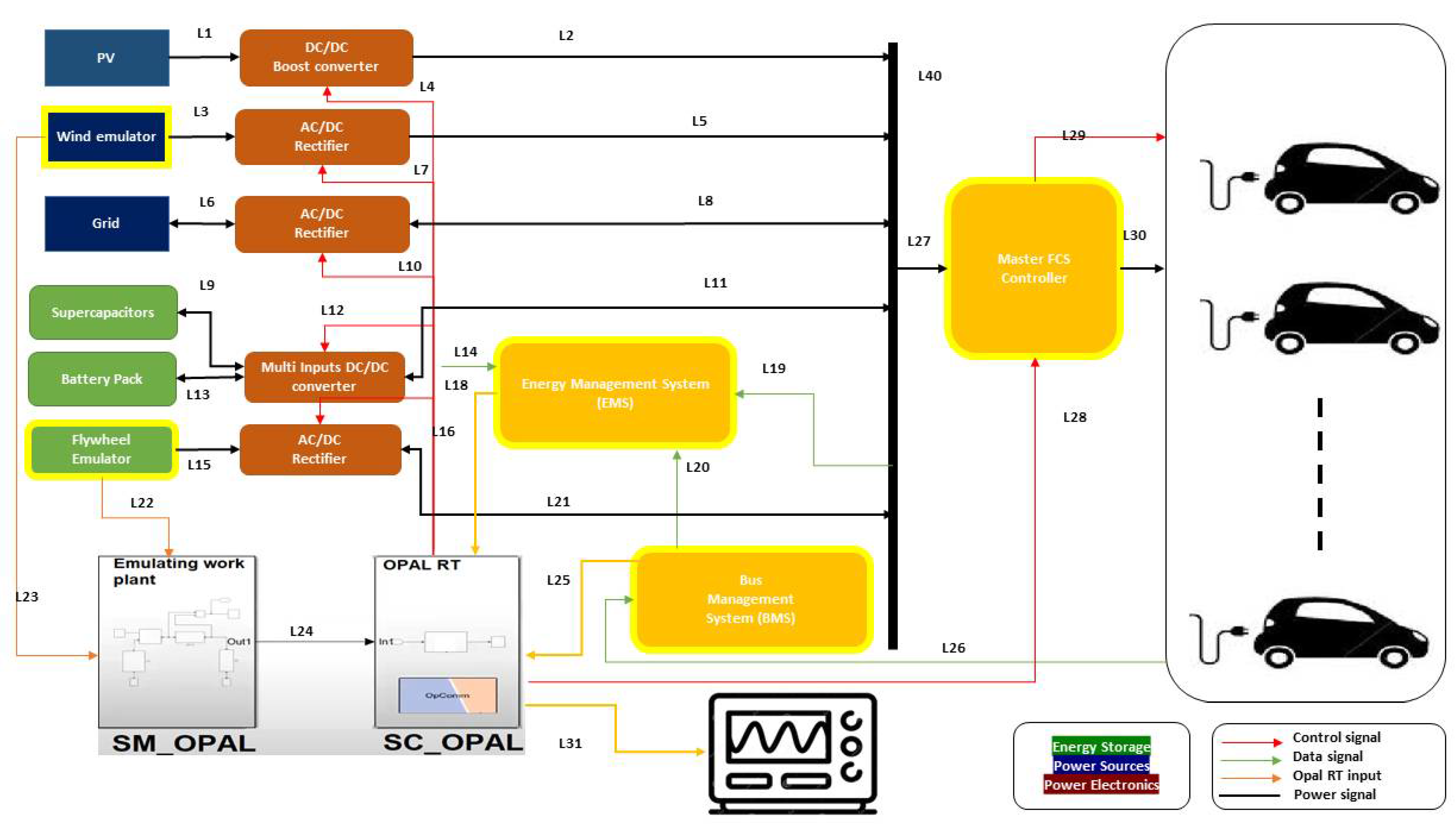
The structure of the proposed microgrid is shown in
Figure 1. The system consists of AC and DC load, controllers, and power sources, including PV panels, emulated wind turbines, and flywheels based on real-time simulation, battery bank, and supercapacitors. Due to the complexity of using actual wind turbine and flywheel systems on a small scale for laboratory purposes, both approaches are emulated by using real-time simulations, which mimic the actual behavior of these technologies. The wind turbine and flywheel emulators using MATLAB/Simulink and testing using an OPAL-RT real-time simulator.
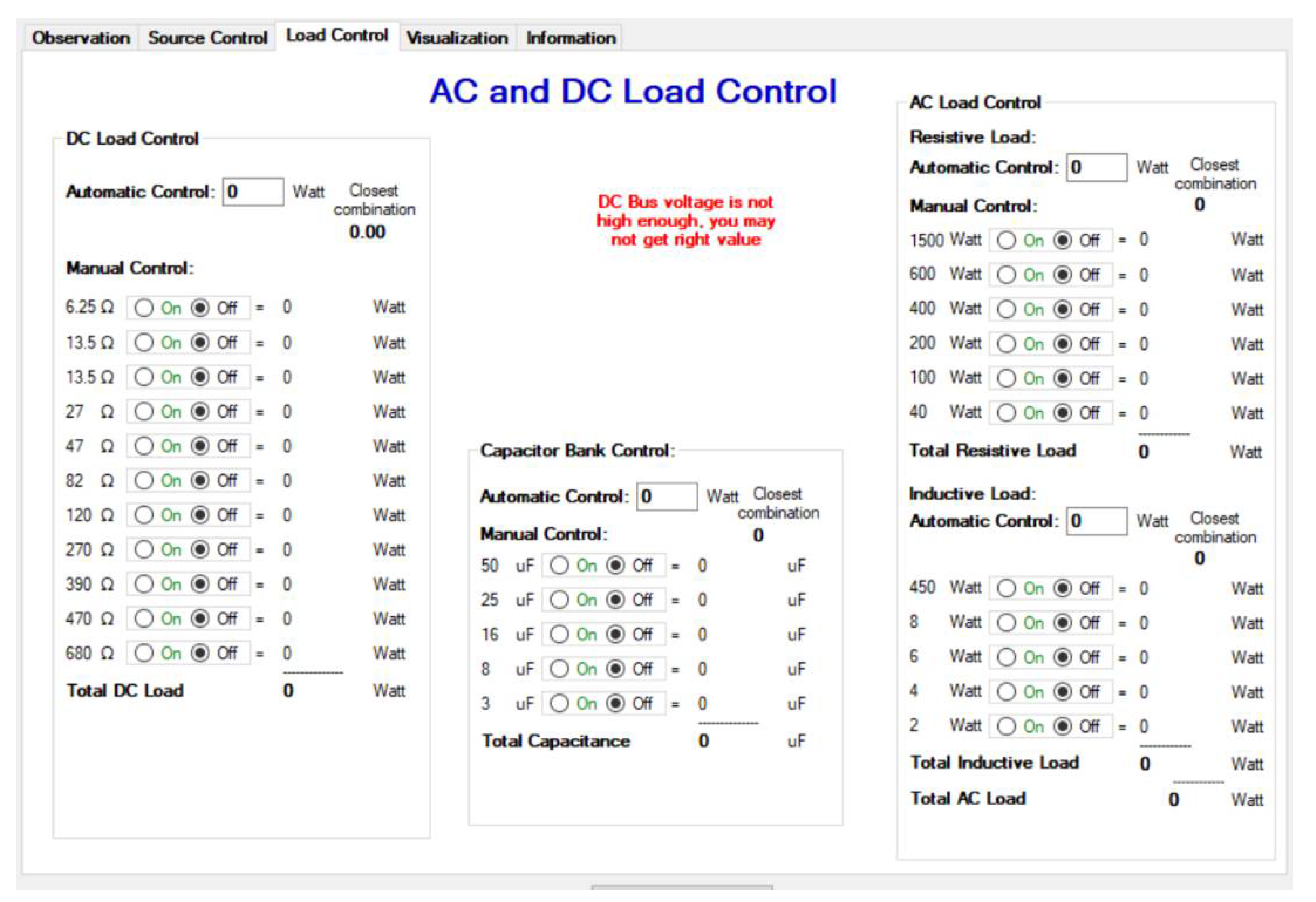
Regarding the energy loads, the system includes AC and DC programmable loads by changing the series and parallel arrangement of the loads using a bank of relays controlled by microcontroller-based relay drivers. In addition, the controller can insert or withdraw some loads based on the system capacity limit or according to the user’s request.
Figure 1 shows two types of power sources: physical power sources such as PV and the utility grid are highlighted in dark solid blue and emulated power sources such as wind emulators are highlighted in dark blue with a yellow border. Additionally, it shows two types of energy sources: physical energy sources such as supercapacitor and battery pack are highlighted in green and emulated energy sources such as emulated flywheel are highlighted in green and yellow border. The figure shows the bus and energy management controllers in the middle. In addition, the co-simulation based on OPAL-RT (OP4510) is connected between the hardware and simulation Simulink for cooperating between the emulated components, called emulated plant, e.g., flywheel or wind turbine, and the hardware components of the systems.
Table 1 lists the system components describing their types and parameters, stating the physical and emulated power sources, energy storage, AC and DC loads, converter, inverter, and real-time simulator. It shows each component’s capacity and limits, voltage, input, and output parameters.
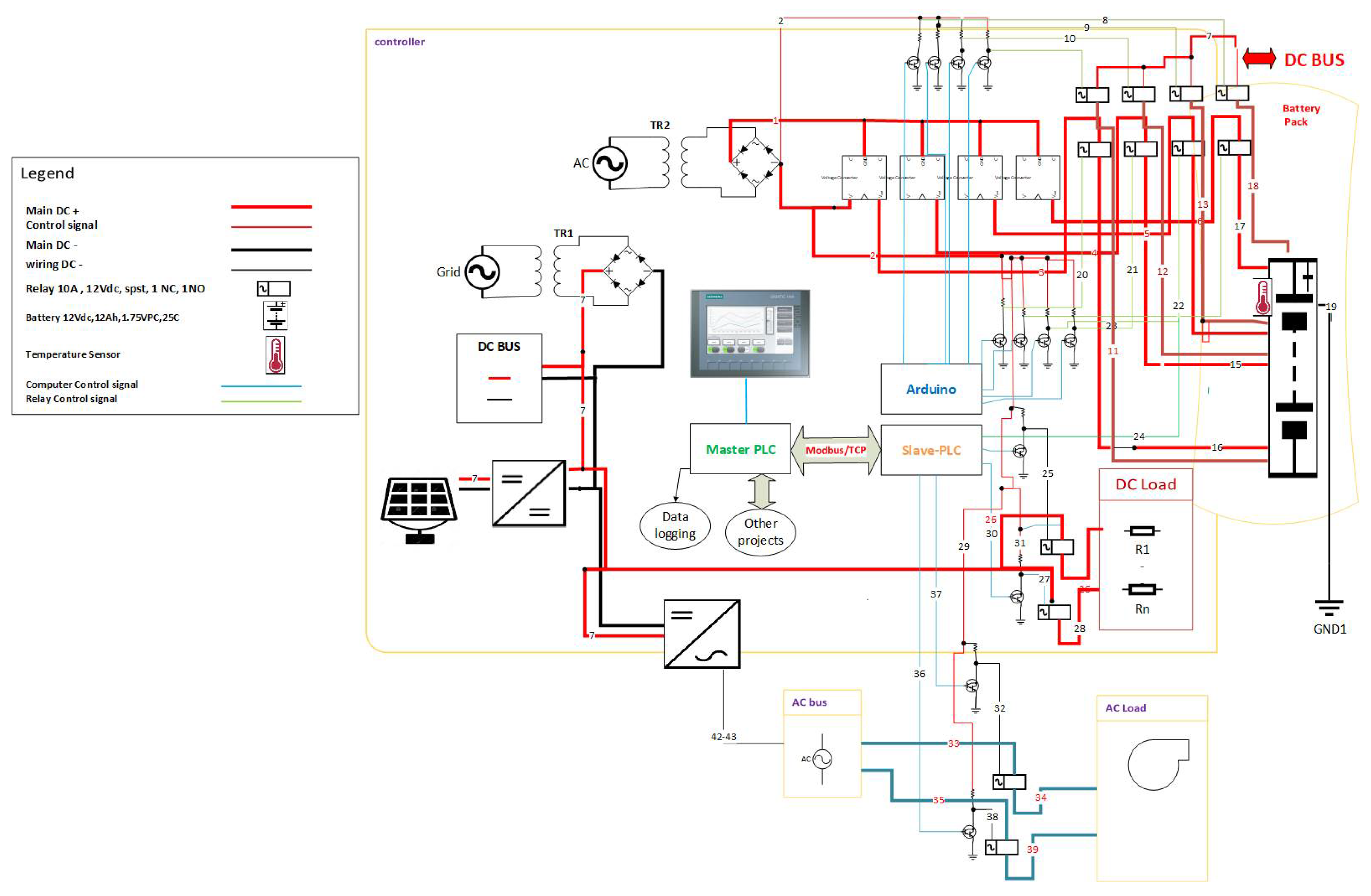
2.2. Circuit Design
Figure 2 depicts the schematic of the MEG circuitry, including relay array and microcontrollers, PLCs, inverter, converter interfaces, and dynamic loads. Since the system has been designed in the lab and consists of modular sectors, i.e., controlling units, signal acquisition boards, inverter, and power converter circuits, it makes easy maintenance and upgrading flexibility possible. Regarding the schematic details, the system consists of relay driver boards for driving the variable DC and AC loads, a variable capacitor for power factor correction, a charging controller of the battery pack, sensor boards for adapting the sensors’ readings with the acceptable limits of microcontrollers, Arduino boards, communication devices for TCP ethernet connections, Modbus connectivity, pure sine wave inverter, bidirectional and multi-input power converter, and the PLC controllers in master-to-slave topology. Additionally, the system provides hybrid AC and DC bus systems that can feed different loads.
2.3. Fail-Safe and Resiliency Design of Microgrid
The concept of a resilient, intelligent, and effective microgrid brings forth promising enhancements for the current energy scenario without the necessity of redesigning the existed transmission lines, increasing the ability to integrate different types of energy demand with advanced energy storage systems, and with a high share of distributed power generation from renewable energy sources. However, as the diversity of distributed generators and energy load increases, the complexity of operating, controlling, and monitoring all the nodes within the system to maintain the power flow stability increases. Therefore, in addition to a myriad of benefits that a theoretical MEG can provide, there are some challenges that an effective energy management system needs to bear to become reliable [
30].
2.3.1. Fail-Safe Algorithm
An essential factor that impacts the power quality is the ability to smoothly switch between energy sources and controllable loads that become undetectable for emergency loads. The necessity to change between the energy source surge for different reasons, mainly due to problems on the transmission side, such as climate destruction or utility grid maintenance, resulting in the necessity of switching between the grid-tied and islanded mode. This transition needs to be smooth enough to avoid or cause a less possible interruption in the energy supply. When it is necessary to change to an island mode, the energy management needs to identify a better scenario to meet the energy demands, activating the energy storage system and auxiliary generators.
This mechanism is commonly performed by using electric actuates, which require a constant energy source to operate and that can identify power loss in the system and drive actuators to a predetermined safe position to maintain the energy supply for the system [
31,
32].
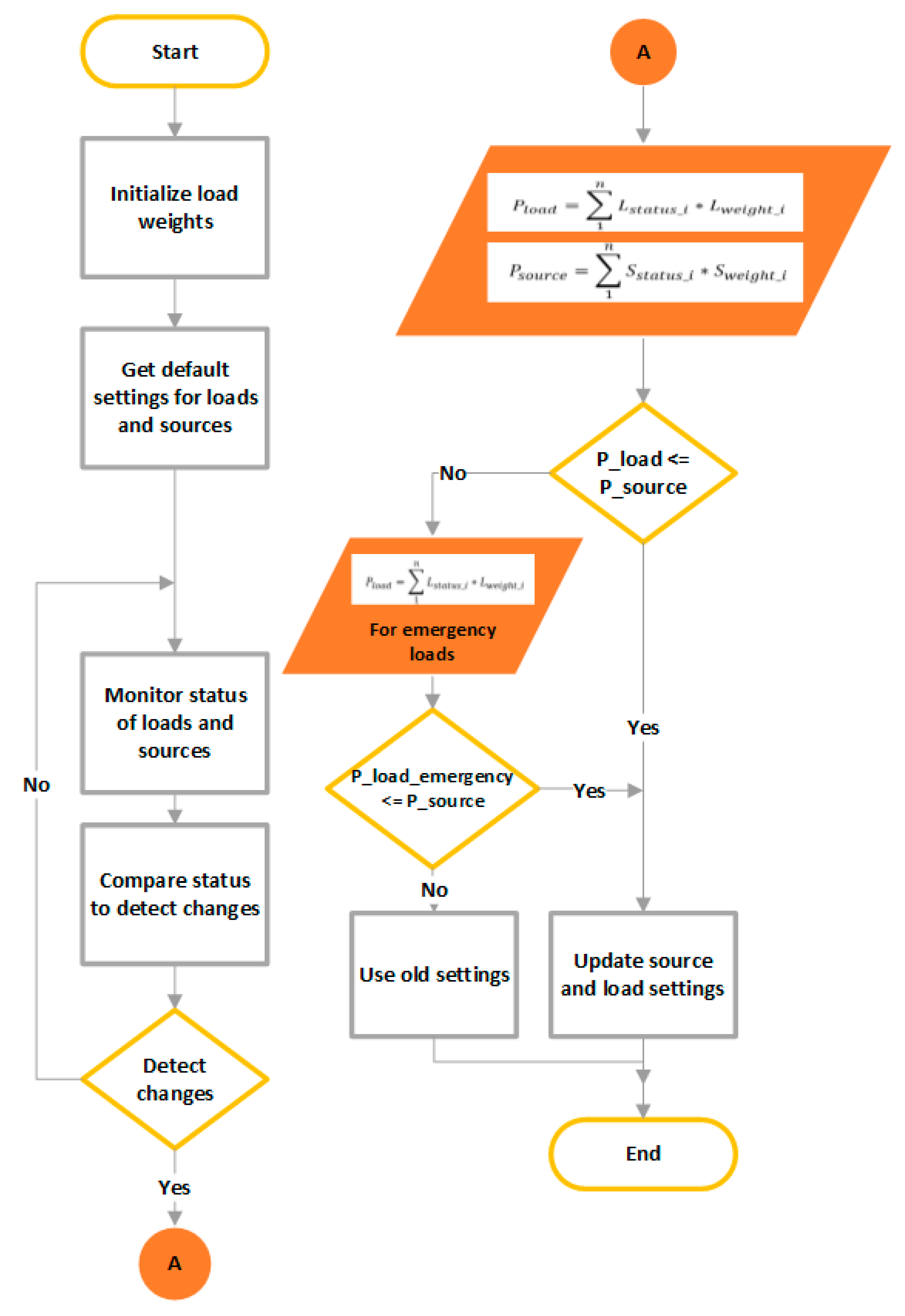
Figure 3 charts the logic flow of the fail-safe algorithm that guarantees the balance between load demand and available power source capacity by monitoring the status of loads and sources. It calls for a fail-safe routine to detect a change in any contact’s position by calculating the load demand and source capacity smartly based on current statuses and checking the power availability to fulfil the request load demand. If there is plenty of power to satisfy the loads, it updates the system accordingly. However, if there is a power shortage, it calculates for emergence loads. Then, if the amount of available power sources can satisfy the emergency loads, it activates the emergency loads only. Or, it loads the previous safe settings of loads and sources.
2.3.2. The Resiliency of the Microgrid
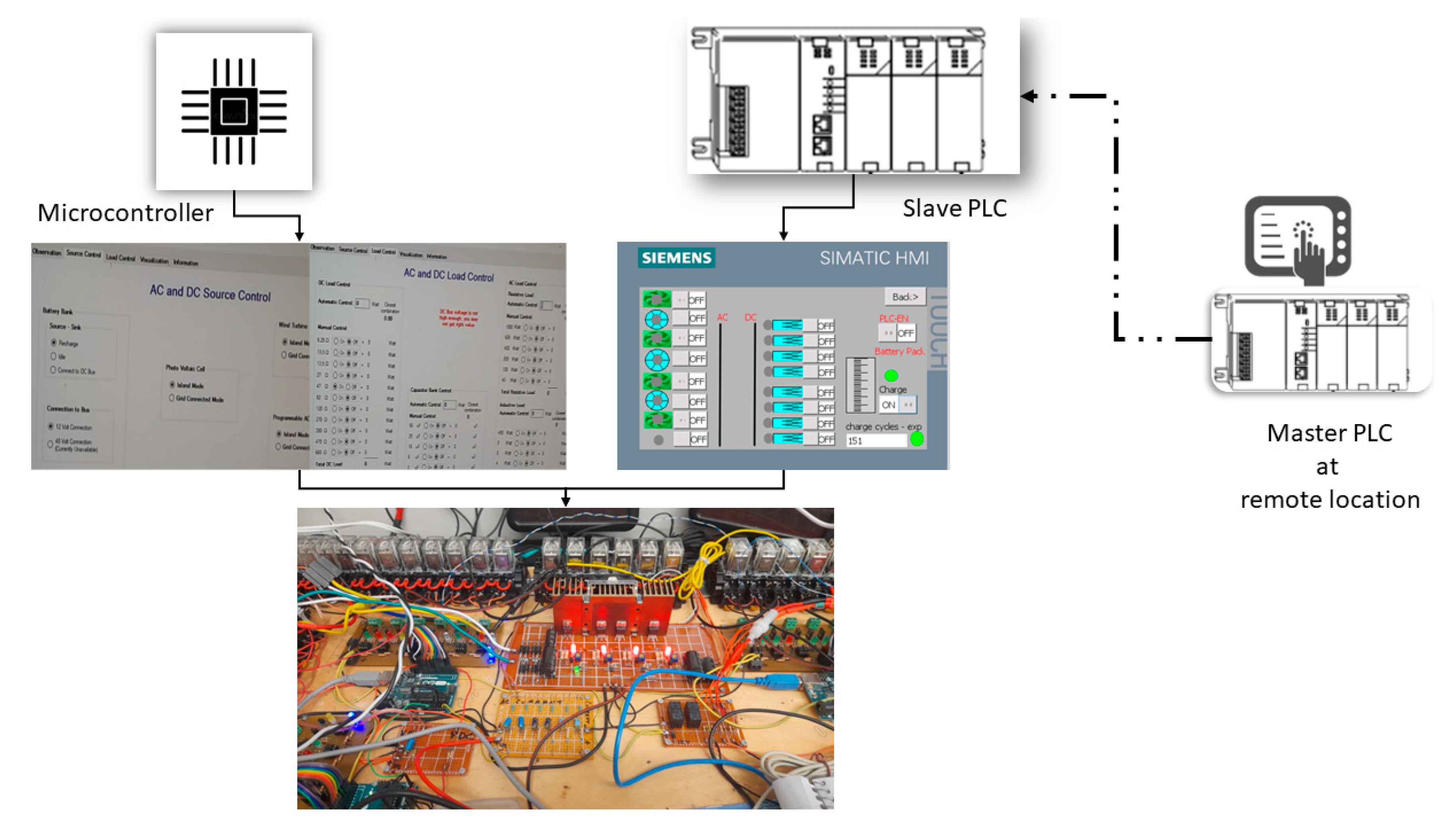
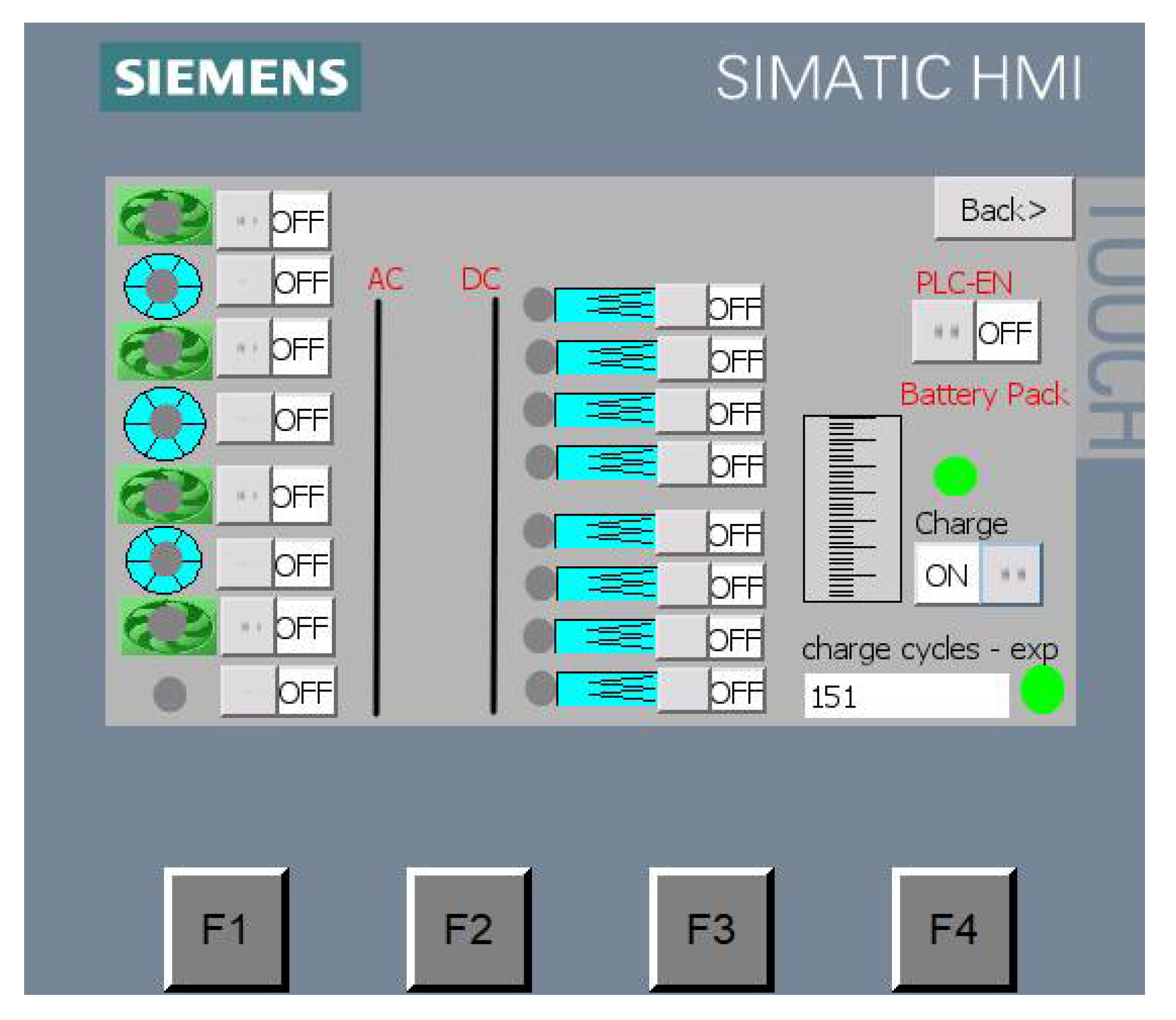
Figure 4 demonstrates the resilient design of the microgrid by showing the remote access ability to monitor, control, and perform maintenance to the microgrid by using the modbus-based communication between two PLC controllers. This way, the microgrid can be accessed from anywhere without having operators on site. In addition, the redundant control topology between PLC and microcontrollers maintains the microgrid secured when one controller goes down. Thanks to the firm and safe control algorithm, the microgrid can simultaneously be commanded from both sides.
2.4. Fault-Tolerant Control of Microgrid
The concept of fault-tolerant power systems consists of a technique in which the energy system can ensure continuous and uninterrupted functionality. One of the requirements for a resilient system is to avoid outages. The system must be immune to single or multiple failures in the primary energy supply, which is made by developing architectures with backup and redundancy power sources.
Fault-tolerant control can be classified into active management and passive control. Passive control is widely used due to its robustness. Prior knowledge of possible faults is required for such control that may alter the system’s stability. Due to those faults, the elements installed, such as consumers and subsystem components, might affect their fundamental performance. Therefore, fault tolerance is required to provide the continuity of the microgrid functionality, and the following techniques can achieve it:
Fault detection: it consists of the appearance and detection of possible faults within the microgrid system.
Recovery: it means the replacement of the fault states with a particular state. It consists of two mechanisms:
- ∘
Fault management: fault state needs to be eliminated to clear the erroneous state of the microgrid.
- ∘
Fault handling: diagnosis, isolation, reconfiguration, and reset are required to resolve the fault.
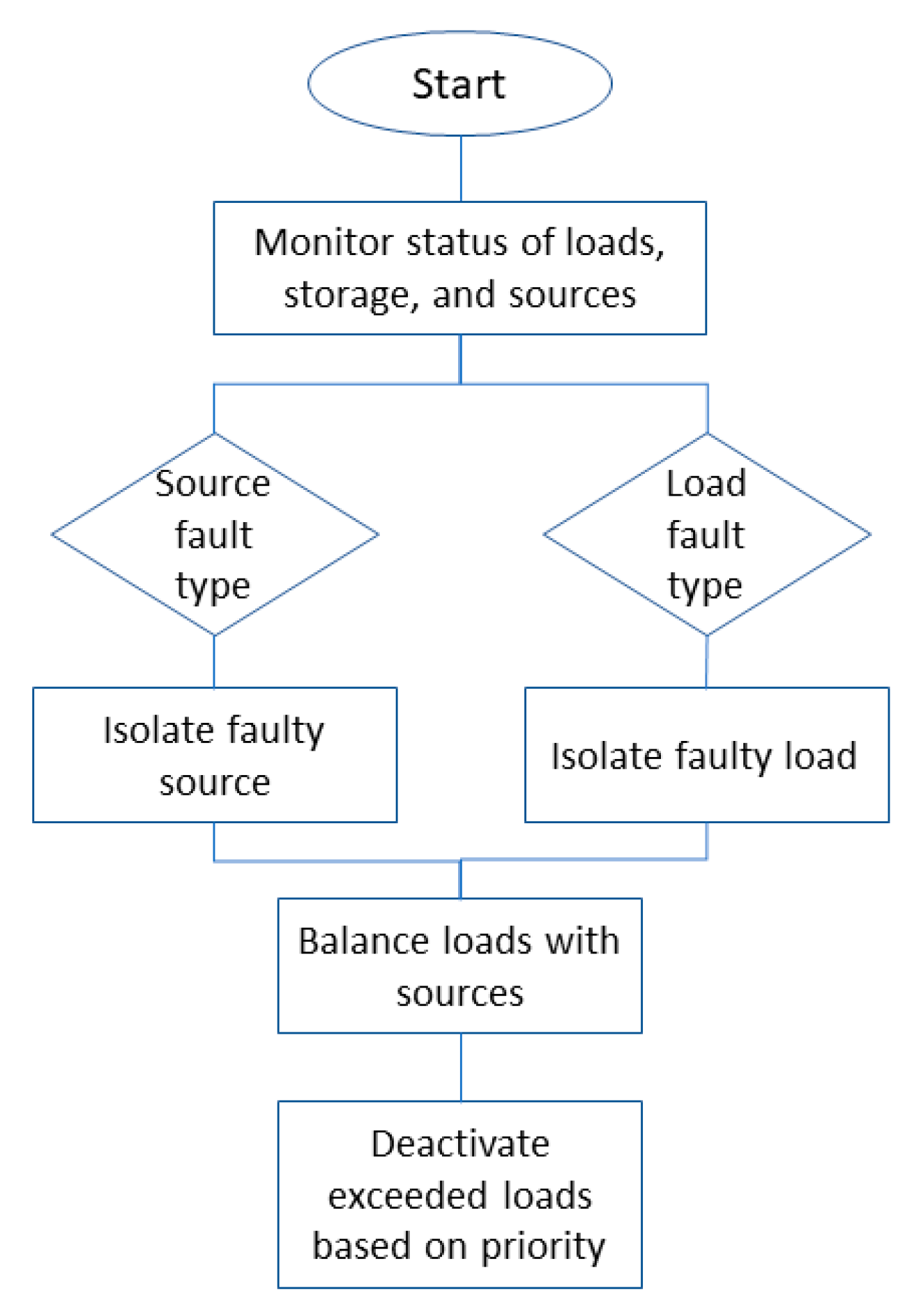
This experimental work, stated in
Figure 5, uses a fault tolerance algorithm based on PLC and relays logic control. PLC scans the loads, power sources, and energy storage statuses by reading the relays contacts statuses. Then, it checks the type of faults; if it is related to load, it isolates the faulty load(s), but if it is related to source(s), it isolates that source. Then, it calculates balanced load demands and power source generation. Ultimately, it activates and deactivates load(s) accordingly. In other words, it carries out a corrective action based on balancing the demanded load with the available power after isolating the faulty source(s) and or load. The main features of the proposed control are:
Regulating microgrid voltages considering faults within the supplies and loads.
The control strategy is robust against those faults, disturbances, and harmonics as changing the controller structure is not required like the existing controller. Therefore, even when some part of the system fails due to fault conditions, the proposed controller enables the continuity of the safe operation of the microgrid and thus increases the system’s reliability.
Finally, two case scenarios have been designed, the controller has been implemented in hardware to demonstrate its performance, and the results are described.
2.5. Microgrid Control
The redundant control technique has been designed based on three microcontrollers and two PLC controllers connected based on master-to-slave topology.
Figure 6 shows the design of the microgrid control system that has been driven redundantly by microcontrollers and PLC, meaning when one controller is down, the other takes over the control to increase the reliability of the MEG. In addition, the system may receive commands from any of them to maintain a fail-safe system. Additionally, by applying master-to-slave control, one PLC works as a master controller (remote) that can send commands to the slave controller (local) to enable remote access to the system from anywhere. In addition to the remote access, the system can monitor all metrics, faults, and measurements of the system that can be used in analysis work for concluding and forecasting purposes. The figure also shows the interconnected system components, including the connection between the master PLC and slave PLC and the HMI screen connected to the master controller as a user interface to the control system. In addition, it shows the ethernet communication based on eight ports ethernet switch and how the two ways controllers, Arduino-based and PLC-based controllers can share the responsibility of controlling loads.
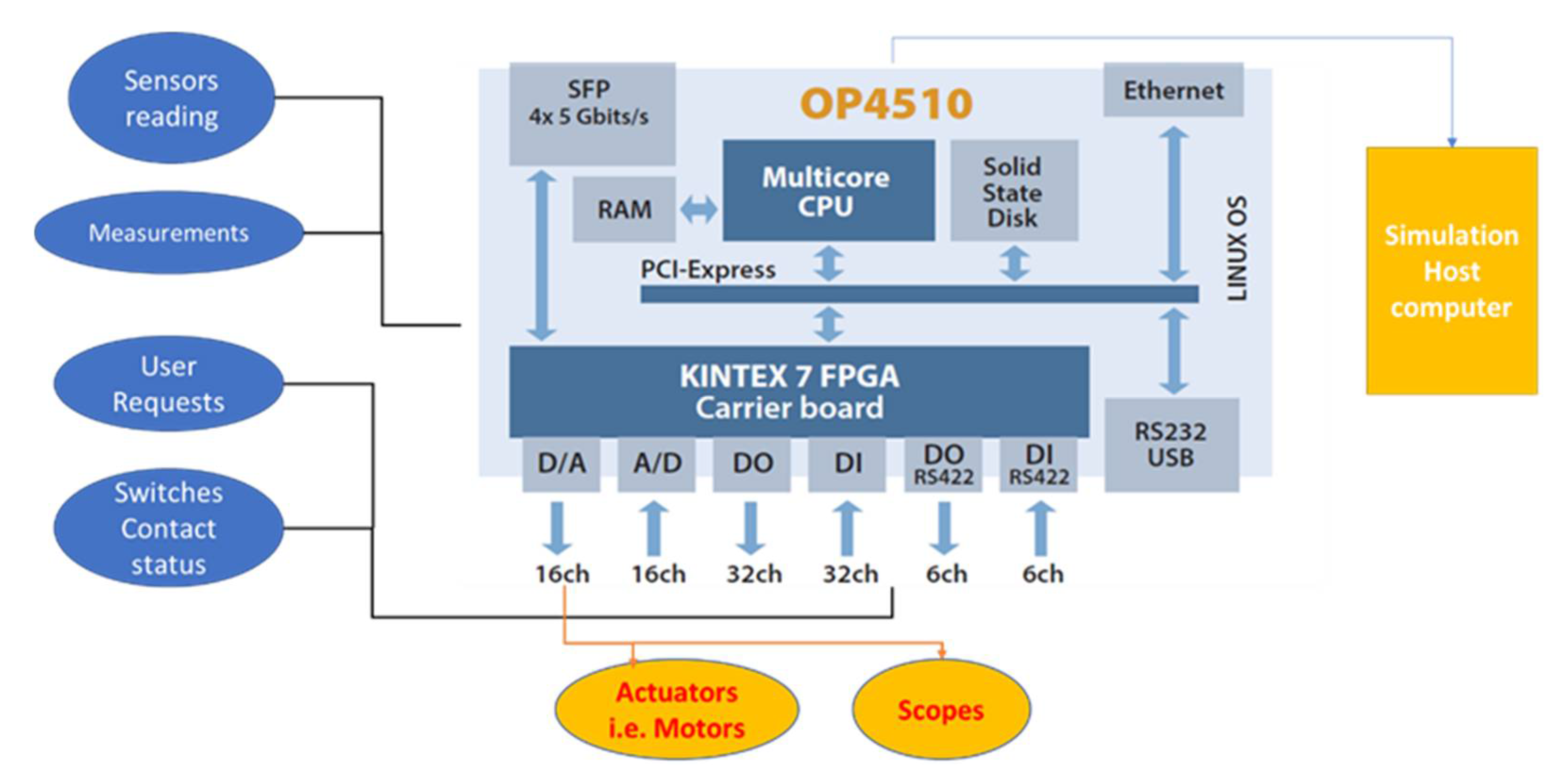
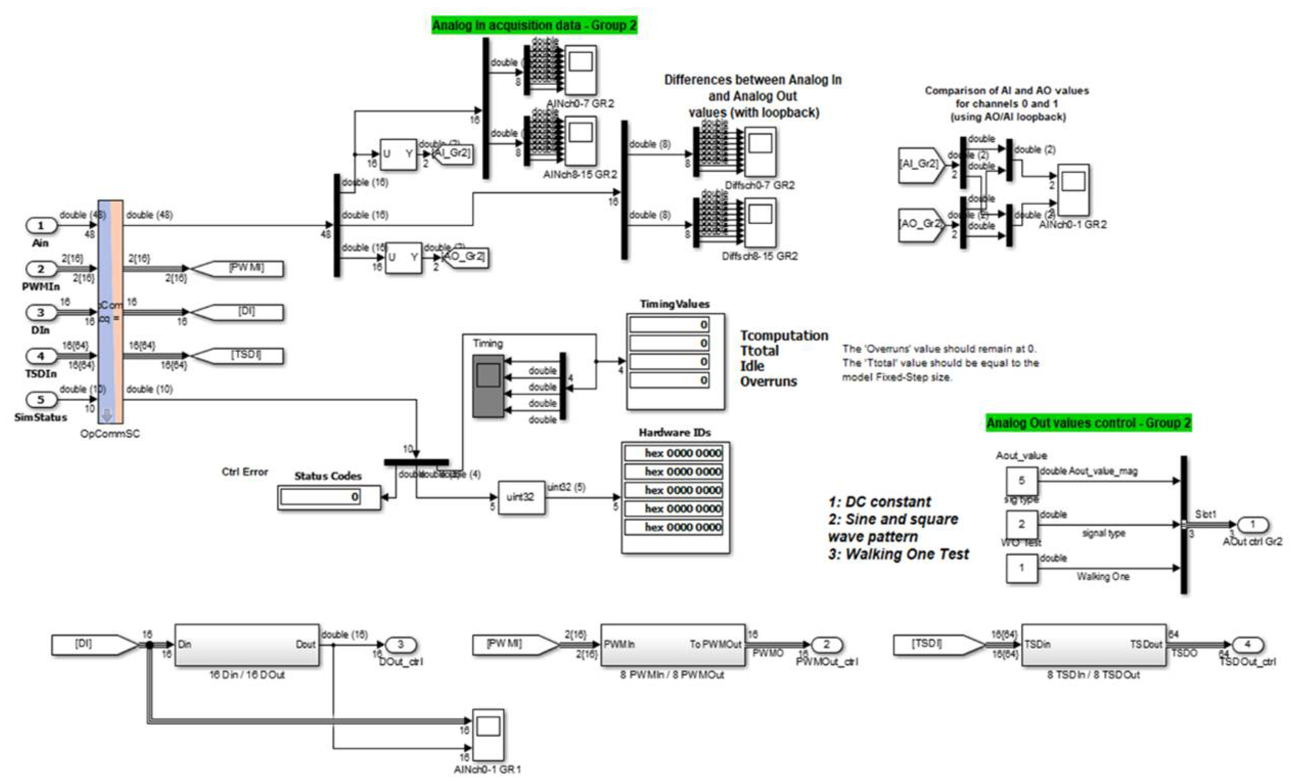
2.6. Co-Simulation Based on OPAL-RT
Real-time simulation is a technique used to mimic and analyze the system performance at the same rate as the actual physical system using computer modelling. Real-time simulations are used widely in several engineering fields and can be configured in hardware-in-the-loop simulations by testing controllers using real-life conditions.
OPAL-RT Technologies is the leading developer of open real-time digital simulators and hardware in the loop testing equipment in the energy sector.
Figure 7 depicts the outstanding features of OPAL-RT (Model OP4510), which include 32 channels of digital inputs (DIs), 32 channels of digital outputs (DOs), and 16 channels of analog inputs (AIs), and 16 channels of analog outputs (AOs). These features allow the MEG system to emulate complex subsystems, such as flywheels, wind turbines, and nuclear reactors, which are unlikely to be hosted indoor, e.g., on a lab scale. In addition, OPAL-RT enables interfacing with external world devices, including switches, relays, motors, and sensors. So, these capabilities of OPAL-RT OP4510 have been utilized to process all the digital inputs from the user, such as the switches and feedback signals that relays’ contacts have relaid. Furthermore, analog inputs from measurement devices and sensors such as voltages and currents, and battery temperature, are transferred from hardware to the Simulink model by using OPAL-RT to be processed. Similarly, the generating outputs from the Simulink model are converted into physical signals to either be displayed on scopes or be used to switch actuators on and off or control signals that drive the power switches in controller and converter devices.
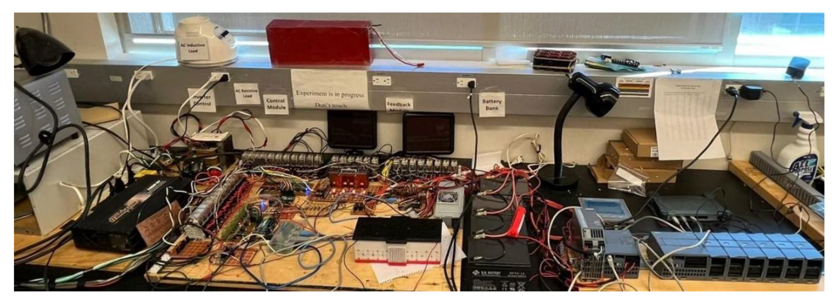
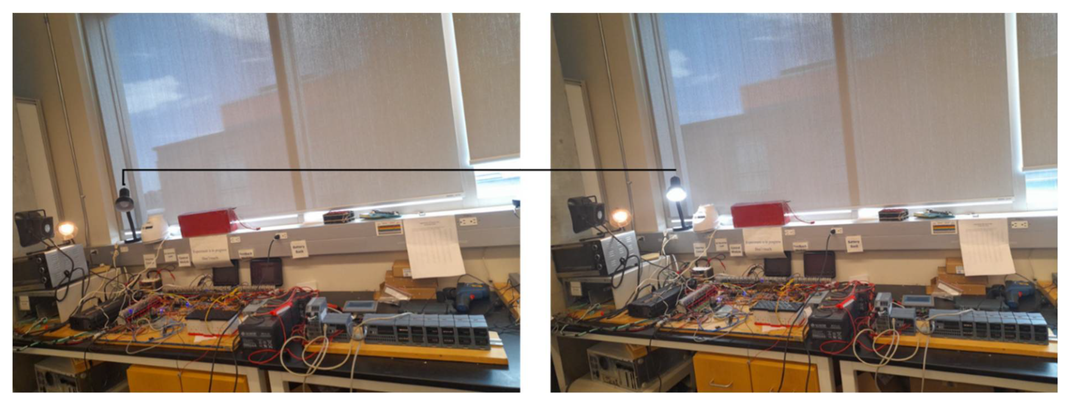
2.7. Experimental Setup of MEG
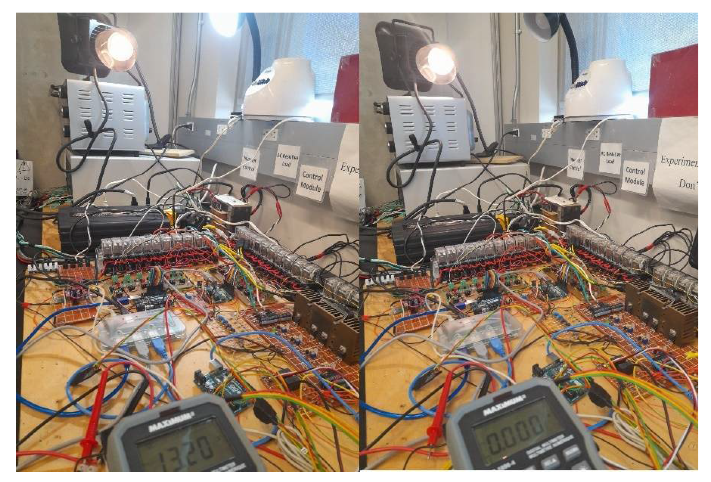
Based on the schematic design of the MEG circuitry described above, the experimental setup of the microgrid is pictured in
Figure 8. It shows the integration of multiple power sources, including the grid, PV panels, battery pack, and supercapacitors in addition to the other emulated power and energy sources by OPAL-RT co-simulation. The figure also shows the redundant control system consists of a redundancy system including three microcontroller boards and two PLCs.
The setup provides two common power buses, AC and DC buses, for supplying different types of loads, which are sizable programmatically based on relay control logic. The load can be decided manually by switching on and off any load according to user demands. Additionally, it can be set automatically by selecting based on the total amount of load the user requested. It is important to highlight one crucial contribution that, for any load mode control, restrictions of balancing between the available power source and the requested loads can be selected by considering the priority of emergency loads according to a predefined plan.
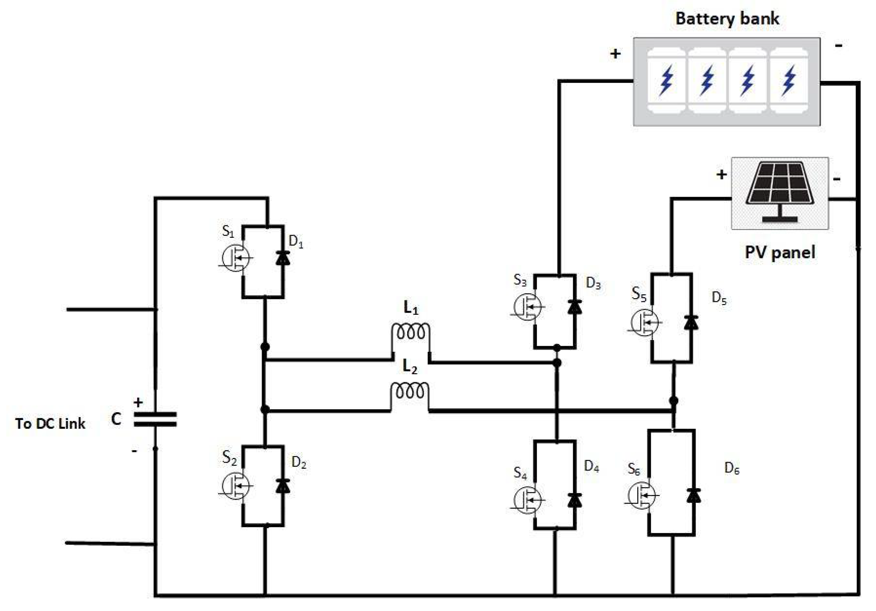
2.8. Design of the Multi-Input Converter
The proposed multi-input converter is shown in
Figure 9. The system is projected to charge the battery bank from DC-link or PV panel and discharge with the PV panel in the DC link to supply the AC and DC loads. The battery is used as an energy storage device with high energy density, and the PV is used as a renewable energy source that will reduce the supply from the grid. The converter consists of six MOSFETs, two inductors, and one capacitor, as shown in
Figure 9. The design can be modular by adding two power switches and one inductor to combine the switching leg to add more renewable energy sources or energy storage devices with high power density such as supercapacitors.
Table 2 shows the equations used to calculate the minimum values of inductors
L1 and
L2, and
Table 3 shows the design specifications of the proposed converter.
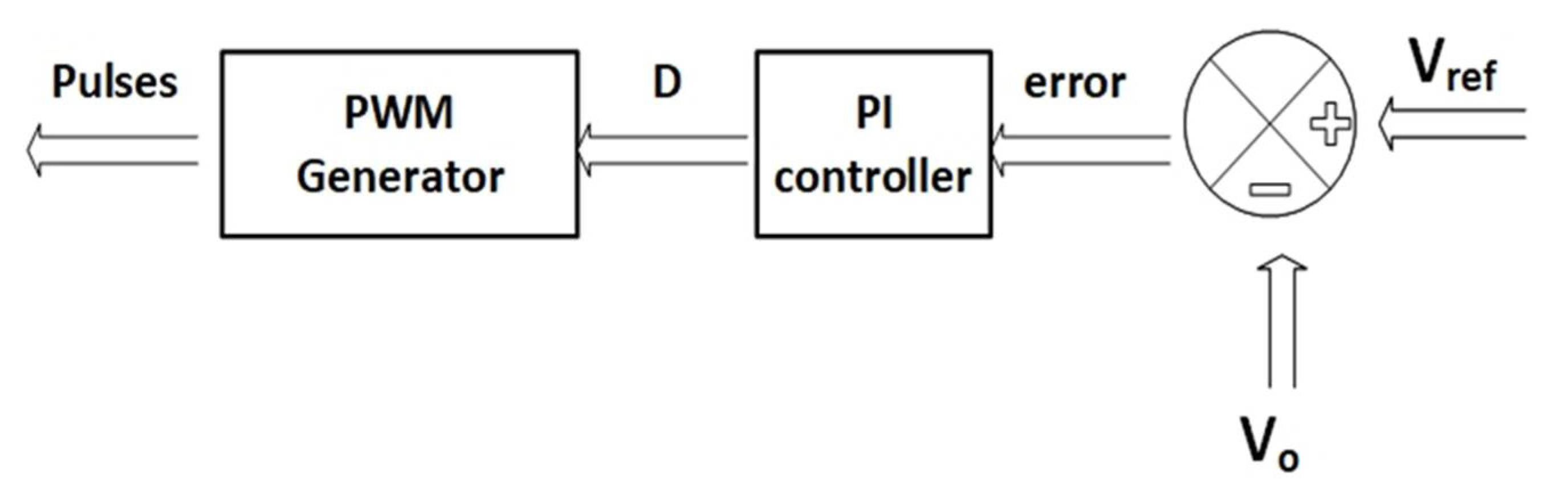
2.8.1. Converter Control
The control strategy was implemented using the proportional–integral (PI) controller; therefore, the system’s parameters can be adjusted easily by adjusting the PI gains. Flexibility and easy implementation are the main advantages of the PI controller. The error between the output voltage and the reference voltage is minimized using the PI controller, as shown in
Figure 10, to generate the desired duty ratio for the pulses of the MOSFETs in the different operation modes. To make the system underdamped, the integral coefficient is regulated to be KI = 0.3, and the steady-state error and overshoot are minimized by controlling the proportional coefficient to be Kp = 0.001.
2.8.2. Operation Modes of the Converter
The proposed converter, presented in
Figure 9, works in four different operation modes, as we will discuss later to transfer the power between the DC link and the battery bank, discharge from the PV panel and battery bank simultaneously, and exchange the energy between the PV panel and battery bank. The four operating modes of the converter are:
Mode 1: Battery Bank to DC link
The inductor
L1 is charged and discharged during this operation mode in three time intervals
T1,
T2, and
T3 to discharge the battery bank only in the DC link to charge the DC and AC loads. The switches
S2 and
S3 are turned in the first time interval to charge the
L1 and hence the inductor voltage
is described by the following equation:
In the second interval,
L1 discharge through diodes
D1 and
D4 while switches
S2 and
S3 are turned off to supply the DC link. To maintain the continuous discharging of energy from
L1 in the DC link, the switches
S1 and
S4 are turned during the third time interval instead of the diodes in
T2. The switches
S1 and
S4 operate as synchronous rectifiers to reduce the voltage drop to a level of about 0.2 V; hence, the system efficiency improved. The voltage across
L1 in
, and
is described by the following equation:
By simplifying Equation (3), and by applying the principle of volt-second balance for inductor
L1 using Equations (1) and (2), the following equation can be deduced:
Under the steady-state condition, the relation between DC-link voltage as an output and battery bank voltage as input is expressed using Equation (4).
where
D is the duty cycle ratio defined by
where
is the total period of the switching cycle, and
can be expressed as:
Additionally,
can be expressed as:
The battery bank voltage is boosted to the DC link with working in duty cycle equal
D > 0.5. The DC link charges the battery bank by reversing the current in
L1. Under the steady-state condition and taking into consideration
D to be
T1/
TS, the relation between DC-link voltage and battery bank voltage can be expressed using Equation (7).
Mode 2: PV Panel to DC Link
In this operating mode, the inductor
L2 is discharged in the DC link in three time intervals
T1,
T2, and
T3, similar to the previous operation mode to supply the DC link from the PV only. The switches
S2 and
S5 are turned in the first time interval to charge the
L2. The following equation describes the voltage across the inductor
.
In the second interval, the
L2 discharge through diodes
D1 and
D6 while switches
S2 and
S5 are turned off to supply the DC link. In the third interval, the switches
S1 and
S6 are turned on for continued discharging of
L2 in the DC link and to reduce the voltage drop of the diodes. During these intervals,
can be described by the following equations:
By applying the principle of volt-second balance for inductor
L2 using Equations (8) and (9), the following equation can be deduced:
Equation (11) shows the voltage of the DC link
VDC as an output voltage as a function of the PV panel
VPV input voltage.
where
D is the duty cycle ratio equal
, and
is the total period of the switching cycle. The following equation expresses the relation between input and output voltages, and
can be expressed as:
Mode 3: Battery Bank and PV Panel
In mode 3, the battery bank can be charged from the PV panel to extend the lifetime of the batteries during the peak hours and in sunny conditions. The PV panel work in buck operation mode to charge the battery bank, as shown in Equation (13), using the switches
S3,
S5, and
S6.
The switching sequence of the power switches in the three time intervals of the previous operation modes is summarized in
Table 4.
Mode 4: Battery Bank and PV Panel to DC Link
In this operation mode, the load from the grid can be mitigated during peak hours by simultaneously charging the loads from the battery bank and the PV panel. Inductors
L1 and
L2 are charged and discharged in five time intervals.
Table 4 shows the DC link simultaneously from the battery bank and the PV panel using Equations (15) and (16).
where
d1 is the ratio of the on-time of switch
S3 to total switching period
TS and, similarly,
d2 corresponds to switch
S2. The switching sequence of the power switches in the five time intervals of the fourth operation mode is summarized in
Table 5.
5. Conclusions
This study introduces an experimental platform for a microgrid with distinct features, such as enabling extensible and sizable AC and DC load and combining physical and emulated power sources and storage systems, aiming to increase the system flexibility by utilizing real-time simulation OPAL-RT OP4515. In addition, the design includes fail-safe and resiliency features by developing a redundant control system based on microcontrollers and PLCs. Furthermore, PLC and relay logic control enable the sizing control of the load demand.
The system combines physical and emulated power sources and energy storage, aiming to increase flexibility and diminish the limitations of including different types and sizes of power and energy sources. For example, the wind turbine as a power source and flywheel as energy storages are impractical to incorporate within an indoor experimentation setup. Using co-simulation based on interfacing hardware components with Simulink based on OPAL-RT real-time simulation opened the door to include simulated components to act on the system the way the physical sources acts. Utilizing PLC combined with relay logic control successfully shows the ability to take the system from total failure and shutdown to fail-safe with balanced load demands and power generation. Applying the redundant control by utilizing PLC and microcontrollers increased the system reliability because controllers can cover each other. It only reinforces the benefits that microgrids integrate physical and emulated energy sources with energy management and storage systems to pursue resiliency, fail-safe, and fault-tolerant capabilities.
Furthermore, a complex and long-term transition is necessary to achieve a resilient and reliable energy system, primarily based on renewable energy and high energy efficiency, aiming for sustainability, robustness, and adaptiveness. The paper presents the design of a proposed microgrid that is enriched with various power sources and energy storage along with variable AC and DC loads. This paper demonstrates a complete scenario of real-time simulation based on emulated energy sources to be integrated with the physical sources to complement the ecosystem of the proposed microgrid. Additionally, a novel fault-tolerant and fail-safe algorithm have been implemented and tested. In addition, a redundant control system based on a microcontroller array and PLC has been implemented and employed to provide the proposed microgrid’s resiliency. Testing and validation of the claimed key features and potential merits of the implemented MEG platform yield results that prove the capabilities of reliability based on the redundant control system, fail-safe operation, fault tolerance, and resiliency of the proposed system.


 ,
, 


