


Application and Analysis of Modified Metal-Oxide Memristor Models in Electronic Devices †


Department of Fundamentals of Electrical Engineering, Technical University of Sofia, 1000 Sofia, Bulgaria
†
This paper is an extended version of the papers published in 11th International Conference on Modern Circuit and System Technologies on Electronics and Communications (MOCAST 2022) IEEE Proceeding, Bremen, Germany, 8–10 June 2022.
Technologies 2023, 11(1), 20; https://doi.org/10.3390/technologies11010020
Submission received: 31 December 2022
/
Revised: 21 January 2023
/
Accepted: 26 January 2023
/
Published: 28 January 2023
(This article belongs to the Special Issue MOCAST 2022)
Abstract
:The design of memristor-based electronic circuits and devices gives researchers opportunities for the engineering of CMOS-memristor-based electronic integrated chips with ultra-high density and various applications. Metal-oxide memristors have good compatibility with the present CMOS integrated circuits technologies. The analysis of new electronic circuits requires suitable software and fast-functioning models. The main purpose of this paper is to propose the application of several modified, simplified, and improved metal-oxide memristor models in electronic devices and provide a comparison of their behavior, basic characteristics, and properties. According to this, LTSPICE is utilized in this paper because it is a free software product with good convergence. Several memristor-based electronic circuits, such as non-volatile passive and hybrid memory crossbars, a neural network, and different reconfigurable devices–filters, an amplifier, and a generator are analyzed in the LTSPICE environment, applying several standards and modified metal-oxide memristor models. After a comparison of the operation of the considered schemes, the main advantages of the modified metal-oxide memristor models, according to their standard analogs, are expressed, including fast operation, good accuracy, respectable convergence, switching properties, and successful applicability in complex electronic circuits.
1. Introduction
The memristor is a highly nonlinear, passive electronic one-port element with switching and memory properties [1]. It was predicted by Chua in 1971, according to the missing direct relation between the electric charge and magnetic flux linkage and symmetry of the relations between the basic electric quantities–current, voltage, flux, and charge [2]. Its memory and switching properties are related to the transformation of a defect-impurity composition under applied voltage signals, leading to a change in resistance. According to the materials they are based on, there are several basic types of memristors [3]. In the scientific literature, they are described as titanium dioxide [4,5], hafnium oxide [6], tantalum oxide [7], niobium oxide [8], polymeric [9], ferroelectric [10], spintronic [11], other types of different memristor elements [12]. In recent years, metal-oxide memristors based on transition metals, are under intensive investigation due to their stable characteristics and parameters, very small dimensions in the nanometer range, low power consumption, and good compatibility with the present CMOS (complementary metal oxide semiconductor) integrated circuits with ultra-high density [13]. Memristors are potentially applicable in different types of electronic circuits and devices, such as artificial neurons and neural networks [14,15], nonvolatile memory crossbars [16,17], reconfigurable digital and analog circuits, filters [18,19], amplifiers [20], generators [21,22], logic gates, chaotic systems, and many others [23,24,25]. In memory crossbars, the memristors are used for accumulating logical information, and their state is changed by the external voltage or current pulses [16,24,26]. In such electronic circuits, memristors operate in a hard-switching mode in writing and erasing information, and their switching properties are important for the fast operation of memory devices [24,27]. In artificial neural networks, memristors are mainly used in the synaptic circuits as storing elements for the synaptic weights [24,25,28]. During the change in weights, the memristors normally operate in a soft-switching mode. Memristors are applicable to in-memory computing electronic schemes, brain-inspired computing devices, and many other circuits with artificial intelligence [28]. In reactance-less relaxation oscillators, memristors operate in a soft-switching mode but with a change in the state variable in comparatively broad ranges [21,22]. Memristors are applied for the avoidance of inductors and capacitors in the generators’ integrated circuits and for minimization of the chips’ area. In some reconfigurable memristor-based linear circuits and devices, as filters [18,26] and amplifiers [20], the memristors operate at low-level signals as linear resistors. Then, the amplitude of the applied signals has to be lower than the memristor activation threshold. The characteristics of these memristor-based circuits are accurately tuned by external voltage pulses.
The design and analysis of complex memristor-based electronic circuits require an appropriate software environment such as SPICE (simulation program with integrated circuits emphasis), Verilog-A, and others [29], and respective fast-operating memristor models [30,31]. In the last several years, LTSPICE (linear technology SPICE), along with the other SPICE products, have been preferred by many researchers owing to their free license, simple and user-friendly interface, and improved convergence [32]. The number of electronic elements and connections between them in LTSPICE is not restricted, and this gives the engineers the possibility to analyze and simulate very large and complex electronic circuits [32,33]. This is the main reason for LTSPICE software to be applied and used in the present work. The latest versions of LTSPICE software for Microsoft Windows and Mac operating systems (OS) with detailed instructions can be freely downloaded and installed using the link: https://www.analog.com/en/design-center/design-tools-and-calculators/ltspice-simulator.html (accessed on 21 September 2022).
The existing research in the scientific literature on classical metal-oxide memristor models, such as those of Strukov-Williams [1], Joglekar [4], Biolek [34], Lehtonen-Laiho [35], and others [36,37], have some disadvantages, together with their positive properties. For example, Strukov-Williams, Joglekar, and Biolek’s models are simple and fast-operating ones, but they have comparatively low accuracy, do not completely represent the nonlinear dopant drift, are dependent on the applied voltage, and do not include activation thresholds, which are very useful for the separation of the main operating modes of metal-oxide memristors [3,34]. Lehtonen-Laiho’s [35] model and Williams’ model for tantalum oxide memristors [7] have very high accuracy and good properties, but they contain a high amount of elementary mathematical operations, and due to this, they require serious computing resources and time and are not very appropriate for the simulation of complex memristor-based circuits with a large number of memristors. Physically based compact metal-oxide memristor models are used for the analysis of resistance-switching effects and the operation of memristor-CMOS-based resistive random-access memories, logic circuits, and many other electronic schemes and devices [29,30]. Variations in memristor parameters and characteristics play an important role for RRAM devices in both computing and memory applications. In many physics-based and compact memristor models, the variations of characteristics and parameters are represented [38,39].
To partially overcome the disadvantages of some standard memristor models, several modified metal-oxide memristor models were proposed [15,17,19]. These models are mainly based on the classical memristor models of Joglekar, Biolek, and Lehtonen-Laiho. These modified models are improved by the approximation and simplification of their mathematical expressions, by the inclusion of activation thresholds, by applying highly nonlinear voltage-dependent terms in state equations, and by utilizing a differentiable step-like function, instead of the classical non-differentiable Heaviside function [33]. The activation thresholds in the modified memristor models allow them to operate at different signal levels in soft-switching and hard-switching modes and as linear resistors and to be applied in neural networks, nonvolatile memory matrices, and reconfigurable electronic circuits [17]. The modified models [15,17,19] contain a sufficient number of parameters, which are used for their tuning according to the experimental current-voltage characteristics of metal-oxide memristors. They correctly represent the nonlinear ionic dopant drift in metal-oxide memristor elements and are able to operate at high frequencies.
The aim of this paper is to propose a comparison of several modified models [15,17,19] and classical metal-oxide memristor models, including their behavior, properties, and application in different memristor-based electronic circuits and devices—passive and hybrid memory crossbars, low-pass, high-pass, band-pass and band-stop filters, a memristor-based generator, an amplifier, and a neural network.
For the achievement of the aim of this paper, the following tasks are solved. The modified LTSPICE memristor models [15,17,19] are applied and analyzed in passive and hybrid memristor matrices, in a neural network with memristor-based synapses, in reconfigurable circuits including filters, a generator, and an amplifier. The analysis of these memristor-based devices is realized in the LTSPICE environment. A comparison of the modified models together with the classical models of Strukov-Williams, Joglekar, Biolek, and Lehtonen-Laiho is made according to their behavior in electronic circuits and the use of several important criteria-complexity, accuracy, simulation time, operating frequency, and switching properties [3,33]. The main advantages of the modified metal-oxide memristor models are confirmed as high operating speed, good switching properties and accuracy, high operating frequencies, improved convergence, and applicability for the design of different complex electronic circuits with a large number of memristors in ultra-high-density integrated chips.
The used LTSPICE memristor library models are included in a unified and open library [33], together with many other standard and modified memristor models, memristor-based electronic circuits, and instructions for their use. The metal-oxide memristor models’ library is freely available for use at the following website: https://github.com/mladenovvaleri/Advanced-Memristor-Modeling-in-LTSpise (accessed on 23 September 2022).
The rest of this paper is organized as follows. In Section 2, a brief description of the applied classical and modified metal-oxide memristor models is presented. A discussion on the generation of the respective LTSPICE memristor library models is presented in Section 3. The next Section 4 represents the analysis of several memristor-based electronic devices, including neural networks, passive and hybrid memory crossbars, low-pass, high-pass, band-pass and band-stop filters, amplifiers, and oscillators, and applying classical and modified metal-oxide memristor models. A comparison of the considered memristor models, according to their behavior in electronic circuits and using several basic criteria, is expressed in Section 5. In Section 6, a discussion of the obtained results is included. The conclusion is presented in Section 7.
2. A Description of the Applied Memristor Models
In this section, general information about memristors and a description of the considered classical and modified metal-oxide memristor models is presented for a better understanding of the operation of memristors in electronic circuits and devices. In the scientific literature, many physics-based memristor models are presented [27,29]. The efforts of researchers working in this field of science are related to the representation of the cycle-to-cycle variations of the memristor parameters, the enhancement of the reliability and stability of the memristor models, and the improvement of the endurance of memristor elements [38,39]. Each memristor model is expressed by a system containing two math equations. The first one represents the relationship between the memristor current i and voltage v. It includes the memristor ON-state and OFF-state resistances—RON and ROFF—and the state variable x. In most cases, the state variable x is expressed as a ratio between the length of the doped region w and the whole memristor length D. The second one is the so-called state differential equation. It relates the time derivative of state variable x and the memristor current i (or voltage u). To derive the current–voltage and state–flux relationships, the initial value of the state variable x0 and the excitation signal is used for the solution of the described system of equations.
2.1. Classical Memristor Models
In the scientific literature, different standard metal-oxide memristor models are described [1,4,5,27]. Here, the mainly used classical models of Strukov-Williams [1], Joglekar [4], Biolek [34], and Lehtonen-Laiho [35] are considered.
2.1.1. Strukov-Williams Memristor Model [1]
This memristor model is especially applicable to titanium dioxide memristor nanostructures [1]. It has very simple math equations presented by the system (1). The applied parabolic window function x(1 − x) is used for the limitation of the memristor state variable x in the range (0, 1).
The physical constant k is dependent on memristor parameters [1]:
where µ is the ionic dopant drift mobility. From a physical point of view, the mobility of the oxygen vacancies depends on the electric field intensity, and it increases with the applied voltage. Strukov-Williams’ memristor model uses ionic mobility with a constant value.
2.1.2. Joglekar Memristor Model [4]
The main difference between Joglekar’s memristor model and Strukov-Williams’ model is in the applied window functions. Joglekar’s window function is a higher-order polynomial, where p is a positive integer exponent. Strukov-Williams’ window function is a special case of the Joglekar function when p = 1. The Joglekar memristor model is more flexible, owing to the use of the parameter p. It is presented by system (3).
Strukov-Williams’ and Joglekar’s window functions have a disadvantage, known as a terminal state problem [3,4]. Sometimes, when the state variable x reaches the limiting values of zero and the unity, the model is unable to represent the continuous change in the state variable x in accordance with the equivalent flux linkage Ψ.
2.1.3. Biolek Memristor Model [34]
This memristor model is similar to the previous ones, but the applied window function is quite different [34]. It depends not only on the state variable but also on the direction of the memristor current. The Biolek memristor model is represented by (4) [34].
The applied window, frequently stated as the classical Biolek window function, uses the standard Heaviside step function [34], which is a non-differentiable one and sometimes is a precondition for the occurrence of convergence problems in the SPICE environment [32,40]. In many of the modified memristor models discussed in the next paragraph, the Heaviside step function is replaced by a smooth and differential sigmoidal alternative for the improvement of the model’s convergence. Compared to Joglekar and Strukov-Williams’ windows, the standard Biolek window function circumvents the terminal state problems [3,34,36].
2.1.4. Lehtonen-Laiho Memristor Model [35]
This memristor model has a higher complexity, according to the previously discussed models. The equation expressing the current–voltage relationship contains two terms. The first one contains the state variable and the memristor voltage and is related to the memory effect of the element [1,3]. The second term expresses the rectifying effect of the memristor in a hard-switching mode. The state differential equation includes the standard Biolek window function, which is applied for the limitation of the state variable and for the representation of the boundary effects [3,34]. The model is presented by (5) [35].
The coefficients β, n, α, χ, γ, a, and m are applied for tuning the memristor model according to experimental current-voltage characteristics [35]. The Lehtonen-Laiho model is applicable to different types of metal-oxide memristors, such as titanium dioxide, hafnium oxide, and others [1,4,6]. It has high accuracy and can correctly operate at high-frequency signals. A disadvantage of this model, according to the previously discussed models, is its higher complexity, owing to the use of many elementary math operations.
2.2. Modified Memristor Models
In the considered modified memristor models, an improved version of the standard Biolek window function is used [30]. It is represented by the first equation of formula (6). It includes a flat step-like function, denoted by stpp(i), which is expressed by the next Equation (6) [3,15,17,19].
The second equation of (6) represents a smooth and differentiable step-like function stpp(i), which is a modified version of the original Heaviside step function [41]. The parameter s is applied to change the steepness of the function in the region of switching. The modified step function is suitable for realization in the SPICE environment and for a partial circumvention of convergence problems.
2.2.1. A Modified Memristor Model Based on Biolek and Lehtonen-Laiho Models (Model A11) [17]
The considered memristor model is presented by (7). This memristor model uses a simple current–voltage relationship, which is expressed by the first equation of (7). The activation threshold vthr is applied in the state differential equation. If the memristor voltage is lower than the activation threshold vthr, then the state variable does not alter, and the memristor behaves as a linear resistor. When the voltage exceeds the activation threshold, then the state variable changes in accordance with the equivalent flux linkage.
In the state differential equation, the time derivative of the memristor state variable x is related to the voltage, applying a sine-hyperbolic dependence [17]. The coefficients k1 and k2 are used for the adjustment of the memristor model. This model operates at higher frequencies, correctly representing the boundary effects. It has good accuracy. According to the standard Lehtonen-Laiho model, the discussed modified memristor model has a simplified structure and could be applied for the analysis of complex memristor-based electronic circuits and devices [17].
2.2.2. A Modified Model Based on Lehtonen-Laiho Memristor Model A12) (Model A12) [15]
This metal-oxide memristor model is based on the standard Lehtonen-Laiho model. It is simplified, according to its classical analog, by the approximation of the described equations. It is represented by (8). In the first equation of (8), the relation between the current and voltage is based on a sine-hyperbolic dependence on the voltage and a fixed power of the state variable x.
In the state differential equation, an exponential dependence on the voltage is applied. The model includes an activation threshold vthr for the separation of the operating modes of the memristor [15]. The coefficients k1, k2, k3, and k4 are used for the adjustment of the memristor model, which is able to operate with high-frequency signals.
2.2.3. A Modified Memristor Model Founded on Strukov-Williams and Lehtonen-Laiho Models (A13) [19] (Model A13)
This modified memristor model is based on a simple relation between the current and voltage and includes a nonlinear dependence between the time derivative of the state variable and the memristor voltage. The applied activation thresholds allow the memristor model to be used for the analysis of non-volatile memory crossbars and memristor-based neural networks at high-frequency impulse sequences.
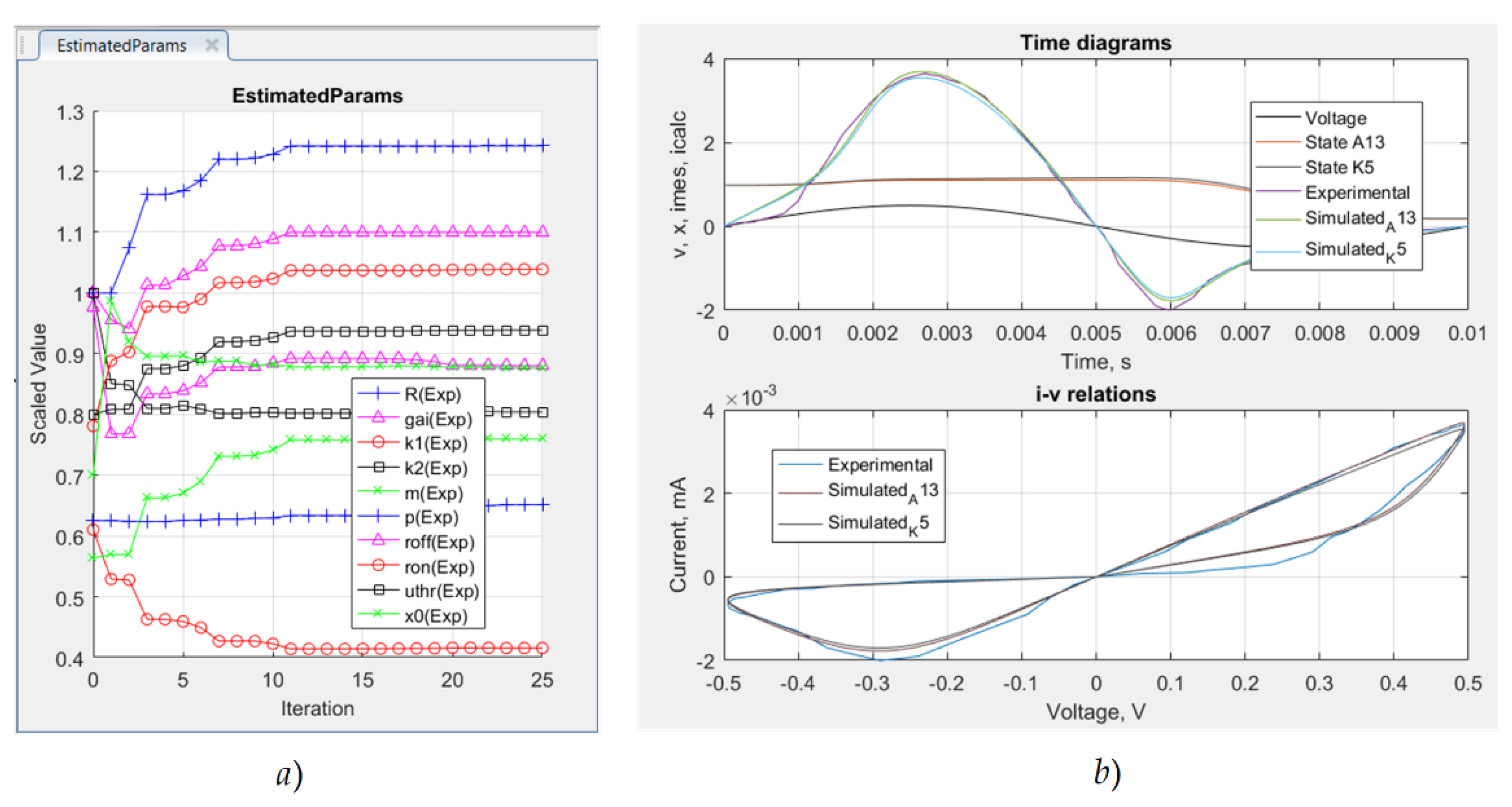
Parameter estimation and the adjustment of the considered memristor models (A11, A12, A13, Strukov-Williams, Joglekar, Biolek, and Lehtonen-Laiho models) are realized by comparison to the experimental current-voltage characteristics of metal-oxide-based memristors. Gradient descending and simulated annealing algorithms [19,42] are applied for the minimization of the root mean square error and to obtain the optimal values of the memristor models’ parameters.
An example of the optimization procedure is presented in Figure 1. It is related to the modified memristor model A13 for the representation of the processes of parameter estimation and obtaining the optimal values of the coefficients of the model. The trajectories of the memristor model parameters during the estimation procedure are presented in Figure 1a for the observation of their alteration. The derived optimal values of the memristor model parameters are applied to obtain the time diagrams of the memristor current and the corresponding current-voltage characteristics, which are presented in Figure 1b for comparison with the experimental memristor characteristics. The estimation procedures of the other considered memristor models are similar to the discussed one.
3. A Generation of LTSPICE Memristor Library Models
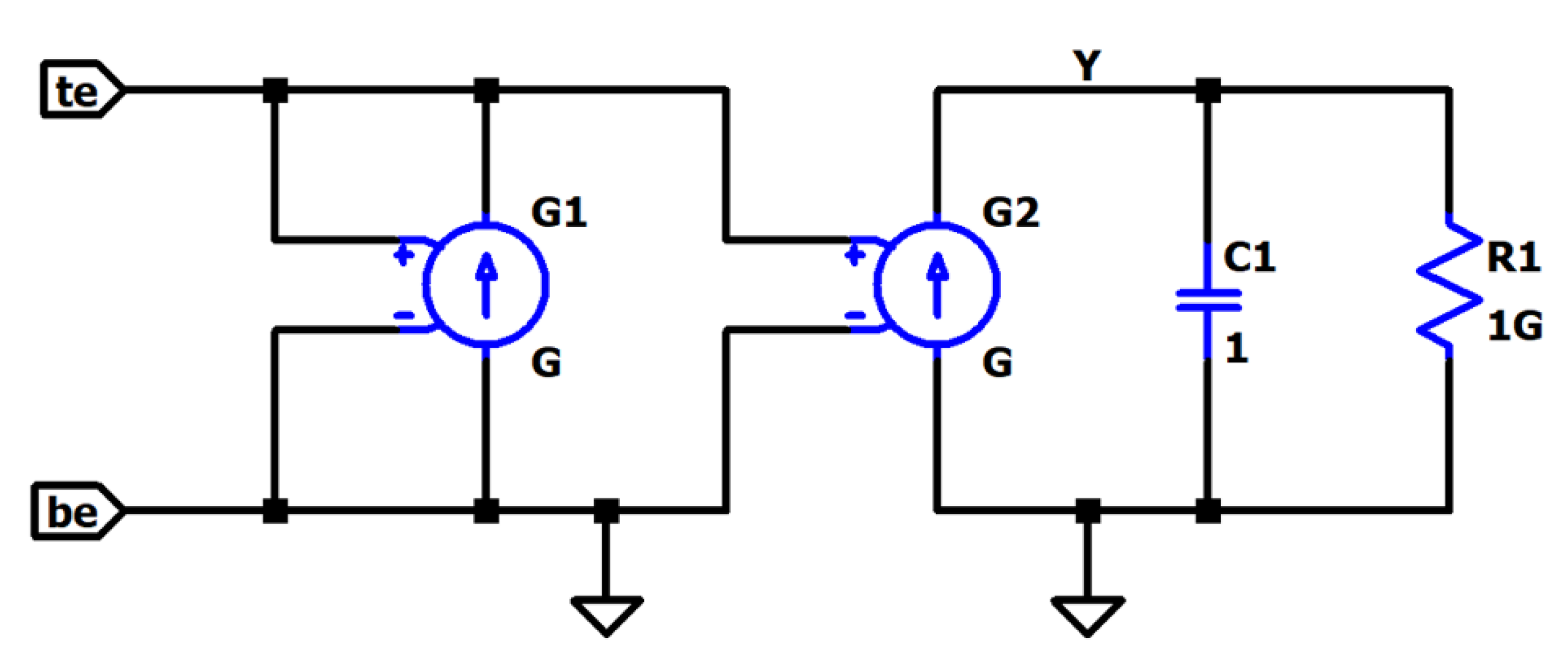
In this section, a compact equivalent LTSPICE schematic of the previously discussed memristor models is presented and explained in detail. The realization of the LTSPICE models of the considered metal-oxide memristors is based on the schematic, as presented in Figure 2 for a description of its basic blocks and operation. The equivalent circuit shown in Figure 2, is applied for the generation of all the considered standard and modified metal-oxide memristor models. The schematic is based on the two main equations in each memristor model: the current–voltage relationship and the state differential equation, relating the time derivative of the memristor state variable and the current (voltage). The memristor voltage is applied between its terminals, which are usually denoted by te (top electrode) and be (bottom electrode). Frequently, in the scientific literature, these electrodes are denoted by a (the anode) and c (the cathode). The current of the voltage-controlled current source G2 expresses the time derivative of the memristor state varies according to the corresponding state differential equation of the memristor model. The capacitor C1 is connected in parallel to it for the integration of its current and to obtain the memristor state variable. Its voltage is proportional to the state variable. The resistor R1 is connected in parallel to the capacitor C1 and ensures a smooth change in the voltage across it. In this way, the resistor R1 partially prevents convergence problems in the SPICE environment. The potential of the terminal Y is proportional to the memristor state variable. The memristor current is represented by the voltage-controlled current source G1 [3,33,40].
A simple LTSPICE code of the Joglekar memristor model [3,4,33] is presented below for additional explanations and a discussion on the structure and operation of the equivalent schematic of memristor models.
- 1
- . subckt K2 te be Y
- 2
- . params ron = 100 roff = 16e3 k = 10e3 pp = 1
- 3
- C1 Y 0 1 IC = 0.3
- 4
- Rad Y 0 10G
- 5
- G2 0 Y value = {(k*V (te,be)*(1/(ron*(V(Y)) + roff*(1 − V(Y))))*(1 − pow((2*(V(Y)) − 1),(2*pp))))}
- 6
- G1 te be value = {V(te,be)*((1/(ron*(V(Y)) + roff*(1 − V(Y)))))}
- 7
- . ends K2
The first row of the code defines the sub-circuit of the Joglekar memristor model, which is abbreviated as K2. The electrodes of the memristor element-te, be, and Y is also included. The memristor model parameters RON, ROFF, k, and pp are included in the second row of the code. The capacitor C1, applied for integration of the time derivative of the state variable, is described in the third row, and its initial voltage, denoted by IC, is proportional to the initial value of the memristor state variable x0. The additional resistor Rad, attached in parallel to the capacitor C1, has a value of 10 GΩ and is expressed in the next row. The voltage-controlled dependent source G2 is represented in the fifth row of the code. Its conductance is proportional to the time derivative of the memristor state variable and, in the present case, contains the constant k, the memristor voltage V(te,be), the memristance (1/(ron*(V(Y)) + roff*(1 − V(Y))), and the Joglekar window function, expressed as (1-pow((2*(V(Y)) − 1),(2*pp))). The sixth row represents the dependent source G1, which conductance is proportional to the memductance ((1/(ron*(V(Y)) + roff*(1 − V(Y))))). The description of the memristor model finishes with the command “ends”.
4. Memristor-Based Electronic Devices–Analysis in LTSPICE Environment
In this section, several memristor-based electronic circuits and devices are presented and analyzed in the LTSPICE environment using the classical and modified memristor models discussed in Section 2.
4.1. A Passive Memristor Memory Crossbar
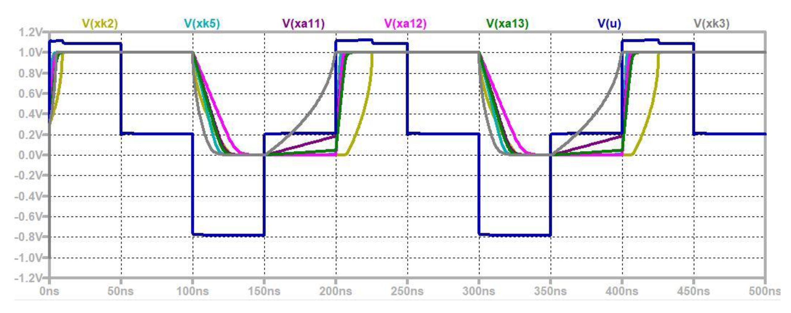
In Figure 3, a schematic of a passive and simple memristor-based memory array of 25 memristors is shown for the description of its functioning and structure. It includes five-word lines and five-bit lines, respectively. Loading a bit of information in a given memristor cell is realized by its selection, applying a demultiplexer, and using a voltage pulse. The own resistance of the memory crossbar rims is about 2.2 Ω and could be ignored with respect to the resistance of the memristor cells. For writing a logic unity, a positive impulse with a level of 1.1 V and a period of 100 ns is applied. For writing a logic zero, a voltage pulse with the same duration and a level of −1.1 V is used. For reading the information from the crossbar, positive impulses with a level of 0.1 V are used. The writing and erasing processes in the memristor memory crossbar are represented in Figure 4 with the time diagrams of the memristor voltage, the alteration of their memristance, and the corresponding state variables. The standard and modified memristor models, described in Section 2, are used for the analysis of the memory crossbar in the LTSPICE environment [32]. The amplitude of the reading impulses is lower than the memristor activation threshold vthr, and the resistance of the memristor is not changed. In this way, the information stored in the memristor elements is not affected. The parasitic sneak paths in the memristor memory array do not significantly influence its normal operation due to the presence of high-resistance reversely biased memristors [24,33].
The time diagrams for the voltage, memristance, and state variable, according to the used classical and modified memristor models, are represented in Figure 4 for the confirmation of the proper operation of the considered memory crossbar and for the comparison of the results. The voltage across the memristor is a sequence of pulses with a duration of 50 ns and different polarities and levels. The applied memristor models have a similar behavior, according to the range of memristance’s change. The state variable x alters in the range (0.04, 0.97) and is related to a hard-switching operation. The memristance changes between 140.3 Ω and 14.7 kΩ. In the writing processes, the Lehtonen-Laiho model and the modified ones represent a rapid change in memristance, presenting their very good switching properties, while the Joglekar and Biolek memristor models are related to a slower alteration of the equivalent resistance. This is an advantage of the modified metal-oxide-based memristor models, according to the Joglekar and Biolek models, and is related to the application of exponential, sine hyperbolic, and polynomial relationships between the time derivative of the memristor state variable and the voltage, representing their better switching behavior. A small change in the memristance during the reading procedures was observed for the Biolek model due to the absence of activation thresholds. According to the modified memristor models and Lehtonen-Laiho model, the memristance does not alter during the reading processes.
4.2. A Hybrid Memory Crossbar
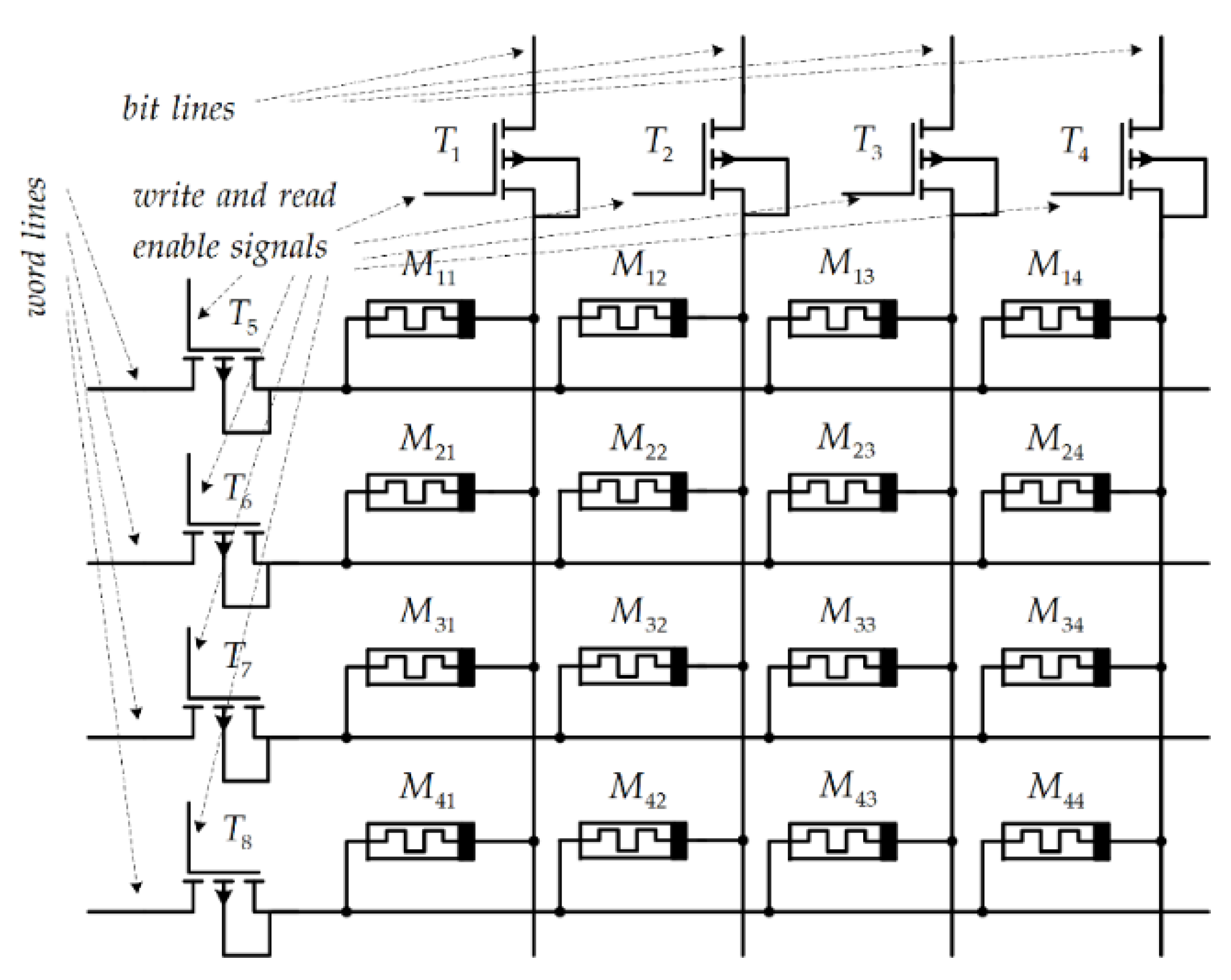
A hybrid memory crossbar based on memristors is presented in Figure 5 for the clarification of its structure and operation. It contains sixteen memristors and eight MOS transistors. The memristors are used as storing elements, while the transistors operate as write-enable and read-enable switches. To enable writing a logical zero or unity in a given memristor, positive voltage pulses must be applied to the gates of the respective MOS transistors.
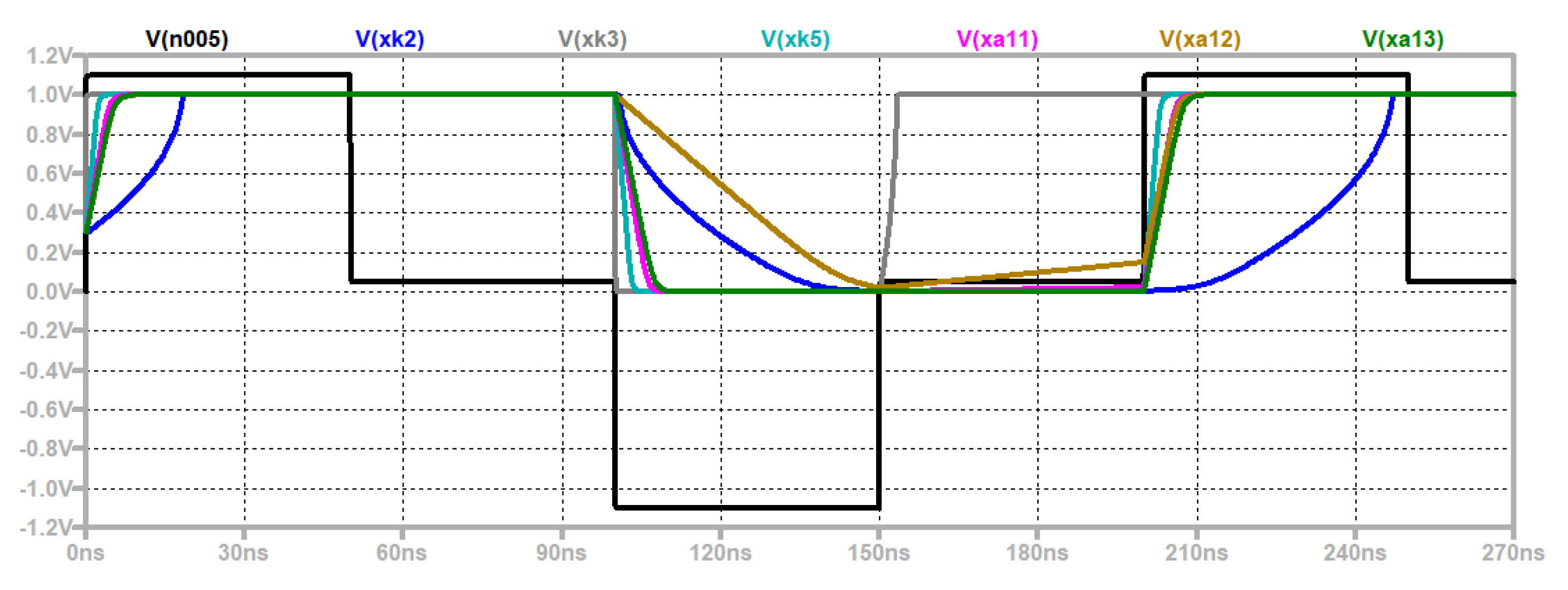
The time diagrams of the applied pulses, the state variables, and the memristor voltage are presented in Figure 6 for confirmation of the proper operation of the memristor models and for their comparison. According to the rate of changing the state variable and memristance, the modified model A11 represents the lowest switching time and the highest switching speed, respectively [24,33].
4.3. A Memristor-Based Neural Network
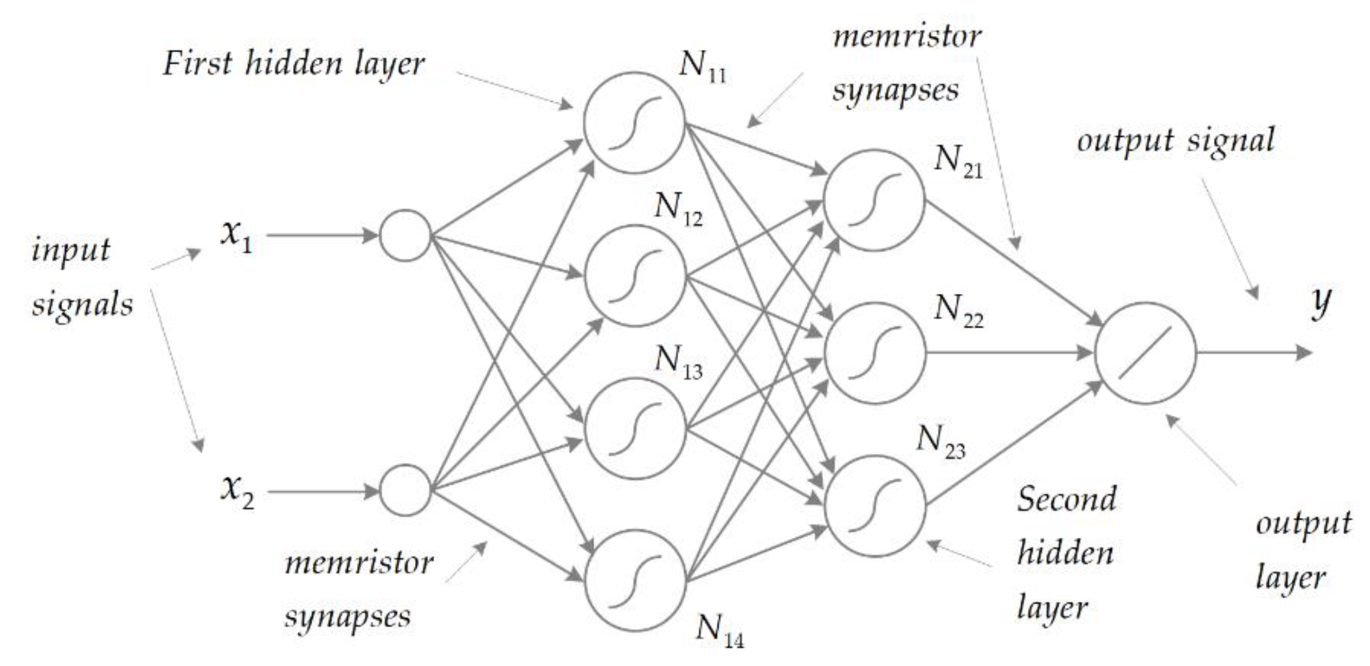
A simple feed-forward memristor-based neural network is presented in Figure 7 for a further description of its structure and operation [15]. The network is used for the logical XOR function emulation. It contains two input nodes to apply the input logical signals x1 and x2. The neural net contains two hidden layers and an output layer. The first hidden layer is made of four neurons—N11, N12, N13, and N14 with a nonlinear activation function, and the second one contains three neurons—N21, N22, and N23. The output layer contains a neuron with a linear activation function. The synaptic bonds between the neurons are memristor-based. Supervised learning is applied for the adjustment of the synaptic weights, which are founded on memristors [15,17,19]. The other elements of the artificial neural network are based on CMOS transistors.
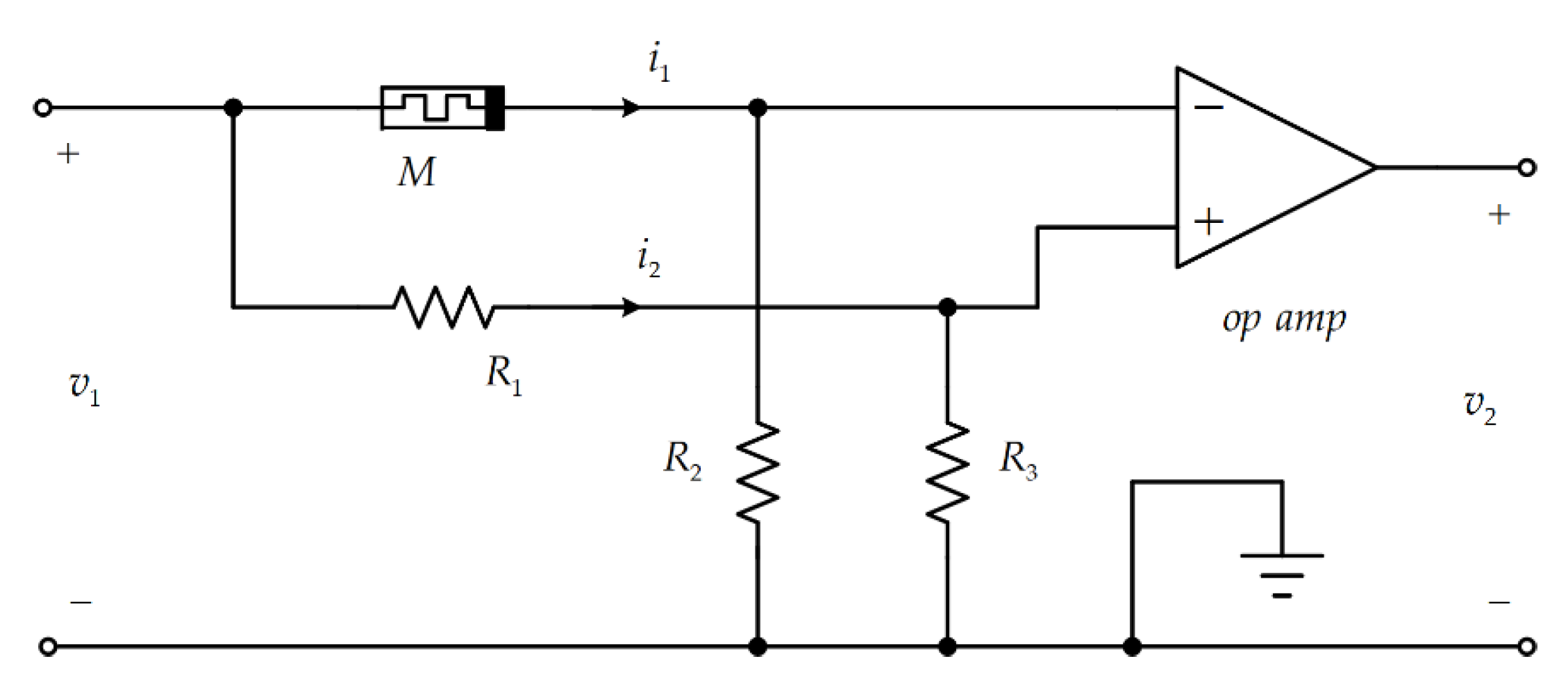
The schematic of the applied synaptic circuit is presented in Figure 8 for a description of its topology and principle of operation [15,17,19]. It contains a memristor, three resistors, and an operational amplifier. The input voltage signals are applied to two voltage dividers, which are connected parallel to each other.
The first voltage divider is made by the memristor M and the resistor R2; the second one contains the resistors R1 and R3. The principle of operation for the considered synaptic circuit is based on a comparison of the voltage drops across the resistors R2 and R3. The weight of the described synaptic circuit w as a function of the memristance M is [15]:
The memristance M and the corresponding synaptic weight w are altered by external voltage pulses. After a simple transformation of (10) and applying R2 = R3, it is obtained that if R1 = M, then the synaptic weight can be expressed as w = 0. Positive synaptic weights are derived if M > R1. When M < R1, then w < 0. The scaling of the weights is derived by changing the transfer coefficient kv of the operational amplifier. The input voltage signal is a sequence of negative and positive impulse packages. A pulse with a length of 1 µs and a level of 1 V leads to a change in the synaptic weight by 0.23. A negative polarity voltage signal is used for increasing the weights, while their decreasing positive pulses are used. The error signal is represented as a difference between the desired output signal and the respective actual output signal. The level of the error signal is many times lesser than those of the input logic signals. The proper functioning of the neural net and the appropriate convergence of the training procedures are established.
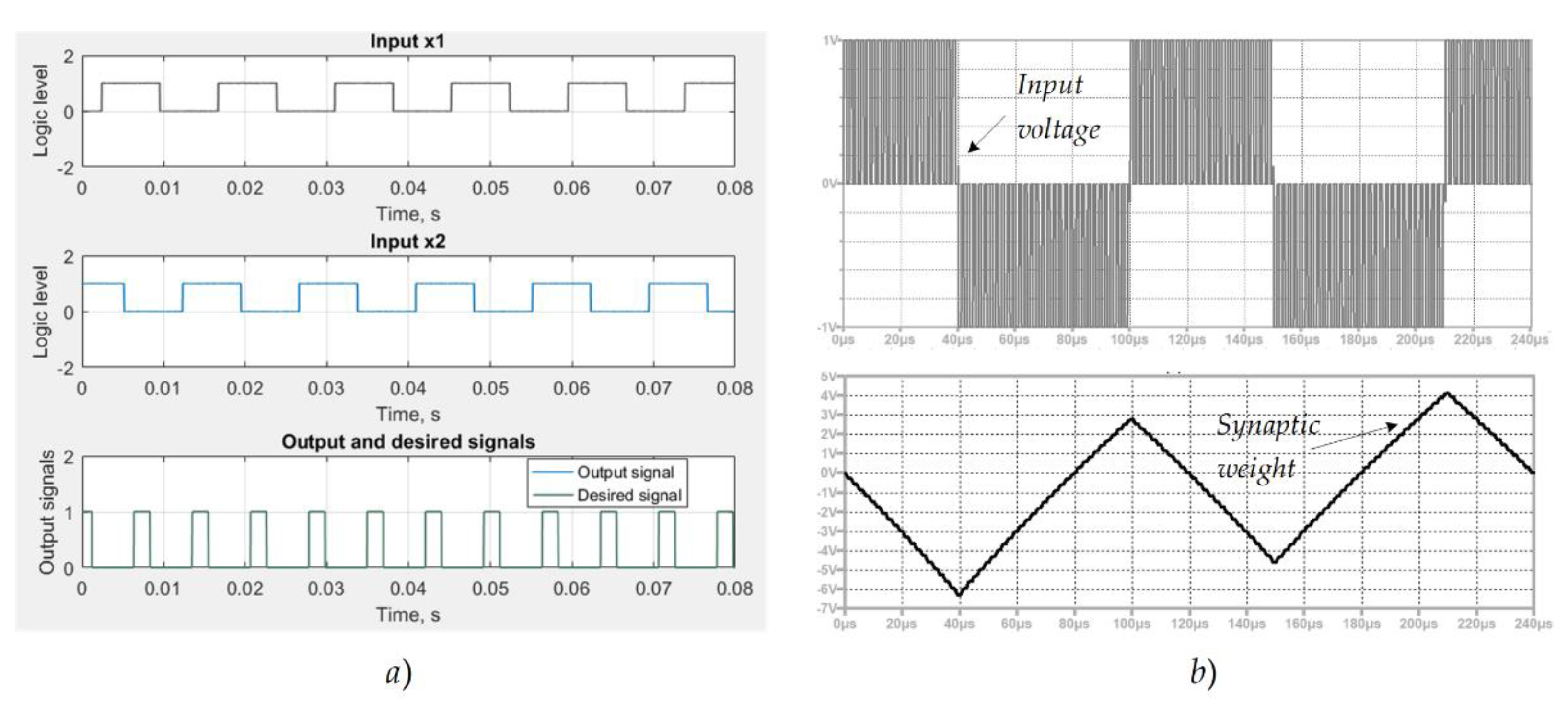
The diagrams of the input voltage signal x1 and x2 for testing the neural net are presented in Figure 9a for the expression of the logic signals. They correspond to logic ones and zeros for the emulation of XOR logic operations. The input signals for training the neural net are very similar; they are shifted according to the testing signals to obtain more realistic results. The diagrams of the input signals of the synaptic circuit and its weight alteration are shown in Figure 9b for the description of its adjustment process. The input signals are a sequence of negative and positive packages of pulses.
The actual and the desired output signals after testing the neural network are represented in Figure 9a for the confirmation of their good matching. The signal of the error of the net is expressed as a difference between the actual and the desired output signals. Its amplitude is about several thousand times less compared to those of the input signals. The proper operation of the net and the good convergence of its training are established.
4.4. A Memristor-Based Amplifier
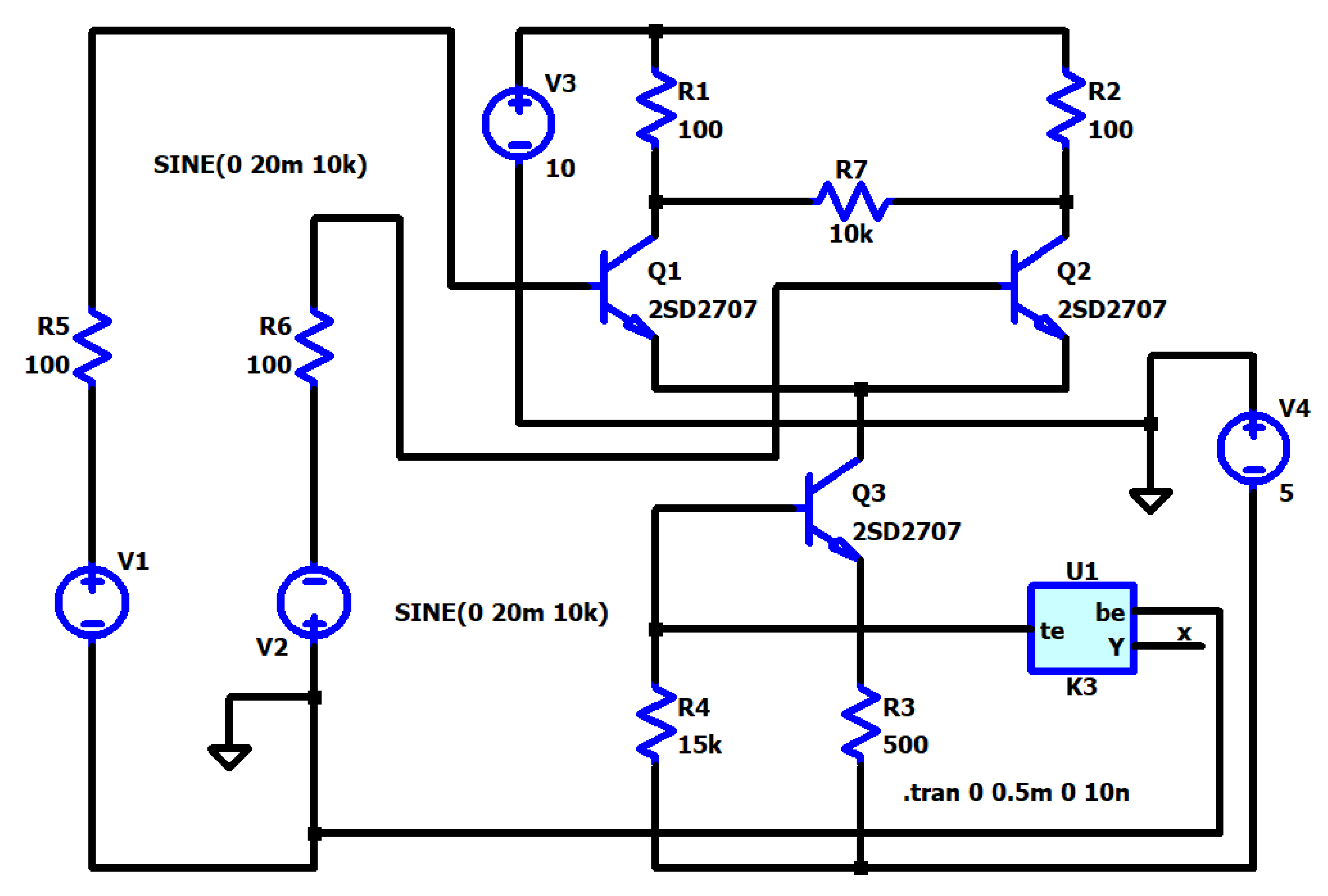
A differential amplifier based on the metal-oxide memristor and transistors [20] is represented in Figure 10 for the description of its structure and operation. It contains a memristor element in the feedback electronic circuit and three bipolar transistors of the NPN type. The resistors R5 and R6 represent the internal resistances of sources V1 and V2. The resistors R1 and R2 are applied for the limitation of the collector currents of the transistors Q1 and Q2. The output voltage signal is derived between the collectors of the elements Q1 and Q2, and it is proportional to the difference between the input signals. In the present case, the memristor element operates in a soft-switching state. The tuning of its memristance by external voltage impulses leads to a change in the transfer coefficient of the amplifier.
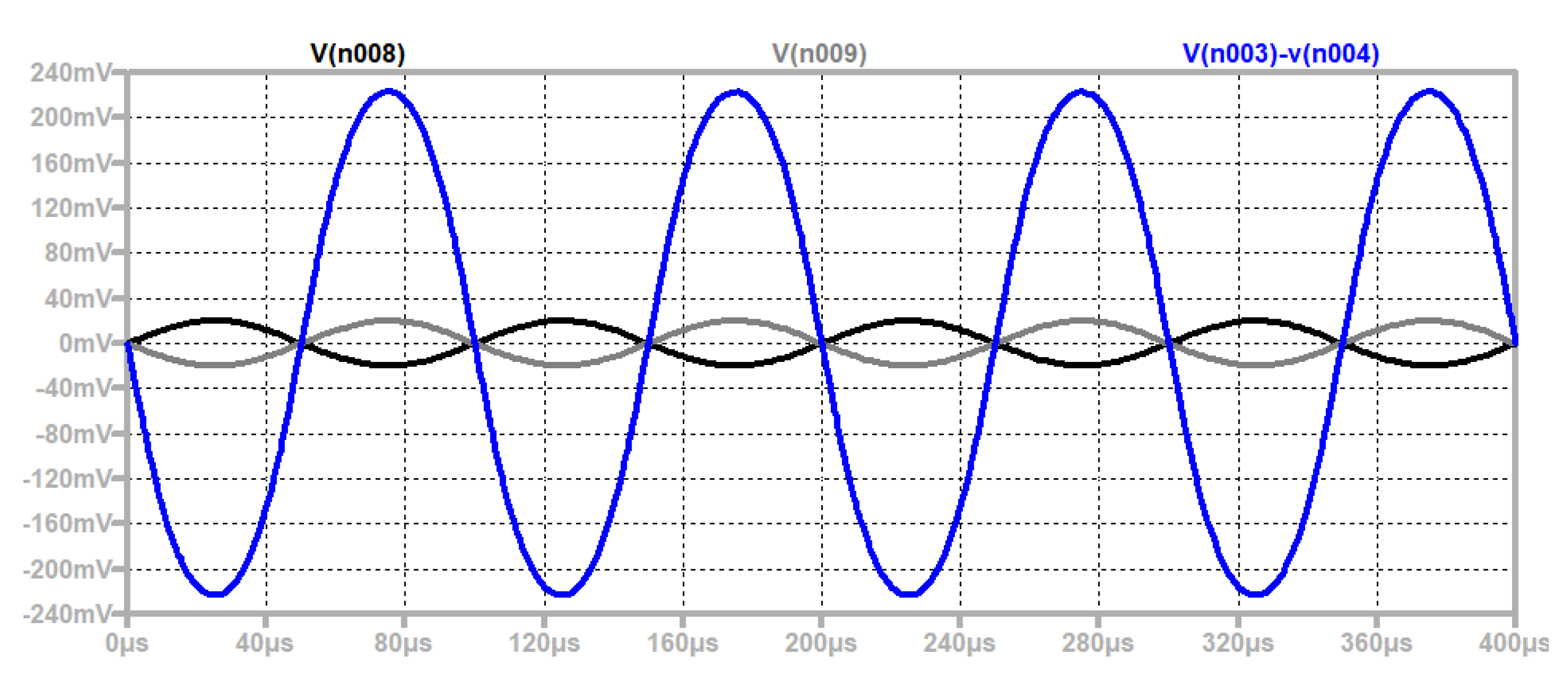
The time graphs of the input and output sinusoidal signals are presented in Figure 11 for confirmation of the correct operation of the amplifier.
4.5. A Memristor-Based Generator
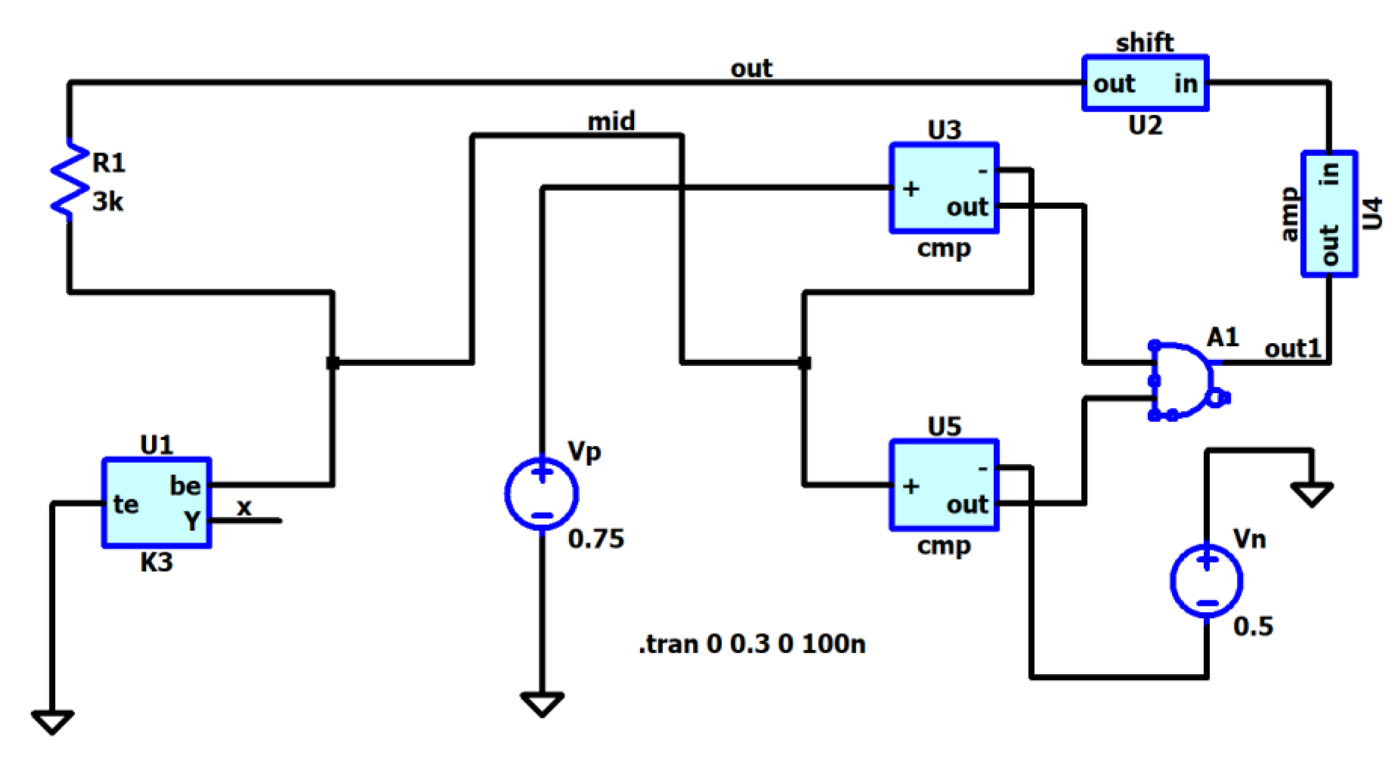
A schematic of a memristor-based reactance-less oscillator is presented in Figure 12 for the description of its structure and the principle of its operation [22]. It contains a series connection of the resistor R1 and the memristor U1: two comparators based on operational amplifiers, two sources of reference voltages (Vp and Vn), a logical AND gate (A1), an amplifier U4, and a shifting module U2.
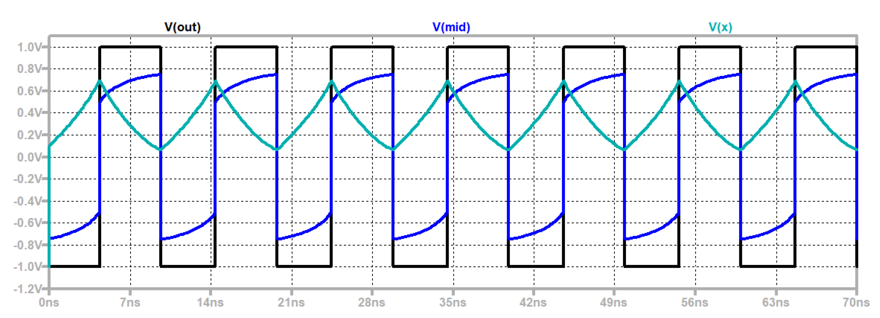
The time diagrams of the signals are presented in Figure 13 for an explanation of the operation of the memristor-based generator.
In the initial moment, the output voltage of the logic gate AND is zero, and the voltage across the voltage divider R1-U1 is equal to -1 V. The metal-oxide memristor U1 is reversely biased, and the voltage across it leads to an increase in the state variable and a decrease in its memristance. Owing to this, the voltage drop across the memristor increases, and when its value is lower than the reference voltage Vp, then the comparator A1 produces a logical unity. The output voltage of the generator jumps to 1 V. Then, the state variable of the memristor decreases, and its memristance increases, leading to the arising voltage drop across the memristor. This follows a new jump of the output signal, which becomes equal to -1. In this way, the considered memristor-based schematic produces rectangular impulses. The state variable changes in a comparatively broad range between 0.1 and 0.7, which corresponds to a soft-switching mode. The frequency of the output signal depends on the switching properties of the applied metal-oxide memristor. In the present case, the Lehtonen-Laiho memristor models, followed by the modified models A11, A12, and A13, represent better-switching properties than the Biolek and Joglekar memristor models.
4.6. Memristor-Based Filters
In this section, several memristor-based passive filters are considered and analyzed in the LTSPICE environment [19,32,33].
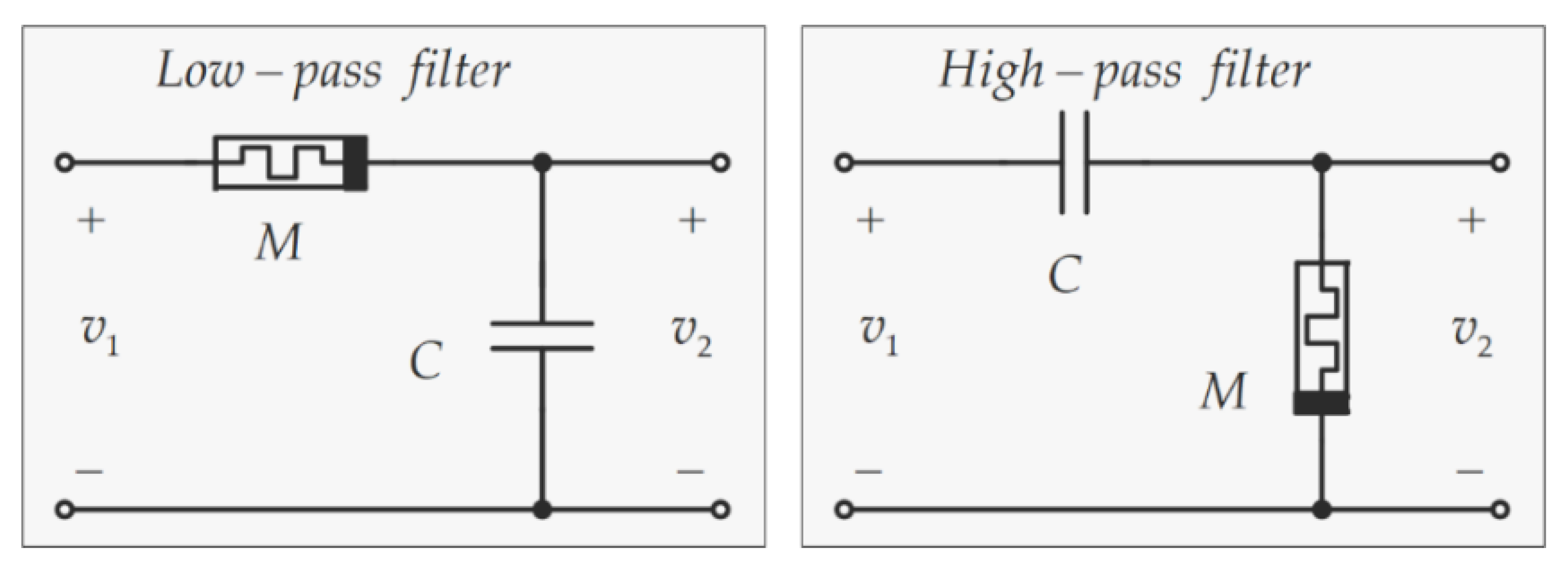
Low-pass and high-pass passive filters, based on memristors and capacitors, are presented in Figure 14 for a description of their structure and operation [19].
The capacitance of C has a value of 1 nF. In the low-pass filter, the capacitor C is connected to the output and shunts it for frequencies higher than the cut-off frequency flow [19,43]:
In the high-pass filter, the memristor M is connected in parallel to the output. The cut-off frequency of the high-pass filter is calculated by a formula similar to formula (11). The cut-off frequencies are changed by the alteration in the memristance M, using positive or negative external voltage pulses with levels that are higher than the memristor activation threshold vthr.
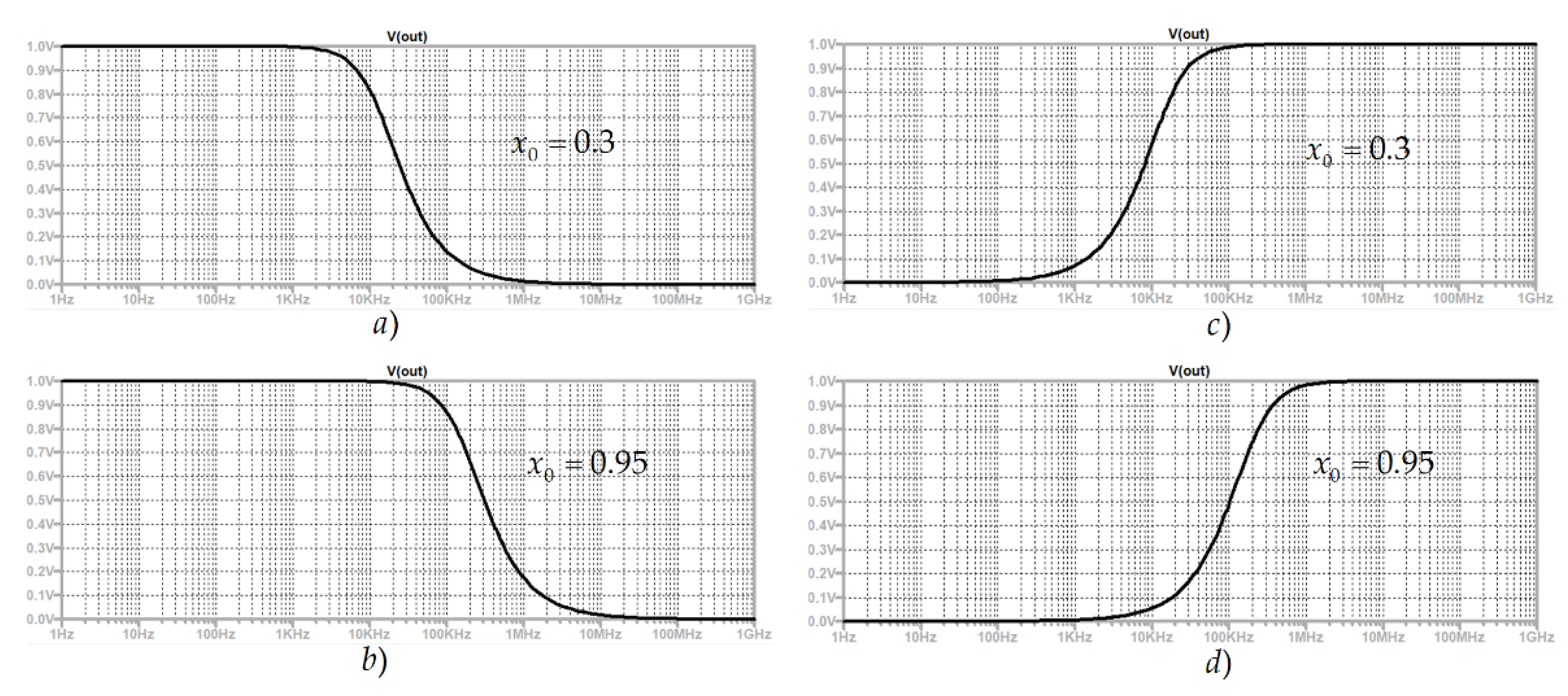
In the considered low-pass and high-pass filters, the memristors operate with signals which have a lower level than their activation thresholds. Memristors behave as linear resistors with a constant value of their resistances. The amplitude-frequency and phase-frequency responses of the low-pass and high-pass filters are presented in Figure 15 for several different values of the memristances to represent the change in the respective cut-off frequencies and the frequency bands.
By increasing the state variable, the respective memristance decreases, and the corresponding cut-off frequency increases. The change in the state variable in the range from zero to unity ensures the alteration of the cut-off frequency from 9.95 kHz to 1.59 MHz.
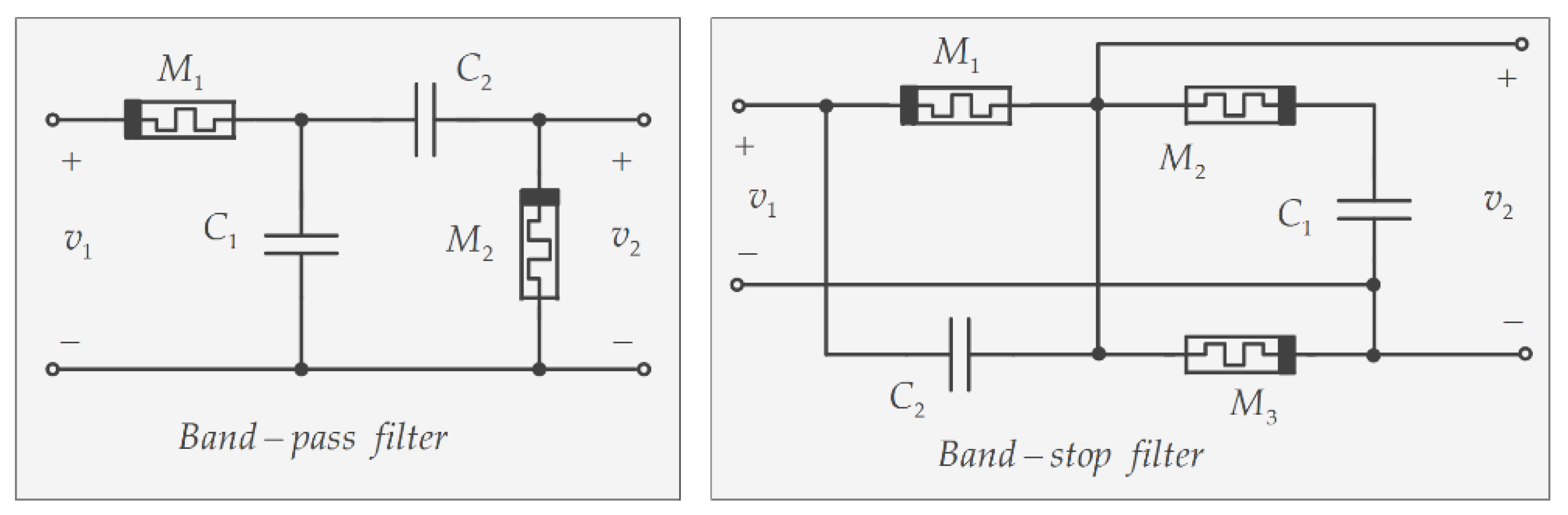
In Figure 16, band-pass and band-stop memristor filters are presented for an explanation of their structure and functioning.
They are based on the previously discussed low-pass and high-pass filtering groups. The band-pass filter is constructed by a cascade connection of low-pass and high-pass filters. The low-pass filter group contains the elements M1 and C1, while the high-pass filter module is made of the components C2 and M2. In this circuit, the cut-off frequency of the low-pass filter flow is higher than those of the high-pass filter—fhigh—so the frequency band of the equivalent band-pass filter is [18,43]:
The band-stop memristor filter is presented in Figure 16 for a further description of its structure and principle of operation. It is based on a parallel connection of low-pass and high-pass filtering groups. The low-pass filtering module is realized by the elements M1 and C1, and the high-pass filter by C2 and M3. The memristor M2 is connected in series to the capacitor C1. It ensures a non-zero level of the output voltage for very high frequencies.
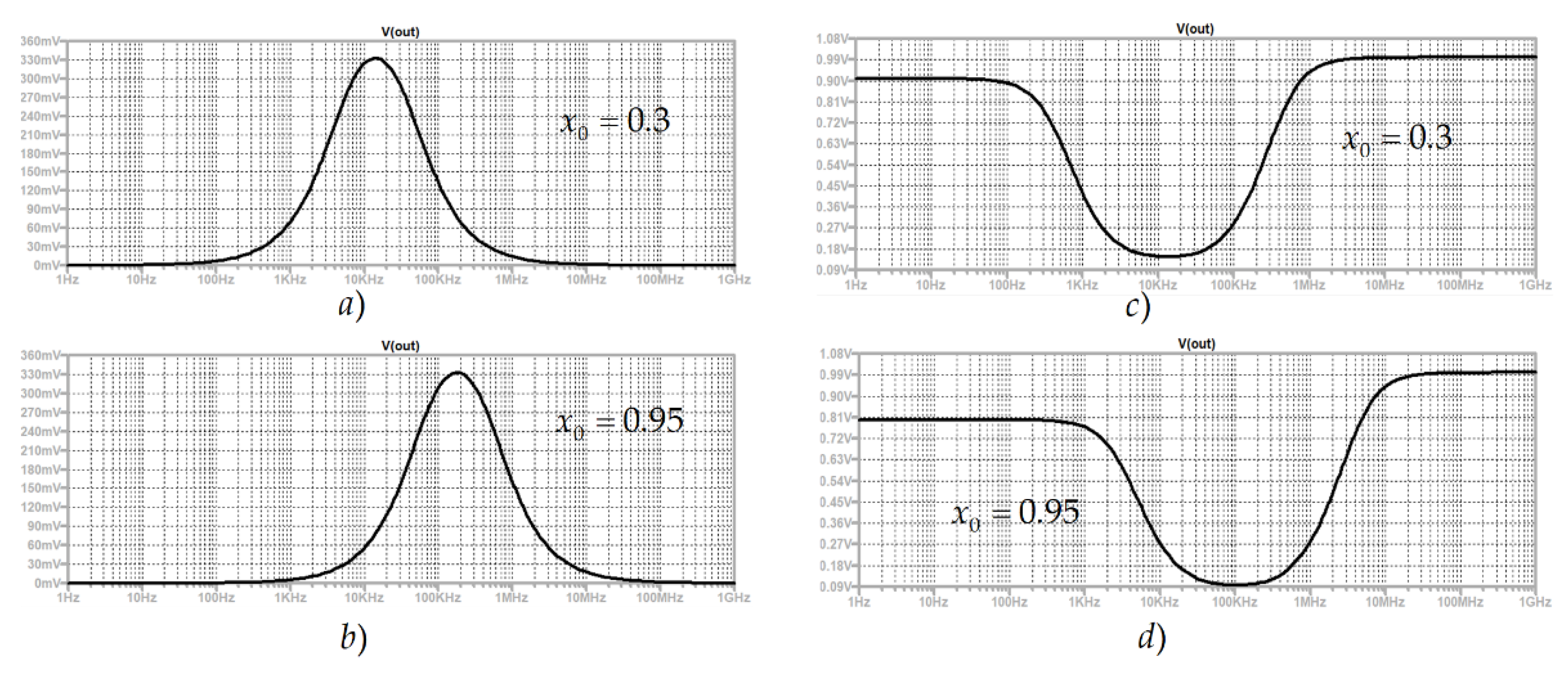
In Figure 17, the amplitude-frequency and phase-frequency responses of the considered band-pass and band-stop filters at different memristance and state variables are presented for a further explanation and description of the filters’ characteristics and properties.
5. A Comparison of the Used Memristor Models
The models of metal-oxide memristor elements, which were applied for the investigation of the discussed memristor-based digital and analog devices, are compared one to another according to their behavior in the electric field and the use of some basic criteria for comparison, including the complexity, operating frequency, simulation time, activation thresholds, RMS error, accuracy, switching properties [6,16]. Some of these criteria are numerically evaluated, while others are introduced by qualitative expressions [3,33,36]. The results are presented in Table 1 for a comparison of the memristor models.
The complexity of a metal-oxide memristor model is proportional to the time needed for a computer simulation. It depends mainly on the number of mathematical operations that are included in the respective model. This measure is introduced rendering to the complexity, and the modified metal-oxide memristor models A11, A13, and A12 are simpler compared to the standard Lehtonen-Laiho memristor model. The modified and improved models A11, A13, and A12 have a high operating frequency and accuracy, very near to that of the classical Lehtonen-Laiho model. Due to their lower complexity, the modified models of A11, A13, and A12 are suitable for the analysis of electronic devices and circuits with a large number of memristors.
The operating frequency of a metal-oxide memristor model depends on its capability to correctly express the alteration of the memristor state variable and the respective memristance proportionally to the voltage signal across the memristor. For models of metal oxide memristors, a low frequency is recognized between 0.5 Hz and 1 kHz, a middle frequency between 1 kHz and 100 kHz, and high frequencies are higher than 100 kHz. The standard Lehtonen-Laiho memristor model has the highest operating frequency, followed by the enhanced and modified memristor models of A11, A13, and A12 and the standard Joglekar and Biolek memristor models.
The simulation time of a metal-oxide memristor model is proportional to the elementary mathematical operations in the equations of the model. In the considered analyses, the classical Joglekar and Biolek memristor models have the lowest simulation time, followed by the modified models A11, A13, and A12 and the standard Lehtonen-Laiho model. Due to this, the Joglekar, Biolek, A11, A13, and A12 have a very high operating speed, followed by the classical Lehtonen-Laiho model.
Memristor models, which include activation thresholds are able to operate in different modes in hard-switching, soft-switching, and as linear resistors when the state variable and the respective memristance have constant values and do not depend on the applied voltage. When the applied signal exceeds the activation threshold, then the state variable changes proportionally to the time integral of the applied voltage.
The root mean square (RMS) error of a memristor model is represented as a square root of the sum of the squared differences between the simulated and the experimental currents of the memristor. In the present case, the classical Lehtonen-Laiho memristor model is able to represent current-voltage characteristics of metal-oxide memristors with a minimal RMS error, followed by the modified models of A11, A13, and A12, and the standard Biolek and Joglekar memristor models.
The accuracy of a memristor model is inversely proportional to the root mean square error. It is expressed using a qualitative comparison according to the previously discussed RMS error. When the RMS error of a memristor model is lower than 4%, the respective accuracy of the model has a high value. If the RMS error of a memristor model is between 4 and 6%, then it has a middle accuracy. A low accuracy is related to an error higher than 6% [33]. The classical Lehtonen-Laiho model has the highest accuracy, followed by the modified memristor models A11, A13, A12, Biolek, and the Joglekar models.
The switching properties of a memristor model are associated with the quick change in the state variable and the corresponding memristance under voltage impulses. The Lehtonen-Laiho memristor model has the best switching properties, followed by the modified models A11, A13, A12, and the standard Biolek model.
6. Discussion
In this work, several memristor-based electronic devices and circuits are discussed and analyzed. Memristor-based non-volatile memory crossbars, a neural network, an amplifier, a reactance-less oscillator, and filters with memristors were analyzed and designed in the LTSPICE environment using several of the mainly applied standard memristor models, together with some modified and improved metal-oxide memristor models. The analysis of the considered memristor-based circuits confirms that the used modified and enhanced metal-oxide memristor models, together with the standard Lehtonen-Laiho model, have better-switching properties than the classical Biolek memristor model. The standard Biolek and Joglekar models and the user-modified metal-oxide memristor models have a faster operation in SPICE due to their simplified expressions. They are successfully applied for the analyses of complex memristor-CMOS electronic circuits.
7. Conclusions
The modified and classical metal-oxide memristor models considered in this work are applied in several memristor-based electronic circuits and devices, including passive and hybrid memory crossbars, a neural network, filters, an amplifier, and a generator, while the analyses and simulations are conducted in LTSPICE environment. The operation of the modified memristor models is compared to those of the classical Joglekar, Biolek, and Lehtonen-Laiho models, according to their behavior in the electric field and several significant criteria for comparison, including complexity, operating frequency, switching properties, simulation time, accuracy and the use of activation thresholds. The modified metal-oxide memristor models and the classical Lehtonen-Laiho model have better-switching properties than the standard Strukov-Williams, Joglekar, and Biolek models and are efficiently applicable in different complex electronic circuits owing to their simplified expressions and good accuracy. The used flat and differentiable step-like sigmoidal function, the respective window functions based on the sigmoidal function, and the application of LTSPICE software partially prevent convergence issues during the analyses. The design of memristor-based electronic schemes in the LTSPICE environment, using modified metal-oxide memristor models, is an important stage in the realization of improved, high-density, and low-power integrated circuits.
Funding
This research received no external funding.
Institutional Review Board Statement
Not applicable.
Informed Consent Statement
Not applicable.
Data Availability Statement
Not applicable.
Conflicts of Interest
The authors declare no conflict of interest.
References
- Strukov, D.B.; Snider, G.S.; Stewart, D.R.; Williams, R.S. The missing memristor found. Nature 2008, 453, 80–83. [Google Scholar] [CrossRef] [PubMed]
- Chua, L. Memristor-The missing circuit element. IEEE Trans. Circuit Theory 1971, 18, 507–519. [Google Scholar] [CrossRef]
- Ascoli, A.; Corinto, F.; Senger, V.; Tetzlaff, R. Memristor Model Comparison. IEEE Circuits Syst. Mag. 2013, 13, 89–105. [Google Scholar] [CrossRef]
- Joglekar, Y.N.; Wolf, S.J. The elusive memristor: Properties of basic electrical circuits. Eur. J. Phys. 2009, 30, 661. [Google Scholar] [CrossRef] [Green Version]
- Corinto, F.; Ascoli, A. A Boundary Condition-Based Approach to the Modeling of Memristor Nanostructures. IEEE Trans. Circuits Syst. 2012, 59, 2713–2727. [Google Scholar] [CrossRef]
- Amer, S.; Sayyaparaju, S.; Rose, G.S.; Beckmann, K.; Cady, N.C. A practical hafnium-oxide memristor model suitable for circuit design and simulation. In Proceedings of the 2017 IEEE International Symposium on Circuits and Systems (ISCAS), Baltimore, MD, USA, 28–31 May 2017; pp. 1–4. [Google Scholar]
- Strachan, J.P.; Torrezan, A.C.; Miao, F.; Pickett, M.D.; Yang, J.J.; Yi, W.; Medeiros-Ribeiro, G.; Williams, R.S. State dynamics and modeling of tantalum oxide memristors. IEEE Trans. Electron Devices 2013, 60, 2194–2202. [Google Scholar] [CrossRef]
- Kumar, S.; Wang, Z.; Davila, N.; Kumari, N.; Norris, K.J.; Huang, X.; Strachan, J.P.; Vine, D.; Kilcoyne, A.L.; Nishi, Y.; et al. Physical origins of current and temperature controlled negative differential resistances in NbO2. Nat. Commun. 2017, 8, 658. [Google Scholar] [CrossRef] [Green Version]
- Chen, Y.; Liu, G.; Wang, C.; Zhang, W.; Li, R.-W.; Wang, L. Polymer memristor for information storage and neuromorphic applications. Mater. Horiz. 2014, 1, 489–506. [Google Scholar] [CrossRef]
- Chanthbouala, A.; Garcia, V.; Cherifi, R.O.; Bouzehouane, K.; Fusil, S.; Moya, X.; Xavier, S.; Yamada, H.; Deranlot, C.; Mathur, N.D.; et al. A ferroelectric memristor. Nat. Mater. 2012, 11, 860–864. [Google Scholar] [CrossRef] [Green Version]
- Wang, X.; Chen, Y.; Xi, H.; Li, H.; Dimitrov, D. Spintronic Memristor through Spin-Torque-Induced Magnetization Motion. IEEE Electron Device Lett. 2009, 30, 294–297. [Google Scholar] [CrossRef]
- Romero, F.J.; Toral-Lopez, A.; Ohata, A.; Morales, D.P.; Ruiz, F.G.; Godoy, A.; Rodriguez, N. Laser-Fabricated reduced graphene oxide memristors. Nanomaterials 2019, 9, 897. [Google Scholar] [CrossRef] [PubMed] [Green Version]
- Mohammad, B.; Jaoude, M.; Kumar, V.; Al Homouz, D.; Nahla Heba Abu Al-Qutayri, M.; Christoforou, N. State of the art of metal oxide memristor devices. Nanotech. Rev. 2016, 5, 311–329. [Google Scholar] [CrossRef]
- Zhang, Y.; Wang, X.; Friedman, E.G. Memristor-Based Circuit Design for Multilayer Neural Networks. IEEE Trans. Circuits Syst. I Regul. Pap. 2018, 65, 677–686. [Google Scholar] [CrossRef]
- Mladenov, V.; Kirilov, S. A Modified Metal Oxide Memristor Model. In Proceedings of the 2022 11th International Conference on Modern Circuits and Systems Technologies (MOCAST), Bremen, Germany, 8–10 June 2022; pp. 1–4. [Google Scholar] [CrossRef]
- Yilmaz, Y.; Mazumder, P. A Drift-Tolerant Read/Write Scheme for Multi-Level Memristor Memory. IEEE Trans. Nanotechnol. 2017, 16, 1016–1027. [Google Scholar] [CrossRef]
- Mladenov, V.; Kirilov, S. An Improved Model for Metal Oxide-Based Memristors and Application in Memory Crossbars. In Proceedings of the 18th International Conference on Synthesis, Modeling, Analysis and Simulation Methods and Applications to Circuit Design (SMACD), Villasimius, Italy, 12–15 June 2022; pp. 1–4. [Google Scholar] [CrossRef]
- Ascoli, A.; Tetzlaff, R.; Corinto, F.; Mirchev, M.; Gilli, M. Memristor-based filtering applications. In Proceedings of the 2013 14th Latin American Test Workshop-LATW, Cordoba, Argentina, 3–5 April 2013; pp. 1–6. [Google Scholar]
- Mladenov, V.; Kirilov, S.; Zaykov, I. A General Model for Metal Oxide-Based Memristors and Application in Filters. In Proceedings of the 2022 11th International Conference on Modern Circuits and Systems Technologies (MOCAST), Bremen, Germany, 8–10 June 2022; pp. 1–4. [Google Scholar] [CrossRef]
- Singh, C.P.; Pandey, S.K. An efficient and flexible window function for a memristor model and its analog circuit application. J. Comput. Electron. 2022, 21, 1425–1433. [Google Scholar] [CrossRef]
- Ascoli, A.; Weiher, M.; Herzig, M.; Slesazeck, S.; Mikolajick, T.; Tetzlaff, R. Graph Coloring via Locally-Active Memristor Oscillatory Networks. J. Low Power Electron. Appl. 2022, 12, 22. [Google Scholar] [CrossRef]
- Zidan, M.A.; Omran, H.; Radwan, A.G.; Salama, K.N. Memristor-based reactance-less oscillator. Electron. Lett. 2011, 47, 1220–1221. [Google Scholar] [CrossRef]
- Kvatinsky, S.; Wald, N.; Satat, G.; Kolodny, A.; Weiser, U.C.; Friedman, E.G. MRL—Memristor ratioed logic. In Proceedings of the 2012 13th International Workshop on Cellular Nanoscale Networks and their Applications, Turin, Italy, 29–31 August 2012; pp. 1–6. [Google Scholar]
- Siemon, A.; Menzel, S.; Waser, R.; Linn, E. A complementary resistive switch-based crossbar array adder. IEEE J. Emerg. Sel. Top. Circuits Syst. 2015, 5, 64–74. [Google Scholar] [CrossRef] [Green Version]
- Wiefels, S.; Bengel, C.; Kopperberg, N.; Zhang, K.; Waser, R.; Menzel, S. HRS instability in oxide-based bipolar resistive switching cells. IEEE Trans. Electron Devices 2020, 67, 4208–4215. [Google Scholar] [CrossRef]
- Li, Y.; Kvatinsky, S.; Kornblum, L. Harnessing conductive oxide interfaces for resistive random-access memories. Front. Phys. 2021, 9, 772238. [Google Scholar] [CrossRef]
- Wang, W.; Bricalli, A.; Laudato, M.; Ambrosi, E.; Covi, E.; Ielmini, D. Physics-based modeling of volatile resistive switching memory (RRAM) for crosspoint selector and neuromorphic computing. In Proceedings of the IEEE International Electron Devices Meeting (IEDM), San Francisco, CA, USA, 1–5 December 2018; pp. 40.3.1–40.3.4. [Google Scholar] [CrossRef] [Green Version]
- Wang, W.; Song, W.; Yao, P.; Li, Y.; Van Nostrand, J.; Qiu, Q.; Ielmini, D.; Yang, J.J. Integration and co-design of memristive devices and algorithms for artificial intelligence. Iscience 2020, 23, 101809. [Google Scholar] [CrossRef] [PubMed]
- Jiang, Z.; Yu, S.; Wu, Y.; Engel, J.H.; Guan, X.; Wong, H.S.P. Verilog-A compact model for oxide-based resistive random access memory (RRAM). In Proceedings of the 2014 International Conference on Simulation of Semiconductor Processes and Devices (SISPAD), Yokohama, Japan, 9–11 September 2014; pp. 41–44. [Google Scholar]
- Ambrogio, S.; Balatti, S.; Gilmer, D.C.; Ielmini, D. Analytical Modeling of Oxide-Based Bipolar Resistive Memories and Complementary Resistive Switches. IEEE Trans. Electron Devices 2014, 61, 2378–2386. [Google Scholar] [CrossRef] [Green Version]
- Mladenov, V. Advanced Memristor Modeling—Memristor Circuits and Networks; MDPI: Basel, Switzerland, 2019; 172p, ISBN 978-3-03897-104-7. [Google Scholar]
- May, C. Passive Circuit Analysis with LTspice®®—An Interactive Approach; Springer Nature: Cham, Switzerland, 2020; p. 763. ISBN 978-3-030-38304-6. [Google Scholar] [CrossRef]
- Mladenov, V. A Unified and Open LTSPICE Memristor Model Library. Electronics 2021, 10, 1594. [Google Scholar] [CrossRef]
- Biolek, Z.; Biolek, D.; Biolkova, V. SPICE Model of Memristor with Nonlinear Dopant Drift. Radioengineering 2009, 18, 210–214. [Google Scholar]
- Lehtonen, E.; Laiho, M. CNN using memristors for neighborhood connections. In Proceedings of the 2010 12th International Workshop on Cellular Nanoscale Networks and their Applications (CNNA 2010), Berkeley, CA, USA, 3–5 February 2010; pp. 1–4. [Google Scholar]
- Ascoli, A.; Tetzlaff, R.; Biolek, Z.; Kolka, Z.; Biolkova, V.; Biolek, D. The Art of Finding Accurate Memristor Model Solutions. IEEE J. Emerg. Sel. Top. Circuits Syst. 2015, 5, 133–142. [Google Scholar] [CrossRef]
- Strukov, D.; Williams, S. Exponential ionic drift: Fast switching and low volatility of thin-film memristors. Appl. Phys. A 2009, 94, 515–519. [Google Scholar] [CrossRef]
- Lanza, M.; Waser, R.; Ielmini, D.; Yang, J.J.; Goux, L.; Suñe, J.; Kenyon, A.J.; Mehonic, A.; Spiga, S.; Rana, V.; et al. Standards for the characterization of endurance in resistive switching devices. ACS Nano 2021, 15, 17214–17231. [Google Scholar] [CrossRef] [PubMed]
- Guseinov, D.V.; Matyushkin, I.V.; Chernyaev, N.V.; Mikhaylov, A.N.; Pershin, Y.V. Capacitive effects can make memristors chaotic. Chaos, Solitons Fractals 2021, 144, 110699. [Google Scholar] [CrossRef]
- Yang, Y.; Lee, S. Circuit Systems with MATLAB and PSpice; John Wiley & Sons: Hoboken, NJ, USA, 2008; ISBN 978-04-7082-240-1. [Google Scholar]
- Carrillo, M.; González José, M. A new approach to modelling sigmoidal curves. Technol. Forecast. Soc. Chang. 2002, 69, 233–241. [Google Scholar] [CrossRef]
- Chen, S.; Billings, S.; Luo, W. Orthogonal least squares methods and their application to non-linear system identification. Int. J. Control. 1989, 50, 1873–1896. [Google Scholar] [CrossRef]
- Winder, S. Analog and Digital Filter Design; Elsevier Science: Alpharetta, GA, USA, 2002; ISBN 0-7506-7547-0. [Google Scholar]
Figure 1.
(a) Parameter trajectories obtained during the memristor model parameters estimation; (b) Time diagrams of the memristor voltage, experimental, and simulated currents according the modified model A13 and the standard Lehtonen-Laiho model, denoted by K5, and the corresponding current–voltage relationships.

Figure 2.
An equivalent schematic of a memristor model in the LTSPICE environment.

Figure 3.
A passive memristor memory crossbar.

Figure 4.
Time graphs of the voltage and state variable during writing and erasing information in a passive memristor crossbar, according to the described standard models–K2 (Joglekar), K3 (Biolek), K5 (Lehtonen-Laiho), and modified memristor models A11, A12, and A13.
Figure 4.
Time graphs of the voltage and state variable during writing and erasing information in a passive memristor crossbar, according to the described standard models–K2 (Joglekar), K3 (Biolek), K5 (Lehtonen-Laiho), and modified memristor models A11, A12, and A13.

Figure 5.
A hybrid memristor memory crossbar.

Figure 6.
Time diagrams of the memristor voltage, memristance, and state variables according to the applied modified and standard metal-oxide memristor models.
Figure 6.
Time diagrams of the memristor voltage, memristance, and state variables according to the applied modified and standard metal-oxide memristor models.

Figure 7.
A memristor-based neural network.

Figure 8.
A schematic of the used memristor synapse.

Figure 9.
(a) Time diagrams of the input and output signals of the memristor neural network; (b) Diagrams of the input signal of the synaptic circuit and the corresponding alteration of the weight.
Figure 9.
(a) Time diagrams of the input and output signals of the memristor neural network; (b) Diagrams of the input signal of the synaptic circuit and the corresponding alteration of the weight.

Figure 10.
A memristor-based differential amplifier.

Figure 11.
Time diagrams of the input and output signals of the memristor-based amplifier presented in Figure 10.
Figure 11.
Time diagrams of the input and output signals of the memristor-based amplifier presented in Figure 10.

Figure 12.
A memristor-based reactance-less generator.

Figure 13.
Time diagrams of the output voltage of the generator, the state variable, and memristor voltage according to the considered standard and modified memristor models A11, A12, and A13.
Figure 13.
Time diagrams of the output voltage of the generator, the state variable, and memristor voltage according to the considered standard and modified memristor models A11, A12, and A13.

Figure 14.
Low-pass and high-pass memristor-based filters.

Figure 15.
(a) Amplitude-frequency response (AFR) of a low-pass filter for x0 = 0.3: (b) AFR of a low-pass filter for x0 = 0.95; (c) AFR for the high-pass filter for x0 = 0.3; (d) AFR for the high-pass filter for x0 = 0.95.
Figure 15.
(a) Amplitude-frequency response (AFR) of a low-pass filter for x0 = 0.3: (b) AFR of a low-pass filter for x0 = 0.95; (c) AFR for the high-pass filter for x0 = 0.3; (d) AFR for the high-pass filter for x0 = 0.95.

Figure 16.
Band-pass and band-stop memristor-based filters.

Figure 17.
(a) Amplitude-frequency response (AFR) of a band-pass filter for x0 = 0.3: (b) AFR of a band-pass filter for x0 = 0.95; (c) AFR for the band-stop filter for x0 = 0.3; (d) AFR for the band-stop filter for x0 = 0.95.
Figure 17.
(a) Amplitude-frequency response (AFR) of a band-pass filter for x0 = 0.3: (b) AFR of a band-pass filter for x0 = 0.95; (c) AFR for the band-stop filter for x0 = 0.3; (d) AFR for the band-stop filter for x0 = 0.95.


Table 1.
A comparison of the applied standard and modified memristor models according to several important criteria.
Table 1.
A comparison of the applied standard and modified memristor models according to several important criteria.
| Model | Joglekar | Biolek | Lehtonen-Laiho | A11 | A12 | A13 |
|---|---|---|---|---|---|---|
| Complexity | low | low | high | low | low | low |
| Operating Frequency | low | middle | high | high | high | high |
| Simulation Time,ms | 16.42 | 16.74 | 18.65 | 17.23 | 17.34 | 17.28 |
| Activation Thresholds | no | no | no | yes | yes | yes |
| RMS Error | 6.24 | 5.87 | 3.63 | 3.75 | 3.68 | 3.72 |
| Accuracy | low | middle | high | high | high | high |
| Switching Properties | middle | middle | good | good | good | good |
Disclaimer/Publisher’s Note: The statements, opinions and data contained in all publications are solely those of the individual author(s) and contributor(s) and not of MDPI and/or the editor(s). MDPI and/or the editor(s) disclaim responsibility for any injury to people or property resulting from any ideas, methods, instructions or products referred to in the content. |
© 2023 by the author. Licensee MDPI, Basel, Switzerland. This article is an open access article distributed under the terms and conditions of the Creative Commons Attribution (CC BY) license (https://creativecommons.org/licenses/by/4.0/).
Share and Cite
MDPI and ACS Style
Mladenov, V. Application and Analysis of Modified Metal-Oxide Memristor Models in Electronic Devices. Technologies 2023, 11, 20. https://doi.org/10.3390/technologies11010020
AMA Style
Mladenov V. Application and Analysis of Modified Metal-Oxide Memristor Models in Electronic Devices. Technologies. 2023; 11(1):20. https://doi.org/10.3390/technologies11010020
Chicago/Turabian StyleMladenov, Valeri. 2023. "Application and Analysis of Modified Metal-Oxide Memristor Models in Electronic Devices" Technologies 11, no. 1: 20. https://doi.org/10.3390/technologies11010020
Note that from the first issue of 2016, this journal uses article numbers instead of page numbers. See further details here.