

Cost-Effective 3D Printing of Silicone Structures Using an Advanced Intra-Layer Curing Approach

1
SMART Infrastructure Facility, Engineering and Information Sciences, University of Wollongong, Wollongong, NSW 2522, Australia
2
Faculty of Pharmacy and Pharmaceutical Sciences, Monash University, Clayton, VIC 3168, Australia
*
Author to whom correspondence should be addressed.
Technologies 2023, 11(6), 179; https://doi.org/10.3390/technologies11060179
Submission received: 23 October 2023
/
Revised: 23 November 2023
/
Accepted: 8 December 2023
/
Published: 12 December 2023
(This article belongs to the Special Issue 3D Printing Technologies II)
Abstract
:We present an advanced, low-cost 3D printing system capable of fabricating intricate silicone structures using commercially available off-the-shelf materials. Our system used a custom-designed, motorised syringe pump with a driving lead screw and excellent control of material extrusion to accommodate the high viscosity of silicone printing ink, which is composed of polydimethylsiloxane (PDMS), diluent, and a photo-initiator (LAP). We modified an open-source desktop 3D printer to mount the syringe pump and programmed it to deposit controlled intricate patterns in a layer-by-layer fashion. To ensure the structural integrity of the printed objects, we introduced an intra-layer curing approach that fused the deposited layers using a custom-built UV curing system. Our experiments demonstrated the successful fabrication of silicone structures at different infill percentages, with excellent resolution and mechanical properties. Our low-cost solution (costing less than USD 1000 and requiring no specialised facilities or equipment) shows great promise for practical applications in areas such as micro-fluidics, prosthesis, and biomedical engineering based on our initial findings of 300 μ width channels (with excellent scope for smaller channels where desirable) and tunable structural properties. Our work represents a significant advance in low-cost desktop 3D printing capabilities, and we anticipate that it could have a broad impact on the field by providing these capabilities to scholars without the means to purchase expensive fabrication systems.
1. Introduction
The revolutionary technology of additive manufacturing, also known as 3D printing, has emerged as a disruptive force with far-reaching implications [1,2,3,4]. Its profound impact has been observed in various fields, such as tissue engineering [5,6], micro-fluidics [7,8], fashion and textiles [9,10], and even patent law [11], to name a few. The unparalleled ability of this technique to rapidly fabricate highly customised and intricate parts without the need for costly and specialised facilities operated by skilled personnel distinguishes it from conventional manufacturing methods. Crucial to this capability is the material’s compatibility with the available 3D printing technologies, or alternatively, the adaptation of the fabrication process to suit the material [12].
PDMS, a silicone-based organic polymer, has attracted considerable interest in the realm of 3D printing. With its advantageous properties including biocompatibility, optical transparency, thermal stability, non-toxicity, non-flammability, and cost-effectiveness, PDMS is widely used in various industries such as electronics, textiles, household cookware, dentistry, and medicine [13,14,15,16]. Despite its broad range of applications, traditional manufacturing techniques for silicone-based parts such as injection moulding are prohibitively expensive due to the high cost of producing moulds, which hinders the production of prototypes, bio-models, and small batches of complex geometries. This limitation underscores the importance of 3D printing technology in the fabrication of complex, customised parts [17,18].
PDMS (silicone) structures have traditionally been manufactured using moulding. However, recent advances in additive manufacturing technologies have spurred interest in exploring the advantages of direct printing over traditional moulding techniques. The benefits of direct printing have been demonstrated in various studies across different domains [19,20,21]. For instance, Fuenmayor et al. [22] compared fused filament fabrication (FFF) to direct compression (DC) and injection moulding (IM) for the production of oral tablets, highlighting the potential of FFF for efficient and personalised tablet manufacturing. Yirmibesoglu et al. [23] showcased the capabilities of direct 3D printing for soft elastomer robots, demonstrating that 3D printed robots could match or exceed the performance of their moulded counterparts while offering enhanced reliability and robustness. Additionally, Riedle et al. [24] compared moulding techniques and direct 3D printing for silicone models of anatomical soft tissue structures, emphasising the suitability of 3D printing for complex designs. These studies collectively underscore the advantages of direct printing, including precision, adaptability, and the ability to produce intricate structures that may be challenging or impossible with traditional moulding methods.
Duoss et al. [25] were the first to report on the direct 3D printing of silicone using micro-extrusion, employing a 610 diameter nozzle and a high-end linear stage system (Aerotech) with thermal curing and pneumatic pressure. Kolesky et al. [26] used a multi-ink approach featuring PDMS micro-extrusion and a high-precision stage (ABG 10000, Aerotech) for vascular tissue constructs. Coulter et al. [27] employed spraying and extrusion-based direct ink writing techniques to print a silicone-based heart valve. Other studies have explored applications in drug delivery [28], sensing [29,30], actuators [31], soft robotics [23], electronics [32], foams [33], cell adhesion [34], and other areas. However, these studies were limited by the use of high-end industrial-grade equipment and specialised facilities, hindering their wider applicability, as noted by He et al. [35]. This has limited the ability of those without access to such facilities to explore novel ideas and approaches and therefore progress the field [36]. To address this, it is necessary to overcome the challenges associated with translating these capabilities into cost-effective systems. This has been successfully achieved before with open-source approaches and FDM thermoplastic printers [37].
In the past, thermoplastic FDM 3D printers [38] were very expensive, costing over USD 10,000 [1,39,40]. However, due to open-source designs and mass production, the cost dropped significantly to around USD 500 by 2016 [37]. As interest in 3D printing expanded, there was a corresponding demand for additional materials. Typically, this was left to industrial entities, but there are a few exceptions where low-cost 3D printers were proposed for metals [41,42], ceramics [43], and bio-related materials [44,45,46].
Although PDMS printing using high-end technology has been studied previously, little attention has been given to the challenges of printing this material at a low cost and without specialised facilities. One exception is an approach proposed by Calcagnile et al. [47], which involved developing Na–CMC/PDMS composite filaments that could be printed using a conventional FDM thermoplastic printer. This method offers scope for the low-cost direct printing of PDMS gels to form structures.
The objective of this investigation was to develop a 3D printer that is both affordable (costing less than USD 1000) and capable of producing 3D structures via a proposed micro-extrusion and intra-layer photo-cross-linking technique. To optimise the PDMS material for micro-extrusion, its viscosity was adjusted through dilution, and the structural integrity was ensured through a photo-initiator. These data were then used to inform the printer design and fabrication of 3D PDMS structures. The printed structures, produced using open-source components at room temperature and at a low cost, were examined via optical microscopy to explore various infill densities.
2. Experiments
2.1. Materials
The preparation of PDMS for material extrusion printing in this study involved several steps. First, UV-curable liquid silicone rubbers (LSRs) (Silopren UV LSR 2030, Momentive) were mixed with a catalyst in a 100:2 ratio (base:catalyst = 100:2). Next, a silicon-based diluent (Silicone diluent, Barnes, Australia) was added to the mixture at a concentration of 10%. The three components were then processed using a planetary centrifugal mixer (THINKY Mixer ARE-310) for 1 h at 2000 rpm to ensure homogeneity.
To examine the effect of cross-linking on the material, a UV LED (365 nm, LedEngin Inc, LZ1-10UV00-0000) was positioned beneath the quartz base of a rheometer (Anton Paar MCR 301, Physica), allowing for irradiation during analysis. After 1 min to establish a baseline, the UV system was powered on to investigate changes with constant irradiance. Figure 1 illustrates the measurements over time, showing an increasing trend in the storage modulus and characterised by an excellent fit to the Gompertz model (R = 0.999). This informed our decision to use an irradiance time of 3 min, i.e., after initial polymerisation (to support successive print layers) and before full polymerisation (preventing layers from adhering completely). As subsequent layers were irradiated, the transparency of the material allowed for further polymerisation in the previous layer, supporting additional weight imposed by subsequent layers.
2.2. Fabrication System Design
2.2.1. 3D Printer Design
The design of the printer, generated using open-source 3D CAD software (FreeCAD, 1.8.4), is shown in Figure 2. The 3D Cartesian movement was achieved through the foundation of an open-source 3D printer (ME2, Me3D Pty Ltd., North Wollongong, NSW, Australia), with modifications made to remove the heated extrusion system and enhance the z-axis [44,46]. The print base was developed with a holder specifically designed to fit a standard petri dish, serving as a clean print base solution. The support was attached to the mount using three retention screws with intermediary springs for print levelling adjustments. The e-axis facilitated the PDMS extrusion mechanism, driven by a high-torque output and holding-current stepper motor (Nema 17, 2.5 A, 1.8/Step, RobotDigg 42HS48-2504). To support this, a strong frame (RobotDigg 100-WL-81) featuring a hardened-steel MGN12 linear rail was selected. These components were integrated with 3D printed adjustments (produced using a uPrint Plus, Dimension, Stratasys) to create a robust syringe pump capable of accommodating 10 mL disposable syringes. The curing of the material was achieved through a high-power LED module (365 nm, LedEngin Inc., San Jose, CA, USA, LZ1-10UV00-0000), which required a heat sink (Aavid Thermalloy, 6238PB-MT5) to address the driver’s temperature increase during operation. The module was mounted on a 3D printed arm at a specific height, providing the same irradiance intensity as that of the characterisation instrumentation (which is discussed later).
2.2.2. Control System
Figure 3 depicts the crucial elements responsible for controlling the dynamics of the fabrication system. The central board, an Ultimaker 1.5.7, provided connections to all peripherals. The x-, y-, and z-axis motors, as shown in Figure 2, were powered by high-performing stepper motor drivers (Pololu, A4988) to enable movement and a holding current. The extrusion system’s stepper motor, which required a higher current, was powered by a separate stepper motor (RobotDigg, TMC2100), with micro-stepping (n = 16) enabled for all motor drivers. A high-current DC–DC step-down regulator (Duinotech, XC-4514) regulated the power to the curing system, which was controlled via a standard input–output (IO) pin from the central board through a pull-up resistor arrangement. This supplied 0.7 A to the LED, resulting in a radiant flux of 1200 mW. The irradiance was measured to be 25 mW.cm at a distance of 5 cm from the sample using a light metre (Lumen Dynamics Omnicure LM2011/LS100 LED Light Meter System).
The central control system was constructed using an Arduino Mega 2560 micro-controller, which governed the connected peripherals as per its programmed instructions. To interface with the central board, the micro-controller was flashed with open-source firmware (Marlin 1.1) and configured according to the manufacturer’s standard axis steps-per-mm settings. Subsequently, custom M-codes were developed to enable the power control of the LED, and the open-source software MatterControl 1.7.5 was installed on a Windows-based PC to facilitate printer control via a USB. Communication between the application and firmware on the logic control board was established through the transmission of a standard G-code. Extruder calibration was performed post-installation, as discussed later.
2.3. PDMS Structures
2.3.1. Preparation/Setup
Before commencing printing, it was essential to ensure the optimal conditions were met to achieve successful prints. Firstly, the print bed was levelled using the levelling screws as depicted in Figure 2. Next, a standard grid pattern was set up using the printing control software to explore various infill volumes, with four in total in steps of 25%. A grid size of 20 × 20 mm was selected to ensure compatibility with the characterisation instrument utilised for compression tests of the printed structures, which will be discussed below. Once the printing parameters were established, an open-source third-party application (Slic3r) was employed to convert the 3D virtual grid into G-code. A post-processing script was applied to the G-code to enable switching from extrusion to photo-initiation at the conclusion of each deposited layer. This helped to partially cure the top layer to support subsequent layers while simultaneously curing the preceding layers. During printing, the 3D printing software handled the timing and communication of the G-code to the printer. It should be noted that the structures were printed in an environmentally controlled room at a temperature of 20 °C.
2.3.2. Printing Process
After loading the prepared material into a 10 mL syringe, the printer initiated the extrusion of a skirt, which involved extruding a single line 20 mm away from the main structure to ensure the proper priming of the material. Subsequently, the printer executed the repeated cycle of events illustrated in the flow diagram in Figure 4 and based on the following processes until N layers were produced, with the printing parameters listed in Table 1 (please note that, in a similar manner to that stated by Gharaie et al. [48], these parameters were determined empirically, i.e., by maximising the motorised force output and analysing the extruded quality, in addition to the infill percentage (discussed later)):
- Print one layer using a rectilinear pattern [49];
- Stop XYZ movement and retract the extruder to stop the material extrusion;
- Increase Z so that the tip is above the height of the petri dish;
- Move the print base (via the y-axis) to beneath the LED for curing;
- Lower Z so that the distance between the layer and the LED is 5 cm;
- Turn on the LED and irradiate the layer (3 min);
- Turn off the LED and increase Z;
- Move the print base (via the y-axis) back to the printing position;
- Move Z to the next layer height.
3. Results and Discussion
3.1. Extrusion System and Calibration
Early in the project, attempts were made to utilise a pneumatic regulator (IEI Iwashita, AD 3000C), along with a pressurised air supply and a well-established 3D printer (KIMM SPS1000 Bioplotter). However, this approach encountered challenges as the silicone material did not extrude consistently, and adjusting the pressure resulted in either no material flow or excessive extrusion. This difficulty was attributed to factors such as the non-Newtonian nature of the material, coupled with the syringe tip diameter. The need for fine control over the extrusion process prompted the exploration of alternative solutions. Consequently, a motorised extruder, specifically a syringe pump, was developed. The superior extrusion control offered by this system is evident in Figure 5 (bottom right), showing consistent flow. This shift in approach marked a crucial step in achieving the precision required for our project goals.
In Figure 6, we present the outcomes of our calibration procedure for the extrusion mechanism, which entailed employing a robust syringe pump. Our analysis using a steps-per-mm ratio (Steps.mm) of 1000 (estimated observation) led to a slope (m) of 1.62, as determined via linear regression. Inverting this slope and multiplying it by 1000 yielded a mathematically corrected slope of 1.0, which was corroborated by our second calibration and the resulting linear regression model. This was evident from the regression analysis (red line) applied to the second calibration, where a ratio of 617.29 Steps.mm accurately reflects the movement of the syringe.
To clarify the calibration process, we extended the syringe pump carriage by 1000 steps, a rough estimation for 1 mm. Subsequently, we conducted a calibration for a programmed 11 cm distance. The linear regression yielded a slope of 1.62. Using this value, we adjusted the steps-per-mm ratio to 617. After a second calibration, this yielded a slope of 1, demonstrating that the programmed/software distance was precisely aligned with the measured distance. This ensured accurate material extrusion distances, resulting in desirable volumes and speeds for essential control. Based on the syringe’s geometry, we calculated a linear resolution of L.Step, corresponding to L.Step.
3.2. Developed Printer
In Figure 5, we present our custom fabrication system, which was detailed in Section 2.2.1 and was based on the design shown in Figure 2 along with the major components for developing the printer in Table 2. We provide detailed views of both the extrusion and photo-initiation stages during the fabrication of a structure for the sake of clarity. Additionally, we showcase the extrusion mechanism, which featured a steady stream of 10 wt.% PDMS material being extruded and collected in a container. Using this setup, we examined various tip sizes to achieve a constant flow of PDMS with 10 wt.% diluent. Our investigations revealed that SmoothFlow tapered tips from Nordson outperformed standard tips for the extrusion of this material, which was most likely due to their conical shape. Furthermore, we examined tip diameters ranging from 0.2 to 1.60 mm. While the 200 tip successfully extruded the material for a short period, it resulted in the overheating of the motor driver. For safety purposes, we selected the 580 tip to achieve a constant flow rate throughout the printing process. Active and passive heat dissipation techniques such as peltiers, fans, and/or larger heatsinks could be employed to dissipate the heat generated by the extrusion process if a smaller nozzle is required. Using this tip size, we incrementally increased the applied feed rate to overcome frictional forces and obtain a constant flow, which we then recorded and input into the control software to ensure successful prints.
3.3. Fabricated Structures
In Section 2.3.1, we established a grid size design for four infill densities in increments of 25%. However, during software creation, it was discovered that these targets were not evenly spaced to ensure a fully closed grid, and a 75% infill left the final part incomplete, resulting in an asymmetrical structure. Therefore, the nearest infills were selected, namely 20%, 50%, 70%, and 100%. The PDMS structures fabricated using the developed 3D printer are presented in Figure 7. Printing with a 100% infill resulted in the material and tip having overlapping successive paths, dragging the previously deposited material, and was therefore omitted. The 70% infill produced a sound structure while avoiding the issues associated with the 100% infill. Similarly, the 50% infill produced a good structure while using less material. However, the 20% infill resulted in a lack of structure due to slumps encountered between the grid lines of the previous layer, which would require a recalibration of the printer parameters. As a result, only two layers were achievable, making it difficult for the printed layers to adhere to previous layers. This was consistent with Muthusamy et al.’s [50] suggestion of an infill density greater than 30% to avoid deflection issues. The challenges encountered with 20% and 100% infills suggested an achievable working range when considering the infill parameter.
3.4. Structural Analysis
Modifying the mechanical properties of 3D printed constructs through adjustments to the infill setting is a promising approach for developing tailored materials with properties optimised for specific applications. To this end, we investigated the mechanical properties of 3D printed scaffolds with 50% and 70% infills through cyclic compression tests. As shown in Figure 8, both samples exhibited minimal force softening and hysteresis after 100 cycles of compression, indicating a high level of elastic recovery under high-pressure conditions. Notably, the scaffold with the higher print volume (70%) demonstrated greater strength and stiffness, requiring around 230 N of force to compress it by 30%, compared to 140 N for the 50% infill sample. These results highlight the ability of 3D printing to modify the mechanical properties of printed structures to meet specific application requirements. This represents a significant advantage over conventional manufacturing methods.
Figure 8 also presents optical microscopy images of the two printed structures captured using a Lecia M205A microscope, with a scale bar provided for dimensional reference (1 mm). With the 50% infill, a noticeable deflection was observable due to the thicker overlaying fibres when overlapping the support structures from the previous layer and thinner fibres between underlying fibres. This deflection effect was also observed in the 20% infill, but not as prominently. While this outcome was expected due to the nature of the material at the deposition stage, it is essential to note for this particular setup. On the other hand, the 70% infill appeared to produce more uniform fibres, which was likely due to the increased underlying support. This support seemed to have an added effect on the thickness of the fibres. By utilising ImageJ, we measured a fibre thickness of 1.36 mm and 0.985 mm for the 70% and 50% infill, respectively. Both infill densities showed a visible gradient in fibre thickness from the centre to the outside. This gradient may have been due to the expansion of the material as it exited the nozzle and then cured. The ability to engineer the space between the fibres is intriguing—a 340 distance existed between the fibres for the 70% infill. Besides the flexibility demonstrated by the compression tests, this implies a strong potential for wearable micro-fluidic applications. Furthermore, the material is intrinsically robust for chemical sensing and/or tissue engineering applications.
3.5. Comparative Platforms
When considering the capabilities of 3D printers, researchers often encounter challenges aligning specific requirements with commercially available solutions. Many commercial printers may not readily fulfil the unique needs of researchers, and those that do often come with prohibitive costs. Our printer was designed as a versatile system for exploring new materials, exemplified by the extreme viscosity of silicone. While low-cost commercial printers like those from phrozen3d.com offer the ability to print silicone structures, it is crucial to note the distinction in additive manufacturing (AM) techniques. Our study falls under the fused filament fabrication (FFF) category, as opposed to the vat polymerisation used by phrozen3d.com. Numerous studies, such as that of Muenks et al. [51], have compared these approaches, highlighting FFF’s advantages, including its material variety, cost-effectiveness, ease of use, large build volume, minimal waste, versatile support structures, faster print speeds, accessibility, and safety. Furthermore, our curing approach employed a high-power LED with a wavelength of 365 nm, providing effective cross-linking, while the LCDs used in commercial printers often emit visible light in the range of 405 nm, lacking the required UV range. Additionally, our open-source approach allowed for extensive control and flexibility, a feature not always well documented in commercial alternatives.
Referring back to the Introduction section, there has been recent activity in the development of additive manufacturing systems to address the challenge of printing silicone-based materials. We aimed to contribute to this area and provide an overview of other studies and how our system reflects and compliments this growing area of research.
A recent study by Gharaie et al. [48] presented an innovative approach to direct ink writing (DIW) for fabricating highly stretchable structures using a two-part silicone resin. The cost-effective extrusion system and the use of a static mixer for even resin mixing in low-flow regimes are commendable features. While this work explored the direct 3D printing of silicone resin, our focus on UV-curable silicone rubber sets our study apart. Our system addresses the challenges posed by high-viscosity silicone printing ink and the extrusion force thereof, emphasising controlled extrusion by means of a custom-designed motorised syringe pump and fully open-source hardware/software. Comparatively, the components of our printing system cost USD 1000, while those of Gharaie’s system cost twice this amount at USD 2000.
The study by Zolfagharian [52] introduced an excellent and novel 4D printing technique for a silicon-based soft parallel robot, showcasing the customisation of actuator designs based on certain requirements. The work successfully combined 3D printing with multi-physics analysis, allowing for the creation of a light three-degrees-of-freedom soft parallel manipulator. Our work differed from this study in terms of the materials used, printing methodology, and intended application scope. While the above authors focused on silicon-based soft actuators for a parallel robot, our study delved into the intricacies of UV-curable silicone rubber, incorporating intra-layer cross-linking for enhanced material properties. Moreover, our application extended beyond robotics to encompass biomedical engineering, micro-fluidics, and soft robotics.
While the field of 3D printing has witnessed significant advancements, it is imperative to discern the nuances and unique contributions within specific applications. Notably, recent works by Mohammadi [53] and Zolfagharian [54,55] have delved into the realm of 4D printing, introducing time-dependent reconfigurations in response to external stimuli. While these studies showcased the potential of 4D printing in diverse applications, they primarily focused on the tactile interaction, therapeutic soft modules, and optimisation of soft robotic grippers. In contrast, the current work addressed the specific challenges associated with the fabrication of intricate silicone structures, offering a novel low-cost printer tailored for UV-curable silicone rubber. The emphasis here was on precision and control in the deposition of silicone materials, extending the applicability beyond tactile interactions to the creation of complex, functional structures. This distinction underscores the diverse landscapes within 3D and 4D printing technologies and positions our work within the domain of silicone-based fabrication for advanced applications such as micro-fluidics.
Building upon these strengths, our work introduces novel contributions to the field. The custom-designed motorised syringe pump provides precise control over material extrusion, addressing the challenges posed by high-viscosity UV-curable silicone rubber. The intra-layer cross-linking approach adds a layer of sophistication to the printing process, contributing to the development of a versatile 3D printer suitable for a broader range of UV-curable materials. These distinctions underscore the unique features and potential applications of our work in various industries. Furthermore, we offer the ability to realise a working printing platform at a low cost and provide this ability to scholars/industry members who may be unable to procure expensive systems for exploring their ideas/applications.
3.6. Applicable Areas and Future Directions
The extensive use of PDMS in micro-fluidic systems motivates the investigation of the extrusion-based 3D printing of PDMS micro-fluidics. Au et al. [56] reviewed the field of 3D printed micro-fluidic devices and identified that the manufacturing method (soft lithography) for PDMS-based micro-fluidic models is manually intensive, rendering commercialisation difficult. Thus, they called for 3D printing to meet the demands of the commercial sector. The approach proposed in this study enables the economically efficient 3D printing of free-standing structures and/or micro-channels without the need for expensive instrumentation or post-processing.
Moreover, with a printer XY accuracy of 8 × 8 , the approach enables the production of micro-channels for micro-fluidic applications. In this work, the channel dimensions were approximately 300 for the 70% infill, which is comparable to the SLA-3D printed micro-channels 350 in width reported by Rogers et al. [57] and FFF-3D printed PLA micro-fluidic devices with 400 channels reported by Romanov et al. [50]. Lower micro-channel cross-section areas can be achieved by characterising material expansion, increasing heat dissipation on the extrusion motor driver (for a smaller diameter tip), and/or printing with a greater infill density and different extruded filament arrangements. For instance, Wu et al. used a negative-space printing technique to produce micro-channels with 90– 190 widths using a 400 nozzle [58], indicating the potential to print PDMS micro-channels with a high resolution using similar filament arrangement configurations. Alternatively, a higher resolution of micro-channels with 10– 100 widths could be achieved by utilising smaller print nozzles (100 or 200 ).
The printer’s ability to directly print closed micro-channels and cavities was not explored in this study. However, based on the microscopic images presented in Figure 8, we believe this is feasible. Our observations indicated that approximately 70% infill, due to the strong overlay and small channel size, provided excellent support for the structures. We plan to expand our work in this direction by exploring approaches similar to Wu’s [58] FCC/BCC approach to form closed micro-channels and cavities in future investigations. On this note and in terms of the print surface, the precise surface roughness was not quantified, and we acknowledge the importance of this parameter in various applications. However, based on the visual appearance of the structures presented in Figure 7 and Figure 8, we anticipate that the surface roughness achieved with our extrusion-based method would be sufficient for plasma bonding. Plasma bonding is a crucial technique in micro-fluidics and lab-on-a-chip devices, enhancing their biocompatibility and stability. The presence of micro-channels and intricate structures demands a careful consideration of bonding methods to ensure leak-proof and reliable devices. We recognise the significance of assessing the surface characteristics more quantitatively and plan to incorporate detailed surface roughness measurements in future investigations. Additionally, investigating the feasibility of plasma bonding will be an integral aspect of our ongoing work, with the ultimate goal of producing robust and biocompatible micro-fluidic devices for a range of applications.
In direct comparison to DLP printing, which is known for its low surface roughness and high transparency, our extrusion-based approach presents a unique set of challenges and advantages. While DLP printing offers certain advantages, such as the surface finish, our intra-layer approach focuses on achieving optical transparency and low surface roughness to facilitate the polymerisation of successive layers. The microscope images in Figure 8 visually demonstrate the successful adherence between layers, although the precise quantification of absorbance awaits further investigation, contingent upon the intricacies of the print geometry. Additionally, factors like extrusion and print speeds influence material deposition, impacting light attenuation and scattering. A comparative study between DLP and extrusion-based methods, considering various parameters, would indeed contribute valuable insights to guide the community in choosing the most suitable approach for their specific applications. Overall, a comprehensive optical analysis is on our agenda, particularly as we envision the application of this setup for the design of problem-driven sensing technology [59] in optical bio/chemical detection systems during our next stage of development [60,61]. More specifically, given the optical transparency and the potential to form micro-fluidic structures, we aim to utilise computer vision [62,63,64] and/or advancements in LED photometry [65] to develop ultra-low-cost detectors, which have been validated for a number of water targets, such as turbidity [66], pH [67], and nitrite [68].
Additionally, the 3D printing of PDMS structures has been utilised in many biological research areas, including tissue engineering, cell culture, and diagnostics. For instance, Janko et al. reported a hybrid 3D printed compartmentalised PDMS-based micro-fluidic platform for the long-term differentiation and maintenance of human stem-cell-derived neurons and astrocytes [69]. The approach demonstrated in this study could provide researchers with more opportunities to explore the possibilities of 3D printed PDMS devices, particularly when modifying PDMS using 2D materials (such as graphene) and/or nano-particles.
On the note of bioprinting [70], we consider that our 3D printing platform has the scope to print other materials such as UV-curable hydrogels like GelMa. As the precision in terms of XYZ positioning and motor control has been demonstrated, the key consideration when evaluating other materials is their viscosity and photo-initiator mechanism. Studies that have explored the bioprinting of GelMa have reported viscosities in the range of 1 to 10 Pas [71] or lower, e.g., 0.2 Pas [72] or 0.25 Pas [73]. Our characterisation of our material found that the viscosity of the PDMS with 10 wt.% diluent was around 500 Pas, which yielded a reasonable indicator that the extruder could accommodate the extrusion of GelMa. To complement this, if the adopted photo-initiator requires an alternative wavelength, our setup is modular in nature and will require little effort to employ another LEDs or LED modules considering that our DC–DC regulator is adjustable. Finally, one may wish to perform material characterisation to better inform the intra-layer irradiance time and intensity, as these can differ from material to material.
4. Conclusions
The research presented here represents a significant advancement in the realm of low-cost desktop-based additive manufacturing, specifically in the design of a 3D printer capable of producing desired silicone/PDMS structures. The proposed system developed herein introduced an intra-layer cross-linking approach for achieving silicone-based material layer fusion. The PDMS viscosity was finely controlled through extensive material development, enabling the printing of 3D structures (20 × 20 mm) via micro-extrusion. The thorough characterisation of the material’s properties included the compression effects and cross-linking kinetics, resulting in a comprehensive understanding of its properties. This knowledge was applied to construct a cost-effective 3D printer, developed at a remarkably low cost of USD 942, which successfully demonstrated the ability to fabricate 3D printed structures at viscosities as high as 5 × 10 mPa.s and at room temperature. A novel intra-layer irradiation approach was developed using a single UV LED and controlled timing during printing, allowing the precise control of the material’s photo-cross-linking process. This demonstrated the ability to finely tune the degree of photo-initiation during printing. As such, this study represents a pioneering effort in the exploration of developing a low-cost (less than USD 1000) 3D printer for the characterisation and fabrication of free-standing PDMS 3D structures utilising direct micro-extrusion, intra-layer photo-initiation, and open-source resources—all of which are available for scholars to adopt without the need for purchasing expensive instrumentation. The implications of these findings are far-reaching, with potential applications in various industries, including biomedical engineering, micro-fluidics, and soft robotics.
Supplementary Materials
The following supporting information can be downloaded at: https://www.mdpi.com/article/10.3390/technologies11060179/s1.
Author Contributions
Conceptualisation, C.D.F.; methodology, C.D.F.; software, C.D.F.; validation, C.D.F. and L.W.; formal analysis, C.D.F.; investigation, C.D.F. and L.W.; resources, C.D.F.; data curation, C.D.F.; writing—original draft preparation, C.D.F. and L.W.; writing—review and editing, C.D.F. and L.W. All authors have read and agreed to the published version of the manuscript.
Funding
This research was funded by the Australian Research Council (ARC) under grant number CE140100012.
Institutional Review Board Statement
Not applicable.
Informed Consent Statement
Not applicable.
Data Availability Statement
CAD files appear as Supplementary Information.
Acknowledgments
The authors are indebted to Ali Jeiranikhameneh for his critical insights during the initiation, planning, and execution of this project. We also wish to acknowledge Sepidar Sayyar for preparing the material and performing the compression tests. We acknowledge support from the Australian National Fabrication Facility (ANFF)—Materials Node. Finally, we would also like to thank all three reviewers for dedicating the time and effort necessary to review the manuscript. We sincerely appreciate their valuable comments and suggestions, which ultimately helped us to improve the quality of the manuscript.
Conflicts of Interest
The authors declare no conflict of interest.
Abbreviations
The following abbreviations are used in this manuscript:
| PDMS | Polydimethylsiloxane |
| FDM | Fused deposition modelling |
| FFF | Fused filament fabrication |
| DP | Direct printing |
| IM | Injection moulding |
| LSR | Liquid silicone rubber |
| CAD | Computer-aided design |
| UV | Ultraviolet |
| LED | Light-emitting diode |
References
- Berman, B. 3D printing: The new industrial revolution. IEEE Eng. Manag. Rev. 2013, 41, 72–80. [Google Scholar] [CrossRef]
- Barnatt, C. 3D Printing: The Next Industrial Revolution. 2013. Available online: https://www.explainingthefuture.com/ (accessed on 7 December 2023).
- Delvenne, P.; Vigneron, L. On the disruptive potential of 3D printing. In Embedding New Technologies into Society; Jenny Stanford Publishing: Singapore, 2017; pp. 335–355. [Google Scholar]
- Niranjan, Y.C.; Channabasavanna, S.G.; Krishnapillai, S.; Velmurugan, R.; Kannan, A.R.; Mohan, D.G.; Karganroudi, S.S. The Unprecedented Role of 3D Printing Technology in Fighting the COVID-19 Pandemic: A Comprehensive Review. Materials 2022, 15, 6827. [Google Scholar] [CrossRef]
- Dogan, E.; Bhusal, A.; Cecen, B.; Miri, A.K. 3D Printing metamaterials towards tissue engineering. Appl. Mater. Today 2020, 20, 100752. [Google Scholar] [CrossRef]
- Poomathi, N.; Singh, S.; Prakash, C.; Subramanian, A.; Sahay, R.; Cinappan, A.; Ramakrishna, S. 3D printing in tissue engineering: A state of the art review of technologies and biomaterials. Rapid Prototyp. J. 2020, 26, 1313–1334. [Google Scholar] [CrossRef]
- Etxebarria-Elezgarai, J.; Garcia-Hernando, M.; Basabe-Desmonts, L.; Benito-Lopez, F. Precise Integration of Polymeric Sensing Functional Materials within 3D Printed Microfluidic Devices. Chemosensors 2023, 11, 253. [Google Scholar] [CrossRef]
- Bhattacharjee, N.; Urrios, A.; Kang, S.; Folch, A. The upcoming 3D-printing revolution in microfluidics. Lab Chip 2016, 16, 1720–1742. [Google Scholar] [CrossRef]
- Deepika Raj, K.D.M. Disruptive Potential of 3D Printing for Clothing and Textile Sector. In International Textile and Apparel Association Annual Conference Proceedings; Iowa State University Digital Press: Ames, IA, USA, 2016; Volume 73. [Google Scholar]
- Xiao, Y.Q.; Kan, C.W. Review on Development and Application of 3D-Printing Technology in Textile and Fashion Design. Coatings 2022, 12, 267. [Google Scholar] [CrossRef]
- Van Overwalle, G.; Leys, R. 3D Printing and Patent Law: A Disruptive Technology Disrupting Patent Law? Iic Int. Rev. Intellect. Prop. Compet. Law 2017, 48, 504–537. [Google Scholar] [CrossRef]
- Trimmer, B.; Lewis, J.A.; Shepherd, R.F.; Lipson, H. 3D Printing Soft Materials: What Is Possible? Soft Robot. 2015, 2, 3–6. [Google Scholar] [CrossRef]
- Wolf, M.P.; Salieb-Beugelaar, G.B.; Hunziker, P. PDMS with designer functionalities—Properties, modifications strategies, and applications. Prog. Polym. Sci. 2018, 83, 97–134. [Google Scholar] [CrossRef]
- Bhattacharjee, N.; Parra-Cabrera, C.; Kim, Y.T.; Kuo, A.P.; Folch, A. Desktop-Stereolithography 3D-Printing of a Poly(dimethylsiloxane)-Based Material with Sylgard-184 Properties. Adv. Mater. 2018, 30, 1800001. [Google Scholar] [CrossRef]
- Moretto, H.H.; Schulze, M.; Wagner, G. Silicones, Ullmann’s Encyclopedia of Industrial Chemistry; Wiley: Weinheim, Germany, 2005; Volume 10, p. a24057. [Google Scholar]
- Kim, S.M.; Cho, Y.J.; Eo, M.Y.; Kim, J.S.; Lee, S.K. Silicone Facial Prosthesis: A Preliminary Report on Silicone Adhesion to Magnet. J. Craniofacial Surg. 2018, 29, e6–e8. [Google Scholar] [CrossRef]
- Liravi, F.; Toyserkani, E. Additive manufacturing of silicone structures: A review and prospective. Addit. Manuf. 2018, 24, 232–242. [Google Scholar] [CrossRef]
- Jiménez, M.; Romero, L.; Domínguez, I.A.; Espinosa, M.d.M.; Domínguez, M. Additive Manufacturing Technologies: An Overview about 3D Printing Methods and Future Prospects. Complexity 2019, 2019, 9656938. [Google Scholar] [CrossRef]
- Li, J.; Wu, S.; Zhang, W.; Ma, K.; Jin, G. 3D Printing of Silicone Elastomers for Soft Actuators. Actuators 2022, 11, 200. [Google Scholar] [CrossRef]
- Gutierrez, D.B.; Caldona, E.B.; Yang, Z.; Suo, X.; Cheng, X.; Dai, S.; Espiritu, R.D.; Advincula, R.C. PDMS-silica composite gas separation membranes by direct ink writing. J. Appl. Polym. Sci. 2023, 140, e54277. [Google Scholar] [CrossRef]
- Shrestha, M.; Depari, L.; Shakerzadeh, M.; Shivakumar, R.; Teo, E.H. Ink-based transparent compliant electrode for direct coating on untreated hydrophobic PDMS surface. Sensors Actuators Rep. 2023, 5, 100162. [Google Scholar] [CrossRef]
- Fuenmayor, E.; Forde, M.; Healy, A.V.; Devine, D.M.; Lyons, J.G.; McConville, C.; Major, I. Comparison of fused-filament fabrication to direct compression and injection molding in the manufacture of oral tablets. Int. J. Pharm. 2019, 558, 328–340. [Google Scholar] [CrossRef] [PubMed]
- Yirmibesoglu, O.D.; Morrow, J.; Walker, S.; Gosrich, W.; Cañizares, R.; Kim, H.; Daalkhaijav, U.; Fleming, C.; Branyan, C.; Menguc, Y. Direct 3D Printing of Silicone Elastomer Soft Robots and TheirPerformance Comparison with Molded Counterparts. In Proceedings of the IEEE International Conference on Soft Robotics (RoboSoft), Livorno, Italy, 24–28 April 2018; pp. 295–302. [Google Scholar] [CrossRef]
- Riedle, H.; Seitz, V.; Schraudolf, L.; Franke, J. Generation of 3D Silicone Models of Anatomic Soft Tissue Structures—A Comparison of Direct 3D Printing and Molding Techniques. In Proceedings of the 2018 IEEE-EMBS Conference on Biomedical Engineering and Sciences (IECBES), Sarawak, Malaysia, 3–6 December 2018; pp. 539–543. [Google Scholar] [CrossRef]
- Duoss, E.B.; Weisgraber, T.H.; Hearon, K.; Zhu, C.; Small IV, W.; Metz, T.R.; Vericella, J.J.; Barth, H.D.; Kuntz, J.D.; Maxwell, R.S.; et al. Three-Dimensional Printing of Elastomeric, Cellular Architectures with Negative Stiffness. Adv. Funct. Mater. 2014, 24, 4905–4913. [Google Scholar] [CrossRef]
- Kolesky, D.B.; Truby, R.L.; Gladman, A.S.; Busbee, T.A.; Homan, K.A.; Lewis, J.A. 3D Bioprinting of Vascularized, Heterogeneous Cell-Laden Tissue Constructs. Adv. Mater. 2014, 26, 3124–3130. [Google Scholar] [CrossRef]
- Coulter, F.B.; Schaffner, M.; Faber, J.A.; Rafsanjani, A.; Smith, R.; Appa, H.; Zilla, P.; Bezuidenhout, D.; Studart, A.R. Bioinspired Heart Valve Prosthesis Made by Silicone Additive Manufacturing. Matter 2019, 1, 266–279. [Google Scholar] [CrossRef]
- Holländer, J.; Hakala, R.; Suominen, J.; Moritz, N.; Yliruusi, J.; Sandler, N. 3D printed UV light cured polydimethylsiloxane devices for drug delivery. Int. J. Pharm. 2018, 544, 433–442. [Google Scholar] [CrossRef]
- Robinson, S.S.; O’Brien, K.W.; Zhao, H.; Peele, B.N.; Larson, C.M.; Mac Murray, B.C.; Van Meerbeek, I.M.; Dunham, S.N.; Shepherd, R.F. Integrated soft sensors and elastomeric actuators for tactile machines with kinesthetic sense. Extrem. Mech. Lett. 2015, 5, 47–53. [Google Scholar] [CrossRef]
- Zhu, G.; Dai, H.; Yao, Y.; Tang, W.; Shi, J.; Yang, J.; Zhu, L. 3D Printed Skin-Inspired Flexible Pressure Sensor with Gradient Porous Structure for Tunable High Sensitivity and Wide Linearity Range. Adv. Mater. Technol. 2022, 7, 2101239. [Google Scholar] [CrossRef]
- Plott, J.; Shih, A. The extrusion-based additive manufacturing of moisture-cured silicone elastomer with minimal void for pneumatic actuators. Addit. Manuf. 2017, 17, 1–14. [Google Scholar] [CrossRef]
- Tian, K.; Bae, J.; Bakarich, S.E.; Yang, C.; Gately, R.D.; Spinks, G.M.; Suo, Z.; Vlassak, J.J. 3D Printing of Transparent and Conductive Heterogeneous Hydrogel–Elastomer Systems. Adv. Mater. 2017, 29, 1604827. [Google Scholar] [CrossRef] [PubMed]
- Tian, X.; Plott, J.; Wang, H.; Zhu, B.; Shih, A.J. Silicone Foam Additive Manufacturing by Liquid Rope Coiling. Procedia CIRP 2017, 65, 196–201. [Google Scholar] [CrossRef]
- Ozbolat, V.; Dey, M.; Ayan, B.; Povilianskas, A.; Demirel, M.C.; Ozbolat, I.T. 3D Printing of PDMS Improves Its Mechanical and Cell Adhesion Properties. ACS Biomater. Sci. Eng. 2018, 4, 682–693. [Google Scholar] [CrossRef] [PubMed]
- He, Y.; Xue, G.h.; Fu, J.z. Fabrication of low cost soft tissue prostheses with the desktop 3D printer. Sci. Rep. 2014, 4, 6973. [Google Scholar] [CrossRef]
- Petersen, E.E.; Pearce, J. Emergence of Home Manufacturing in the Developed World: Return on Investment for Open-Source 3-D Printers. Technologies 2017, 5, 7. [Google Scholar] [CrossRef]
- Wohlers, T.; Campbell, R.I.; Diegel, O.; Huff, R.; Kowen, J. Wohlers Report 2020 3D Printing and Additive Manufacturing State of the Industry; Wohlers Associates: Fort Collins, CO, USA, 2020. [Google Scholar]
- Jo, B.W.; Song, C.S. Thermoplastics and Photopolymer Desktop 3D Printing System Selection Criteria Based on Technical Specifications and Performances for Instructional Applications. Technologies 2021, 9, 91. [Google Scholar] [CrossRef]
- Araújo, N.; Pacheco, V.; Costa, L. Smart Additive Manufacturing: The Path to the Digital Value Chain. Technologies 2021, 9, 88. [Google Scholar] [CrossRef]
- Floyd, E.L.; Wang, J.; Regens, J.L. Fume emissions from a low-cost 3-D printer with various filaments. J. Occup. Environ. Hyg. 2017, 14, 523–533. [Google Scholar] [CrossRef] [PubMed]
- Anzalone, G.C.; Zhang, C.; Wijnen, B.; Sanders, P.G.; Pearce, J.M. A Low-Cost Open-Source Metal 3-D Printer. IEEE Access 2013, 1, 803–810. [Google Scholar] [CrossRef]
- Duong, T. Launch of low-cost metal powder bed 3D printer. Met. Powder Rep. 2014, 69, 42. [Google Scholar] [CrossRef]
- Budding, A.; Vaneker, T.; Winnubst, A. Open Source Powder based Rapid Prototyping Machine for Ceramics. Procedia CIRP 2013, 6, 533–538. [Google Scholar] [CrossRef]
- Robinson, T.M.; Talebian, S.; Foroughi, J.; Yue, Z.; Fay, C.D.; Wallace, G.G. Fabrication of Aligned Biomimetic Gellan Gum-Chitosan Microstructures through 3D Printed Microfluidic Channels and Multiple In Situ Cross-Linking Mechanisms. Acs Biomater. Sci. Eng. 2020, 6, 3638–3648. [Google Scholar] [CrossRef] [PubMed]
- Fay, C.D.; Jeiranikhameneh, A.; Sayyar, S.; Talebian, S.; Nagle, A.; Cheng, K.; Fleming, S.; Mukherjee, P.; Wallace, G.G. Development of a customised 3D printer as a potential tool for direct printing of patient-specific facial prosthesis. Int. J. Adv. Manuf. Technol. 2022, 120, 7143–7155. [Google Scholar] [CrossRef]
- Shoushtari Zadeh Naseri, A.; Fay, C.; Nattestad, A.; Ryder, G.; Sayyar, S.; Yue, Z.; Liu, X.; Officer, D.L.; Wallace, G.G. A Novel Cryogenic Approach to 3D Printing Cytocompatible, Conductive, Hydrogel-Based Inks. 3D Print. Addit. Manuf. 2022; ahead of print. [Google Scholar] [CrossRef]
- Calcagnile, P.; Cacciatore, G.; Demitri, C.; Montagna, F.; Esposito Corcione, C. A Feasibility Study of Processing Polydimethylsiloxane–Sodium Carboxymethylcellulose Composites by a Low-Cost Fused Deposition Modeling 3D Printer. Materials 2018, 11, 1578. [Google Scholar] [CrossRef] [PubMed]
- Gharaie, S.; Zolfagharian, A.; Moghadam, A.A.A.; Shukur, N.; Bodaghi, M.; Mosadegh, B.; Kouzani, A. Direct 3D printing of a two-part silicone resin to fabricate highly stretchable structures. In Progress in Additive Manufacturing; Springer: Berlin/Heidelberg, Germany, 2023. [Google Scholar]
- Fernandez-Vicente, M.; Calle, W.; Ferrandiz, S.; Conejero, A. Effect of Infill Parameters on Tensile Mechanical Behavior in Desktop 3D Printing. 3D Print. Addit. Manuf. 2016, 3, 183–192. [Google Scholar] [CrossRef]
- Muthusamy, M.; Safaee, S.; Chen, R.K. Additive Manufacturing of Overhang Structures Using Moisture-Cured Silicone with Support Material. J. Manuf. Mater. Process. 2018, 2, 24. [Google Scholar] [CrossRef]
- Muenks, D.; Kyosev, Y. Productivity Comparison Between Vat Polymerization and Fused Filament Fabrication Methods for Additive Manufacturing of Polymers. 3D Print. Addit. Manuf. 2023, 10, 40–49. [Google Scholar] [CrossRef]
- Zolfagharian, A.; Gharaie, S.; Kouzani, A.Z.; Lakhi, M.; Ranjbar, S.; Dezaki, M.L.; Bodaghi, M. Silicon-based soft parallel robots 4D printing and multiphysics analysis. Smart Mater. Struct. 2022, 31, 115030. [Google Scholar] [CrossRef]
- Mohammadi, M.; Zolfagharian, A.; Bodaghi, M.; Xiang, Y.; Kouzani, A.Z. 4D printing of soft orthoses for tremor suppression. Bio-Des. Manuf. 2022, 5, 786–807. [Google Scholar] [CrossRef]
- Zolfagharian, A.; Khosravani, M.R.; Duong Vu, H.; Nguyen, M.K.; Kouzani, A.Z.; Bodaghi, M. AI-Based Soft Module for Safe Human– Robot Interaction towards 4D Printing. Polymers 2022, 14, 3302. [Google Scholar] [CrossRef] [PubMed]
- Zolfagharian, A.; Lakhi, M.; Ranjbar, S.; Sayah Irani, M.; Nafea, M.; Bodaghi, M. 4D printing parameters optimisation for bi-stable soft robotic gripper design. J. Braz. Soc. Mech. Sci. Eng. 2023, 45, 224. [Google Scholar] [CrossRef]
- Au, A.K.; Huynh, W.; Horowitz, L.F.; Folch, A. 3D-Printed Microfluidics. Angew. Chem. Int. Ed. 2016, 55, 3862–3881. [Google Scholar] [CrossRef]
- Rogers, C.I.; Qaderi, K.; Woolley, A.T.; Nordin, G.P. 3D printed microfluidic devices with integrated valves. Biomicrofluidics 2015, 9, 016501. [Google Scholar] [CrossRef]
- Wu, L.; Beirne, S.; Cabot, J.M.; Paull, B.; Wallace, G.G.; Innis, P.C. Fused filament fabrication 3D printed polylactic acid electroosmotic pumps. Lab Chip 2021, 21, 3338–3351. [Google Scholar] [CrossRef]
- Diamond, D.; Collins, F.; Cleary, J.; Zuliani, C.; Fay, C. Distributed Environmental Monitoring. In Autonomous Sensor Networks: Collective Sensing Strategies for Analytical Purposes; Filippini, D., Ed.; Springer: Berlin/Heidelberg, Germany, 2013; pp. 321–363. [Google Scholar]
- Wu, L.; Manchanda, A.; Gupta, V.; Paull, B. Graphene Oxide-Functionalized Thread-Based Electrofluidic Approach for DNA Hybridization. ACS Omega 2023, 8, 13569–13577. [Google Scholar] [CrossRef]
- Kummari, S.; Panicker, L.R.; Rao Bommi, J.; Karingula, S.; Sunil Kumar, V.; Mahato, K.; Goud, K.Y. Trends in Paper-Based Sensing Devices for Clinical and Environmental Monitoring. Biosensors 2023, 13, 420. [Google Scholar] [CrossRef] [PubMed]
- Fay, C.D.; Wu, L. Critical importance of RGB color space specificity for colorimetric bio/chemical sensing: A comprehensive study. Talanta 2024, 266, 124957. [Google Scholar] [CrossRef] [PubMed]
- Benito-Lopez, F.; Coyle, S.; Byrne, R.; Smeaton, A.; O’Connor, N.E.; Diamond, D. Pump Less Wearable Microfluidic Device for Real Time pH Sweat Monitoring. Procedia Chem. 2009, 1, 1103–1106. [Google Scholar] [CrossRef]
- Fay, C.; Lau, K.T.; Beirne, S.; Ó Conaire, C.; McGuinness, K.; Corcoran, B.; O’Connor, N.E.; Diamond, D.; McGovern, S.; Coleman, G.; et al. Wireless aquatic navigator for detection and analysis (WANDA). Sensors Actuators B Chem. 2010, 150, 425–435. [Google Scholar] [CrossRef]
- Fay, C.D.; Nattestad, A. LED PEDD Discharge Photometry: Effects of Software Driven Measurements for Sensing Applications. Sensors 2022, 22, 1526. [Google Scholar] [CrossRef] [PubMed]
- Fay, C.D.; Nattestad, A. Advances in Optical Based Turbidity Sensing Using LED Photometry (PEDD). Sensors 2022, 22, 254. [Google Scholar] [CrossRef] [PubMed]
- Curto, V.F.; Coyle, S.; Byrne, R.; Angelov, N.; Diamond, D.; Benito-Lopez, F. Concept and development of an autonomous wearable micro-fluidic platform for real time pH sweat analysis. Sensors Actuators B Chem. 2012, 175, 263–270. [Google Scholar] [CrossRef]
- Murray, E.; Roche, P.; Briet, M.; Moore, B.; Morrin, A.; Diamond, D.; Paull, B. Fully automated, low-cost ion chromatography system for in-situ analysis of nitrite and nitrate in natural waters. Talanta 2020, 216, 120955. [Google Scholar] [CrossRef]
- Kajtez, J.; Buchmann, S.; Vasudevan, S.; Birtele, M.; Rocchetti, S.; Pless, C.J.; Heiskanen, A.; Barker, R.A.; Martínez-Serrano, A.; Parmar, M.; et al. 3D-Printed Soft Lithography for Complex Compartmentalized Microfluidic Neural Devices. Adv. Sci. 2020, 7, 2001150. [Google Scholar] [CrossRef] [PubMed]
- Fay, C.D. Computer-Aided Design and Manufacturing (CAD/CAM) for Bioprinting. In 3D Bioprinting: Principles and Protocols; Crook, J.M., Ed.; Springer: New York, NY, USA, 2020; pp. 27–41. [Google Scholar] [CrossRef]
- Ruiz-Cantu, L.; Gleadall, A.; Faris, C.; Segal, J.; Shakesheff, K.; Yang, J. Multi-material 3D bioprinting of porous constructs for cartilage regeneration. Mater. Sci. Eng. C 2020, 109, 110578. [Google Scholar] [CrossRef]
- Yang, G.H.; Kim, W.; Kim, J.; Kim, G. A skeleton muscle model using GelMA-based cell-aligned bioink processed with an electric-field assisted 3D/4D bioprinting. Theranostics 2021, 11, 48–63. [Google Scholar] [CrossRef] [PubMed]
- He, J.; Sun, Y.; Gao, Q.; He, C.; Yao, K.; Wang, T.; Xie, M.; Yu, K.; Nie, J.; Chen, Y.; et al. Gelatin Methacryloyl Hydrogel, from Standardization, Performance, to Biomedical Application. Adv. Healthc. Mater. 2023, 12, 2300395. [Google Scholar] [CrossRef] [PubMed]
Figure 1.
Cross-linking kinetics of the PDMS material to investigate the effect of polymerisation. Black squares represent the measurements using a rheometer, the red line is a fitted model, and the dashed blue line marks when the UV irradiance began (1 min).
Figure 1.
Cross-linking kinetics of the PDMS material to investigate the effect of polymerisation. Black squares represent the measurements using a rheometer, the red line is a fitted model, and the dashed blue line marks when the UV irradiance began (1 min).

Figure 2.
CAD design of the PDMS 3D printer. (1) Petri dish, (2) upper dish support, (3) lower dish support, (4) base mount, (5) y-axis mounting screws, (6) retention screws, (7) extrusion motor, (8) lead screw, (9) carriage, (10) plunger flange retainer, (11) syringe, (12) syringe mount adapter, (13) extruder base, (14) linear guide, (15) curing arm, (16) heat sink, (17) LED module.
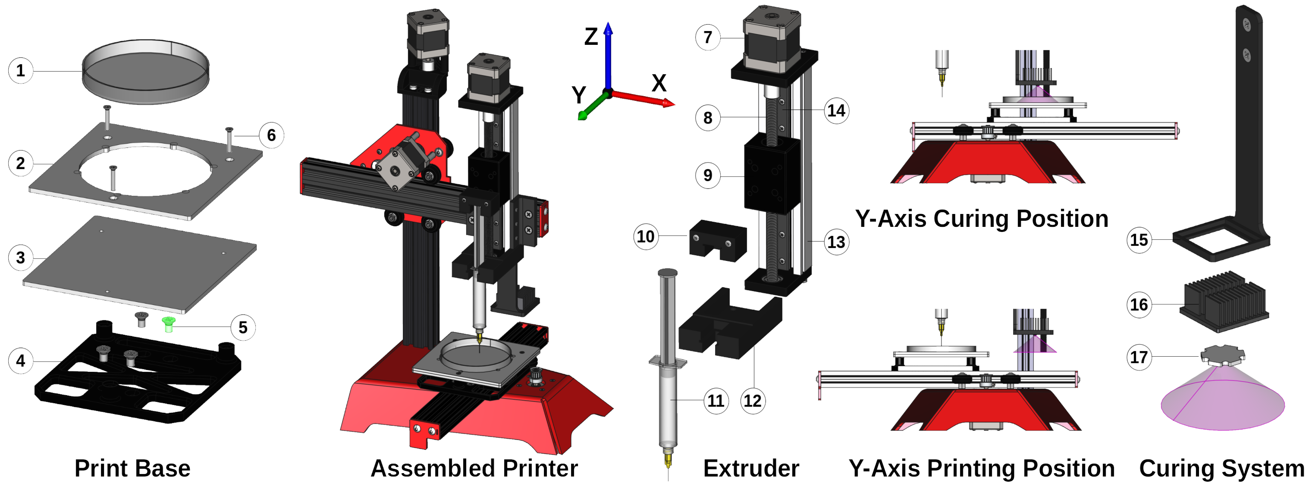
Figure 3.
Diagram showing the electrical interconnections between the major elements of the fabrication system. Yellow box: microcontroller and placement. Orange box: motor drivers and placement. Red and black lines: power. Multicolour (orange, green blue, red): motor connectors.
Figure 3.
Diagram showing the electrical interconnections between the major elements of the fabrication system. Yellow box: microcontroller and placement. Orange box: motor drivers and placement. Red and black lines: power. Multicolour (orange, green blue, red): motor connectors.

Figure 4.
Flow diagram in the form of a closed-loop system outlining the major stages required to manufacture a PDMS structure. This is controlled via a loop counter variable ‘i’ to print N layers. Italicised variables outside blocks indicate the control system processed sequentially.
Figure 4.
Flow diagram in the form of a closed-loop system outlining the major stages required to manufacture a PDMS structure. This is controlled via a loop counter variable ‘i’ to print N layers. Italicised variables outside blocks indicate the control system processed sequentially.

Figure 5.
Captured and labelled photos of the assembled printer. (1) x-axis, (2) z-axis, (3) y-axis, (4) print base support, (5) extruder, (6) syringe loaded with PDMS polymer ink, (7) scaffold being printed, (8) syringe tip, (9) LED support arm, (10) irradiated structure, (11) heat sink, (12) motor, (13) strong frame, (14) adapter, (15) container, (16) syringe tip, (17) PDMS material in syringe, (18) carriage, (19) lead screw, (20) coupler.

Figure 6.
Calibration of the extrusion mechanism. The blue squares represent the first calibration using a ratio of 1000, with the blue line as its linear regression model (R = 0.999, n = 11, m = 1.62). The red circles represent the second calibration using a ratio of 617.29, with the red line as its linear regression model (R = 0.999, n = 11, m = 1.0). Data points represent the average across 3 measurements. Error bars represent the standard deviation.

Figure 7.
Images of the 3D structures fabricated with 20, 50, and 70% infill.

Figure 8.
(Left) Mechanical testing of printed structures with 50% and 70% infill after cyclic compression test (×100). (Right) Microscope images of the printed structures with 70% (top) and 50% (bottom) infill density.
Figure 8.
(Left) Mechanical testing of printed structures with 50% and 70% infill after cyclic compression test (×100). (Right) Microscope images of the printed structures with 70% (top) and 50% (bottom) infill density.


Table 1.
PDMS structure fabrication parameters.
| Parameter | Value | Unit |
|---|---|---|
| Print speed (XYZ movement) | 5 | mm.s |
| Syringe size | 10 | cc |
| XYZ motor driver control | 600 | mV |
| Micro-step resolution | 16 | Steps |
| Layer height | 0.6 | mm |
| Extrusion feed rate | 40 | .s |
| Retraction distance | 4 | mm |
| Retraction speed | 3 | mm.s |
| Layer to LED distance | 50 | mm |
| LED irradiance | 25 | W.cm |
| Tip diameter/layer height | 580 | |
| Room temperature | 20 | °C |
Table 2.
List of components for developing the printer in this study. Numbers for the customised parts refer to the labelled elements in Figure 2. The component fields for the custom parts are named according to their filename.
Table 2.
List of components for developing the printer in this study. Numbers for the customised parts refer to the labelled elements in Figure 2. The component fields for the custom parts are named according to their filename.
| ID | Component | Supplier | Number/Identifier |
|---|---|---|---|
| 1 | Printer frame | ME 3D | ME2 |
| 2 | Extruder motor | RobotDigg | 42HS48-2504 |
| 3 | Extruder frame | RobotDigg | 100-WL-81 |
| 4 | Curing LED | Mouser (AU) | LZ1-10UV00-0000 |
| 5 | Curing heat sink | Mouser (AU) | 6238PB-MT5 |
| 6 | DC–DC regulator | Jaycar | XC4514 |
| 7 | SyringeBungHolder.step | Customised | 10 |
| 8 | CarriageMount.step | Customised | 12 |
| 9 | MountingBracket.step | Customised | 13 (mnt) |
| 10 | LEDArm.step | Customised | 15 |
Disclaimer/Publisher’s Note: The statements, opinions and data contained in all publications are solely those of the individual author(s) and contributor(s) and not of MDPI and/or the editor(s). MDPI and/or the editor(s) disclaim responsibility for any injury to people or property resulting from any ideas, methods, instructions or products referred to in the content. |
© 2023 by the authors. Licensee MDPI, Basel, Switzerland. This article is an open access article distributed under the terms and conditions of the Creative Commons Attribution (CC BY) license (https://creativecommons.org/licenses/by/4.0/).
Share and Cite
MDPI and ACS Style
Fay, C.D.; Wu, L. Cost-Effective 3D Printing of Silicone Structures Using an Advanced Intra-Layer Curing Approach. Technologies 2023, 11, 179. https://doi.org/10.3390/technologies11060179
AMA Style
Fay CD, Wu L. Cost-Effective 3D Printing of Silicone Structures Using an Advanced Intra-Layer Curing Approach. Technologies. 2023; 11(6):179. https://doi.org/10.3390/technologies11060179
Chicago/Turabian StyleFay, Cormac D., and Liang Wu. 2023. "Cost-Effective 3D Printing of Silicone Structures Using an Advanced Intra-Layer Curing Approach" Technologies 11, no. 6: 179. https://doi.org/10.3390/technologies11060179
Note that from the first issue of 2016, this journal uses article numbers instead of page numbers. See further details here.