Abstract
The layer-by-layer building methodology used within the powder bed process of Selective Laser Melting facilitates control over the degree of melting achieved at every layer. This control can be used to manipulate levels of porosity within each layer, effecting resultant mechanical properties. If specifically controlled, it has the potential to enable customisation of mechanical properties or design of in-built locations of mechanical fracture through strategic void placement across a component, enabling accurate location specific predictions of mechanical failure for fail-safe applications. This investigation examined the process parameter effects on porosity formation and mechanical properties of 316L samples whilst maintaining a constant laser energy density without manipulation of sample geometry. In order to understand the effects of customisation on mechanical properties, samples were manufactured with in-built porosity of up to 3% spanning across ~1.7% of a samples’ cross-section using a specially developed set of “hybrid” processing parameters. Through strategic placement of porous sections within samples, exact fracture location could be predicted. When mechanically loaded, these customised samples exhibited only ~2% reduction in yield strength compared to samples processed using single set parameters. As expected, microscopic analysis revealed that mechanical performance was closely tied to porosity variations in samples, with little or no variation in microstructure observed through parameter variation. The results indicate that there is potential to use SLM for customising mechanical performance over the cross-section of a component.
1. Introduction and Background
Research in the field of Selective Laser Melting (SLM) is broad, with many focused on parameter optimisation for achieving consistent high density parts and establishing a relationship between parameters and final part mechanical properties for specific materials [1,2,3,4,5,6,7,8,9,10,11,12,13]. Understanding the phenomenon of residual stresses building up in SLM parts due to high thermal gradients and strategies for minimising the residual stresses and their detrimental effects such as cracking and warping of parts are other areas of interest for researchers [14,15,16,17,18,19,20,21]. Analysis of post-processing operations such as hipping and heat treatment of additively manufactured parts has also been a point of interest for researchers as these can enable significant improvement in part density and mechanical properties [15,18,22,23]. Despite the increased interest and growth in SLM research, the complexity of this rapid solidification process has resulted in high value industries approaching this technology with caution [24]. In addition, the requirements for process repeatability, tolerances, and feedstock traceability have increased in recent years [25] and are understandably strict in sectors such as aerospace and biomedical orthopedics.
SLM of stainless steel alloys, particularly 316L, has been of major interest to researchers due to its high corrosion resistance, formability, strength, weldability, and biocompatibility. SS 316L is suitable for medical applications (implants and prosthesis), pharmaceuticals, architectural applications, fasteners, aerospace parts, marine and chemical applications, and heat exchangers [26,27]. SS 316L SLM parts in as-built conditions have exhibited fatigue properties similar to conventionally manufactured parts, mainly due to the high ductility even after SLM processing [7]. If the correct combination of process parameters are chosen, SLM steel samples usually exhibit improved tensile properties compared to conventionally manufactured steel samples [28].
Customised Mechanical Properties Using SLM
The layer by layer building methodology used within SLM offers the potential for mechanical properties to be controlled layer to layer. However, to date, limited research has been undertaken exploring this possibility. Theoretically this variation in mechanical properties can be generated through a number of methods. The first and most obvious is by geometry manipulation, designing with the assistance of computational software can allow designers to create structures that will have a specific mechanical response to external loading. This feature is not exclusive to additive manufacturing technologies and can be achieved through a variety of other manufacturing processes (however, complexity may be limited when using conventional processes). Secondly properties can be controlled through the introduction of variable materials (i.e., functionally graded materials), although this is challenging due to the potential for thermal expansion mismatch between materials leading to delamination of multi-material layers, it is also difficult to recycle and separate materials from a powder bed that consists of graded multi-materials. Thirdly, microstructure manipulation could be used to vary mechanical properties across the cross-section of parts, this may be achieved through adjustment of melting regimes employed at each layer [3,29]. However, due to the rapid solidification of material within SLM, it is often difficult to alter the microstructure of individual layers significantly from their standard fine dendritic form solely through parameter control (i.e., laser power, exposure time, etc.). Suitable SLM processing conditions (i.e., promoting high density components) and rapid solidification limit generation of sufficient variability within the thermal history of each layer to promote enough microstructural change to allow mechanical performance to vary significantly. Microstructures can be altered through multiple reheating strategies and powder bed pre-heating, but this tends to affect multiple layers across a component and precise layer to layer control will be challenging. Pre-heating the powder bed to higher temperatures can assist in delaying solidification and coarsen the microstructure, however this heating will affect the majority of layers across a component without permitting control over microstructural variation across specific layers. Finally, mechanical properties could be altered through the introduction of controllable features such as porosity across a component. This can be controlled through varying laser processing parameters layer to layer and inducing lack of fusion porosity. The mechanical properties can be artificially altered, making the areas across a component mechanically weaker in the tensile compared to a fully dense region, this can be designed across a part, promoting preferential deformation of parts or failure at strategic locations. Currently, when tensile testing SLM components the exact location of failure is random and highly unpredictable without the use of X-ray analysis. Customising the mechanical performance of an SLM sample may be particularly useful for applications requiring a fail-safe mechanism to minimise harm or respond appropriately to specific types of loading conditions, examples include pressure relief in pressure valves or blow-off panels used in enclosure. Designed premature failure may also be used to prevent more expensive or catastrophic failure from occurring further down the line.
2. Experimental Methodology
As an overview of the experimental methodology, processing parameters were adjusted so that variation in sample density could be attained. Having established what effect these adjusted parameters had, samples were created such that variation in mechanical properties (i.e., preferential point of failure) would be created across strategic locations within samples. Parts were tested for density, hardness, and tensile strength.
A Renishaw SLM 125 was used during investigations, this system uses a 200 W fibre laser to process metallic powdered feedstock within a purged argon atmosphere. Gas atomised SS AISI 316L (15–45 micron) was used as the feedstock material, its composition is shown in Table 1.

Table 1.
Weight % Composition.
2.1. Sample Testing
10 × 10 mm cubes were fabricated for testing hardness using a Vickers hardness testing machine (BSEN ISO 6507-1:2005 [30]). The level of porosity in the specimen was estimated by area fraction analysis of representative micrographs/fields using a method based on ASTM E2109-01 (2007) and BS 7590:1992 [31,32]. Tensile test specimens were manufactured according to the ASTM E8 standard [33]. The specimens were tested on a Tinius Olsen H25K-S UTM Benchtop Materials Tester. A summary of key dimensions of the tensile test pieces are shown in Figure 1. The samples were built vertically and tested along this axis.
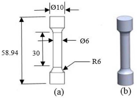
Figure 1.
Specimen dimensions (a); and CAD file (b).
2.2. Processing Parameter Selection
For processing SS 316L a set of recommended laser process parameters were specified by SLM OEM Renishaw for creating components at full density, shown in Table 2.
Table 2.
Manufacturer (Renishaw) recommended processing parameter values for SS 316L.
Various processing parameters affect the SLM process, these may be direct or indirect as specified by Yadroitsev et al. [2]. However, the principal parameters in SLM—those which have the most substantial effect—have been identified as being laser power, spot size diameter, exposure time, spot spacing (scan speed), hatch distance, and powder layer thickness [1]. Varying laser power and scan speed individually affects the laser energy density that is used to melt the powder bed during SLM, and controls levels of porosity within a component. This implies that there is an “optimum” energy density for fabricating fully dense parts free of irregularities as noted by Kurian et al. [10]. The laser energy density behaviour is described by Equation (1), and it was shown that laser power and exposure time are inversely proportional (other variables kept constant), in theory it is possible to vary both the laser power and exposure time in unison while maintaining the energy density delivered constant.
P: Laser power (W, J/s); t: Exposure time (s); x: Point distance (mm); l: Layer Thickness (mm); h: Hatch Spacing (mm); Q: Energy density (J/).
For these reasons, a variation of laser power with exposure time was performed, while maintaining an arbitrary “optimal” energy density. The energy density selected was 62 J/, consistent with the Renishaw SLM 125 advised processing parameters. This energy density was maintained in combination with varying exposure times and laser powers as shown in Table 3, continuous melt tracks were identified at powers as low as 150 W in other work [9]. Other SLM parameters were kept constant.
Table 3.
Varied parameter range and processing set name/condition.
Using the Renishaw SLM 125 and processing SS 316L powder, three repeat samples of each specimen type A, B, and C were produced as shown in Figure 2.
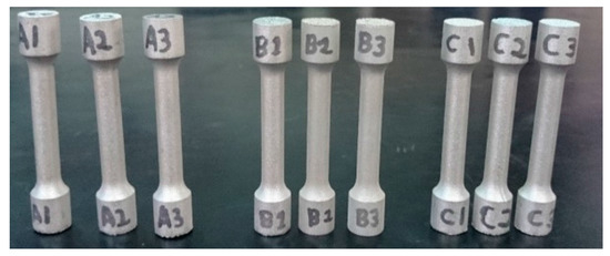
Figure 2.
Uniform specimen sets.
The specimens were attached to the substrate plate via support structures in order to facilitate removal. Images of the support structures, including the surface texture of the specimen, with top and bottom (chiseled) sides are shown in Figure 3.
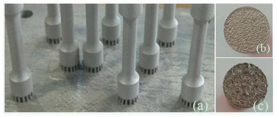
Figure 3.
Support structures (a); and top (b); bottom (c) surface texture.
3. Results
Three sets of SS 316L cubed samples and tensile test bars were produced for each processing condition (A, B, C) using SLM parameters shown in Table 3. Based on these results, further customised samples were created and tested, their results are later detailed in Section 3.3.
3.1. Optical Microscopy
Microscopy was performed as described in Section 2.1, initially testing cubed samples for porosity and shown in Figure 4. Samples produced with parameter set A had an average density of 99.8%, parameter set B 99.1%, and parameter set C 96.8%. Even though energy density was maintained at 62 J/, as the laser power was reduced the porosity within samples increased due to a potential increase in lack of fusion, evident from the irregularly shaped pores. Subsequently, the etched samples were examined for a more detailed view of the microstructure shown in Figure 5, microstructures were typical of those produced using SLM with little or no variation in microstructure between samples when melting at different laser powers.
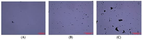
Figure 4.
Porosity of cubes fabricated using parameters (A) (200 W); (B) (175 W); (C) (150 W).
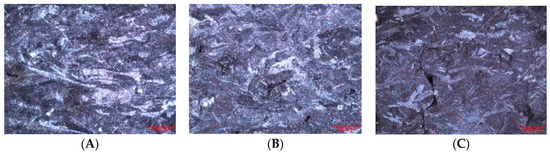
Figure 5.
Microstructure of cubes fabricated using parameters (A) (200 W); (B) (175 W); (C) (150 W).
3.2. Tensile Testing
Tensile testing was performed on each specimen set (A, B, and C). The specimens fractured at varying points along the gauge length as can be seen in Figure 6. It can be seen that fracture location across the gauge length of samples are random and unpredictable.
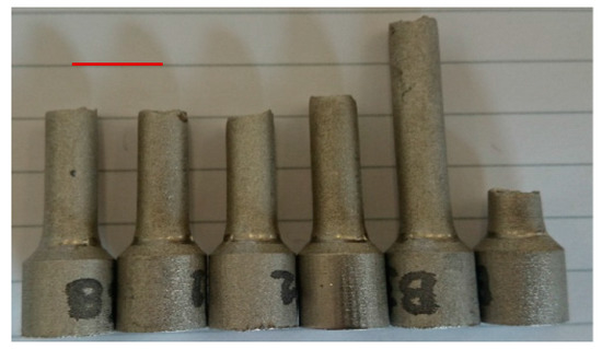
Figure 6.
Set B (175 W) specimen fracture locations.
Figure 7 shows stress-strain plots from tensile testing for one representative sample from each processing condition. It reveals that a 3% porosity variation between samples A–C processed at constant energy densities (but varying laser powers) was sufficient to generate variation in mechanical properties. As expected, trends generally indicate weaker parts (reduced yield strength, UTS, and fracture strength) were formed with use of lower power lasers due to higher levels of part porosity. The mean average for all samples (×3 repeats) is shown in Table 4 and Figure 8.
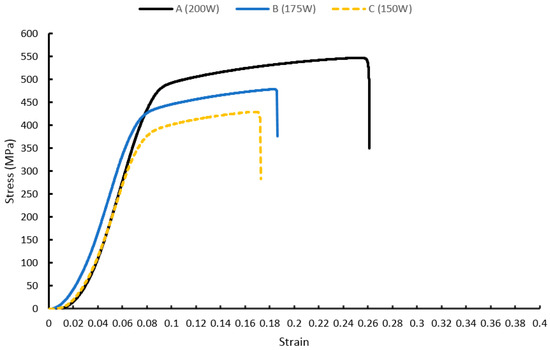
Figure 7.
Uniform specimen stress-strain plot.
Table 4.
Mean mechanical property values for uniform specimen sets.
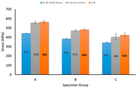
Figure 8.
Comparison of mean mechanical properties between samples (A) (200 W); (B) (175 W); (C) (150 W).
3.3. Hardness Testing Results
Hardness tests were performed on cubic SLM samples. The mean average result for each sample is shown in Table 5. The higher apparent scan speeds (generated with shorter exposure times) used in sample A led to increased sample hardness due to faster solidification of the melt pool. Slower apparent scan speeds (as those used in sample C) lead to slower solidification rates and therefore a softer material. Higher hardness values generally indicate higher tensile strength and are therefore in agreement with the tensile results for each sample detailed in Section 3.1.
Table 5.
Uniform specimen hardness testing results.
3.4. Customised Specimens
The results obtained for the uniform sample set show that there is significant variance in the mechanical properties as energy density remains constant and laser powers and exposure times are adjusted. The uniform sample set fractured in unpredictable locations within the gauge length (Figure 6). In order to customise mechanical properties and create predictable failure/break locations across specimens, two different sets of processing parameters were used to build a single tensile test specimen to initiate “structural change” within the sample. “Failure points” were introduced in the customised specimens at different locations along the gauge length of each sample as shown in Figure 9.
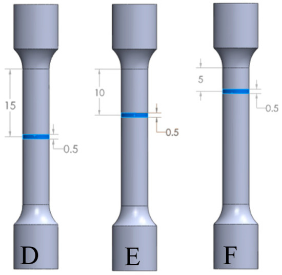
Figure 9.
Designed failure locations for customised specimen set.
In order for the customised specimens to be produced on the SLM machine, each specimen was split into three parts; the bottom end, the top end, and the failure point. This distinction was made in order for the failure point to be assigned a different processing parameter set compared to the top/bottom ends. For the customised specimen sets D, E, and F (Figure 9), the failure points were placed at 15, 10, and 5 mm respectively from the top section of the gauge length. The failure point was designed to be 10 layers thick (i.e., 500 µm) to encourage an adequate or distinct change in mechanical performance. The processing parameters were 200 W laser power with 70 µs exposure time for the top/bottom ends of the sample (original parameter set A), and 150 W with 93 µs for the failure point (original parameter set C). These parameters were selected from the uniform sample sets A and C as they displayed the largest variation in mechanical properties as detailed in Section 3.2. The specimens produced are geometrically identical to the uniform tensile samples produced in Section 3.2, however, the failure point locations were labelled on the customised specimens for better visualisation, as shown in Figure 10.
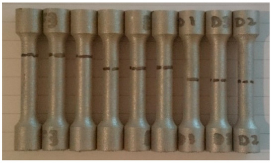
Figure 10.
Customised specimen set failure points.
Tensile tests were performed on the customised specimen sets D, E, and F. All samples fractured at the marked locations for designed in-built failure point, shown in Figure 11. This is evidence that predictable and controlled fracture/failure can be achieved through selection and implementation of multiple “hybrid” laser processing parameters within a single build.
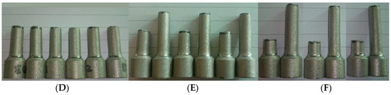
Figure 11.
Customised specimen controlled fracture locations (D–F).
The mechanical properties of the sample sets D, E, and F are shown in Table 6 with the stress-strain plot for these samples shown in Figure 12. As expected, the mechanical properties of these customised parts were weaker than samples produced entirely with optimum parameter A (200 W) settings (Table 4), this is because approximately 1.7% of the SLM gauge length was produced using parameter set C (150 W) marginally increasing porosity within the component across 10 layers (500 µm). When comparing single parameters of set A samples, customised samples set D held approximately 4% lower yield strength and 10% lower UTS. Customised sample sets E and F showed a yield strength comparable to that of sample set A, while the UTS showed a reduction of approximately 5.5%.
Table 6.
Mean mechanical property values for customised specimen sets.
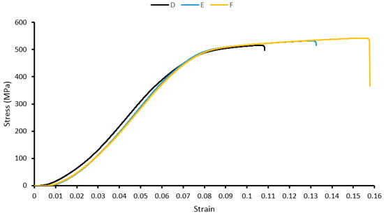
Figure 12.
Customised specimen stress-strain plot.
4. Discussion
The results obtained for the porosity of the samples in Figure 4 clearly indicate an increase in porosity and pore size when progressing from parameter set A to C. The increased porosity may have arisen due to lack of fusion or Rayleigh instability, balling, or poor wetting characteristics as detailed by Rombouts, M. et al. [12]. With regards to the microstructure, long elongated grains were observed parallel to the building direction and consistent with other SLM work processing 316L [7]. These grains exhibit austenitic behaviour as is common in most 300 series stainless steels (316L included) [11,34]. The production of austenite grains is highly temperature and cooling rate dependent, with minimal variation observed in microstructures produced using samples sets A, B, and C, these observations are consistent with other work on SLM processing 316L with variable processing parameters [7].
From the stress-strain curve of the uniform sample set in Figure 7, it is clear that even though the energy density transferred to the sample was kept constant for samples A, B, and C, the change in parameters had an effect on the density of samples and subsequent mechanical properties. UTS and fracture strength have relatively close values, indicating signs of brittle behaviour, additionally supported/explained by the reduced necking at the specimen fracture point, results consistent with work conducted by Riemer, A., et al. [7]. A notable effect was observed in the 0.2% yield stress, UTS, and fracture stress, with a 29% decrease in yield, 33% decrease in UTS, and 38% decrease in fracture when progressing from parameter set A to C. There is a high variance in the measured maximum strain results with an average standard deviation of 19%. However, there is still a clear trend of decreasing max strain with decreasing laser power and increased exposure time, with a 49% decrease in average maximum strain from parameter set A to C. This decrease in average maximum strain can be attributed to the increase in porosity. According to ref. [35], decrease in porosity resulted in a significant improvement in elongation. Additionally, set A—having the larger maximum strain—exhibits more of a ductile behaviour by absorbing more energy per unit volume (area under stress-strain curve), and conversely by having a significantly lower maximum strain, set C exhibits a more brittle behaviour with less energy per unit of volume absorbed. In addition to these observations from the tensile test, the hardness testing results from Table 5 shows a trend of decreasing hardness with decreased laser power and increased exposure time, with a 21% decrease progressing from set A to C. Even with use of a constant energy density delivered to the SS 316L powder, variation in the process parameters leads to changes in the material behaviour.
For the customised specimens, samples fractured at the designed failure location which were created through processing specific layers with “weaker” processing parameters as in set C, while maintaining set A properties throughout the remainder of the sample. This introduces a predictable failure point within samples, and prevents randomness of fracture across the gauge length of samples (as those seen in uniform parameter set samples, Figure 6). The added capability of designing fracture locations within samples results using “hybrid” processing parameters (sets D, E, F) caused samples to have approximately a 2% lower yield strength and 7% lower UTS than standard uniforms samples (processed set A).
5. Conclusions
Whilst maintaining a consistent energy density, sample porosity varied as laser power and exposure time was modified. This change is linked to lack of fusion porosity or Rayleigh instabilities within the melt pool. It was observed that tensile samples produced with a uniform parameter set would fracture at random locations across its gauge length. Using a set of “hybrid” processing parameters, sample mechanical properties could be tailored such that specific fracture points within a sample could be designed into a component. Using two SLM processing parameters sets (hybrid parameters) to melt specific locations within a test piece, an additional 3% porosity across a segment making up approximately 1.7% of the sample’s gauge length was generated. This was sufficient to initiate consistent and repeatable fracture across this segment while only reducing the yield strength of the entire sample by approximately 2% compared to uniform single set parameter specimens (these produced un-customised, random fracture locations).
This controlled in-built failure of components requires particular features to be “written” into the structure of a component through modification of SLM processing parameters at specific layers across a component. Controlled in-built failure of components and customisation of components’ mechanical performance is a feature that is difficult to achieve with conventional metal forming techniques. Such customised components can form part of a larger assembly, which are intentionally engineered to exhibit particular behaviours when under specific external loading conditions in order to protect other components within the system. Examples of parts include rupture discs used for pressure relief in pressure vessels; blow-off panels used in enclosures, vehicles, or buildings where overpressure may occur; and shear pins preventing mechanical overloads. Using the approach of “hybrid” processing, parameters, and porosity within samples may be graded/adjusted layer to layer. This customisation of mechanical properties will exert more refined control over specific part fracture points or general mechanical behaviour in order to further enhance the overall performance or capabilities of a component. As research momentum in this underdeveloped area progresses, additive manufacturing will be able to lay claim and present an additional benefit of this technology. Further exploitation of the unique layer-by-layer building principle of SLM can lead to customisation of components’ mechanical performance.
Author Contributions
Andrei Ilie planned experimentation and undertook majority of testing, Haider Ali assisted with testing, analysis and manuscript preparation and Kamran Mumtaz supervised overall project.
Conflicts of Interest
The authors declare no conflict of interest.
References
- Childs, T.H.C.; Hauser, C.; Badrossamay, M. Mapping and Modelling Single Scan Track Formation in Direct Metal Selective Laser Melting. CIRP Ann. Manuf. Technol. 2004, 53, 191–194. [Google Scholar] [CrossRef]
- Yadroitsev, I.; Bertrand, P.; Smurov, I. Parametric analysis of the selective laser melting process. Appl. Surf. Sci. 2007, 253, 8064–8069. [Google Scholar] [CrossRef]
- Niendorf, T.; Leuders, S.; Riemer, A.; Richard, H.A.; Tröster, T.; Schwarze, D. Highly Anisotropic Steel Processed by Selective Laser Melting. Metall. Mater. Trans. B 2013, 44, 794–796. [Google Scholar] [CrossRef]
- Yadroitsev, I.; Thivillon, L.; Bertrand, P.; Smurov, I. Strategy of manufacturing components with designed internal structure by selective laser melting of metallic powder. Appl. Surf. Sci. 2007, 254, 980–983. [Google Scholar] [CrossRef]
- Fischer, P.; Romano, V.; Weber, H.P.; Karapatis, N.P.; Boillat, E.; Glardon, R. Sintering of commercially pure titanium powder with a Nd:YAG laser source. Acta Mater. 2003, 51, 1651–1662. [Google Scholar] [CrossRef]
- Kruth, J.P.; Levy, G.; Klocke, F.; Childs, T.H. Consolidation phenomena in laser and powder-bed based layered manufacturing. CIRP Ann. Manuf. Technol. 2007, 56, 730–759. [Google Scholar] [CrossRef]
- Riemer, A.; Leuders, S.; Thöne, M.; Richard, H.A.; Tröster, T.; Niendorf, T. On the fatigue crack growth behavior in 316L stainless steel manufactured by selective laser melting. Eng. Fract. Mech. 2014, 120, 15–25. [Google Scholar] [CrossRef]
- Yasa, E.; Kruth, J.P. Microstructural investigation of Selective Laser Melting 316L stainless steel parts exposed to laser re-melting. Procedia Eng. 2011, 19, 389–395. [Google Scholar] [CrossRef]
- Mertens, A.; Reginster, S.; Contrepois, Q.; Dormal, T.; Lemaire, O.; Lecomte-Beckers, J. Microstructures and mechanical properties of stainless steel AISI 316L processed by selective laser melting. Mater. Sci. Forum 2014, 783, 898–903. [Google Scholar] [CrossRef]
- Antony, K.; Arivazhagan, N.; Senthilkumaran, K. Numerical and experimental investigations on laser melting of stainless steel 316L metal powders. J. Manuf. Processes 2014, 16, 345–355. [Google Scholar] [CrossRef]
- Zhang, B.; Dembinski, L.; Coddet, C. The study of the laser parameters and environment variables effect on mechanical properties of high compact parts elaborated by selective laser melting 316L powder. Mater. Sci. Eng. A 2013, 584, 21–31. [Google Scholar] [CrossRef]
- Rombouts, M.; Kruth, J.P.; Froyen, L.; Mercelis, P. Fundamentals of Selective Laser Melting of alloyed steel powders. CIRP Ann. Manuf. Technol. 2006, 55, 187–192. [Google Scholar] [CrossRef]
- Simchi, A. Direct laser sintering of metal powders: Mechanism, kinetics and microstructural features. Mater. Sci. Eng. A 2006, 428, 148–158. [Google Scholar] [CrossRef]
- Roberts, I.A. Investigation of Residual Stresses in the Laser Melting of Metal Powders in Additive Layer Manufacturing; University of Wolverhampton: Wolverhampton, UK, 2012; p. 246. [Google Scholar]
- Knowles, C.R.; Becker, T.H.; Tait, R.B. The effect of heat treatment on the residual stress levels within direct metal laser sintered Ti-6Al-4V as measured using the hole-drilling strain gauge method. In Proceedings of the 13th international Rapid Product Development Association of South Africa (RAPDASA) Conference, Sun City, South Africa, 31 October–2 November 2012; pp. 1–10.
- Chatterjee, A.N.; Kumar, S.; Saha, P.; Mishra, P.K.; Choudhury, A.R. An experiment design approach to selective laser sintering of low carbon steel. J. Mater. Process. Technol. 2003, 136, 151–157. [Google Scholar] [CrossRef]
- Matsumoto, M.; Shiomi, M.; Osakada, K.; Abe, F. Finite element analysis of single layer forming on metallic powder bed in rapid prototyping by selective laser processing. Int. J. Mach. Tools Manuf. 2002, 42, 61–67. [Google Scholar] [CrossRef]
- Kruth, J.P.; Deckers, J.; Yasa, E.; Wauthlé, R. Assessing and comparing influencing factors of residual stresses in selective laser melting using a novel analysis method. Proc. Inst. Mech. Eng. Part B J. Eng. Manuf. 2012, 226, 980–991. [Google Scholar] [CrossRef]
- Joe Elambasseril, S.F.; Matthias, B.; Milan, B. Influence of Process Parameters on Selective Laser Melting of Ti 6Al-4V Components; RMIT University: Ho Chi Minh City, Vietnam, 2012. [Google Scholar]
- Papadakis, L.; Loizou, A.; Risse, J.; Bremen, S. A thermo-mechanical modeling reduction approach for calculating shape distortion in SLM manufacturing for aero engine components. In Proceedings of the 6th International Conference on Advanced Research in Virtual and Rapid Prototyping, Leiria, Portugal, 1–5 October 2013.
- Casavola, C.; Campanelli, S.L.; Pappalettere, C. Experimental analysis of residual stresses in the selective laser melting process. In Proceedings of the XIth International Congress and Exposition, Orlando, FL, USA, 2–5 June 2008.
- Thöne, M.; Leuders, S.; Riemer, A.; Tröster, T.; Richard, H.A. Influence of heat-treatment on selective laser melting products–eg Ti6Al4V. In Proceedings of the Solid Freeform Fabrication Symposium SFF, Austin, TX, USA, 6–8 August 2012.
- Shiomi, M.; Osakada, K.; Nakamura, K.; Yamashita, T.; Abe, F. Residual Stress within Metallic Model Made by Selective Laser Melting Process. CIRP Ann. Manuf. Technol. 2004, 53, 195–198. [Google Scholar] [CrossRef]
- ASTM International. Additive Manufacturing Technology Standards; ASTM International: West Conshohocken, PA, USA, 2014. [Google Scholar]
- Wohlers Associates, Inc. Wohlers Report 2008: State of the Industry; Annual Worldwide Progress Report; Wohlers Associates, Inc.: Fort Collins, CO, USA, 1996. [Google Scholar]
- Gu, D.; Shen, Y. Balling phenomena in direct laser sintering of stainless steel powder: Metallurgical mechanisms and control methods. Mater. Des. 2009, 30, 2903–2910. [Google Scholar] [CrossRef]
- Yadroitsev, I.; Gusarov, A.; Yadroitsava, I.; Smurov, I. Single track formation in selective laser melting of metal powders. J. Mater. Process. Technol. 2010, 210, 1624–1631. [Google Scholar] [CrossRef]
- Hanzl, P.; Zetek, M.; Bakša, T.; Kroupa, T. The Influence of Processing Parameters on the Mechanical Properties of SLM Parts. Procedia Eng. 2015, 100, 1405–1413. [Google Scholar] [CrossRef]
- Vrancken, B.; Thijs, L.; Kruth, J.P.; Van Humbeeck, J. Heat treatment of Ti6Al4V produced by Selective Laser Melting: Microstructure and mechanical properties. J. Alloys Compd. 2012, 541, 177–185. [Google Scholar] [CrossRef]
- ISO 6507-1:2005, Metallic Materials—Vickers Hardness Test—Test Method. Available online: http://www.iso.org/iso/catalogue_detail.htm?csnumber=37746 (accessed on 20 February 2017).
- ASTM International. Standard Test Methods for Determining Area Percentage Porosity in Thermal Sprayed Coatings; E2109-01(2007); ASTM International: West Conshohocken, PA, USA, 2007. [Google Scholar]
- British Standards Institution (BSI). Method for Statistically Estimating the Volume Fraction of Phases and Constituents by Systematic Manual Point Counting with a Grid; BS 7590:1992; BSI: London, UK, 1992. [Google Scholar]
- ASTM International. Standard Test Methods for Tension Testing of Metallic Materials; E8/E8M-13a; ASTM International: West Conshohocken, PA, USA, 2013. [Google Scholar]
- Reed-Hill, R.E.; Abbaschian, R. Physical Metallurgy Principles; PWS-Kent Publisher: Boston, MA, USA, 1992. [Google Scholar]
- Qiu, C.; Adkins, N.J.E.; Attallah, M.M. Selective laser melting of Invar 36: Microstructure and properties. Acta Mater. 2016, 103, 382–395. [Google Scholar] [CrossRef]
© 2017 by the authors. Licensee MDPI, Basel, Switzerland. This article is an open access article distributed under the terms and conditions of the Creative Commons Attribution (CC BY) license ( http://creativecommons.org/licenses/by/4.0/).