
Vision-Based Robot Following Using PID Control

1
Computer Science Engineering, Rajiv Gandhi Universities of Knowledge and Technologies, Nuzvid, PIN-521202, India
2
Robotics and Artificial Intelligence Laboratory, Indian Institute of Information Technology, Allahabad, PIN-211012, India
*
Author to whom correspondence should be addressed.
Technologies 2017, 5(2), 34; https://doi.org/10.3390/technologies5020034
Submission received: 15 February 2017
/
Revised: 21 May 2017
/
Accepted: 7 June 2017
/
Published: 10 June 2017
Abstract
:Applications like robots which are employed for shopping, porter services, assistive robotics, etc., require a robot to continuously follow a human or another robot. This paper presents a mobile robot following another tele-operated mobile robot based on a PID (Proportional–Integral-Differential) controller. Here, we use two differential wheel drive robots; one is a master robot and the other is a follower robot. The master robot is manually controlled and the follower robot is programmed to follow the master robot. For the master robot, a Bluetooth module receives the user’s command from an android application which is processed by the master robot’s controller, which is used to move the robot. The follower robot receives the image from the Kinect sensor mounted on it and recognizes the master robot. The follower robot identifies the x, y positions by employing the camera and the depth by using the Kinect depth sensor. By identifying the x, y, and z locations of the master robot, the follower robot finds the angle and distance between the master and follower robot, which is given as the error term of a PID controller. Using this, the follower robot follows the master robot. A PID controller is based on feedback and tries to minimize the error. Experiments are conducted for two indigenously developed robots; one depicting a humanoid and the other a small mobile robot. It was observed that the follower robot was easily able to follow the master robot using well-tuned PID parameters.
1. Introduction
Robots are increasingly being used in home and office environments for a variety of tasks. One of the application areas of these robots is as ‘personal assistants’. The robots may be used by the human master to take commands as the human moves, to carry items of interest for the human, and to complete manipulation tasks that the human specifies, etc. Common applications include robots as porters to carry luggage, robots to transport goods from one place to other, and robots to help the human in a supermarket or a shopping mall, etc. All of these applications require a robot to follow a human. Sometimes, the robot may be required to follow another robot instead.
The master robot is an android Bluetooth-based robot which is designed by us with Arduino and the HC-05 Bluetooth module. Social Mobile Autonomous Research Test bed (SMART) is a mobile robot that was designed in IIIT Allahabad for social interaction. The robot has a differential wheel base for mobility, two controllable arms for human interaction, a vision system, and a speaker set. The current capability of the robot includes a tour of the laboratory when starting from a fixed location, without tracking humans. This project is a step towards making SMART a robot assistant that is capable of following people. As the first step, this paper proposes a mechanism wherein SMART is made to follow another robot. The paper demonstrates the capability of SMART to follow a master robot, which can be extended to following humans by developing a human recognition system [1,2]. Another motivation is from swarm robotics, where slave robots do the work and follow the master robots. The main motivation of this project is to use this knowledge in SMART.
The slave robot uses 3-D vision to detect the master robot, using a Kinect sensor that obtains a depth image along with a monocular camera image known as the RGB-D image. The Kinect measures the depth by a triangulation process [3]. The RGB-D images are well suited to solve the ego-motion (3D motion of a camera within an environment) estimation problem of an agent [4]. Modern day robots are primarily vision driven. Computer Vision essentially deals with image processing techniques for noise removal, the detection of the area of interest, and recognition of the object of interest [5]. Further vision techniques can be used to know the position of an object or to localize the object of interest. In our case, the follower robot senses the master robot with the help of Kinect sensors. In this project, the computer vision plays a major role in detecting, recognizing, and localizing the master robot through the 3D camera of the slave robot.
Every sensor of the robot reports the readings in its own frame of reference. Similarly, every actuator of the robot obtains inputs in its own frame of reference. Transformations enable conversions between the frames of reference. In this paper, the follower robot finds the master robot, but the located position needs to be transformed from the image coordinate frame to Kinect’s coordinate frame, and ultimately, the follower robot’s frame of reference. This is done based on transformation techniques with the help of the Kinect calibration matrix.
The problem of robot control relates to the ability to guide the robot such that the traced trajectory of the robot is as close as possible to the desired trajectory. Closed loop control systems are widely used, which obtain feedback in the form of an error signal and send corrective signals to the robot such that the error is reduced.
In this paper, we use an RGB image of the master robot taken from the Kinect mounted on the slave robot for detection and depth values for finding the distance between the master and slave robots. Both the master and follower are mobile robots, so every time, the distance between the master and follower varies. The follower has to maintain the minimum distance and the orientation towards the master is conducted by the RGBD image processing. The follower robot follows the master based on the detections in the RGB image and the depth.
A lot of research has been carried out in the field of robot following, especially in the field of differential wheel robots. A low computational cost method for terrestrial mobile robots that uses a laser scanner for following mobile objects and avoiding obstacles was presented by Martinez et al. [6]. The authors demonstrated a simple technique that employed a laser scanner for object following, path tracking, and obstacle avoidance that was integrated in the outdoor mobile robot Auriga-α.
Breivik and Fossen [7] presented a novel guidance-based path following approach for wheeled mobile robots. In this paper, the authors developed guidance laws at an ideal, dynamics-independent level. The robot followed a path based on these guidance laws. The authors presented simulation results for a unicycle-type WMR (Differential wheel robot).
Jamkhandikar et al. [8] have demonstrated the efficient detection and tracking of an object in real time using color. Here, the authors took images simultaneously from the webcam and then applied Euclidean color filtering to each image. Using this approach, the moving object color was segmented in the image. After gray scaling and binarizing, the object was covered by the contour and displayed on the computer. The scale and rotation invariant, as well as faster processing, were the main advantages of this algorithm.
The implementation of a proportional integral derivative (PID) controlled mobile robot was presented in the work of Rubay at et al. [9]. A motor does not change its rpm linearly with pulse width modulation. They used a Proportional Integral Differential (PID) control loop to solve this problem. Using an optical sensor, they ascertained the speed of the DC motor of the differential drive robot, identified the error, and implemented the PID controller. They controlled the speed of the DC motors with pulse width modulation from 0 to 255 using Arduino Uno Board.
An Android Phone Controlled Robot Using Bluetooth [10], Bluetooth-Based Android Controlled Robot [11], and BlueBO: Bluetooth Controlled Robot [12] are a few robots which are controlled by android and Bluetooth. In the above three papers, the robots connect to android through the Bluetooth module so that the user can directly control the robot with an android mobile application. This android application sends the user given commands to the Bluetooth module in the robot and according to that, the robot will move.
Currently in the literature, all of the high level behaviors of robots are displayed on mobile robots that come with a rich set of sensors and less noisy actuators, with a heavy price tag. Even if the problems of service robotics are solved using these robots, the major problem is that they will remain too expensive for most of the customers, while the benefits will not match the costs. Hence, the motivation behind this work is to enable cheap indigenously developed robots which display nearly the same behaviors, while coming at a significantly lower cost. The sensing may not be rich or the sensors deployed may be highly noisy. In this direction, what is displayed in the manuscript is the ability to follow another robot, which could be a person or an object. The same behavior is displayed in the literature for mobile robots using high resolution lidars, stereo cameras, and IMUs, with off board computation in the form of a cluster. The aim is not to beat the performance of these algorithms, but to show a similar performance using far less sensing and computing. It can be seen that a lot of research also exists for such low cost robots. Extensive research is conducted for primitive problems like following a line, following a pre-defined trajectory, following a light source or such easily sensible features, and using proximity sensors to wander or move towards a direction, etc. However, all of this research and its easy extensions do not scale up to the problem of autonomously navigating the robot for the applications of the level of service robotics. Such low cost indigenously built robots face errors at every stage and therefore, the robots are much harder to control, which is the challenge focused upon in this paper. The novelty is to be able to tune and use a PID controller in highly noisy conditions, with minimal feedback. This is a major step towards the use of low cost robots for sophisticated behaviors.
2. Methodology
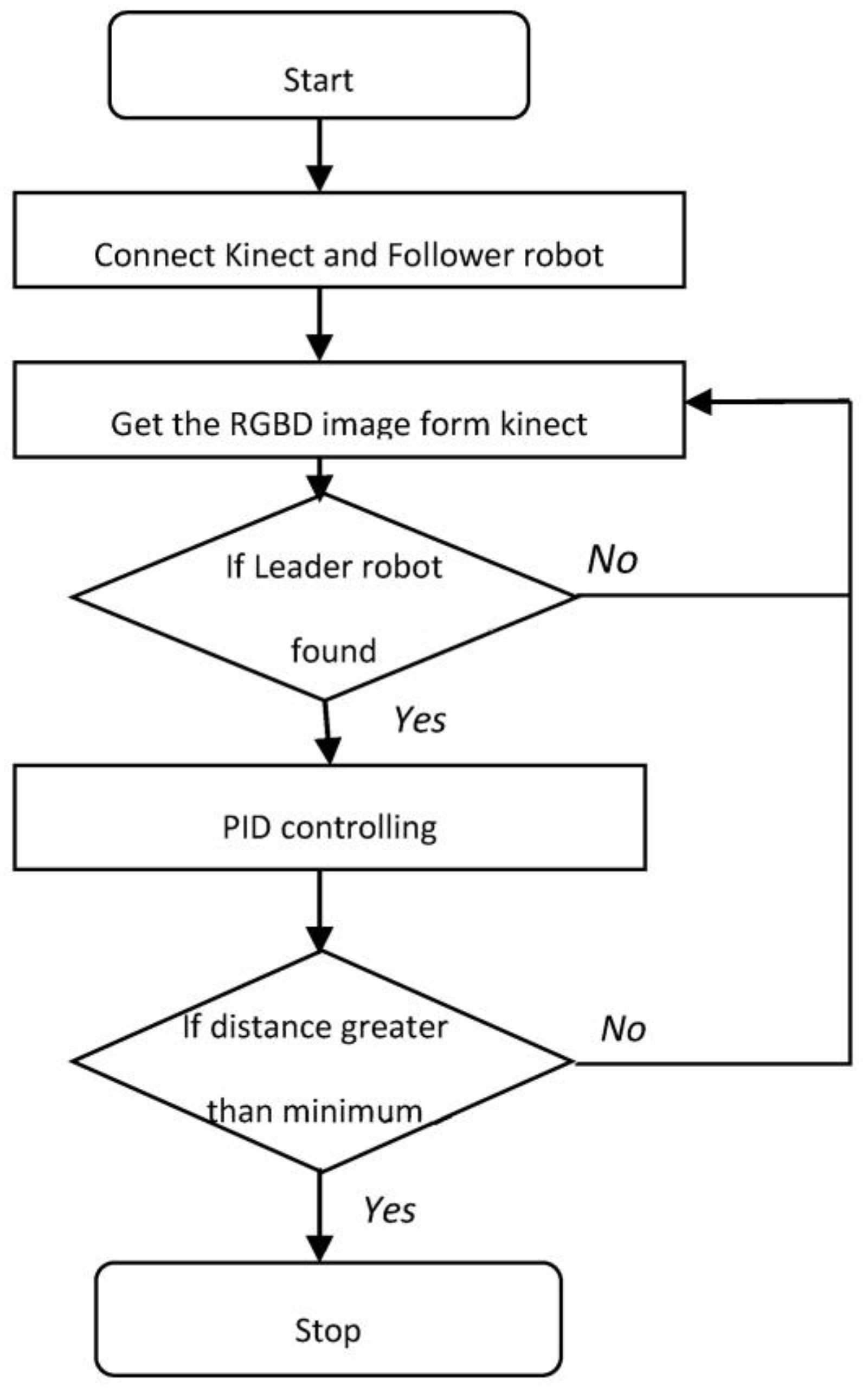
This section discusses the overall approach. First, we have to move the master robot and the follower robot then follows the master robot. Figure 1 shows the working principle of the tele-operated master robot. Figure 2 shows the total working of the follower robot.
As is shown in Figure 1, the master robot receives instructions through Bluetooth communication from the android mobile by the user. If the received commands are valid, the master robot is moved by the actuators. If no command is received from the user, the robot stops.
The aim of the follower robot is to follow the master robot by recognizing it through the color filtering. After finding the master, the follower calculates the master robot’s x, y, and z coordinates from the RGBD Kinect image [13]. Here, x, y, and z are the coordinates in the reference frame of the Kinect sensor, which is mounted on the follower robot (SMART). If the z value is more than a certain threshold, using the x, y, and z differential values, the wheel velocities are found through the PID controller. Using these velocities, the follower robot follows the master robot.
2.1. Tele-Operating the Master Robot
The master robot is the tele-operated robot which is designed based on Arduino and the HC-05 Bluetooth module. An Android app connects to the HC-05 Bluetooth module. The information received through the Bluetooth will be read by the Arduino board. The Arduino board compares the received values with the teleoperation robot and sends inputs to the L293D motor driver. The motor driver amplifies the signals and gives motion to the motors. Since we are using an HC-05 Bluetooth module, the master controlling range is approximately 10 m. The working philosophy is given in Figure 3a. The master robot is covered with green colored paper, as shown in Figure 3b, so that it can be recognized by the follower robot by using color filtering. According to the environment, it is possible to change the color of the follower robot.
2.2. Vision
The vision module is a part of the follower robot and is responsible for recognizing and locating the master robot. The master robot is assumed to be of a single color, not otherwise present in the environment. This is achieved by wrapping the master robot with colored paper. A color detection filter is used, which is a median filter whose ranges are calibrated prior to the start of the experimentation. The master robot is recognized as the single largest block, with a size greater than a certain threshold. The center of the area of the block is taken as the center of the robot. Let <u, v> be the detected master robot in the camera’s frame of reference. This needs to be used to control the robot using the angle to the master in the follower robot’s frame of reference. The derivation of that angle is based on transformations.
Let the calibration matrix of Kinect be given by Equation (1).
where fx and fy are the focal points with respect to the X-axis and Y-axis, and cx and cy represent the center of the projection with respect to the X-axis and Y-axis.
The image coordinates are , denoting the position of the master robot in the image coordinate axis system. The position of the master in Kinect’s frame of reference is . The conversion is given by Equation (2). Here, z is directly obtained as the depth value from the Kinect.
As shown in Figure 4, consider a coordinate axis system centered at the follower robot with the axis facing the direction of motion of the robot, as the ground, and being located vertically above. Let the master be located at a direction of θ in this coordinate system. Let the coordinate axis system of the follower robot be centered at the Kinect, since the Kinect is horizontally mounted on the follower robot. Practically, there will be a small translation factor between the coordinate axis system of the Kinect and the center of mass of the follower robot, which barely affects the steering mechanism, while the speed control has an equivalent parameter that can be tuned. The calculation of the angle to the master robot is given by Equations (3)–(6). The superscript F denotes the follower (Kinect) frame of reference, while the sub-script L stands for the leader robot.
The follower moves so as to keep θ as close as possible to 0, and so as to maintain a constant distance from the master robot.
2.3. PID Control
The control of the robot may be divided into a steering control and a speed control. First, the steering control is discussed. The steering control uses a Proportional-Integral-Differential (PID) controller, which is a control loop feedback mechanism. In PID control, the current output is based on the feedback of the previous output, which is computed so as to keep the error small. The error is calculated as the difference between the desired and the measured value, which should be as small as possible. A correction is applied whose numeric value is based on the sum of three terms, known as the proportional term, integral term, and derivative term. Such a control scheme is used to control the differential wheel drive follower mobile robot, which is a highly nonlinear multi-input/multi-output system. Using PID, the velocities of two differential wheels are found. The derivation formulas of the two velocities are given in Equations (7)–(10). Here, , and represent the proportional, integral, and differential terms, respectively.
where ω is the angular speed or the steering control input, is the proportional constant, is the integral constant, is the differential constant, and is the angle between the follower and master robots.
The speed control of the robot takes as error, the distance between the leader and the follower. The follower should not follow the master very closely as this is not socially acceptable and because the sudden turns would cause risks due to the uncertain movement of the leader. Further, the distance cannot be very large as the follower may easily lose contact with the leader robot. Hence a comfortable threshold distance () is to be maintained from the leader. The input velocity is given by Equation (12), where d is the current distance between the master and the slave robots.
The linear (v) and angular (ω) speeds are used to compute the speeds of the two wheels of the differential wheel drive follower robot, given by (13) and (14).
where r is the half distance between two wheels, is the velocity of the first wheel, and is the velocity of the second wheel.
3. Results
3.1. Tele-Operation of the Master Robot
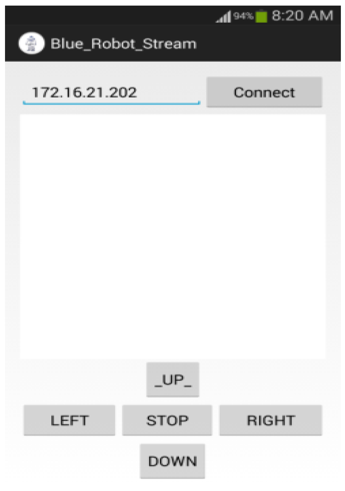
Our android application that we have designed for the Bluetooth communication of the robot is used to check the tele-operation capability of the master robot. We only control the master robot with this application. This application has a special feature which can be used to live stream the master robot, and we can control it. This application is designed on the platform of eclipse android SDK. This is connected to the robot’s HC05 Bluetooth module and sends the user commands. The application is shown in Figure 5.
3.2. Simulation Results
We first present the results of the control module. Before applying the control algorithm on a physical robot, simulations using a custom built simulator had to been done. Using this, we checked whether the work was feasible or not, and if it was feasible, it could then be implemented on a physical robot. In the simulation setup, we took all units to be similar to the physical setup area and operated the robots with speeds similar to the speed of the master and follower robots. We considered a 3 × 3 m region as where the real robot moves, and correspondingly, 100 × 100 pixels in the simulation are taken as being equivalent to the real environment. The master robot speed is 5 cm per second in practice, so in the simulation, we made it 1.67 pixels per second. Additionally, follower robot speed should not surpass 1.67 pixels per second, so we used a threshold value of 1.67 pixels per second.
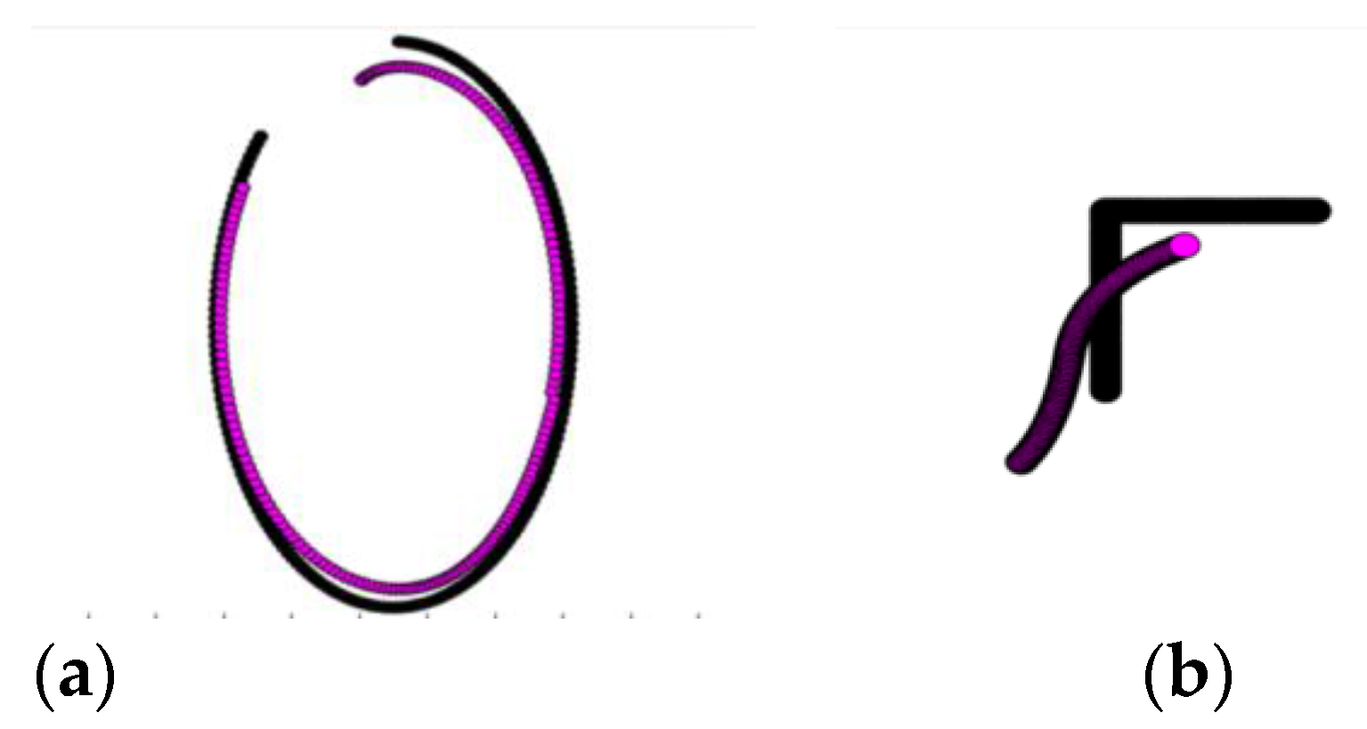
The simulations were done on shapes like a circle, line, ellipse, and square for the P controller, PD controller, PI controller, and PID controller. The results of selective simulations are shown in Figure 6. In all simulations, the constants are taken as kp = 23.33 (), kd = 1.67 , and kI = 0.033 . In all cases, the leader was kept sufficiently ahead of the follower. The black one is the leader robot and the pink one is the follower robot. The results are also available as a video at [14].
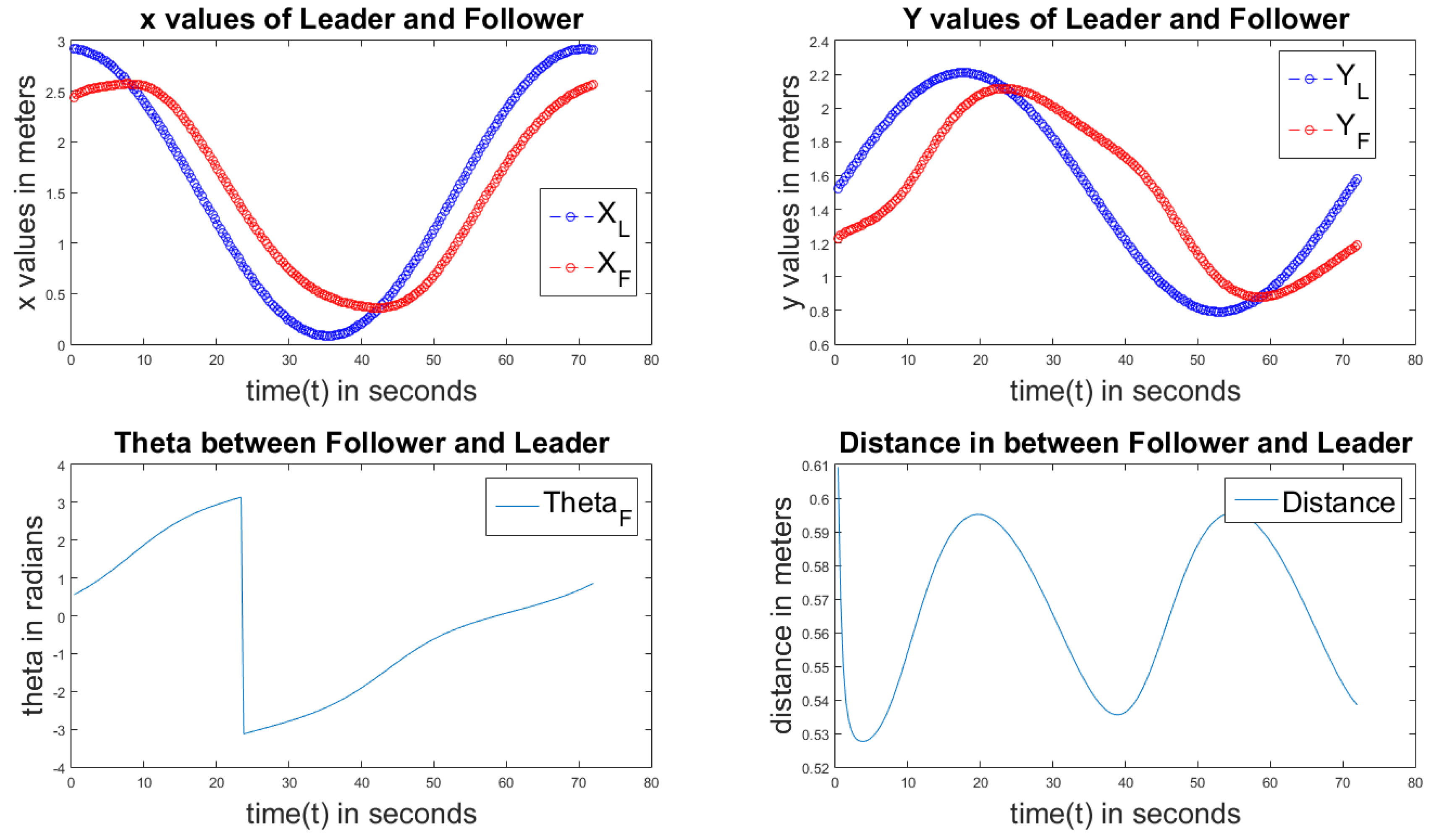
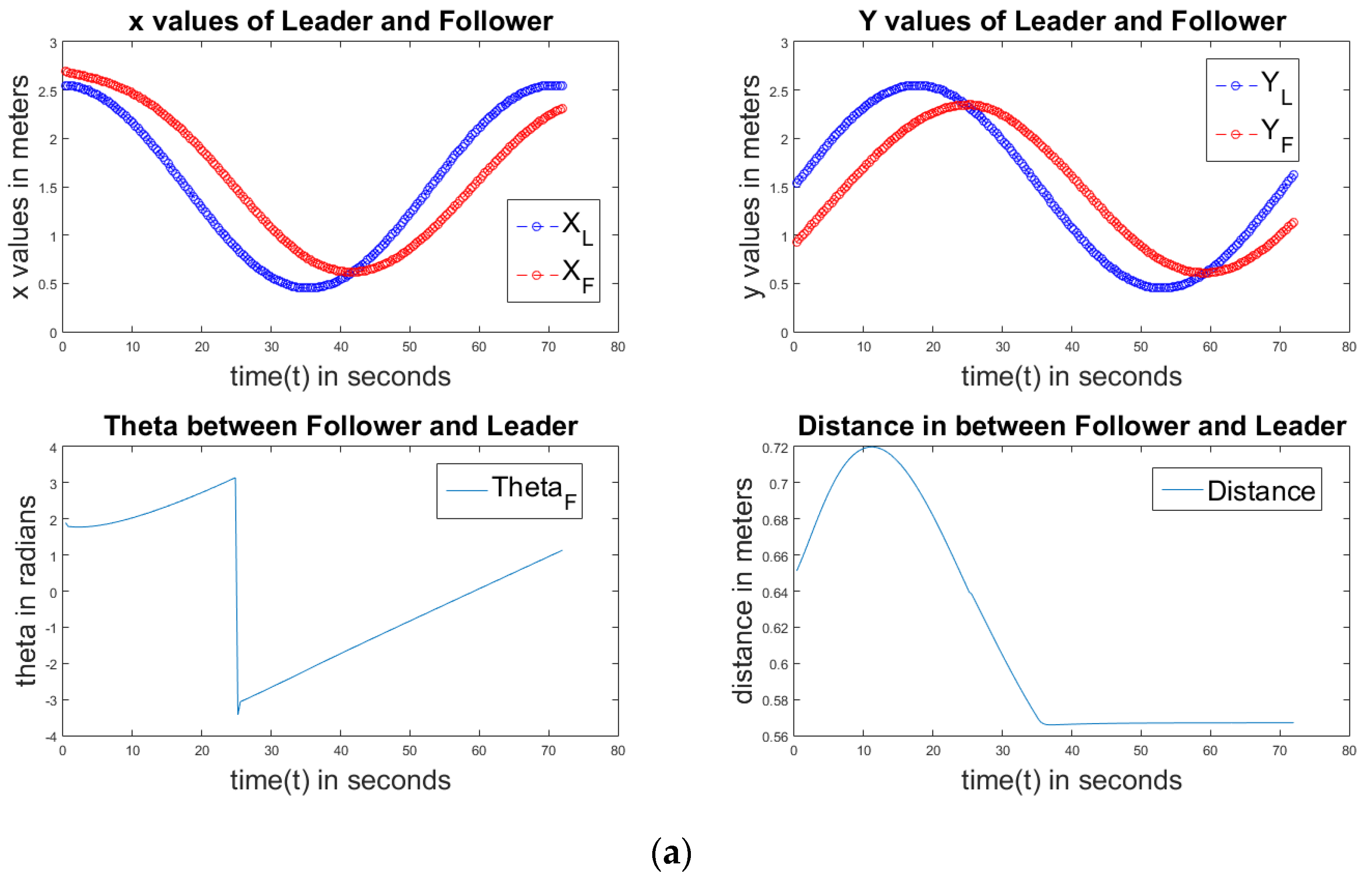
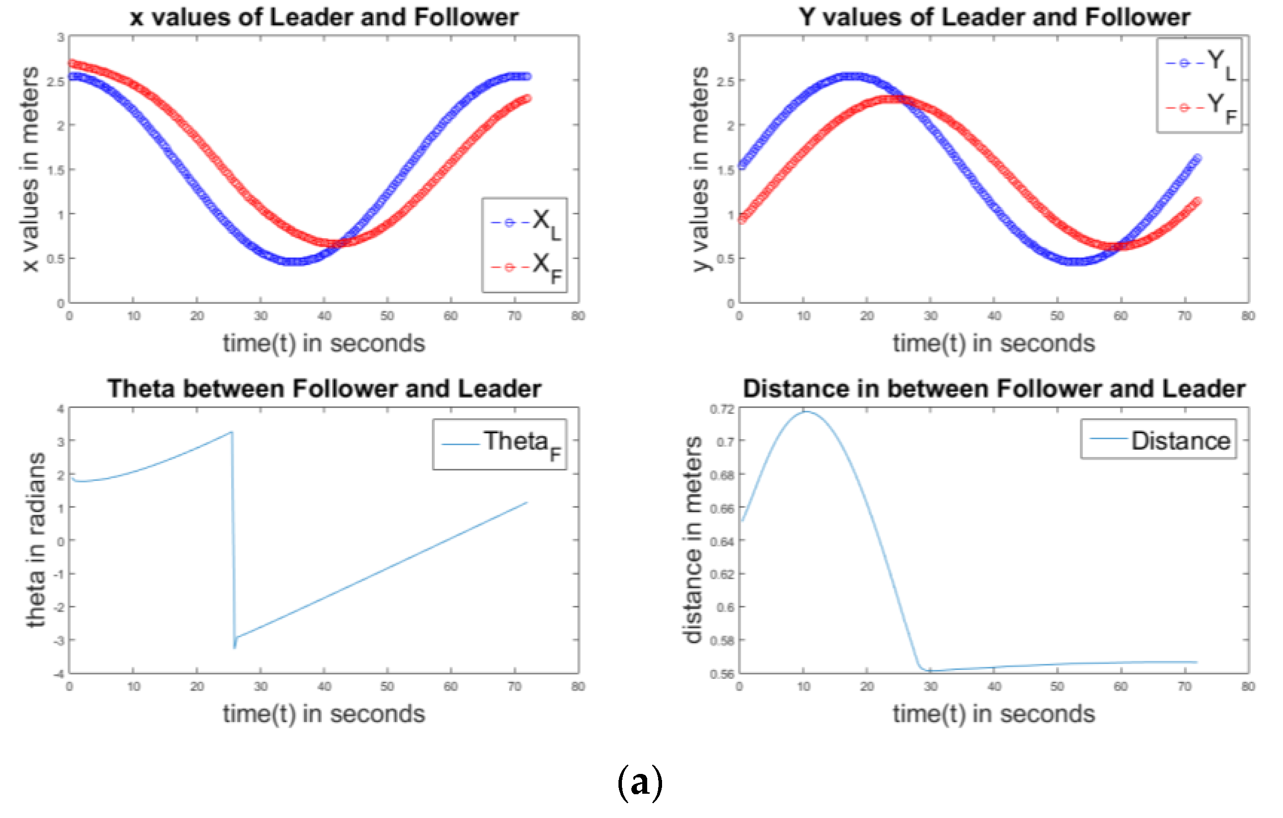
Figure 7 shows the results on the use of a P controller of the circular path. The first sub-plot compares the X values of the follower and the master robots. The second sub-plot compares the Y values of the follower and the master robots. The third sub-plot indicates the error value and how it changes in the simulations. The last sub-plot indicates the distance between the master robot and the follower robot. We can observe that after reaching the threshold value, the distance is constant. It must be noted that the problem is not controlling a system with a static goal point, in which case the system eventually reaches the goal point with a small error. The master robot acts as a goal for the following robot. The master robot keeps moving abruptly, and therefore, from a control perspective, the goal point keeps changing, making sure that no convergence to a zero error occurs. The error metric is the correlation between the trajectories of the master and the slave. This further needs account for the fact that in the simulations, the master robot can follow trajectories like a square, which do not obey the non-holonomic constraints of the slave robot, and hence, smoothening of the curve is not really an error.
Figure 8 describes the P controller of an elliptical path. The individual sub-plots are as explained earlier. From the first and second sub-plots, we can observe the elliptical path. The last graph is not constant; it shows that in the elliptical path, the follower robot can’t move with a constant speed.
Figure 9 displays the P control of a linear path. As is explained in the previous graphs, the sub-plots are in the same order. From the first two graphs, we can observe the approximate linear path. Here, the error is almost constant because it is a linear path. The distance between the follower and master is also near to constant with less variation from 0.5 m to 0.55 m in 80 s because no fluctuations are observed in the linear path.
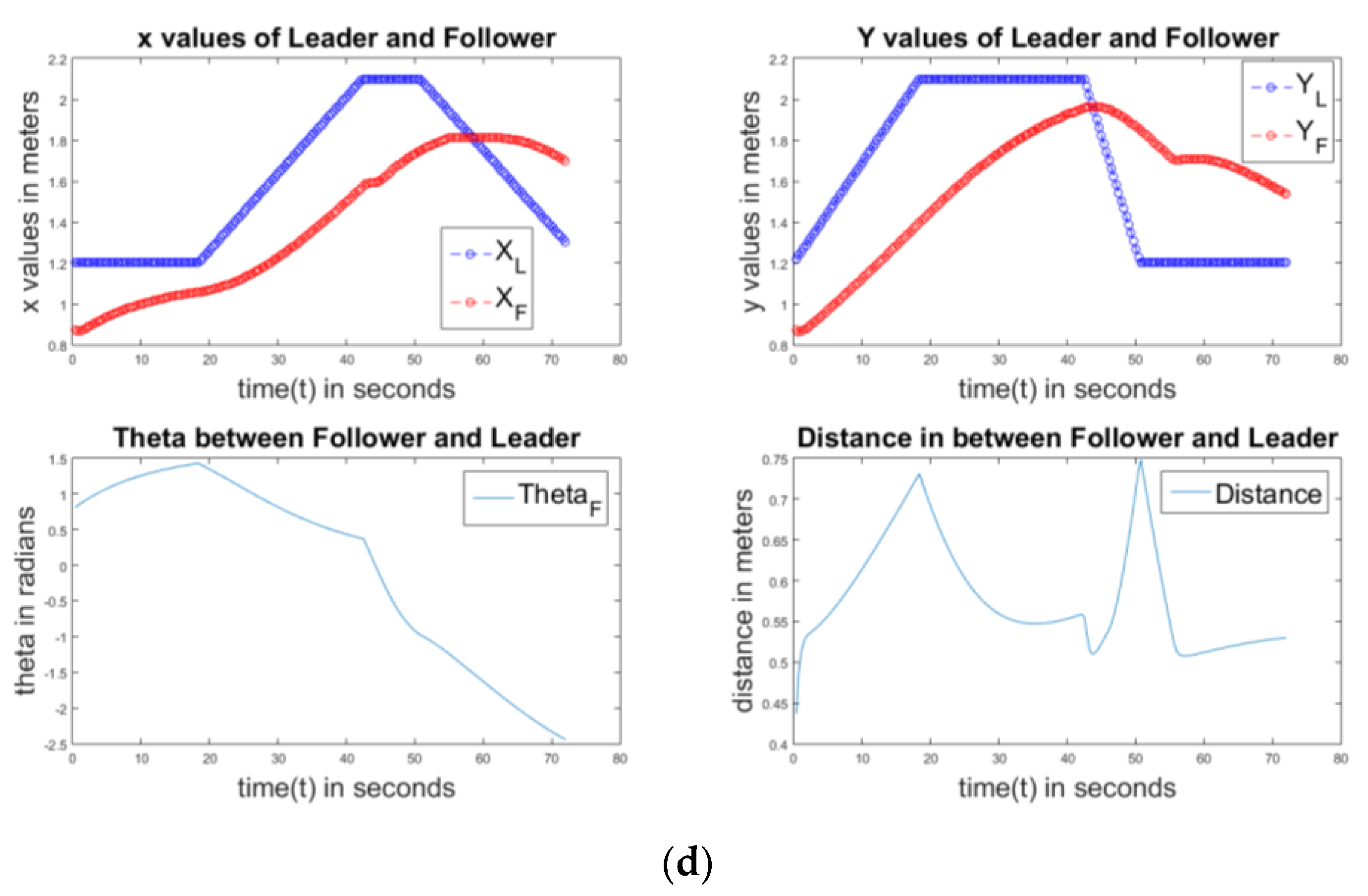
Figure 10 describes the P controller of the square path. The sub-plots are again in the same order. We can observe more fluctuations of X and Y than in the circular, elliptical, and linear paths, because when the master is following a square path at the edges, the follower tries to follow in the curved path. From the last graph, we can observe that no constant distance is maintained in between them.
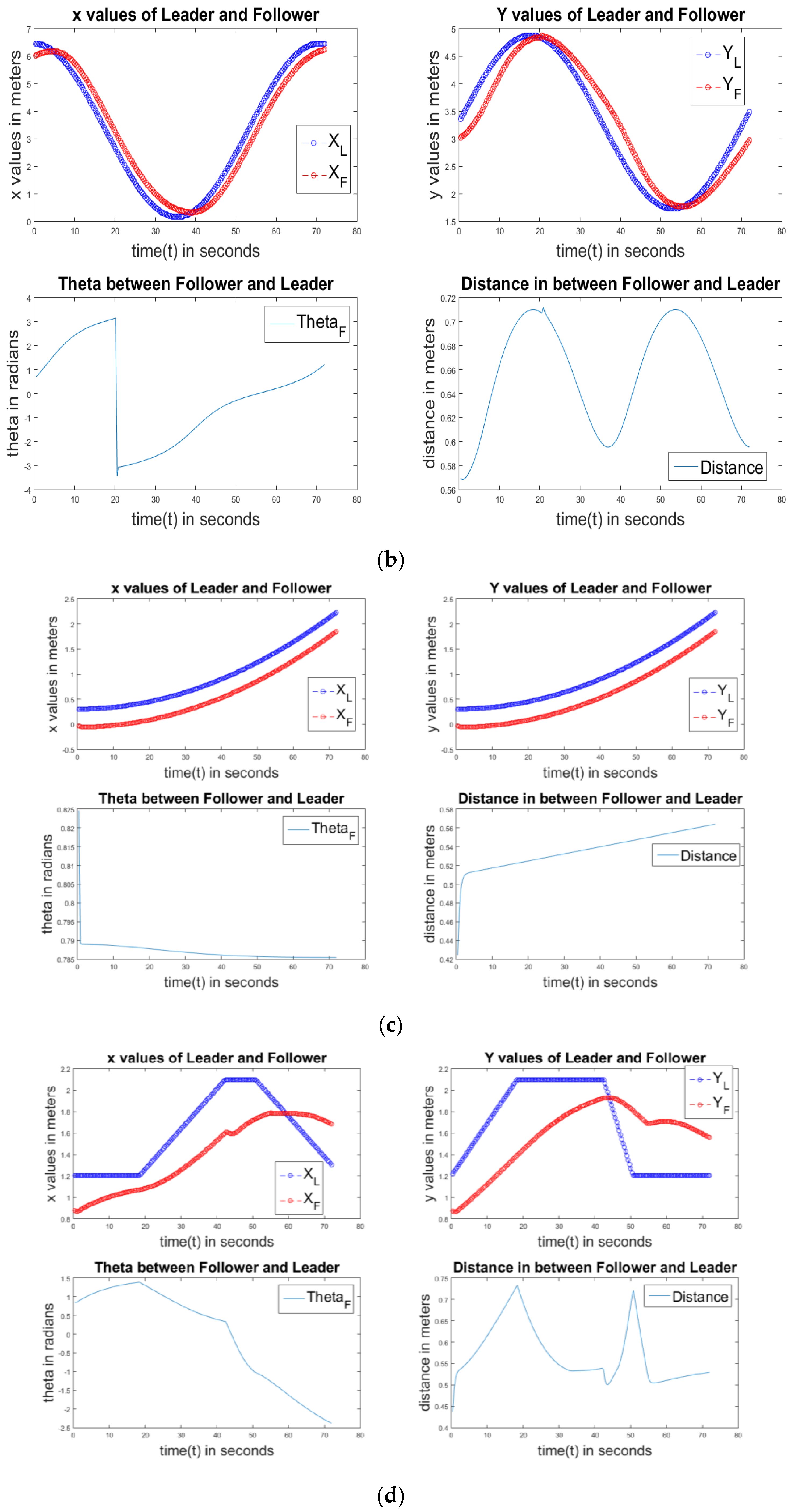
Figure 11a–d show the PD controller of circle, ellipse, linear, and square paths, respectively. All of them also have the same properties as the P controller. Simulations are completed with all P, PD, PI, and PID controllers to find out which one is the best controller.
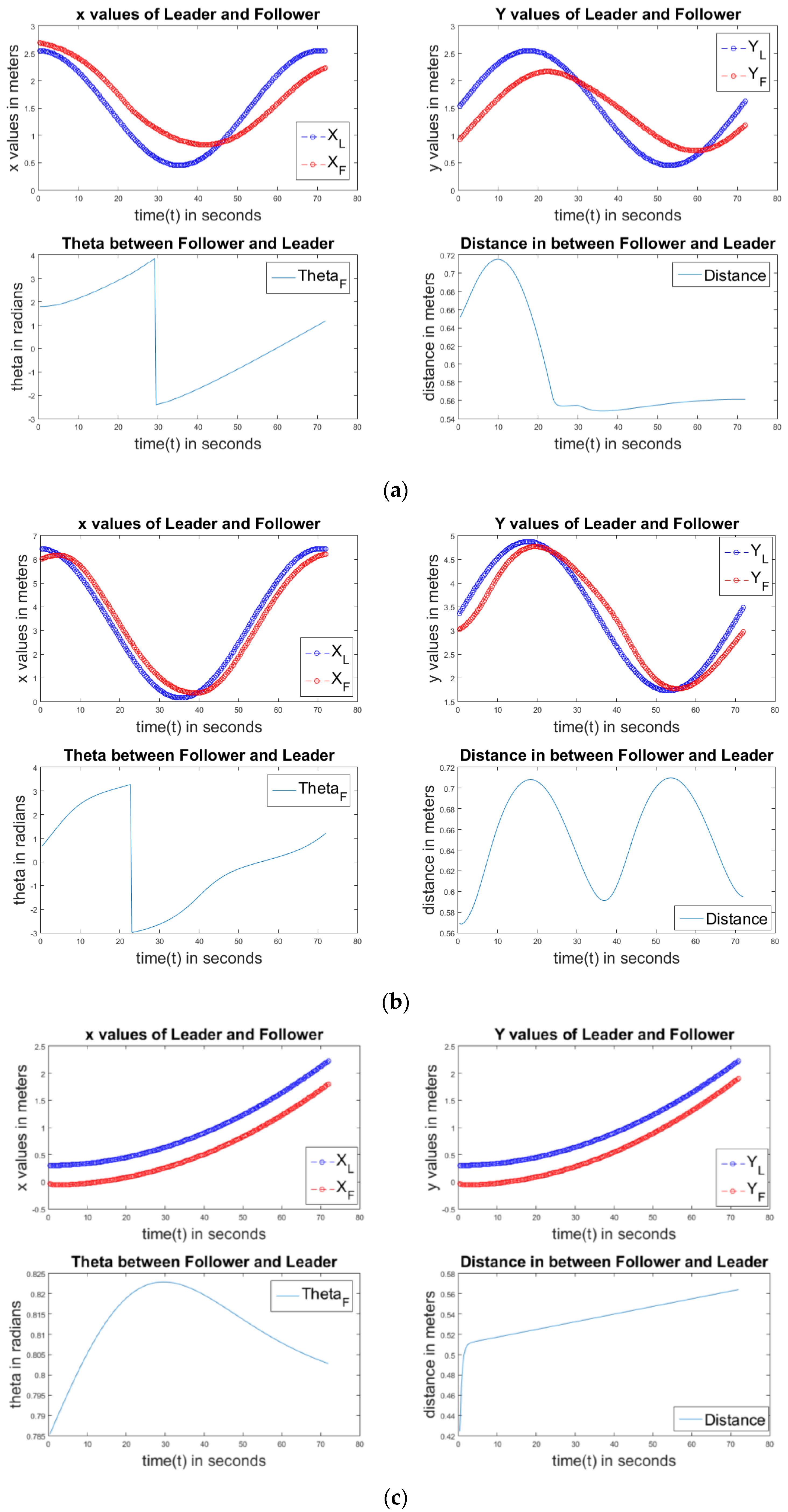
Figure 12a,b show the results of a PI controller of circle, ellipse, linear, and square paths. All four graphs show similar properties like the P and PD controllers. Figure 13a,b show the results of the PID controller of circle, ellipse, linear, and square paths. The PID controller also shows similar properties in all graphs like the P, PD, and PI controllers.
3.3. Analasis of PID Control
In the practical observations, we first applied P, PD, PI, and PID controllers, rather than directly applying the PID controller. In the observations, when we applied the P controller, the follower robot received some jerks in its motion. When using the PD controller, those jerks decreased in number, and when using the PI controller, the frequency of jerks also decreased comparatively, but the follower didn’t receive a smooth motion. When using the PID controller, the jerks are decreased to a greater extent than when employing P, PD, and PI controllers, and the follower robot moved almost as accurately as the master. Among all of the controllers, PID resulted in the least amount of errors. In the simulation, we also acquired results with very slight errors for all controllers, but among them, PID is the best.
The most difficult part in PID control is tuning the , and values. By tuning the physical robot and in simulations, we got , and values of 0.7 , 0.05 , and 0.001 , respectively. For these constant values of PID, our follower robot follows the leader most accurately.
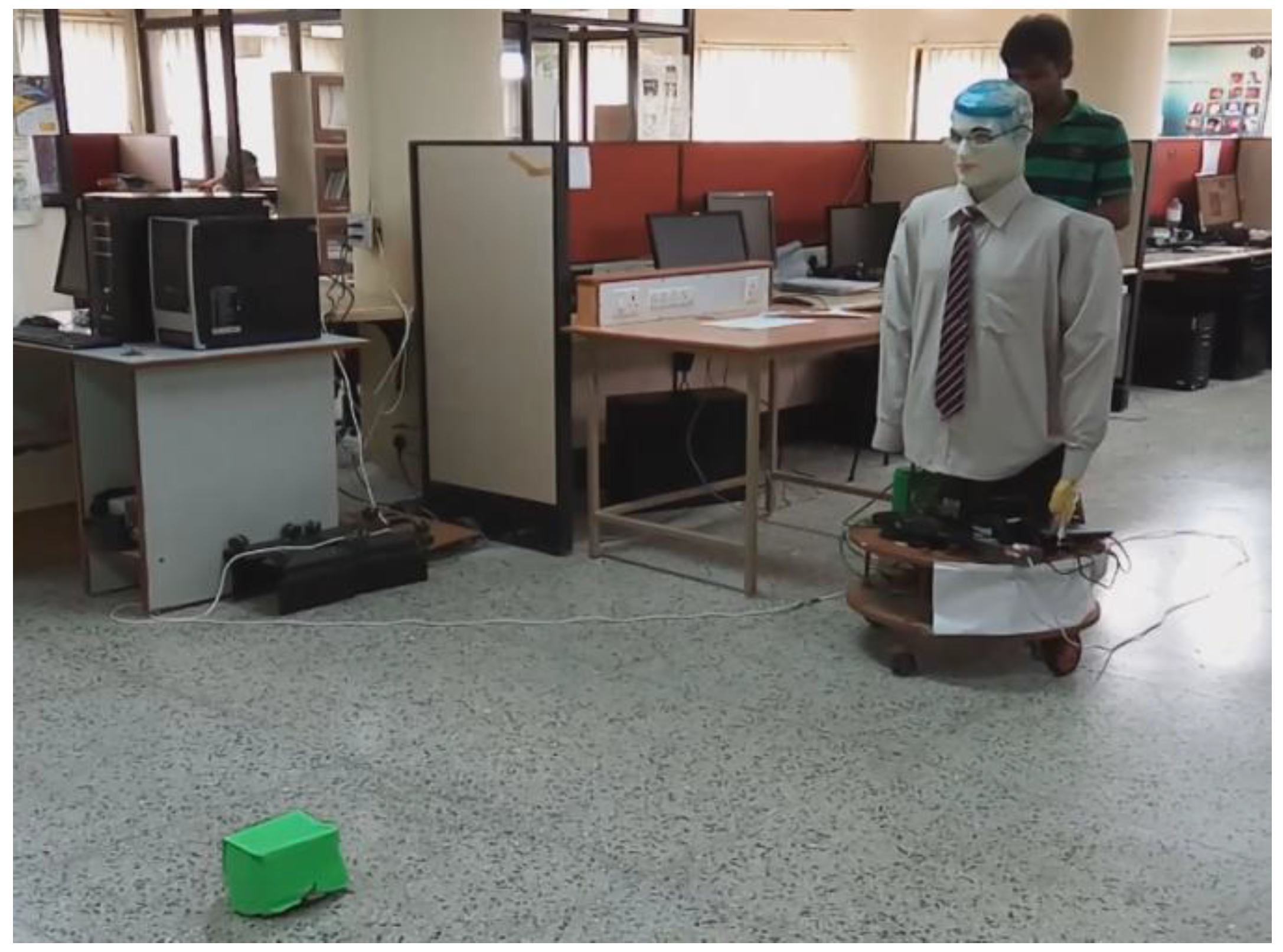
3.4. Results on the Real Robots
After the simulation, the experiments are repeated for a physical setup consisting of the two real robots. The results are shown in Figure 14. The results can be better visualized as a video, which is available in [14]. In the video, the green robot is the master robot and the robot on the back side is the differential wheel follower robot (known as SMART). As discussed earlier, the master robot was designed as a teleoperation robot with Arduino, a Bluetooth module, and an android mobile. The follower robot was only designed on Arduino, but the entire process was conducted on the laptop on the python platform. It takes an RGBD image from Kinect, which is mounted in front of it. Through a python arduino simulation, the velocity of the two motors is sent to the follower robot. Image processing and the PID controller are controlled on the laptop on the python open cv platform.
4. Conclusions
In this paper, robot following based on computer vision and PID control for a differential wheel robot was presented. For this, we designed two robots; one worked as a master and was controlled by the user through manual control based on Android and Bluetooth. The master consisted of an Arduino UNO board and HC05 Bluetooth module. The second robot worked as a follower robot. We used the SMART robot of the IIITA Robotics laboratory as a follower. It was somewhat bigger and more convenient to hold Kinect, a laptop, and Arduino. By using Kinect for the master robot, we produced an RGBD image, which was used to identify and localize the master robot and the master robot was followed by the follower robot using a PID controller.
Through our experiments, it was shown that the follower robot could follow the master robot with minimum errors. First, we performed the simulation work, identified the minimum error values (of angle θ and distance (d), and then implemented the physical model according to the simulation values. The physical model also worked correctly with minimum error values.
In this project, we did not consider any obstacles in its path. However, in reality, there will be some static or dynamic obstacles in the path. In our case, the follower robot was not designed to stop or to take another path without missing the master robot. Therefore, our future work aims to overcome obstacles as well. Using Kinect, we can find obstacles from the depth values. After finding those obstacles with the help of motion planning algorithms we will design obstacle-free paths. Further, the aim is to use Extended Kalman Filters for tracking the master and slave robots so that the system can work even if the master robot is not in sight and to eliminate any errors.
Acknowledgments
The work is sponsored by the Indian Institute of Information Technology, Allahabad through its Summer Research Internship Program initiative.
Author Contributions
C.S.P. and R.K. designed the algorithms. C.S.P. did the development and experimentation of the work. C.S.P. and R.K. wrote the paper.
Conflicts of Interest
The authors declare no conflict of interest.
References
- Yoshimi, T.; Nishiyama, M.; Sonoura, T.; Nakamoto, H.; Tokura, S.; Sato, H.; Ozaki, F.; Matsuhira, N. Development of a Person Following Robot with Vision Based Target Detection. In Proceedings of the 2006 IEEE/RSJ, International Conference on Intelligent Robots and Systems, Beijing, China, 9–15 October 2006; pp. 5286–5291. [Google Scholar]
- Shah, H.N.; Ab Rashid, M.Z.; Tam, T.Y. Develop and Implementation of Autonomous Vision Based Mobile, Robot Following Human. Int. J. Adv. Sci. Technol. 2013, 51, 81–91. [Google Scholar]
- Khoshelham, K.; Elberink, S.O. Accuracy and Resolution of Kinect Depth Data for Indoor Mapping Applications. Sensors 2012, 12, 1437–1454. [Google Scholar] [CrossRef] [PubMed]
- Fang, Z.; Zhang, Y. Experimental Evaluation of RGB-D Visual Odometry Methods. Int. J. Adv. Robot. Syst. 2015, 12, 26. [Google Scholar] [CrossRef]
- Gavrila, D.M.; Philomin, V. Real-time object detection for smart vehicles. In Proceedings of the IEEE International Conference on Computer Vision, Kerkyra, Greece, 20–27 September 1999; pp. 87–93. [Google Scholar]
- Martinez, J.L.; Pozo-Ruz, A.; Pedraza, S.; Fernhdez, R. Object Following and Obstacle Avoidance Using a LaserScanner in the Outdoor Mobile Robot Auriga-α. In Proceedings of the 1998 IEEE/RSJ, International Conference on Intelligent Robots and Systems, Victoria, BC, Canada, 17 October 1998; pp. 204–209. [Google Scholar]
- Breivik, M.; Fossen, T.I. Guidance-based Path Following for Wheeled Mobile Robots. IFAC Proc. Vol. 2005, 38, 13–18. [Google Scholar] [CrossRef]
- Jamkhandikar, D.; Mytri, V.D.; Shahapure, P. Object Detection and Tracking in Real Time Video Based on Color. Int. Eng. Res. Dev. 2014, 10, 33–37. [Google Scholar]
- Islam, S.M.R.; Shawkat, S.; Bhattacharyya, S.; Hossain, M.K. Differential Drive Adaptive Proportional-Integral-Derivative (PID) Controlled Mobile Robot Speed Synchronization. Int. J. Comput. Appl. 2014, 108, 5–8. [Google Scholar]
- Sharma, A.; Verma, R.; Guptaand, S.; Kaur Bhatia, S. Android Phone Controlled Robot Using Bluetooth. Int. J. Electron. Electr. Eng. 2014, 7, 443–448. [Google Scholar]
- Eshita, R.Z.; Barua, T.; Barua, A.; Dip, A.M. Bluetooth Based Android Controlled Robot. Am. J. Eng. Res. 2016, 5, 195–199. [Google Scholar]
- Saini, A.K.; Sharma, G.; Choure, K.K. BluBO: Bluetooth Controlled Robot. In Proceedings of the National Conference on Knowledge, Innovation in Technology and Engineering, Chhattisgarh, Raipur, India, 10–11 April 2015; pp. 325–328. [Google Scholar]
- Zalevsky, Z.; Shpunt, A.; Maizels, A.; Garcia, J. Method and System for Object Reconstruction. U.S. Patent, 20,100,177,164 A1, 15 July 2010. [Google Scholar]
- Video Results. Available online: https://www.youtube.com/playlist?list=PL3c2Sta-bBqCpREFB27ReRXcmVRPruW6v (accessed on 20 April 2017).
Figure 1.
Motion of the tele-operated master robot.
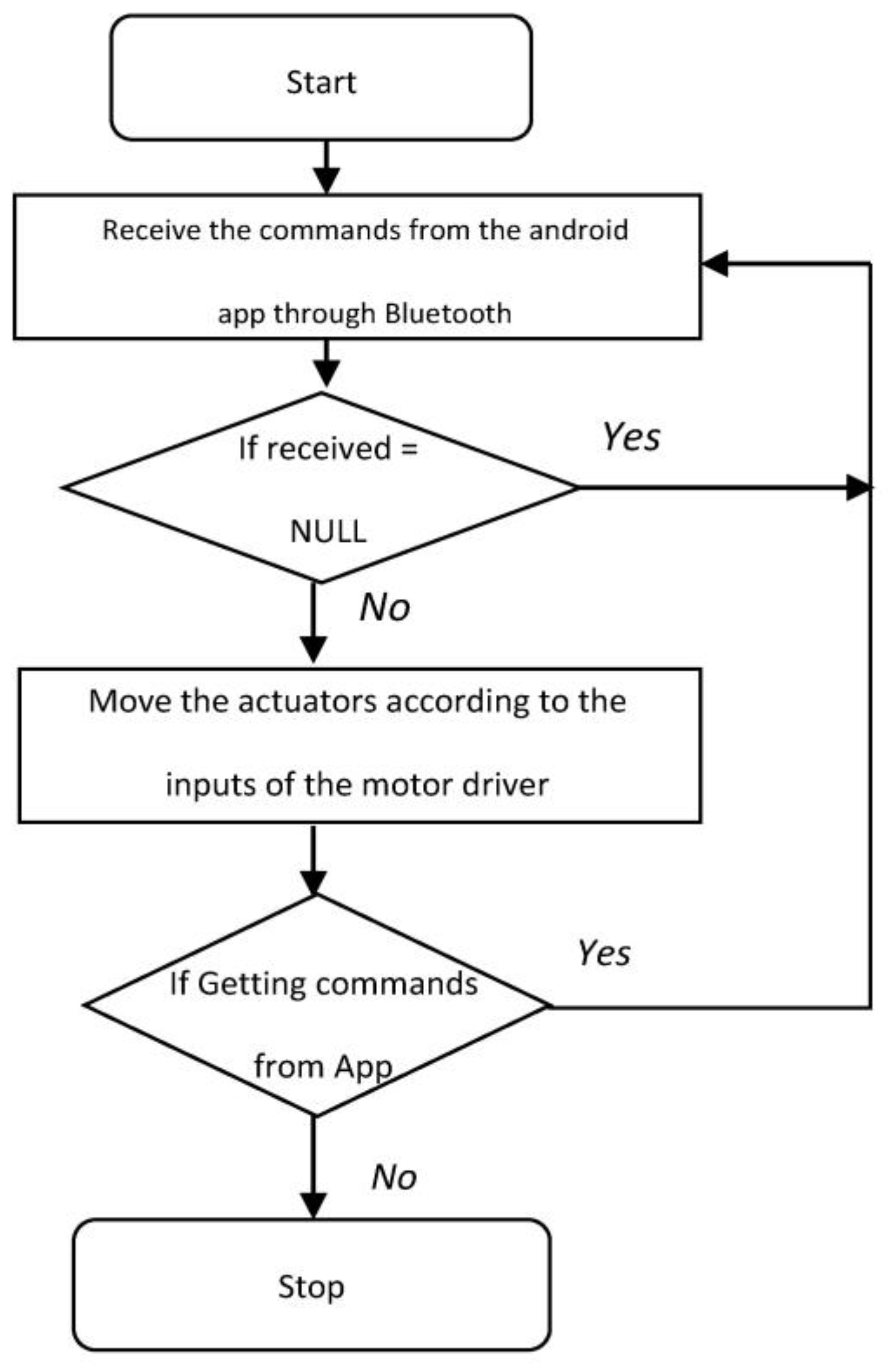
Figure 2.
Motion of the follower robot.

Figure 3.
(a) Tele-operation of the master robot; (b) The master robot.
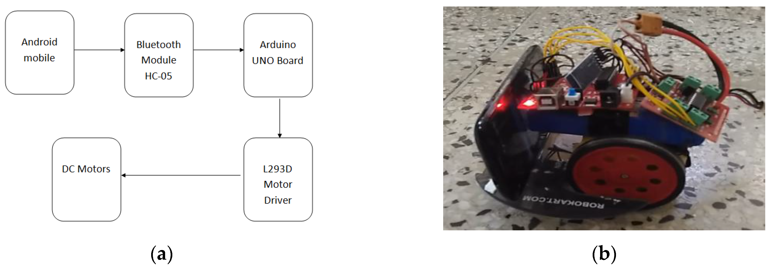
Figure 4.
Calculation of the angle to the master robot.
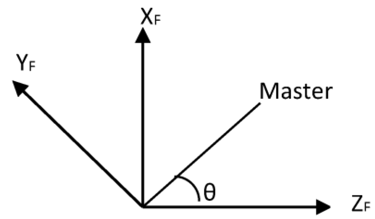
Figure 5.
Android application for controlling the master robot.

Figure 6.
Results for controller on simulations: (a) In circular path; (b) In square path.

Figure 7.
P controller of a circle.
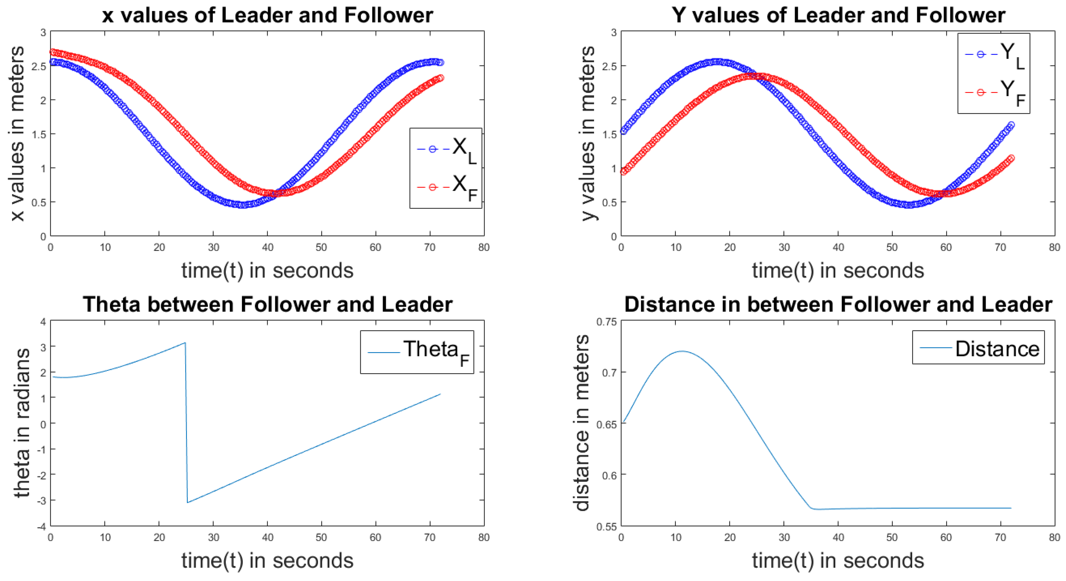
Figure 8.
P controller of an ellipse.

Figure 9.
P controller of a line.
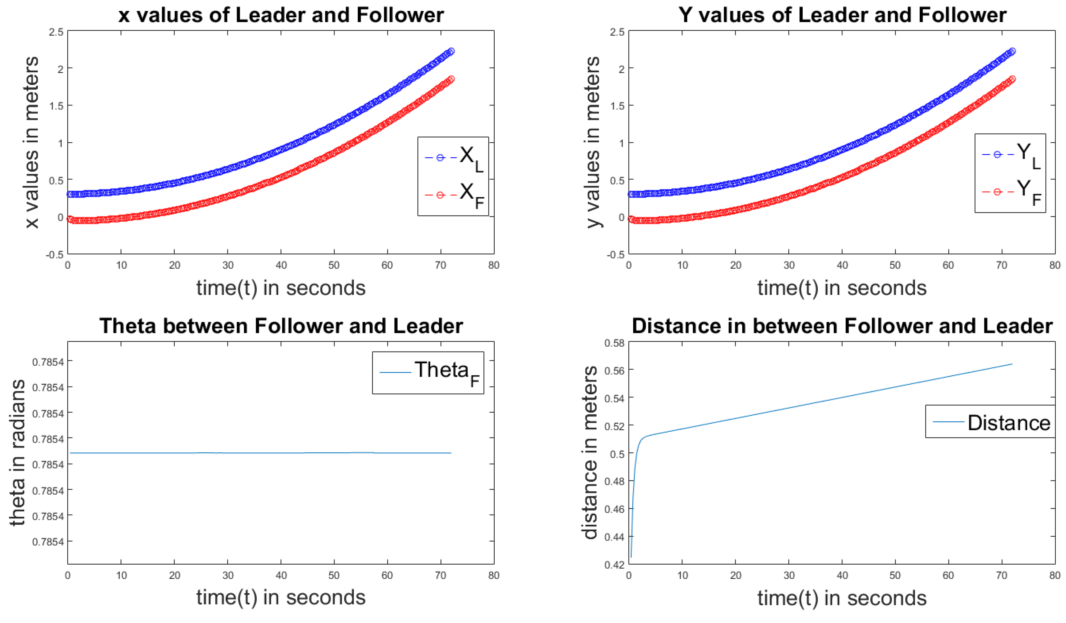
Figure 10.
P controller of a square.
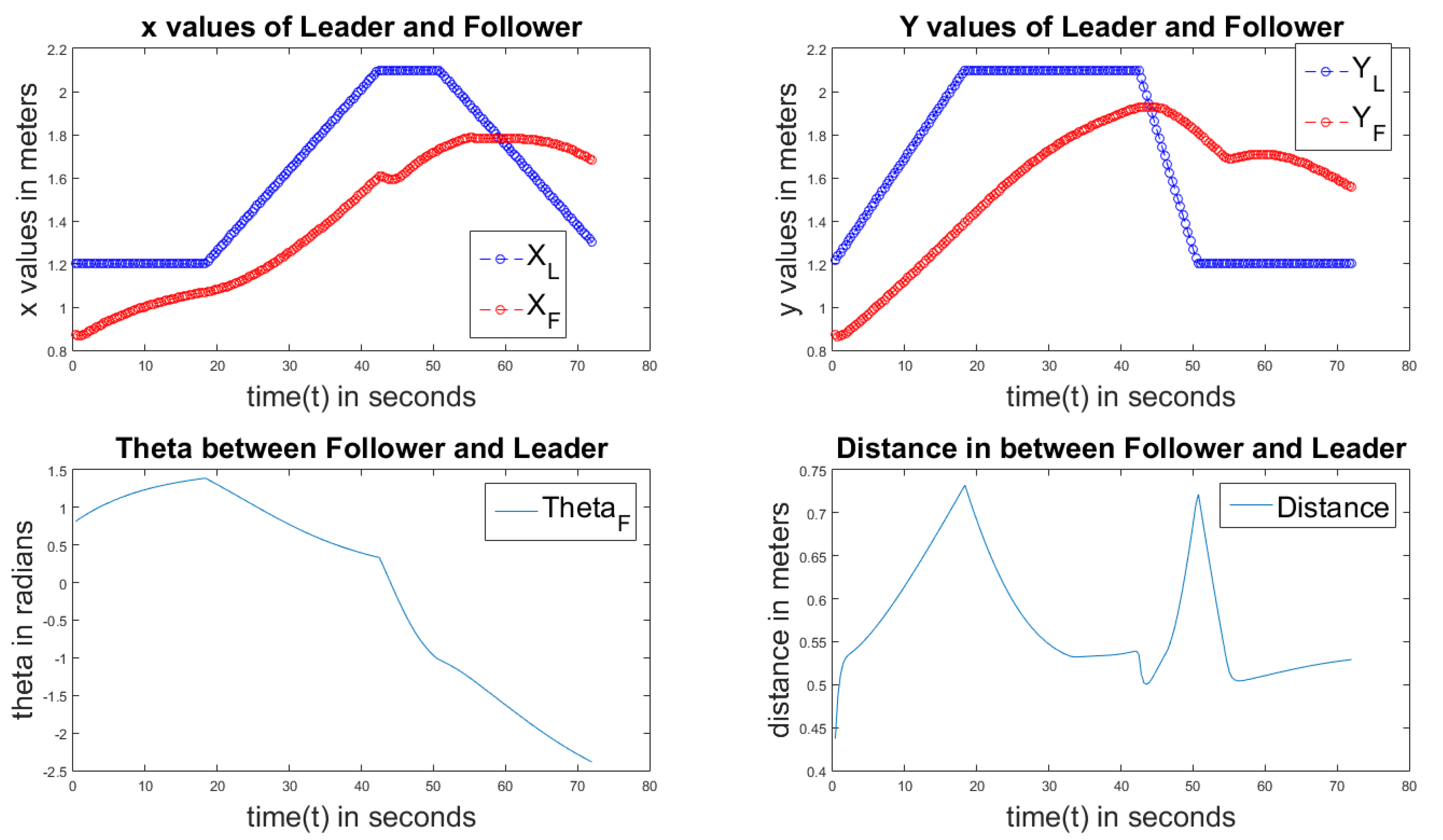
Figure 11.
(a) PD controller of a circle; (b) PD controller of an ellipse; (c) PD controller of a line; (d) PD controller of a square.
Figure 11.
(a) PD controller of a circle; (b) PD controller of an ellipse; (c) PD controller of a line; (d) PD controller of a square.


Figure 12.
(a) PI controller of a circle; (b) PI controller of an ellipse; (c) PI controller of a line; (d) PI controller of a square.
Figure 12.
(a) PI controller of a circle; (b) PI controller of an ellipse; (c) PI controller of a line; (d) PI controller of a square.


Figure 13.
(a) PID controller of a circle; (b) PID controller of an ellipse; (c) PID controller of a line; (d) PID controller of a square.
Figure 13.
(a) PID controller of a circle; (b) PID controller of an ellipse; (c) PID controller of a line; (d) PID controller of a square.

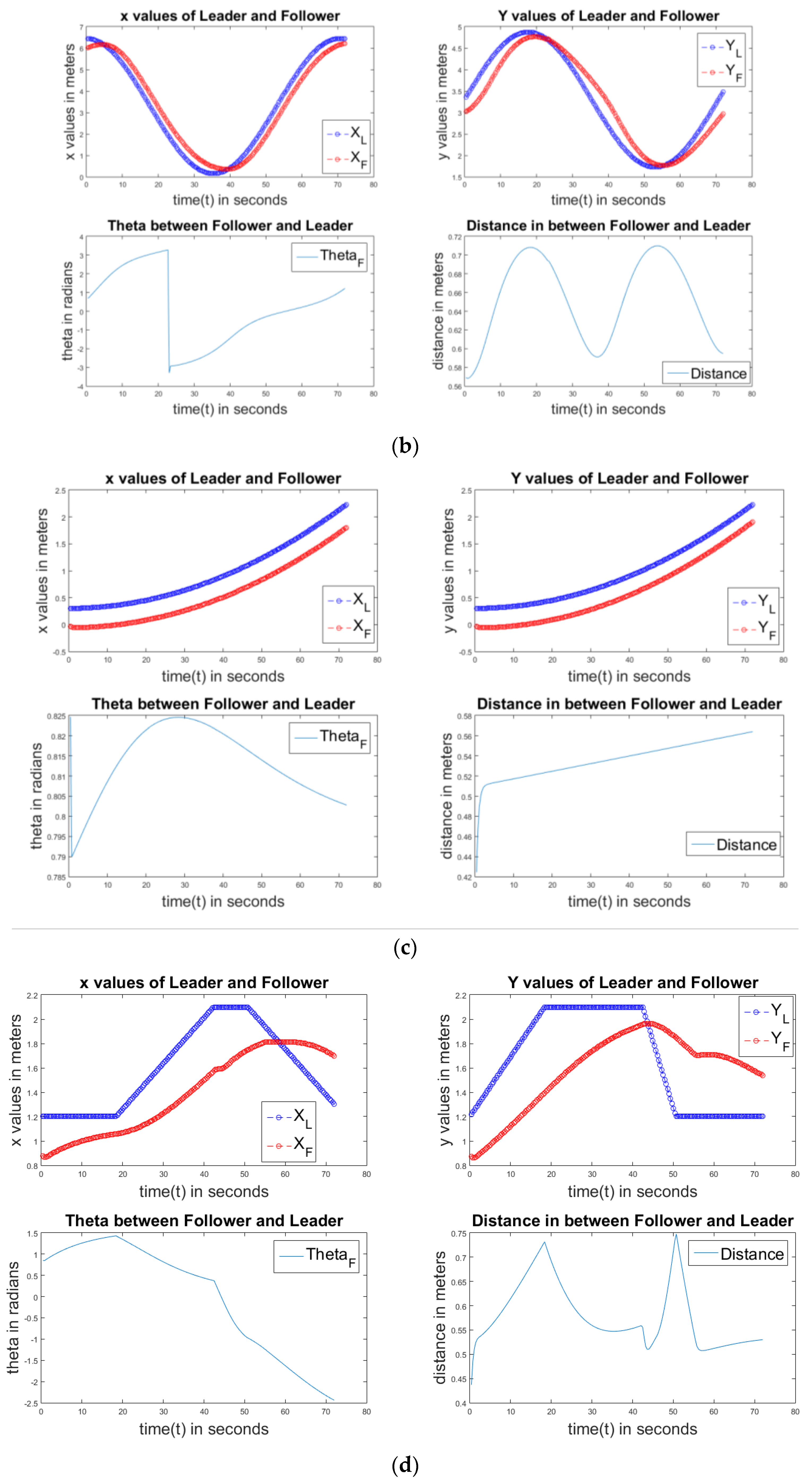
Figure 14.
Results on the physical setup.
© 2017 by the authors. Licensee MDPI, Basel, Switzerland. This article is an open access article distributed under the terms and conditions of the Creative Commons Attribution (CC BY) license (http://creativecommons.org/licenses/by/4.0/).
Share and Cite
MDPI and ACS Style
Pati, C.S.; Kala, R. Vision-Based Robot Following Using PID Control. Technologies 2017, 5, 34. https://doi.org/10.3390/technologies5020034
AMA Style
Pati CS, Kala R. Vision-Based Robot Following Using PID Control. Technologies. 2017; 5(2):34. https://doi.org/10.3390/technologies5020034
Chicago/Turabian StylePati, Chandra Sekhar, and Rahul Kala. 2017. "Vision-Based Robot Following Using PID Control" Technologies 5, no. 2: 34. https://doi.org/10.3390/technologies5020034
Note that from the first issue of 2016, this journal uses article numbers instead of page numbers. See further details here.