Tactile Myography: An Off-Line Assessment of Able-Bodied Subjects and One Upper-Limb Amputee

 , , , and
Abstract
:1. Introduction
Related Work
2. Materials and Methods
2.1. Experimental Setup
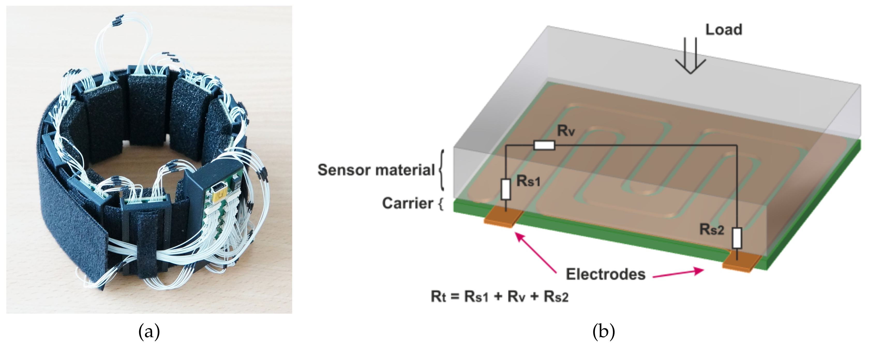
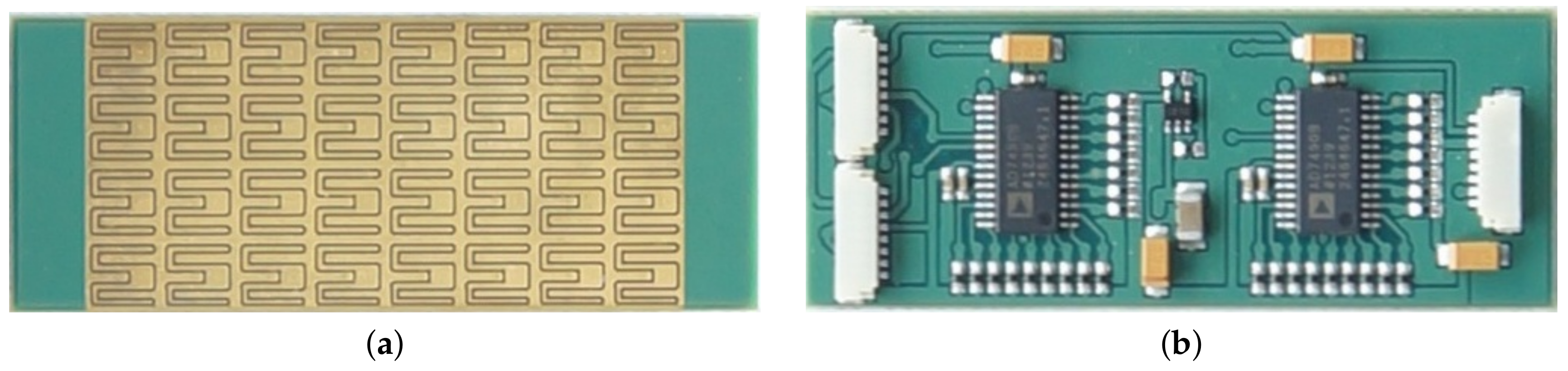
2.1.1. Tactile Bracelet
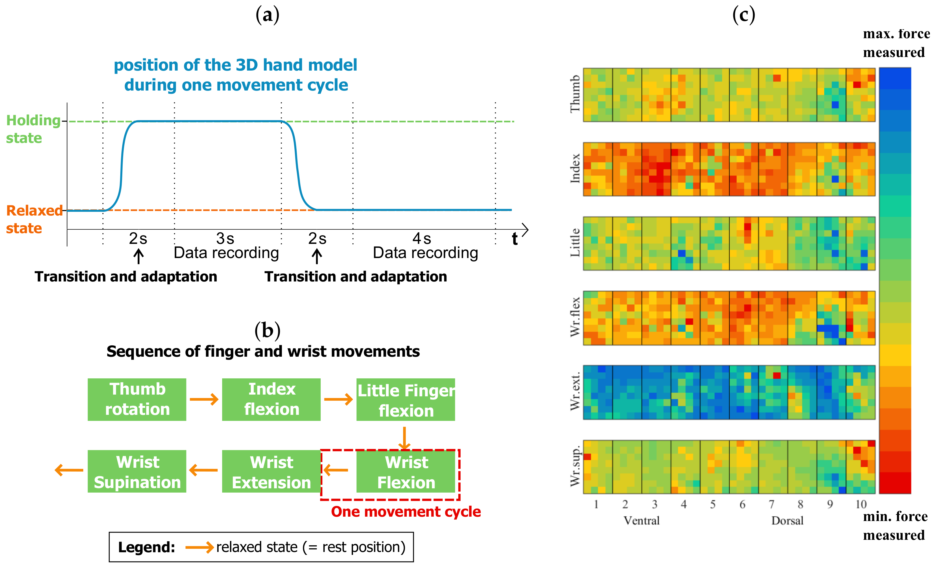
2.1.2. Visual Stimulus
2.2. Participants
2.3. Experimental Protocol
2.4. Data Analysis
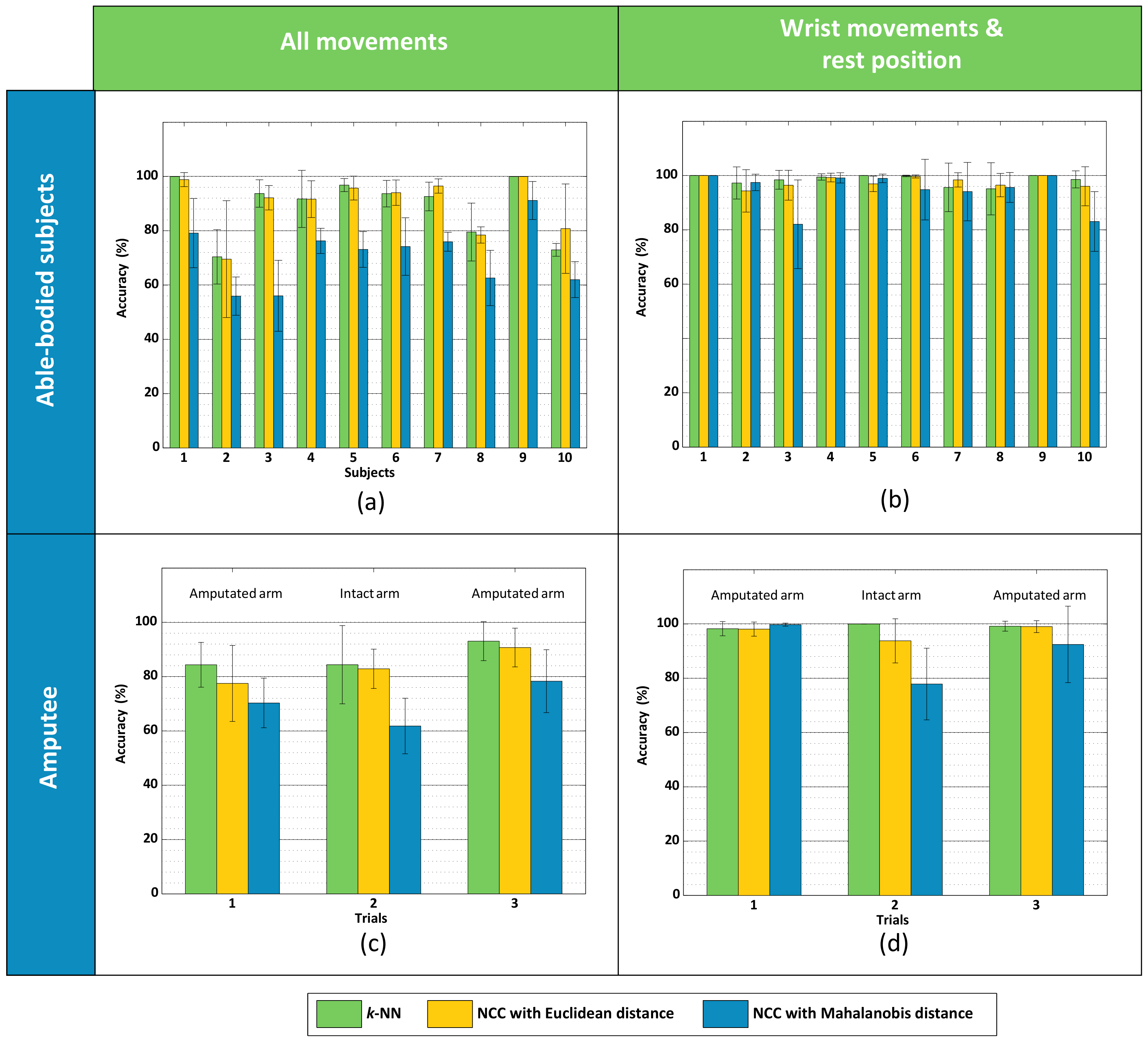
3. Results
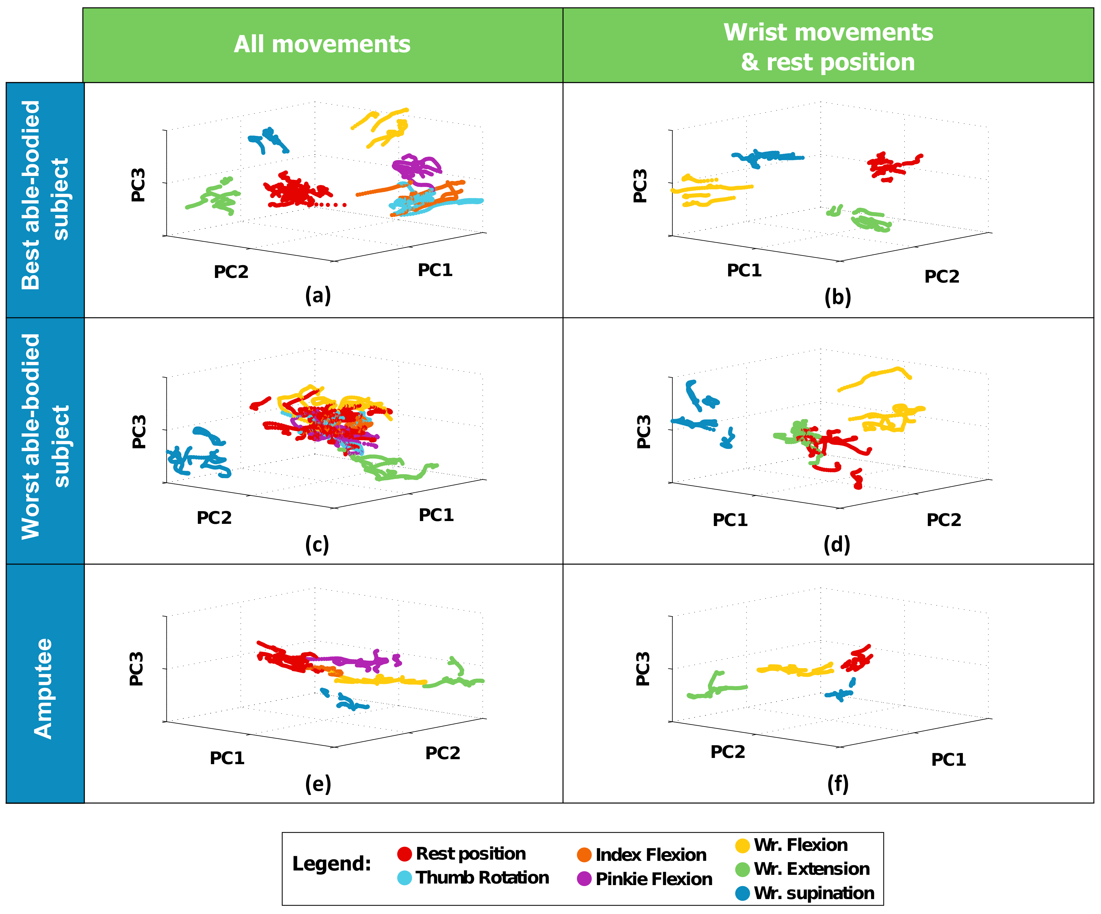
3.1. Experiment #1 (Able-Bodied Subjects)
3.2. Experiment #2 (Amputee)
4. Discussion
4.1. Tactile Myography for Myocontrol
4.2. What This Study Shows
4.3. Final Remarks and Future Work
Acknowledgments
Author Contributions
Conflicts of Interest
References
- Biddiss, E.; Chau, T. Upper-limb prosthetics: Critical factors in device abandonment. Am. J. Phys. Med. Rehabil. 2007, 86, 977–987. [Google Scholar] [CrossRef] [PubMed]
- Peerdeman, B.; Boere, D.; Witteveen, H.; in ’t Veld, R.H.; Hermens, H.; Stramigioli, S.; Rietman, H.; Veltink, P.; Misra, S. Myoelectric forearm prostheses: State of the art from a user-centered perspective. J. Rehabil. Res. Dev. 2011, 48, 719–738. [Google Scholar] [CrossRef] [PubMed]
- Engdahl, S.M.; Christie, B.P.; Kelly, B.; Davis, A.; Chestek, C.A.; Gates, D.H. Surveying the interest of individuals with upper limb loss in novel prosthetic control techniques. J. NeuroEng. Rehabil. 2015, 12, 1–11. [Google Scholar] [CrossRef] [PubMed]
- Micera, S.; Carpaneto, J.; Raspopovic, S. Control of hand prostheses using peripheral information. IEEE Rev. Biomed. Eng. 2010, 3, 48–68. [Google Scholar] [CrossRef] [PubMed]
- Maat, B.; Smit, G.; Plettenburg, D.; Breedveld, P. Passive prosthetic hands and tools: A literature review. Prosthet. Orthot. Int. 2018, 42, 66–74. [Google Scholar] [CrossRef] [PubMed]
- Schweitzer, W.; Thali, M.J.; Egger, D. Case-study of a user-driven prosthetic arm design: Bionic hand versus customized body-powered technology in a highly demanding work environment. J. NeuroEng. Rehabil. 2018, 15, 1. [Google Scholar] [CrossRef] [PubMed]
- Østlie, K.; Lesjø, I.M.; Franklin, R.J.; Garfelt, B.; Skjeldal, O.H.; Magnus, P. Prosthesis rejection in acquired major upper-limb amputees: A population-based survey. Disabil. Rehabil. Assist. Technol. 2012, 7, 294–303. [Google Scholar]
- Kyberd, P.J.; Hill, W. Survey of upper limb prosthesis users in Sweden, the United Kingdom and Canada. Prosthet. Orthot. Int. 2011, 35, 234–241. [Google Scholar] [CrossRef] [PubMed]
- i-LIMB Quantum. Available online: www.touchbionics.com/products/active-prostheses/i-limb-quantum (accessed on 22 March 2018).
- Fougner, A.; Stavdahl, Ø.; Kyberd, P.J.; Losier, Y.G.; Parker, P.A. Control of Upper Limb Prostheses: Terminology and Proportional Myoelectric Control - A Review. IEEE Trans. Neur. Syst. Rehab. Eng. 2012, 20, 663–677. [Google Scholar] [CrossRef] [PubMed] [Green Version]
- Jiang, N.; Dosen, S.; Müller, K.R.; Farina, D. Myoelectric control of artificial limbs: Is there the need for a change of focus? IEEE Signal Process. Mag. 2012, 29, 149–152. [Google Scholar] [CrossRef]
- Castellini, C.; Artemiadis, P.; Wininger, M.; Ajoudani, A.; Alimusaj, M.; Bicchi, A.; Caputo, B.; Craelius, W.; Dosen, S.; Englehart, K.; et al. Proceedings of the first workshop on Peripheral Machine Interfaces: Going beyond traditional surface electromyography. Front. Neurorobot. 2014, 8, 22. [Google Scholar] [CrossRef] [PubMed]
- Curcie, D.J.; Flint, J.A.; Craelius, W. Biomimetic finger control by filtering of distributed forelimb pressures. IEEE Trans. Neural Syst. Rehabil. Eng. 2001, 9, 69–75. [Google Scholar] [CrossRef] [PubMed]
- Schürmann, C.; Kõiva, R.; Haschke, R.; Ritter, H. A modular high-speed tactile sensor for human manipulation research. In Proceedings of the IEEE World Haptics Conference (WHC), Istanbul, Turkey, 21–24 June 2011; pp. 339–344. [Google Scholar]
- Ravindra, V.; Castellini, C. A comparative analysis of three non-invasive human-machine interfaces for the disabled. Front. Neurorobot. 2014, 8, 24. [Google Scholar] [CrossRef] [PubMed] [Green Version]
- Guo, J.Y.; Zheng, Y.P.; Kenney, L.P.J.; Bowen, A.; Howard, D.; Canderle, J.J. A comparative evalaution of sonomyography, electromyography, force, and wrist angle in a discrete tracking task. Ultrasound Med. Biol. 2011, 37, 884–891. [Google Scholar] [CrossRef] [PubMed]
- Lucaccini, L.F.; Kaiser, P.K.; Lyman, J. The French electric hand: Some observations and conclusions. Bull. Prosthet. Res. 1966, 10, 31–51. [Google Scholar]
- Phillips, S.L.; Craelius, W. Residual Kinetic Imaging: A Versatile Interface for Prosthetic Control. Robotica 2005, 23, 277–282. [Google Scholar] [CrossRef]
- Wininger, M.; Kim, N.; Craelius, W. Pressure signature of forearm as predictor of grip force. J. Rehabil. Res. Dev. (JRRD) 2008, 45, 883–892. [Google Scholar] [CrossRef]
- Yungher, D.A.; Wininger, M.T.; Barr, J.; Craelius, W.; Threlkeld, A.J. Surface muscle pressure as a measure of active and passive behavior of muscles during gait. Med. Eng. Phys. 2011, 33, 464–471. [Google Scholar] [CrossRef] [PubMed]
- Yungher, D.; Craelius, W. Improving fine motor function after brain injury using gesture recognition biofeedback. Disabil. Rehabil. Assist. Technol. 2012, 7, 464–468. [Google Scholar] [CrossRef] [PubMed]
- Lukowicz, P.; Hanser, F.; Szubski, C.; Schobersberger, W. Detecting and Interpreting Muscle Activity with Wearable Force Sensors. In Pervasive Computing; Fishkin, K.P., Schiele, B., Nixon, P., Quigley, A., Eds.; Springer: Berlin/Heidelberg, Germany, 2006; Volume 3968, pp. 101–116. [Google Scholar]
- Connan, M.; Ruiz Ramírez, E.; Vodermayer, B.; Castellini, C. Assessment of a wearable force- and electromyography device and comparison of the related signals for myocontrol. Front. Neurorobot. 2016, 10. [Google Scholar] [CrossRef] [PubMed]
- Cho, E.; Chen, R.; Merhi, L.K.; Xiao, Z.; Pousett, B.; Menon, C. Force Myography to Control Robotic Upper Extremity Prostheses: A Feasibility Study. Front. Bioeng. Biotechnol. 2016, 4, 18. [Google Scholar] [CrossRef] [PubMed]
- Kõiva, R.; Riedenklau, E.; Viegas, C.; Castellini, C. Shape conformable high spatial resolution tactile bracelet for detecting hand and wrist activity. In Proceedings of the ICORR—International Conference on Rehabilitation Robotics, Singapore, 11–14 August 2015; pp. 157–162. [Google Scholar]
- Radmand, A.; Scheme, E.; Englehart, K. High-density force myography: A possible alternative for upper-limb prosthetic control. J. Rehabil. Res. Dev. 2016, 53, 443–456. [Google Scholar] [CrossRef] [PubMed]
- Lowe, D.G. Object Recognition from Local Scale-Invariant Features. In Proceedings of the International Conference on Computer Vision, Corfu, Greece, 20–25 September 1999. [Google Scholar]
- Luo, S.; Mou, W.; Althoefer, K.; Liu, H. Novel Tactile-SIFT Descriptor for Object Shape Recognition. IEEE Sens. 2015, 15, 5001–5009. [Google Scholar] [CrossRef]
- Castellini, C.; Passig, G.; Zarka, E. Using ultrasound images of the forearm to predict finger positions. IEEE Trans. Neural Syst. Rehabil. Eng. 2012, 20, 788–797. [Google Scholar] [CrossRef] [PubMed] [Green Version]
- Sierra González, D.; Castellini, C. A realistic implementation of ultrasound imaging as a human-machine interface for upper-limb amputees. Front. Neurorobot. 2013, 7, 17. [Google Scholar] [CrossRef] [PubMed] [Green Version]
- Ortenzi, V.; Tarantino, S.; Castellini, C.; Cipriani, C. Ultrasound Imaging for Hand Prosthesis Control: A Comparative Study of Features and Classification Methods. In Proceedings of the ICORR—International Conference on Rehabilitation Robotics, Singapore, 11–14 August 2015; pp. 1–6. [Google Scholar]
- Krizhevsky, A.; Sutskever, I.; Hinton, G.E. ImageNet Classification with Deep Convolutional Neural Networks. In Proceedings of the 25th International Conference on Neural Information Processing Systems, Lake Tahoe, NV, USA, 3–6 December 2012; Pereira, F., Burges, C.J.C., Bottou, L., Weinberger, K.Q., Eds.; pp. 1097–1105. [Google Scholar]
- Jones, N. The learning machines. Nature 2014, 505, 146–148. [Google Scholar] [CrossRef] [PubMed]
- Weiss, K.; Wörn, H. The working principle of resistive tactile sensor cells. In Proceedings of the IEEE International Conference Mechatronics and Automation (ICMA), Niagara Falls, ON, Canada, 29 July–1 August 2005; Volume 1, pp. 471–476. [Google Scholar]
- Wolfgang Warmbier GmbH & Co. KG. Available online: www.warmbier.com (accessed on 22 March 2018).
- Polyform Kunststofftechnik GmbH & Co. Betriebs KG. Available online: www.polyform.de (accessed on 22 March 2018).
- Strazzulla, I.; Nowak, M.; Controzzi, M.; Cipriani, C.; Castellini, C. Online Bimanual Manipulation Using Surface Electromyography and Incremental Learning. IEEE Trans. Neural Syst. Rehabil. Eng. 2016, in press. [Google Scholar] [CrossRef] [PubMed]
- Harris, C.; Stephens, M. A combined corner and edge detector. In Proceedings of the 4th Alvey Vision Conference, Manchester, UK, 31 August–2 September 1988; Volume 15, p. 50. [Google Scholar]
- Boschmann, A.; Platzner, M. A Computer Vision-Based Approach to High Density EMG Pattern Recognition Using Structural Similarity; University of New Brunswick’s Myoelectric Controls/Powered Prosthetics Symposium (MEC): Fredericton, NB, Canada, 2014. [Google Scholar]
- Castellini, C.; Passig, G. Ultrasound image features of the wrist are linearly related to finger positions. In Proceedings of the IROS—International Conference on Intelligent Robots and Systems, San Francisco, CA, USA, 25–30 September 2011; pp. 2108–2114. [Google Scholar]
- De Oliveira Viegas, C.L. Tactile-Based Control of a Dexterous Hand Prosthesis. Master’s thesis, Friedrich-Alexander-Universität Erlangen-Nürnberg, Erlangen, Germany, 2016. [Google Scholar]
- Powell, M.A.; Thakor, N.V. A Training Strategy for Learning Pattern Recognition Control for Myoelectric Prostheses. J. Prosthet. Orthot. 2013, 25, 30–41. [Google Scholar] [CrossRef] [PubMed]
- Jaquier, N.; Connan, M.; Castellini, C.; Calinon, S. Combining electro- and tactile myography to improve hand and wrist activity detection in prostheses. MDPI Technol. 2017, 5, 64. [Google Scholar]
- Fang, Y.; Hettiarachchi, N.; Zhou, D.; Liu, H. Multi-Modal Sensing Techniques for Interfacing Hand Prostheses: A Review. IEEE Sen. J. 2015, 15, 6065–6076. [Google Scholar] [CrossRef]
- Jiang, N.; Vujaklija, I.; Rehbaum, H.; Graimann, B.; Farina, D. Is Accurate Mapping of EMG Signals on Kinematics Needed for Precise Online Myoelectric Control? IEEE Trans. Neural Syst. Rehabil. Eng. 2014, 22, 549–558. [Google Scholar] [CrossRef] [PubMed]
- Castellini, C.; Bongers, R.M.; Nowak, M.; van der Sluis, C.K. Upper-limb prosthetic myocontrol: Two recommendations. Front. Neurosci. 2015, 9, 496. [Google Scholar] [CrossRef] [PubMed] [Green Version]


© 2018 by the authors. Licensee MDPI, Basel, Switzerland. This article is an open access article distributed under the terms and conditions of the Creative Commons Attribution (CC BY) license (http://creativecommons.org/licenses/by/4.0/).
Share and Cite
Castellini, C.; Kõiva, R.; Pasluosta, C.; Viegas, C.; Eskofier, B.M. Tactile Myography: An Off-Line Assessment of Able-Bodied Subjects and One Upper-Limb Amputee. Technologies 2018, 6, 38. https://doi.org/10.3390/technologies6020038
Castellini C, Kõiva R, Pasluosta C, Viegas C, Eskofier BM. Tactile Myography: An Off-Line Assessment of Able-Bodied Subjects and One Upper-Limb Amputee. Technologies. 2018; 6(2):38. https://doi.org/10.3390/technologies6020038
Chicago/Turabian StyleCastellini, Claudio, Risto Kõiva, Cristian Pasluosta, Carla Viegas, and Björn M. Eskofier. 2018. "Tactile Myography: An Off-Line Assessment of Able-Bodied Subjects and One Upper-Limb Amputee" Technologies 6, no. 2: 38. https://doi.org/10.3390/technologies6020038
APA StyleCastellini, C., Kõiva, R., Pasluosta, C., Viegas, C., & Eskofier, B. M. (2018). Tactile Myography: An Off-Line Assessment of Able-Bodied Subjects and One Upper-Limb Amputee. Technologies, 6(2), 38. https://doi.org/10.3390/technologies6020038