1. Introduction
The most investigated chipless tag solutions are based on the frequency domain detection using the tag’s specific spectral signature. These RFID tags are composed of arrays of small printed scatterers (coding particles). The principle of encoded information can be described as either presence or non-presence on each scatterer’s peak in the tag’s spectral signature, which represents logical one or zero, respectively [
1]. These tags have been intensively investigated recently [
1,
2,
3,
4,
5,
6,
7]. The aim is to find a microwave frequency equivalent of optical barcodes systems. The designed microwave tags must be, therefore, optimized with the aim to reduce the taken area. Reducing the distance between particular resonators, however, increases mutual coupling between them. Mutual coupling detunes the response of neighboring resonators in the tag. Due to this, the logical “zeros” that are coded by the absence of the corresponding resonance is difficult to detect since the neighboring resonances are detuned from their original position. This reduces and possibly prevents the reliability of reading the coded information. We have proposed two ways for reducing the mutual coupling. This includes increasing the distance between resonators by tapering their arms [
8] and rearranging positions of resonators in the tag [
9]. In this scenario, the resonators with neighboring resonant frequencies are located at a higher distance, which means their coupling is reduced.
Professional electromagnetic (EM) simulators usually require substantial time to perform full-wave analysis of resonator arrays and to calculate the radar cross section (RCS) or any equivalent quantity as a reflection coefficient in the plane of the RFID transponder. Equivalent electric circuits represent an effective tool for simplified and fast analysis of various microwave structures [
10]. They reflect physical behavior of the structure and can accelerate preliminary analysis of originally very complex structures while sufficient or acceptable accuracy is maintained.
This paper employs a simple equivalent circuit model (ECM) (originally proposed in [
11]) of the RFID tag composed of an array of U-folded dipoles [
8,
9] to predict and study its RCS response. RCS at each frequency is related to currents flowing in individual coupled resonant circuits representing original tag scatterers. These currents correspond to the magnetic field of the reflected wave. The approach itself is subsequently applied toward understanding the influence of inter-element mutual coupling on the amplitude level and frequency stability of resonant peaks of predicted RCS response. This is crucial for proper identification of coded information by a chipless tag.
The paper further compares predicted and measured RCS response of the tag composed of U-folded dipoles presented in Reference [
1] with recently proposed tapered U-folded dipoles [
8] and with the tag composed of resonators rearranged in their positions [
9]. Based on that evidence, the advantage of the tags with reduced mutual coupling between neighboring resonators is shown.
Therefore, the proposed simplified analysis might serve to pre-evaluate the suitability of particularly shaped scatterers that are intended to be used to implement chipless RFID tags. Results obtained by the equivalent circuit modeling and measurement exhibit satisfactory agreement.
3. Equivalent Circuit Model of Resonator Array
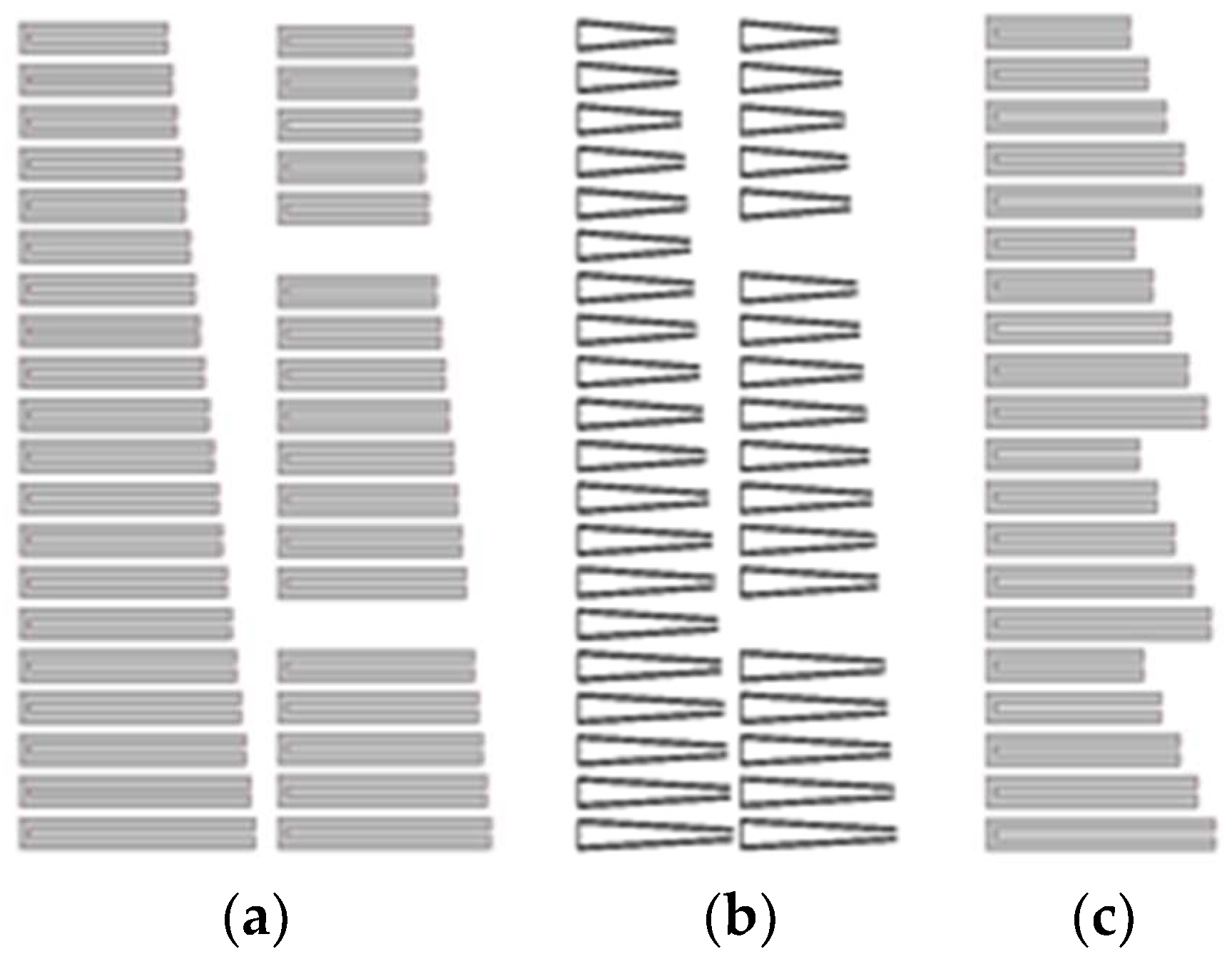
Figure 2b shows the layout of the uni-planar RFID chipless tag composed of an array of 20 T-UDs presented in Reference [
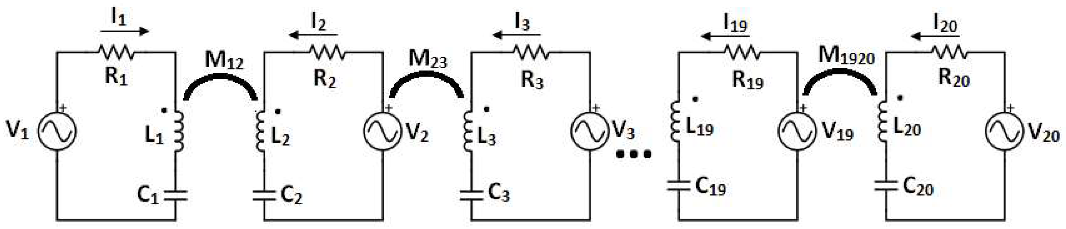
8]. The equivalent circuit of the
ith single resonator is composed of a series resonant circuit
Li,
Ci, and
Ri (see
Figure 3) [
11]. This circuit is fed by the source of voltage
Vi that corresponds to the incident electric field
E irradiating the tag.
where
lieff is the effective length of the
ith resonator working as a receiving antenna. Changing amplitudes and phases of
Vi, we can simulate oblique incidence of the wave or its different forms-planar, cylindrical, and spherical. The presented analysis is done for the perpendicular incidence of the plane wave so all voltages are taken
Vi = 1 and are in-phase. The magnetic field of the reflected wave excited by dipoles corresponds linearly to the current flow along these dipoles [
12]. Predicted RCS is, therefore, proportional to the power of the sum of currents and, in particular, resonators of the equivalent circuit [
13].
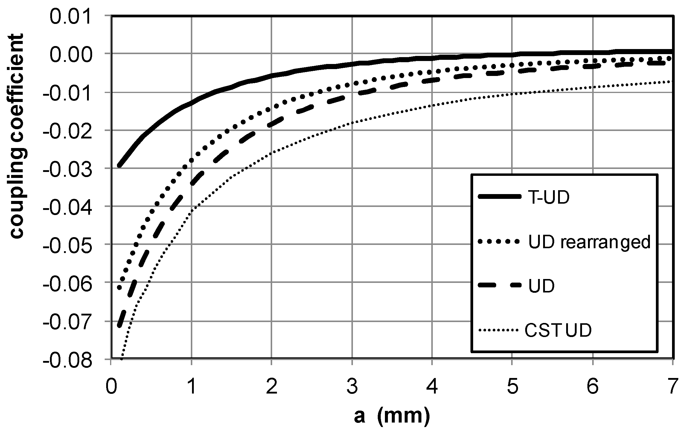
The particular resonant circuits are coupled by a magnetic field and this coupling is represented by mutual inductances. The coupling coefficient decreases with increasing distances, which is shown in
Figure 4. Consequently, it is sufficient to consider only coupling of the neighboring resonators. This has been proven by analyzing the circuit from
Figure 3 by adding mutual inductances between the second neighbors.
The missing resonator in the tag codes bit with logical ‘0’ is represented by a circuit with resistance
Ri = 1 MΩ that assures nearly a zero value of the passing current and consequently no (or negligible) contribution to the response (2). Equations for each loop in the circuit from
Figure 3 are shown below.
where
XLi = jω
Li,
XMij = jω
Mij, and
XCi = 1/(jω
Ci). Solution of (3) determines the particular currents and the tag RCS response (2).
4. Calculation of Dipole Inductances and Mutual Inductances
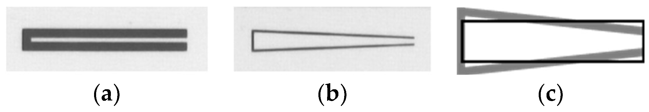
The folded dipoles shown in
Figure 1a,b can be viewed as current loops and their inductance and mutual inductance of a pair of the loops can be calculated by using Neumann’s formula from Reference [
12].
In Equation (4),
and
are elements of the loops and
is the oriented distance between these elements. To simplify the calculation, the original folded dipole is substituted by the current loop located at the inner edges of strips. The tapered U-folded dipole is substituted by the rectangular current loop, which is drawn in
Figure 1c. The distribution of current passing along the dipoles arms described by the sine function is approximated by an average value equal to 2/π.
The coupling coefficient that describes the mutual inductance between the pair of elements with inductances
L1 and
L2 and mutual inductance
M is defined by the equation below.
The coupling coefficient of adjacent pairs of UDs, T-UDs, and rearranged UDs, 25 mm, and 25.5 mm in length, located at distance
a, is plotted in
Figure 4. The mutual coupling of T-UDs is significantly weaker than the coupling between UDs. This documents the basic advantage of the proposed tapered U-folded dipoles. Another way to reduce the mutual inter element coupling is to use the array with rearranged resonator positions [
9]. The effect of the reduced coupling coefficient is not apparent here (
Figure 4).
Figure 4 further shows the line marked CST UD, which represents the transmission between two UDs calculated by the CST Microwave Studio. The two resonators are fed by point ports connected to the open end. This verifies the behavior described above.
5. Analysis Results
The results of the equivalent circuit analysis (RCS) are normalized. This occurs when values of all exciting voltages are equal to 1 V. The other source of inexact results follows from a rough estimate of RCS calculated by Equation (2).
The equivalent circuit analysis was applied to evaluate performance of up to 20-element arrays of proposed T-UD sequentially detuned by changing their length by 0.5 mm from 16 mm to 25.5 mm so that the outer size of the array is 69 × 25.5 mm
2 (see
Figure 2b). RCS of fabricated tags was measured by a one-port vector measurement of monostatic RCS in a free space [
8]. The obtained results were verified by simulations performed using the Zeland IE3D software (Mentor Graphics, Wilsonville, OR, USA).
The circuit parameters in the equivalent circuit were determined by calculating data for
Figure 4. Capacitances were calculated from resonant frequencies of particular resonators and their inductances. Resistor values were evaluated using the skin effect [
12].
where
li is total length of the strip
w in width,
σ is conductivity, and
δ is the penetration depth.
The first analyzed structure is one from
Figure 2a. There is no measure taken here to reduce the coupling.
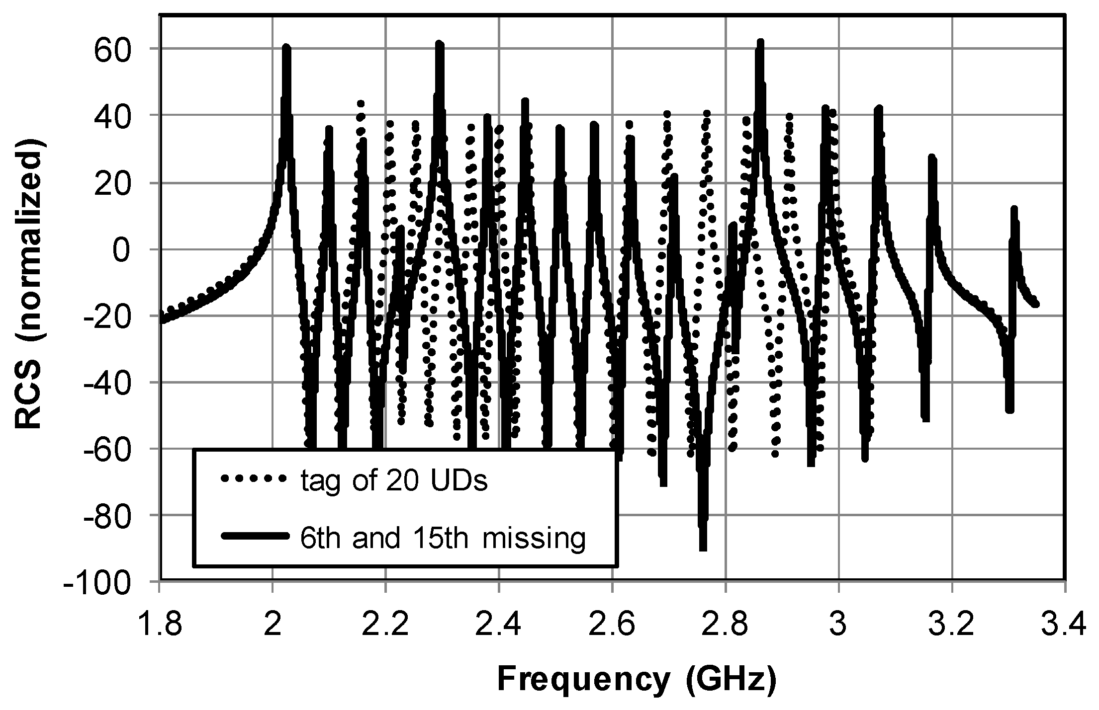
Figure 5 shows the response of the tag composed of 18-element and 20-element UDs from
Figure 1a. The resonators are coupled relatively strongly. The exceptions are the first and last resonators. They have neighbors from only one side so RCS at maximum of the first resonator response is higher than in the case of others. RCS at maximum of the last resonator is lower. The solid line shows a response of the tag with particular UD resonators removed to code logical zero bit information. Peaks adjacent to missing resonances are strongly distorted both in the amplitude level and the frequency position. Strong element coupling, therefore, makes the coded information difficult to read properly and predicts that such elements are not suitable for implementing in chipless RFID tags.
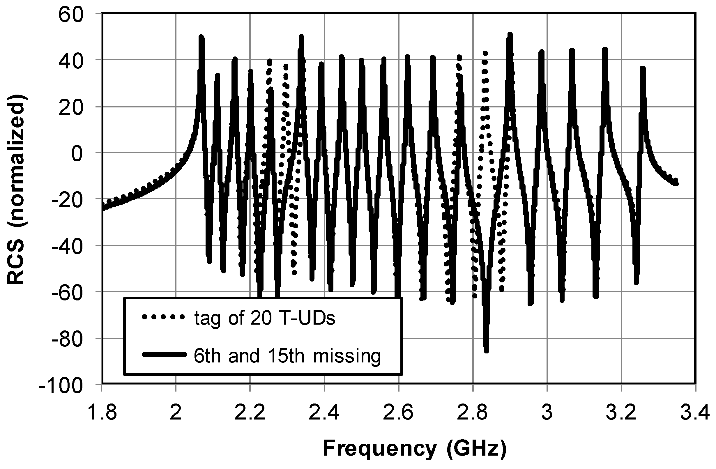
Yet, weak mutual coupling in the case of an array of recently proposed T-UD resonators of
Figure 1b presented in Reference [
8] assures a stable amplitude level and frequency positions of adjacent resonant peaks. Consequently, it enables their reliable identification in comparison with the RCS response of the full 20-bit tag (see
Figure 6).
Table 1 lists parameters of the equivalent circuit used to analyze the tag from
Figure 2b.
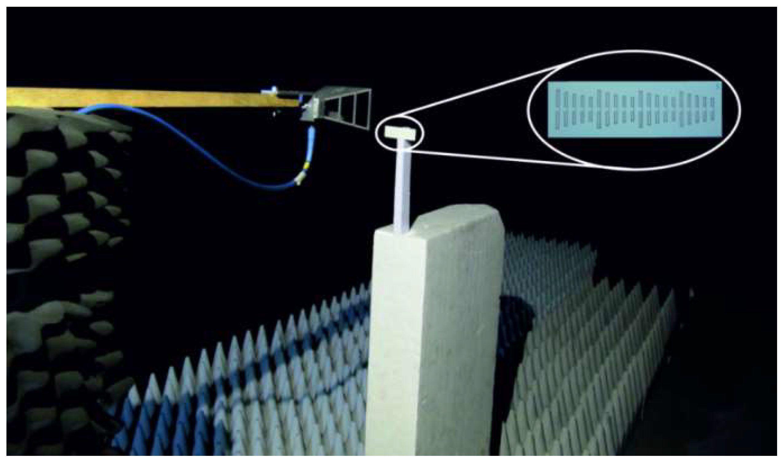
Verification of the simulated results was performed by the monostatic measurement of tags RCS performance by an R & S ZVA 40 network analyzer in frequency band 2 to 4 GHz in an anechoic chamber (see
Figure 7). It was based on the reflection coefficient evaluation of the double ridge horn antenna DRH 20 [
14] in front of which a scatterer at a distance of 150 mm was placed. The tag’s RCS response was calculated with the help of the relation used in Reference [
1] and modified so that it was applicable to the one-port case described in Reference [
9].
where
is the reflection coefficient when the measured tag is used as a scatterer.
represents the reflection coefficient when the reference plate is used as a scatterer.
is the reflection coefficient of the antenna in case no scatterer is used and comprises the residual reflection from the experimental surroundings.
is the RCS of the measured tag and
is the RCS of the reference scatterer, which is the rectangular metal plate 25 × 70 mm
2 in size (corresponding with the measured tags) and 0.3 mm in thickness. Its analytical formula for RCS is shown below.
The monostatic measurement arrangement enables the avoidance of the use of angular dependent formula for reference scatterer and eliminates the influence of mutual coupling of the transmitting and receiving antennas in case of bi-static measurement.
The measurement received that power
PR can be determined using the well-known radar equation [
15].
where
r is a distance between the antenna and the tag with RCS equal to
σtag and VNA transmitted power
PT equals 10 dBm and gain of the transmitted/received antenna
G is 8 dBi. The received power for a measurement distance
r = 150 mm is calculated as approximately −52 dBm for the frequency band center, which is valuable with a sufficient reserve in comparison with the noise threshold of the VNA or another receiving device. However, a relatively low measurement distance
r was used because the guarantee is significantly higher than the reflection from the measured tag in comparison with a number of residual reflections from experimental surroundings. Consequently, clear RCS response can be evaluated from this measurement, according to Reference [
7].
In spite of the expected smaller range, this solution can be suitable for certain chipless RFID applications operated on a short distance, e.g., identification of small objects on a transport belt, etc.
The results of the equivalent circuit analysis plotted in
Figure 6 can be well compared with experimental data presented in Reference [
8].
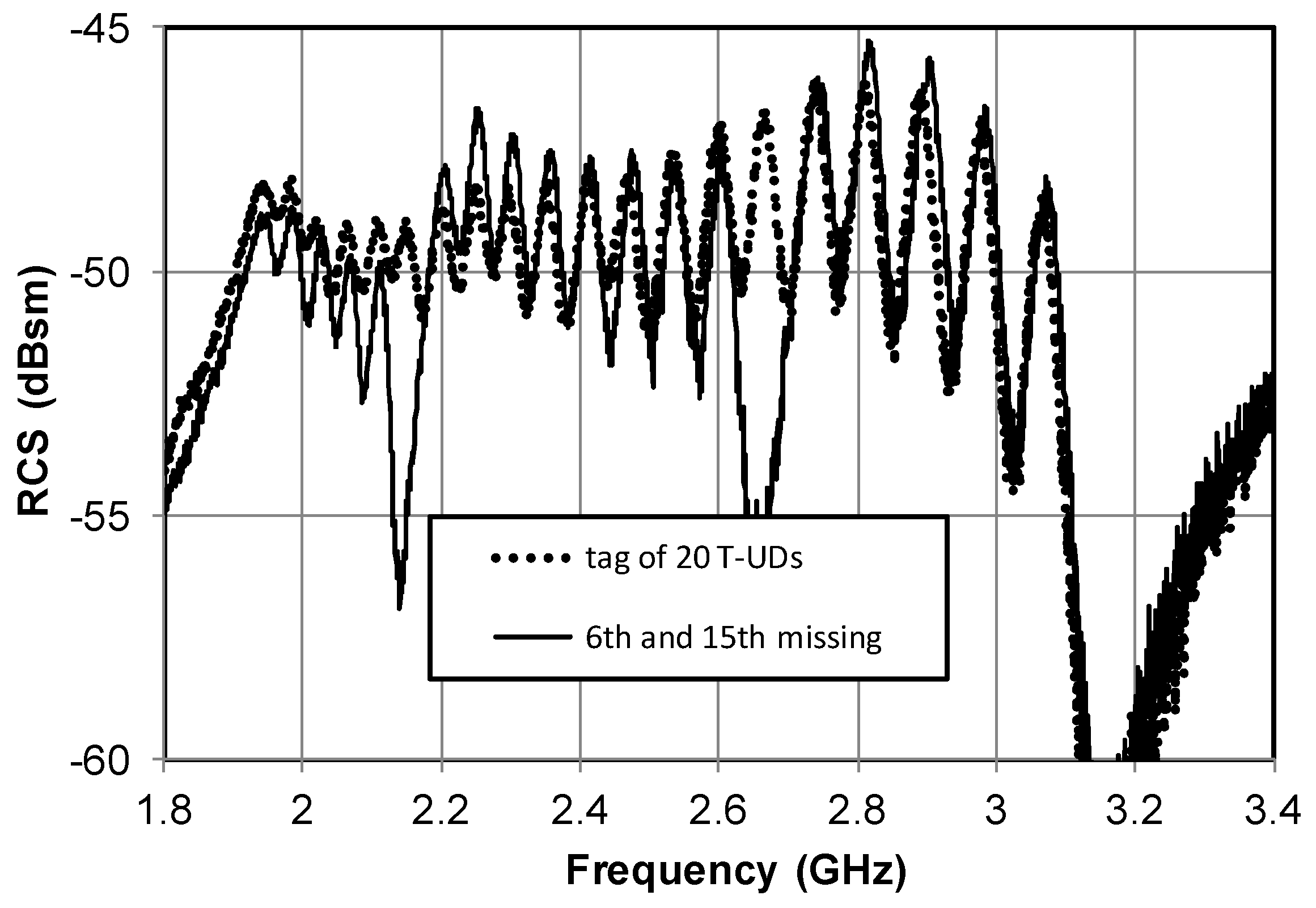
Figure 8 shows measured RCS response of the T-UD tags composed of 20 and 18 resonators. What cannot be exactly compared is the level of the RCS response. The RCS calculated from the equivalent circuit represents only some normalized values since all voltages are taken equal to 1 regardless of dipole effective lengths and RCS values are substituted by the sum of currents (2). Predicted RCS shown in
Figure 6 and measured in
Figure 8 proves the suitability of the structure, i.e., recognition of individual resonances from
Figure 2b to design the RFID tag.
The coupling coefficient between two T-UD resonators (
Figure 2b) at their distance equal to 1 mm is −0.013. This is a sufficiently low value that assures reliable reading of the coded information (see
Figure 6 and
Figure 8). To get the same behavior of the tag composed of UDs (
Figure 2a), the distance between resonators must be increased to 2.7 mm. Therefore, the size of the chip would be significantly increased.
Another way to reduce the mutual coupling in arrays of planar resonators was proposed in Reference [
9]. The positions of resonators in the array are rearranged according
Figure 2c.
Figure 9 plots RCS of this tag calculated with the help of the equivalent circuit. It is possible to distinguish reliably the missing resonances of the missing resonant elements. The amplitudes and frequency positions of adjacent resonant peaks are not affected. The plot documents the suitability of that simple solution to predict the tag behaviors documented by measured RCS plotted in
Figure 10.
Measurement results of both tags with reduced mutual coupling can be compared with the measured RCS response of the original tag without any measure taken to reduce the coupling plotted in
Figure 11. The calculated response of this tag is plotted in
Figure 5.


