
Numerical Simulation of Single Droplet Impingement upon Dynamic Liquid Film Obliquely

1
Three Gorges Mathematical Research Center, China Three Gorges University, Yichang 443002, China
2
College of Science, China Three Gorges University, Yichang 443002, China
3
Science and Technology on Electromagnetic Scattering Laboratory, Beijing Institute of Environmental Features, Beijing 100854, China
*
Author to whom correspondence should be addressed.
Mathematics 2022, 10(17), 3193; https://doi.org/10.3390/math10173193
Submission received: 4 August 2022
/
Revised: 23 August 2022
/
Accepted: 31 August 2022
/
Published: 4 September 2022
(This article belongs to the Special Issue Numerical Methods for Computational Fluid Dynamics)
Abstract
:To better understand the application of droplet impingement in industry and agriculture, in this paper, the coupled level set and volume of fluid () method is applied to study droplet oblique impact on a dynamic liquid film. The conclusions are the following: the downstream crown height increases and then decreases as the impact angle increases, whereas upstream crown height and spreading length decrease significantly; moreover, the spreading length and upstream crown height increase with the increase of film velocity, while the downstream crown height decreases instead. The increase of gas density inhibits both upstream and downstream crowns. When the fluid viscosity decreases or the impact velocity increases, the crown height increases significantly, which easily leads to crown rupture or droplet splash. The increase in impact velocity leads to an increase in spreading length; however, viscosity has almost no effect on the spreading length.
1. Introduction
Droplet–surface interaction is widely involved in fluid dynamics, such as multi-phase flow and interfacial flow. It plays an important role in industrial applications as well, including paint spraying, fire extinguishing, spray cooling, and fuel injection in internal combustion engines [1,2,3]. However, most of the impact processes usually involve droplets colliding with a dry surface, and subsequently the surface will be covered by a moving fluid, which eventually evolves into the impact of droplets on a moving liquid film. Moreover, during the impingement, it is not always vertical, but collides with an angle; therefore, droplet impinging obliquely on a moving liquid film is worthy of extensive attention and investigation.
Extensive experiments and numerical simulations have shown that a normal impact on a static liquid film is accompanied by distinct symmetrical characteristics, and the results revealed crown splash and deposition phenomena [4,5,6,7,8,9,10,11]. When a droplet impacts at an inclined angle, a distinct asymmetric feature can be produced [12,13,14,15,16,17]. Whereas droplet impingement on dynamic liquid films normally, many complex interface structures can be observed, such as bouncing, partial agglomeration, complete agglomeration, scattered holes, base crown separation, etc. [18,19,20]. To further analyze the flow characteristics, Gao and Li [21] investigated the influence of a single droplet on a flowing liquid film by experiment and theory, a threshold value for the splash phenomenon on dynamic film was derived. Ming and Jing [22] used a lattice Boltzmann method () for analytical studies of droplets striking a moving wall covered with liquid film. It was found that the moving wall played a role in enhancing or inhibiting splashing. Zhao et al. [23] found that the spreading velocity of a droplet on a moving liquid film is half the sum of the upstream and downstream spreading velocities by numerical and theoretical studies. Okawa et al. [12] experimentally studied single droplet impingement obliquely. The results revealed obvious asymmetric features, and no satellite droplets were observed when the impact angle was greater than .
There are many studies on the effect of parameters in the droplet impact dynamic liquid film or oblique impingement [13,14,15,16,24,25]. For example: Raman et al. studied the effect of parameters, including droplets gap, viscosity and gas density on the crown structure and jet flow [24]. Liu et al. [13] employed a to investigate the impingement on a stationary film with horizontal velocity. It was indicated that when increasing the Weber number (), the crown height on the front side of the droplet was higher, but decreased on the backside. Guo et al. [15] employed a method to simulate a drop obliquely impacting upon a stationary film. Outcomes demonstrated that the radius of the rear side of the advancing droplet decreases with an increasing impact angle, while the crown radius of the front side increases.
On the one hand, although there are many numerical studies on crown evolution and splash phenomena, most of these studies are for individual dynamic films or oblique impingement. On the other hand, the physical parameters considered in studies on oblique impacts are not particularly adequate. Therefore, in this paper, the method is used to study the single droplet oblique impact on a dynamic liquid film. It also focuses on the effects of tilted impact dynamic liquid film on the crown structure and spreading length under various influencing parameters (impact angle and velocity, liquid film flow rate, gas–liquid density ratio and fluid viscosity), and analyzes the related mechanism.
The structure of our work is organized as follows. In Section 1, the physical model and the numerical method are introduced. In Section 3, three cases are implemented to verify the reliability of the model. The factors including impact angle, film speed, density ratio, fluid viscosity and impact velocity are discussed in Section 4 during the impingement. The summary and conclusions are given in the last section of this paper.
Physical Model
Figure 1 shows a sketch, in which a single droplet collides with a dynamic liquid film at a certain angle, where the circular droplet diameter is , is the impact angle, g indicates acceleration of gravity; and and are the liquid film velocity and film thickness, respectively. We consider a two-dimensional physical model, given that the upper boundary condition is the pressure outlet, the lower boundary condition is the no-slip boundary condition, and the left and right sides are the velocity inlet and pressure outlet boundary conditions, respectively. The static contact angle of the wall is set as .
2. Physical Model and Mathematical Model
To further simplify the physical model, there are three assumptions that need to be considered. (I) Droplet and film have the same physical properties and both are incompressible Newtonian fluids. (II) At the initial moment, droplet is tangential to the film. (III) The impact process is considered a laminar flow.
Mathematical Model
To obtain the two-phase interface, a typical VOF model has been put forward by Hirt and Nichols [26], and the volume fraction function can be written as:
U and t are the velocity and time, respectively. The means the ratio of the volume of liquid in a mesh to the volume of the grid, and can be divided into the following three cases:
The extra third term is an artificial compression term introduced to sharpen the interface. is the gas–liquid relative velocity, compressing the interface to improve its resolution. Moreover, is expressed as follows [27,28]:
is controlled by the , which limits the artificial compression velocity. If there is no compression, then , whilst if , there is conservative compression, and when , it means there is high compression.
To capture the two-phase interface, the LS method was proposed by Osher and Sethian [29], and the function is expressed as:
The LS field is derived from via , where is a small non-dimensional number [27], and is the cell size. In addition, the density and dynamic viscosity can be obtained by the smooth Heaviside function :
where the subscripts l and g are liquid and gas, respectively. The is expressed as:
The governing equations for the gas–liquid incompressible flow are expressed below.
where and are the surface tension coefficient and curvature, respectively. The is a constant of , and is defined as below.
When the droplet interacts with the liquid film, the interface may become blurred or oscillate; therefore, it is necessary to reconstruct the interface at each time step. In the reconstruction, the values of VOF and LS functions are used. The volume fraction of the liquid phase in the VOF model provides the interface value, and the normal vector n calculated by the LS function determines the direction of the interface. The concept of piecewise Linear interface computation (PLIC) is used to construct the interface [10].
In this paper, the governing equations are discretized by the finite volume method (FVM). The pressure-implicit with splitting of operators (PISO)-semi-implicit method for pressure linked equations (PIMPLE) algorithm [30] is employed to solve for the pressure–velocity coupling. The Crank-Nicolson scheme is utilized for the temporal terms; and a total variation diminishing (TVD) scheme is applied to the spatial discretization. The maximum Courant number (Co) is given as 0.3 and to control the time step, where .
3. Model Validation
For the two-dimensional physical model, the mesh independence has been verified in our previous study [31]; and the number of grids for each case is given as .
To illustrate the reliability of the present model, we compared three experiments. Figure 2 displays the outcome of experimental [12] and numerical simulations comparing a single droplet impacting a liquid film obliquely. The given parameters include droplet diameter mm, impact speed m/s, film thickness mm, and impact angle . By comparing with the simulation results in the Ref. [32], our results clearly capture the splash of droplets.
Figure 3 reveals the results of experimental [21] and numerical simulations of drops vertically colliding with a dynamic liquid film. The relevant parameters for the experiment are given as mm and m/s, and film thickness and velocity are mm and m/s, respectively. The equivalent conditions are employed in our numerical simulations. From the simulation outcomes, the morphology of the crown and formation of satellite droplets can be clearly captured, which is very consistent with the experimental results.
To further validate our model, we carried out a quantitative comparison with experimental results from Ref. [33]. Figure 4a,b plotted the impact behavior of the experiment and numerical, respectively, as a function of and impact angle . The solid line and dashed line are plotted by the equation , where and . We note that the solid line (+) and dashed line (−) are the threshold from deposition (marked in blue) to single-sided splashing, and single-sided splashing (marked in black) to omni-directional splashing (marked in red). The simulation results of the above three cases basically match with the experimental results, thus verifying the current feasibility of our model.
4. Results and Discussion
In this section, the height of the upstream and downstream crowns of the droplet, the spreading length and the morphological structure of the crowns are discussed in detail. The effects of different impact angles, dynamic film velocity, density ratio, fluid viscosity and impact speed are considered. The baseline parameters selected for the simulations are: mm, mm, m/s, m/s, , and , where the defines . The values are varied when the effects of specific parameters are discussed, while the other parameters maintain their corresponding baseline values. The parameters for the validation of the model, as well as the parameters for the subsequent arithmetic examples, are shown in Table 1.
4.1. Effect of Droplet Impact Angle
For a special situation, when , the asymmetry can be observed under the action of the dynamic film speed as the previous study [21,25]. We now focus on the effect of droplet colliding with dynamic films obliquely. The structure of the interface is investigated by six different impact angles (, , , , and ).
Figure 5 shows the results of the interfacial evolution diagram for a single droplet impacting a dynamic liquid film at the above angles. When the droplet impinges on the dynamic film at an inclination, with the increase of , the asymmetric flow characteristics become more obvious; simultaneously, crowns of different heights appear upstream and downstream, respectively. As the impingement continues, the heights of the crowns on both sides gradually increase and extend outside. When the initial impact angle is no more than , the splashing satellite droplets can be observed upstream, and similar interface morphology can be obtained. When the inclination angle is between and , no splashing can be observed; when leads to , splashing can be found in the downstream; and when , the upstream crown becomes shorter, while the downstream crown is not formed and there is no satellite droplet splashing. In addition, the angle between the upstream crown and the dynamic film increased significantly with the increase of the impact angle, and when the impact angle reaches , the upstream crown was almost perpendicular to the dynamic film. When the impact angle increases further, the velocity component in the vertical direction decreases, while the velocity component in the horizontal direction increases, which leads to a decrease in the fluid entering the left crown and an increase in the mass of fluid entering the right crown. Therefore, increasing the impact angle makes the upstream crown more stable for the purpose of suppressing droplet splashing, while the downstream becomes unstable and prone to splashing.
Figure 6 gives the pressure distribution field for an impact angle of . It is not difficult to find that when ms, the pressure is unevenly distributed inside the impact area, gradually increasing from top to bottom. As the impingement continues, the maximum pressure value starts to decrease slowly, and the pressure near the upstream impact point is much higher than the pressure in other regions, while at ms, the pressure value inside the impact region is almost equal to the pressure value outside. Yet, on the rim of the crown on both sides exists a larger pressure. The phenomenon agrees with the simulation results in the reference [34] well.
The relationship between the left crown height (), right crown height () and time at different angles are given in Figure 7. For the left crown, we find that as the impact angle increase, the height of the left side crown decreases instead. In addition, a local decrease in the upstream crown height has appeared when the impact angle is and . This is due to the fact that the crown is unstable, and it is affected by the Rayleigh–Plateau instability, which forms secondary droplets, and the fluid at the end of the crown leaves the crown, leading to a decrease in the crown height. When the angle is further increased, the upstream crown becomes stable. As for the , when the impact angle ranges from to , the difference in produced by the droplet tilting impact upon the dynamic liquid film is not significant; whereas when the angle exceeds , the decreases significantly. The reason is that when the impact angle increases, the normal component velocity decreases, and less kinetic energy is transferred to the liquid film, which leads to a decrease in crown height.
Figure 8 indicates the relationship between the upstream spreading length () and total spreading length () with time at different angles, respectively. The decreases with an increasing collision angle, which is due to the fact that when the angle increases, the tangential horizontal velocity of the droplet increases while the normal phase fractional velocity decreases, which leads to a decrease in the radial velocity during the impact, resulting in a decrease in the drag on the upstream fluid and a decrease in the . Meanwhile, we find that the decreases with the increase of the impact angle, but there is no significant difference in the spreading length when the angle is and .
4.2. Effect of Dynamic Film Speed
In the previous study [31], the effect of liquid film flow rate on the normal impingement of dynamic films has been discussed; we now consider the effect of single droplets with an impact angle at different film speeds on the height of the upstream and downstream crowns as well as the diffusion length during the impingement.
Figure 9 demonstrates the morphological evolution of the interface caused by a single droplet impacting a liquid film at an angle of with film velocities of , , , and m/s, respectively. From the figure, when the flowing film speed is small, the crowns near the left impingement point almost overlap at different times, and the gap between crowns increases when the film velocity increases. In addition, when the velocity leads to m/s, satellite droplets appeared first in the downstream crown at ms, while at ms, significant satellite droplets appeared both upstream and downstream. Due to the instability of the crown, the splash of droplets has been caused. This differs from the results of reference [25], who pointed out that droplets normally impact upon the moving liquid film when the film speed increases and the downstream crown is relatively stable. This difference is considered to be caused by the impact angle, which contributes to the instability of the downstream crown. Moreover, different from the normal impact, we find that with impingement at an angle , the crater angle decreases with the increase of the dynamic film flow rate, and when the dynamic liquid film flow rate is m/s, the crater is almost parallel to the dynamic liquid film.
Figure 10 shows the quantified relationship between the upstream and downstream crown heights at different dynamic film velocities. From the outcomes, it can be seen that the upstream crown height increases with the dynamic liquid film velocity, while the downstream crown height decreases with the increase of the liquid film velocity. Meanwhile, when the liquid film velocity reaches m/s and m/s, the upstream crown splashes under instability, resulting in a local decrease in crown height. Combined with Figure 9, it is found that the height of the downstream crown decreases gradually relative to that of the upstream crown with the increase of the liquid film flow velocity. This means that the downstream crown is more stable than the upstream crown during the collision.
The quantified relationships between upstream, downstream, and dynamic film flow rate are shown in Figure 11. From the results of the figure, it is easy to find that the (SL) first increases and then decreases with time. However, at the same time, the decreases with the increase of the flowing film speed, which is due to the fact that the upstream incoming flow can impede the development of radial motion of the fluid upstream, which leads to the decrease of the spreading length upstream. The downstream spreading length increases with the increase of the film flow rate, because the radial motion downstream is in the same direction as the film flow rate. In terms of the , the liquid film flow rate has almost no effect on the in the early stage, while the increases with the increase of the liquid film flow rate in the later stage. This is due to the fact that the droplets impact upon the dynamic film with different flow velocities at an inclination, and the radial speed plays a role in the spreading length at the beginning of the impingement process, while the flow velocity of the dynamic film plays a dominant role at the later stage of the impingement.
4.3. Effect of Density Ratio
Owing to the ratio of fluid density to gas density, which has an important influence on the impact process. The influence of the density ratio on the droplet impingement on the dynamic liquid film obliquely is now discussed. Five different density ratios (, , 100, 50 and 20) have been employed for the numerical study and analysis.
The evolution of a single droplet collides with a dynamic liquid film at an angle of is plotted in Figure 12, for different density ratios. It can be found that the interface evolution structure is similar until ms when the density ratio is relatively large (, ). It is also found that is independent of the angle between the crater and the dynamic liquid film. From the shape of the crown, the angle between the upstream crown and the dynamic film increased with decreasing density ratio, and even approached when the density decreased to . The same phenomenon can be observed for the downstream crown at ms. When ms, the downstream crown bends more strongly upstream as the density ratio decreases, which has a similar interfacial morphology to the normal impact of droplets on static liquid films studied by Shetabivash et al. [11]. When the density ratio is small (), the satellite droplets tend to splash in the downstream crown.
Figure 13 plots the time evolution of upstream and downstream crown heights at different density ratios when a single droplet obliquely collides with a moving liquid film. The results show that the heights of the upstream and downstream crowns are suppressed when the density ratio decreases. Be different from the upstream crown, when the reduced to 100 at ms, the crown height is locally reduced due to the separation of fine droplets from the top of the crown in the downstream crown. Figure 14 shows the relationship between density ratio and spreading length. We note that both SL and TSL decrease as the density ratio decreases, which is owing to the fact that when the density ratio decreases, the surrounding gas with a higher density, the resistance to droplet spreading also increases, leading to a decrease in spreading length. For the same reason that leads to resistance to the development of the crown. As a result, the growth rate of the crown becomes slower, while the spreading length is also suppressed.
Figure 15 describes that the velocity vector field at different density ratios. A small counterclockwise vortex can be faintly seen near the rim of the upstream crown, while a relatively large vortex exists near the rim of the downstream crown. Meanwhile, the end of the crown is bending in the direction of the vortex. When the density ratio decreases, this means that the surrounding air increases the resistance to the development of evolution and the height development of the crown is inhibited. At the same time, since most of the fluid in the crown comes from the droplets rather than the fluid in the previously existing liquid film. By the mass conservation of droplets, the crown becomes short and thick. Because the crown is unstable, when the surface tension is not enough to overcome the gravity of the rims, it leads to the separation of small droplets from the end of the crown.
4.4. Effect of Fluid Viscosity
Viscosity also plays an important role in the impact process; in this section, we investigate five different fluid viscosities to analyze the effect of single droplet impingement on dynamic liquid film obliquely.
The evolution of a single droplet impact upon dynamic liquid film at an angle of is plotted in Figure 16, for different viscosities. It is obvious that when the viscosity of the fluid is large (), the upstream and downstream crowns are very stable when the droplet collides with the dynamic film obliquely, and the development of the crown is not obvious. This is because of the greater shear stresses present in high viscosity fluids, which can maintain the stability of the crown structure. When the viscosity decreases by one order of magnitude (), the crown height increases significantly, but at this time the upstream and downstream crowns remain stable as well. Whereas, when the viscosity decreases to , at ms, the upstream and downstream crowns are no longer stable, and there are obvious satellite droplets at the end of the crowns. When the viscosity is further reduced ( and ), a smaller splash of droplets appeared first in the downstream crown at ms, while no splash of droplets seemed to be seen at ms (In fact, splash of droplets occurred, but the growth rate of the crown was too fast to merge with the splash of satellite droplets). At the same time, the influence of viscosity on the crown is no longer obvious at this point from the shape structure of the crown. Meanwhile, when the viscosity exceeds , the effect of viscosity on the crater angle does not seem to be obvious.
Figure 17 gives the quantified relationships between the upstream crown, the downstream crown height and the at different viscosities, respectively. It can be seen that when the viscosity is larger, the crowns on both sides first slowly increase and then decrease. Both upstream and downstream crown heights increase with decreasing viscosity. When the viscosity decreases to 1.0 , the upstream crown is unstable and there will be droplet splash, resulting in a local decrease in crown height. When the viscosity decreases further, the effect on crown height is not obvious. It is also noted that the viscosity has almost no effect on the spreading length, compared with the result of Raman et al. [24], which means fluid viscosity is independent of spreading length.
4.5. Effect of Impact Velocity
Guo [15] have studied the effect of droplet impingement onto a static liquid film at different We; we now consider droplet collisions with dynamic film at different We() obliquely. Due to the fact that the initial impact speed directly affects the value of We, we change the We by adjusting the impact velocity.
Figure 18 gives the evolution of the interfacial morphology resulting from droplets impacting dynamic film with an inclination angle of at different impact speeds. We note that the shape of the crown is very stable when the impact speed is low, and no rim formations are found at this time. When the impact speed increases, the crown development is enhanced, while rims appear at the top of both the upstream and downstream crowns when ms. However, when the impact speed is further increased, splash droplets appeared in both downstream and upstream crowns. When the impact speed was reached, the crown was very unstable, and the downstream crown appeared broken, while two distinct satellite droplets appeared downstream when ms.
Figure 19 illustrates the quantitative relationship between the upstream and downstream crown heights and the at different impact speeds. From the figure, it can be seen that at smaller impact velocities ( m/s and m/s), the crowns are relatively stable at this time, and the crown height increases with the increase of impact velocity, while no splashing of droplets occurs at the end of the crown. When the impact velocity reaches m/s, the height of the crown increases further, while a satellite droplet appeared on each side of the crown due to the effect of Rayleigh–Plateau instability, resulting in a local decrease of the crown height. However, when the initial impact velocity reaches m/s, two splashes appear in the downstream crown, and the splash phenomenon of droplets occurs earlier. Additionally, the increases with the increase of impact velocity, which is due to the fact that when the impact velocity of the droplet increases, the corresponding radial velocity also increases, which leads to the increase of the spreading length of the crown. That is similar to the conclusion of the normal impact on the stationary film. The difference is that upstream is more stable than downstream when droplets obliquely impinge onto dynamic film and can suppress droplet splashing.
5. Summary and Conclusions
In our work, the CLSVOF method is used to explore the effect of different factors on crown height evolution, diffusion length, and droplet splash in the presence of a combination of dynamic liquid film and oblique impact. The effects of impact angle, dynamic film speed, density ratio, fluid viscosity and impact speed on the upstream and downstream crowns as well as the spreading length during the impingement have been considered, and the following conclusions have been obtained:
- (1)
- When the droplet collides with the dynamic film at an inclination, the crown height on both sides decreased significantly with the increase of the impact angle. The crater diameter and spreading length are decreased, while the angle between the crater and dynamic film increases. When the impact angle reaches , the downstream crown is unstable and easily causes splashing of droplets.
- (2)
- The spreading length and upstream crown height increase with the increase of dynamic film velocity, while the downstream crown height decreases. The angle between the crater and dynamic film decreases with the increase of film speed. Simultaneously, the crater diameter increases with the film velocity during the oblique impingement.
- (3)
- The suppression of the upstream crown height by increasing gas density is not obvious; however, it exerts a significant suppressive effect on the development of the downstream crown. Meanwhile, the crater diameter and spreading length decrease with increasing gas density; in addition, the upstream and downstream crowns bend inward, but the effect on the angle between the crater and the dynamic film is not significant.
- (4)
- When the fluid viscosity decreases and the impact speed increases, the crown height on both sides increases significantly, while the splash droplets are easily produced downstream. When the viscosity reaches a certain value, the interface structure is extremely similar. The diameter of the crater increases with the impact speed. However, the viscosity has almost no effect on the spreading length, but increasing the impact speed leads to an increase in spreading length.
Author Contributions
Conceptualization, S.Y. and Q.Z.; methodology, Q.Z. and X.Z.; software S.Y., Q.Z. and X.Z.; writing and original draft preparation, S.Y.; co-review and validation, X.Z.; re-editing, C.D. and L.G.; writing—editing and funding acquisition X.Z. All authors have read and agreed to the published version of the manuscript.
Funding
This research received no external funding.
Institutional Review Board Statement
Not applicable.
Informed Consent Statement
Not applicable.
Data Availability Statement
Not applicable.
Conflicts of Interest
The authors declare no conflict of interest.
References
- Herbert, S.; Gambaryan-Roisman, T.; Stephan, P. Influence of the governing dimensionless parameters on heat transfer during single drop impingement onto a hot wall. Colloid. Surf. A 2013, 432, 57–63. [Google Scholar]
- Liang, G.; Mudawar, I. Review of spray cooling—Part 1: Single-phase and nucleate boiling regimes, and critical heat flux. Int. J. Heat Mass Transf. 2017, 115, 1174–1205. [Google Scholar]
- Liu, Y.; Chen, W.; Bond, L.; Hu, H. An experimental study on the characteristics of wind-driven surface water film flows by using a multi-transducer ultrasonic pulse-echo technique. Phys. Fluids 2017, 29, 012102. [Google Scholar]
- Rioboo, R.; Tropea, C.; Marengo, M. Outcomes from a drop impact on solid surfaces. At. Sprays 2001, 11, 155–166. [Google Scholar]
- Wang, A.B.; Chen, C.C. Splashing impact of a single drop onto very thin liquid films. Phys. Fluids 2000, 12, 2155–2158. [Google Scholar]
- Rioboo, R.; Bauthier, C.; Conti, J.; Voue, M.; De, J. Experimental investigation of splash and crown formation during single drop impact on wetted surfaces. Exp. Fluids 2003, 35, 648–652. [Google Scholar]
- Guo, J.H. Experimental research on the droplet impacting on the liquid film. Acta Phys. Sin. 2010, 59, 2601–2609. [Google Scholar]
- Cossali, G.E.; Marengo, M.; Coghe, A.L.D.O.; Zhdanov, S. The role of time in single drop splash on thin film. Exp. Fluids 2004, 36, 888–900. [Google Scholar]
- Guo, Y.; Wei, L.; Liang, G.; Shen, S. Simulation of droplet impact on liquid film with CLSVOF. Int. Commun. Heat Mass Transf. 2014, 53, 26–33. [Google Scholar]
- Chen, B.; Wang, B.; Mao, F.; Tian, R.; Lu, C. Analysis of liquid droplet impacting on liquid film by CLSVOF. Nucl. Energy 2020, 143, 107468. [Google Scholar]
- Shetabivash, H.; Ommi, F.; Heidarinejad, G. Numerical analysis of droplet impact onto liquid film. Phys. Fluids 2014, 26, 179–200. [Google Scholar]
- Okawa, T.; Shiraishi, T.; Mori, T. Effect of impingement angle on the outcome of single water drop impact onto a plane water surface. Exp. Fluids 2008, 44, 331–339. [Google Scholar]
- Liu, C.; Shen, M.; Wu, J. Investigation of a single droplet impact onto a liquid film with given horizontal velocity. J. Theor. Appl. Mech. 2018, 67, 269–279. [Google Scholar]
- Cheng, M.; Lou, J. A numerical study on splash of oblique drop impact on wet walls. Comput. Fluids 2015, 115, 11–24. [Google Scholar]
- Guo, Y.; Wang, F.; Gong, L.; Shen, S. Numerical study of oblique droplet impact on a liquid film. J. Theor. Appl. Mech. 2021, 85, 386–396. [Google Scholar]
- Guo, Y.; Lian, Y. High-speed oblique drop impact on thin liquid films. Phys. Fluids 2017, 29, 082108. [Google Scholar]
- Wang, F.; Gong, L.; Shen, S.; Guo, Y. Flow and heat transfer characteristics of droplet obliquely impact on a stationary liquid film. Numer. Heat Transf. Part B 2020, 77, 228–241. [Google Scholar]
- Castrejón-Pita, J.R.; Muñoz-Sánchez, B.N.; Hutchings, I.M.; Castrejón-Pita, A.A. Droplet impact onto moving liquids. J. Fluid Mech. 2016, 809, 716–725. [Google Scholar]
- Che, Z.; Deygas, A.; Matar, O.K. Impact of droplets on inclined flowing liquid films. Phys. Rev. E 2015, 92, 023032. [Google Scholar]
- Burzynski, D.A.; Bansmer, S.E. Droplet splashing on thin moving films at high Weber numbers. Int. J. Multiph. Flow 2018, 101, 202–211. [Google Scholar]
- Gao, X.; Li, R. Impact of a single drop on a flowing liquid film. Phys. Rev. E 2015, 92, 053005. [Google Scholar] [CrossRef] [PubMed]
- Ming, C.; Jing, L. Lattice Boltzmann simulation of a drop impact on a moving wall with a liquid film. Comput. Math. Appl. 2014, 67, 307–317. [Google Scholar] [CrossRef]
- Zhao, K.; Wang, Y.; Ding, Y.; Jiang, Y. Numerical and theoretical study on the spreading characteristics of droplet impact on a horizontal flowing liquid film. Colloids Surf. A 2021, 616, 126338. [Google Scholar] [CrossRef]
- Raman, K.A.; Jaiman, R.K.; Lee, T.S.; Low, H.T. On the dynamics of crown structure in simultaneous two droplets impact onto stationary and moving liquid film. Comput. Fluids 2015, 107, 285–300. [Google Scholar] [CrossRef]
- He, J.; Yuan, H.; He, X.; Xie, C.; Peng, H.; Hu, R. Droplet Impact on a Moving Thin Film with Pseudopotential Lattice Boltzmann Method. Math. Probl. Eng. 2020, 2020, 1–15. [Google Scholar]
- Hirt, C.W.; Nichols, B.D. Volume of fluid (VOF) method for the dynamics of free boundaries. J. Comput. Phys 1981, 39, 201–225. [Google Scholar] [CrossRef]
- Mora, A.E.M. Numerical study of the dynamics of a droplet in a T-junction microchannel using OpenFOAM. Chem. Eng. Sci. 2019, 196, 514–526. [Google Scholar] [CrossRef]
- Nieves-Remacha, M.J.; Yang, L.; Jensen, K.F. OpenFOAM computational fluid dynamic simulations of two-phase flow and mass transfer in an advanced-flow reactor. Ind. Eng. Chem. Res. 2015, 54, 6649–6659. [Google Scholar] [CrossRef]
- Osher, S.; Sethian, J.A. Fronts propagating with curvature-dependent speed: Algorithms based on Hamilton-Jacobi formulations. J. Comput. Phys 1988, 79, 12–49. [Google Scholar] [CrossRef]
- Nabil, M.; Rattner, A.S. interThermalPhaseChangeFoam—A framework for two-phase flow simulations with thermally driven phase change. SoftwareX 2016, 5, 216–226. [Google Scholar] [CrossRef]
- Zeng, Q.Y.; Zhang, X.H.; Ji, D.B. Numerical simulation of two droplets impacting upon a dynamic liquid film. Chin. Phys. B 2022, 31, 046801. [Google Scholar] [CrossRef]
- Ray, B.; Biswas, G.; Sharma, A. Oblique drop impact on deep and shallow liquid. Commun Comput. Phys. 2012, 11, 1386–1396. [Google Scholar] [CrossRef]
- Gielen, M.V.; Sleutel, P.; Benschop, J.; Riepen, M.; Gelderblom, H. Oblique drop impact onto a deep liquid pool. Phys. Rev. Fluids 2017, 2, 083602. [Google Scholar] [CrossRef]
- Yang, Q.; Wang, X.H.; Zhu, L.; Wang, R.J.; Zhao, J.Q. Numerical investigation of local heat transfer characteristics of an oblique droplet impacting a wetted wall. Case Stud. Therm. Eng. 2019, 14, 100461. [Google Scholar] [CrossRef]
Figure 1.
Schematic diagram of single droplet impacting a dynamic liquid film at a certain angle.

Figure 2.
A comparison between experiment [12] and the simulation outcome (lower).
Figure 2.
A comparison between experiment [12] and the simulation outcome (lower).

Figure 3.
A comparison between the experiment in [21] and the simulation outcome (lower).
Figure 3.
A comparison between the experiment in [21] and the simulation outcome (lower).

Figure 4.
Displays the different cases with and impact angle , the three cases are: deposition (marked in blue), single-sided splashing(marked in black) and omni-directional splashing (marked in red).
Figure 4.
Displays the different cases with and impact angle , the three cases are: deposition (marked in blue), single-sided splashing(marked in black) and omni-directional splashing (marked in red).
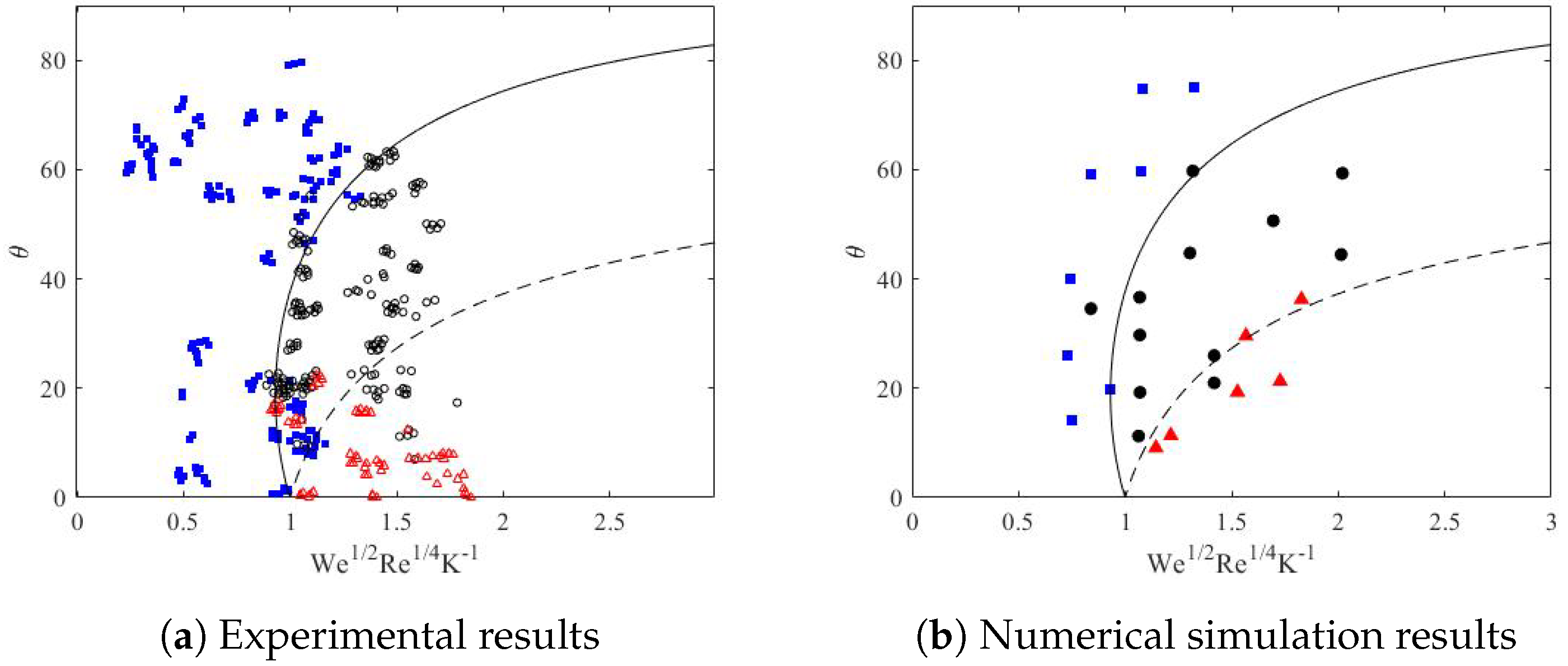
Figure 5.
Interface of a drop impingement onto a dynamic film at different impact angles.
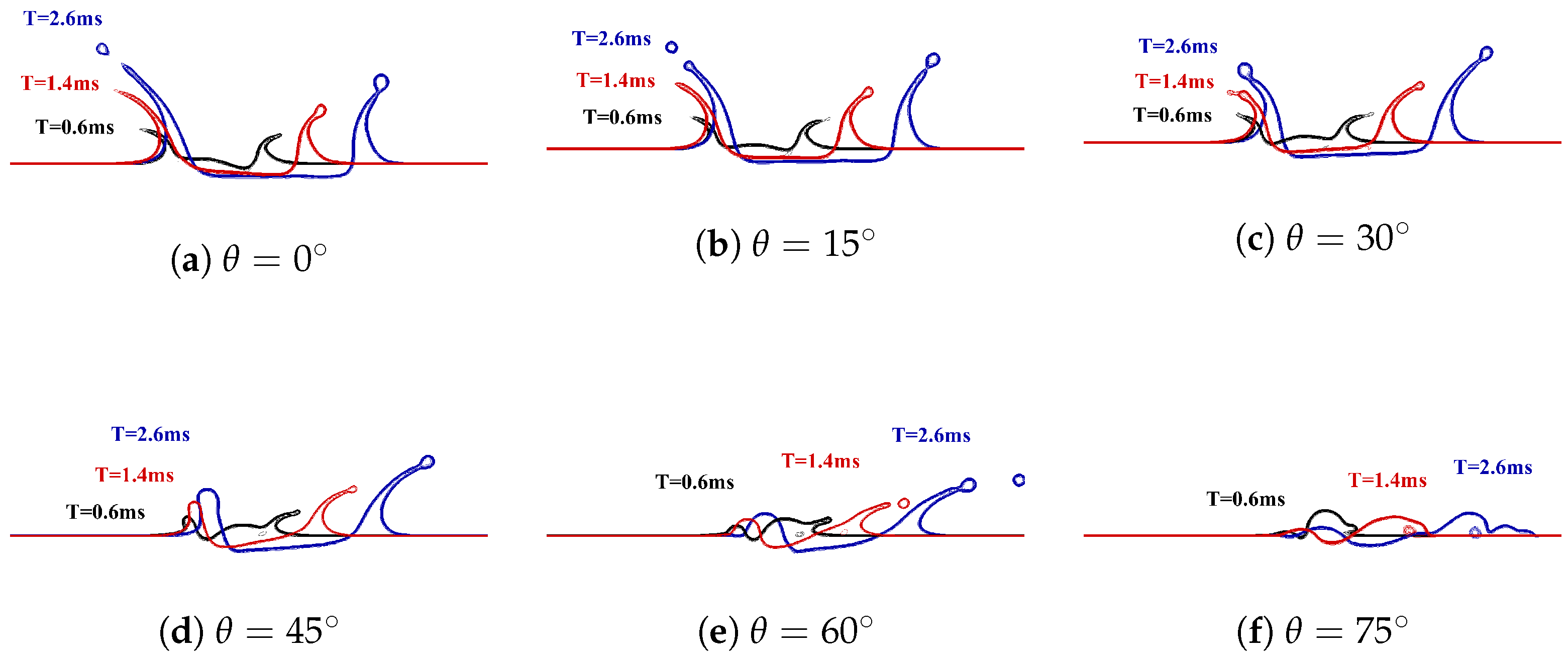
Figure 6.
Pressure field distribution at .
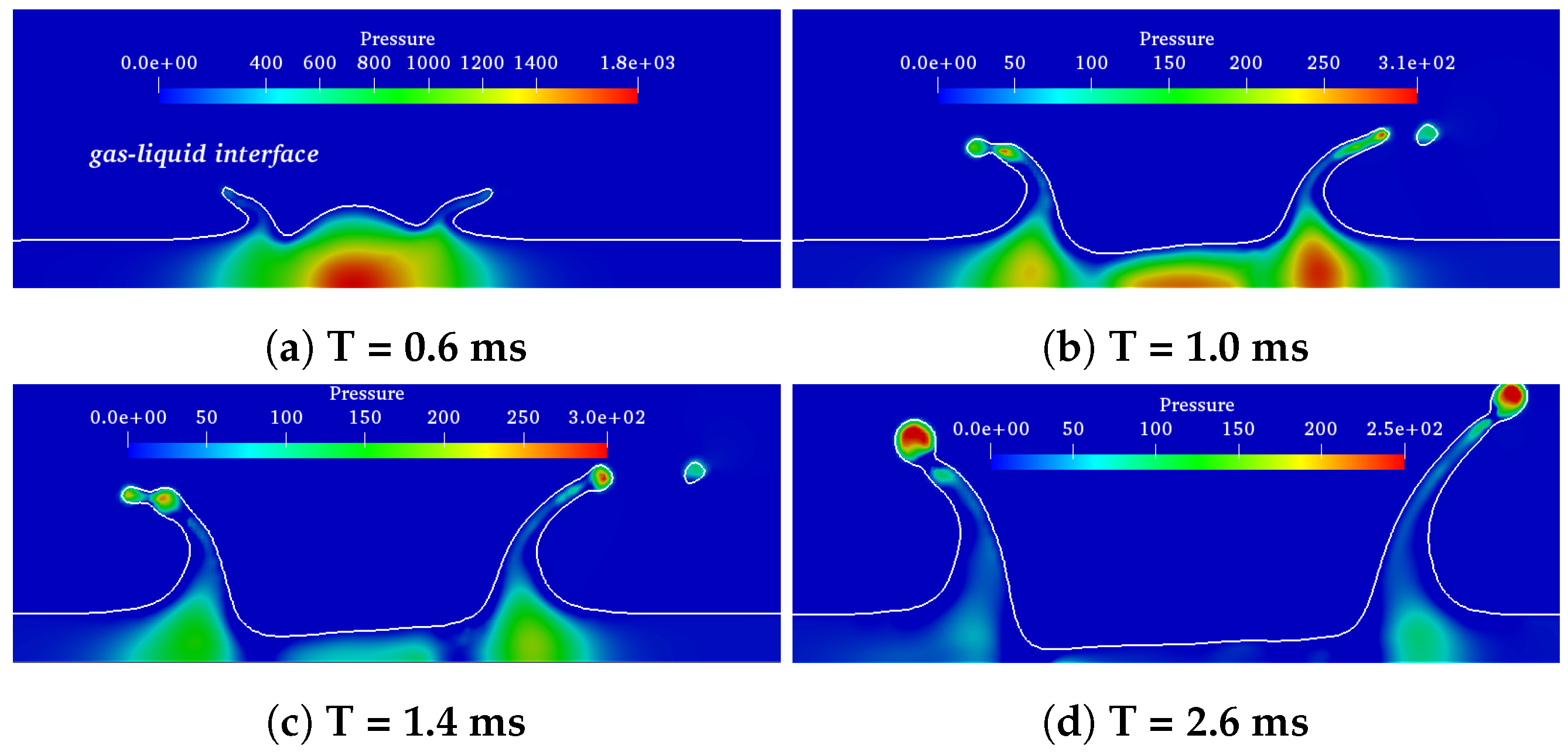
Figure 7.
Crown height of a drop impingement onto a dynamic film at different impact angles.
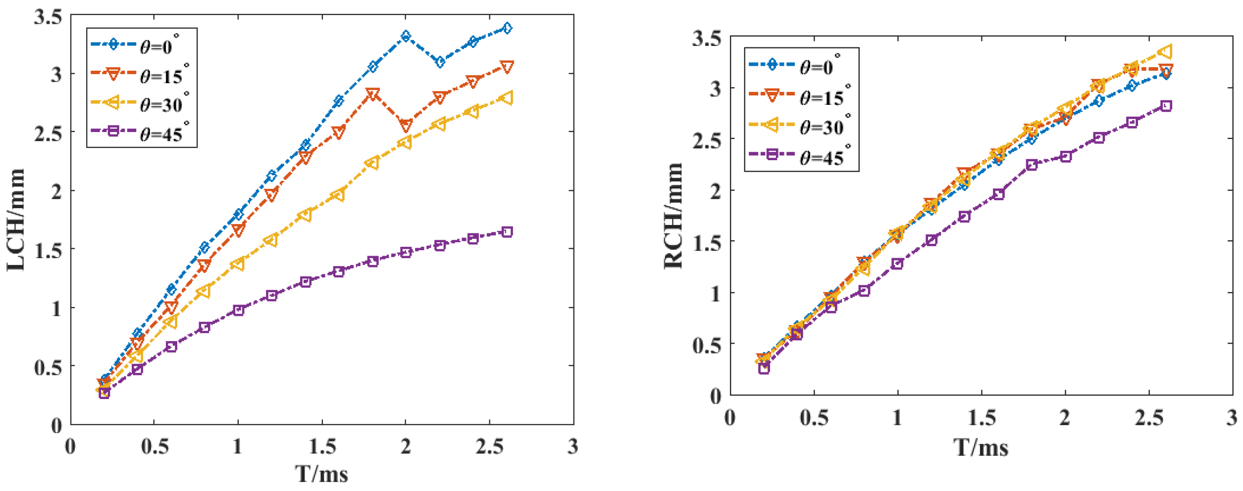
Figure 8.
Spreading length of a drop impingement onto a dynamic film at different impact angles.
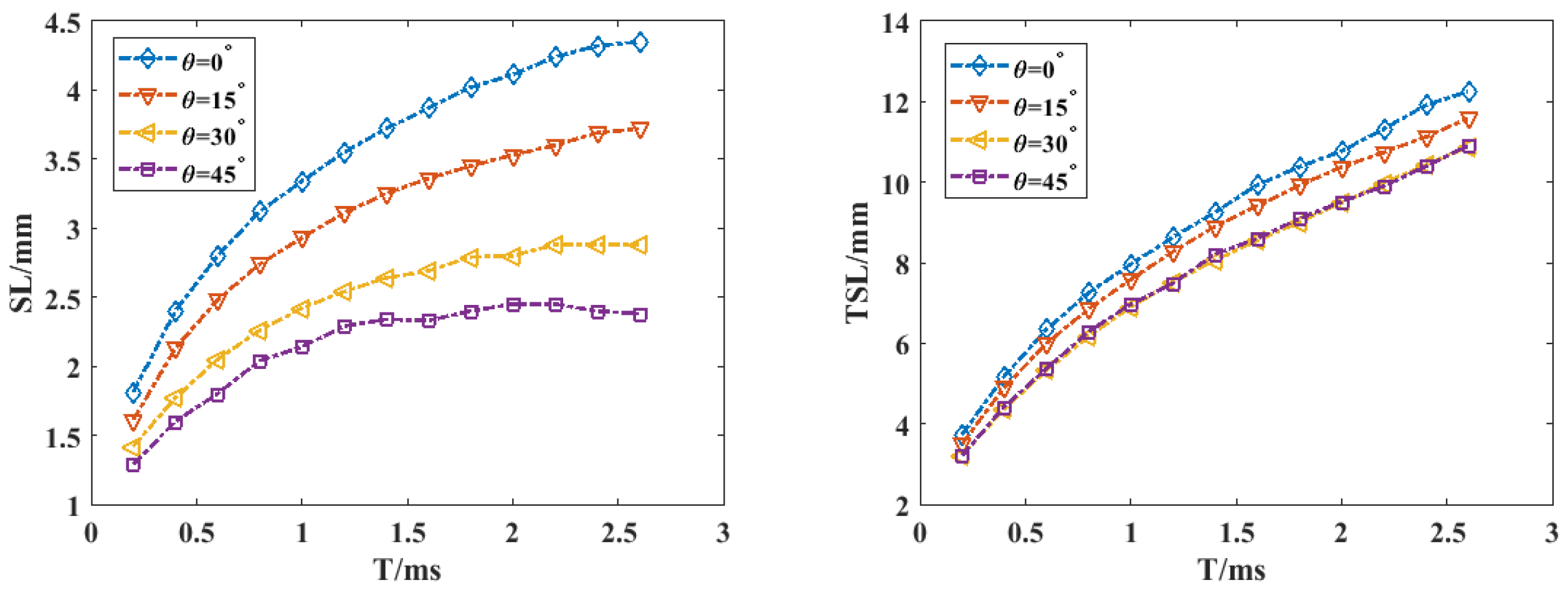
Figure 9.
Interface of a drop impact upon a dynamic film at different dynamic film velocities when .
Figure 9.
Interface of a drop impact upon a dynamic film at different dynamic film velocities when .
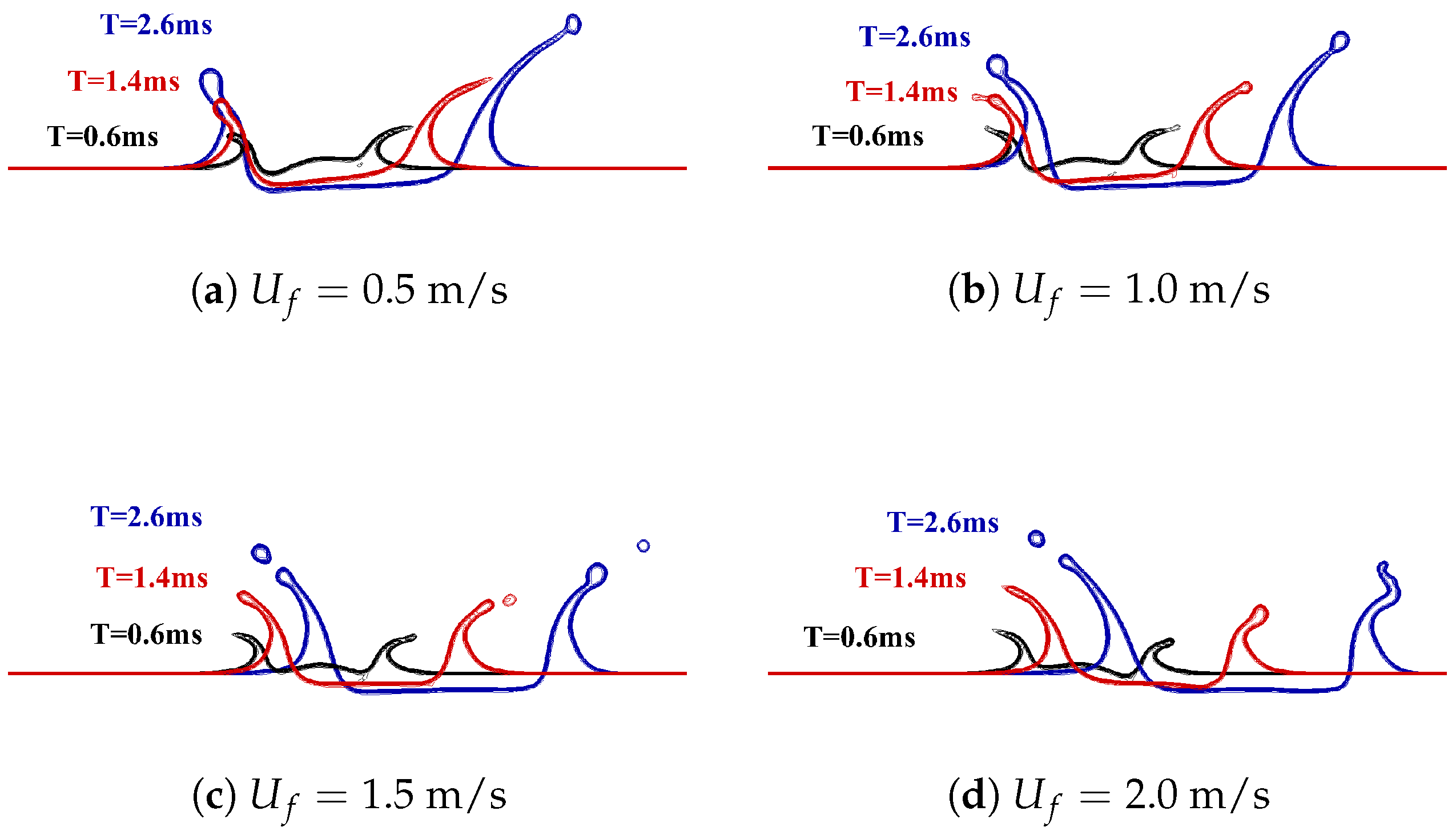
Figure 10.
Crown heights of left and right at different dynamic film velocities when .

Figure 11.
Spreading length at different dynamic film velocities when .
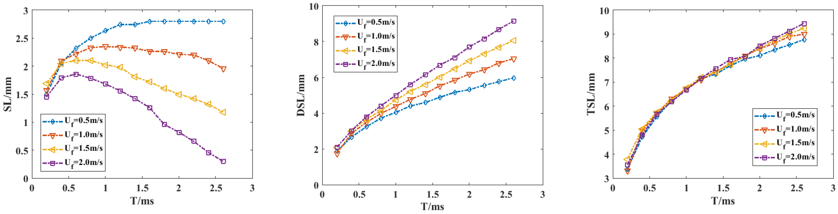
Figure 12.
Interface of a drop impact upon a dynamic film at different density ratio when .
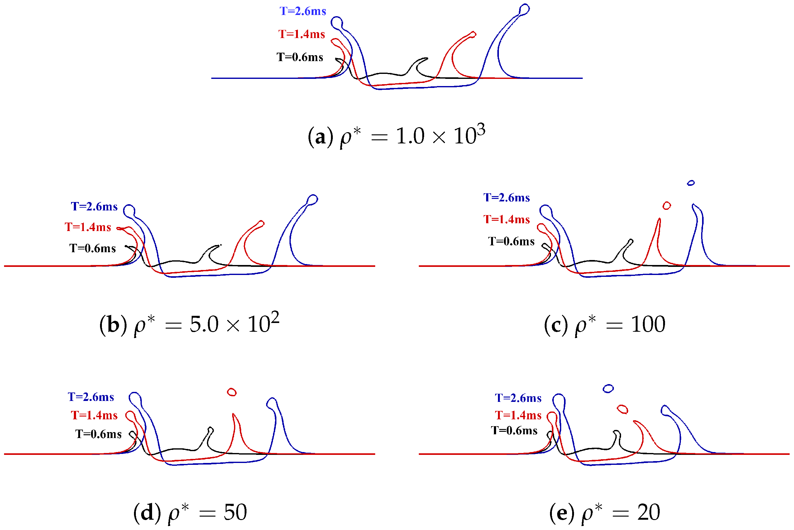
Figure 13.
Crowns heights at different density ratio when .

Figure 14.
Spreading length at different density ratio when .
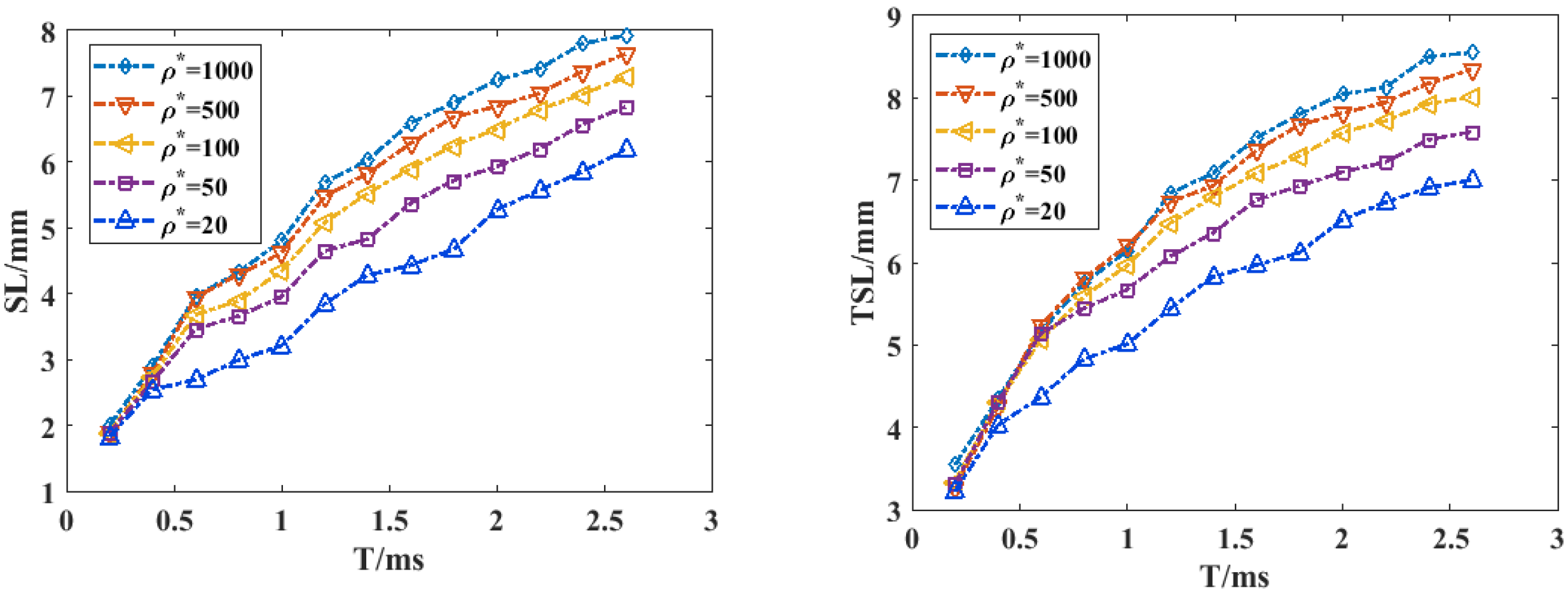
Figure 15.
Interface of a drop impact upon a dynamic film at different density ratios when .
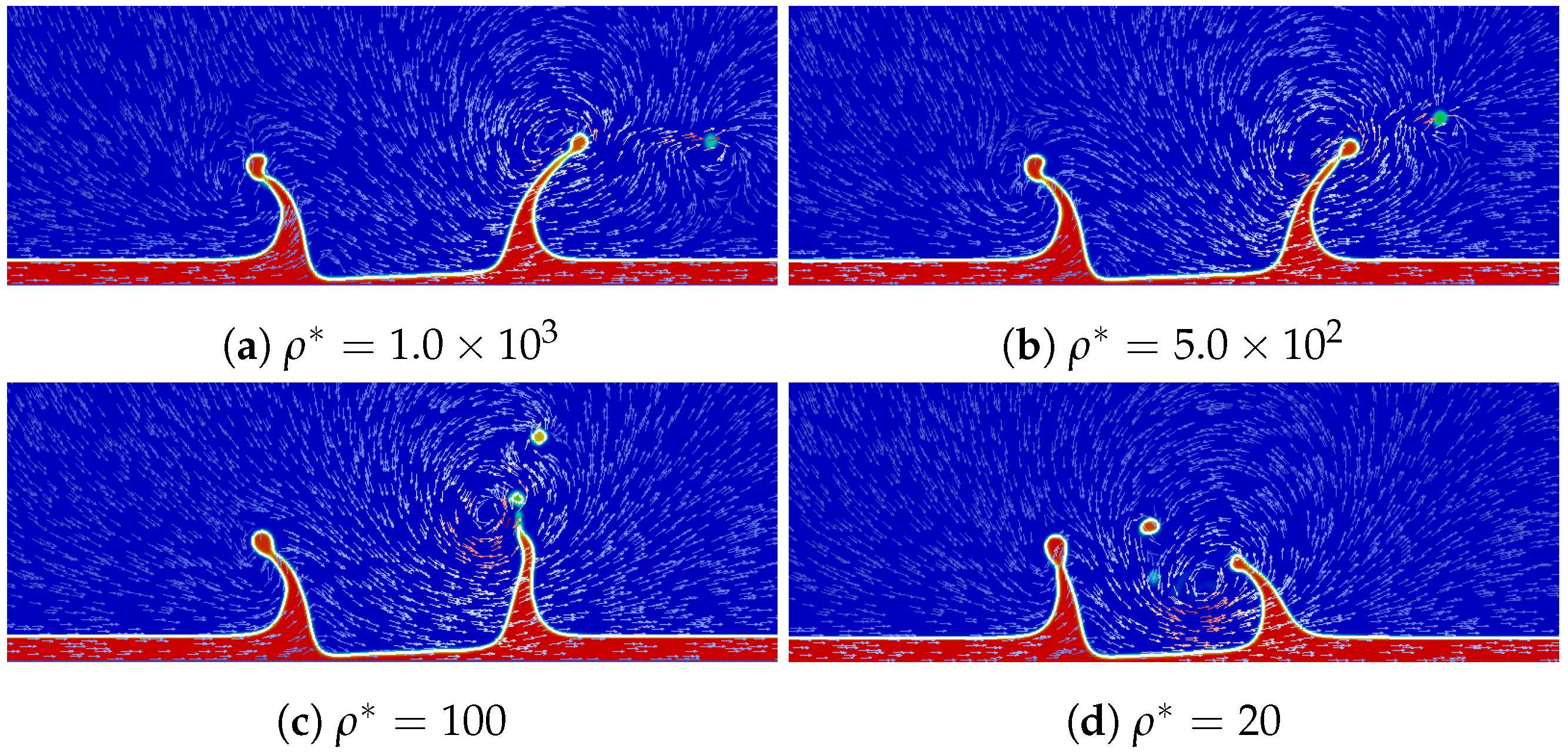
Figure 16.
Interface of a drop impingement onto a dynamic film at different viscosity when .

Figure 17.
Crowns heights at different viscosity when .

Figure 18.
Interface of a drop impact upon a dynamic film at different impact velocities when .
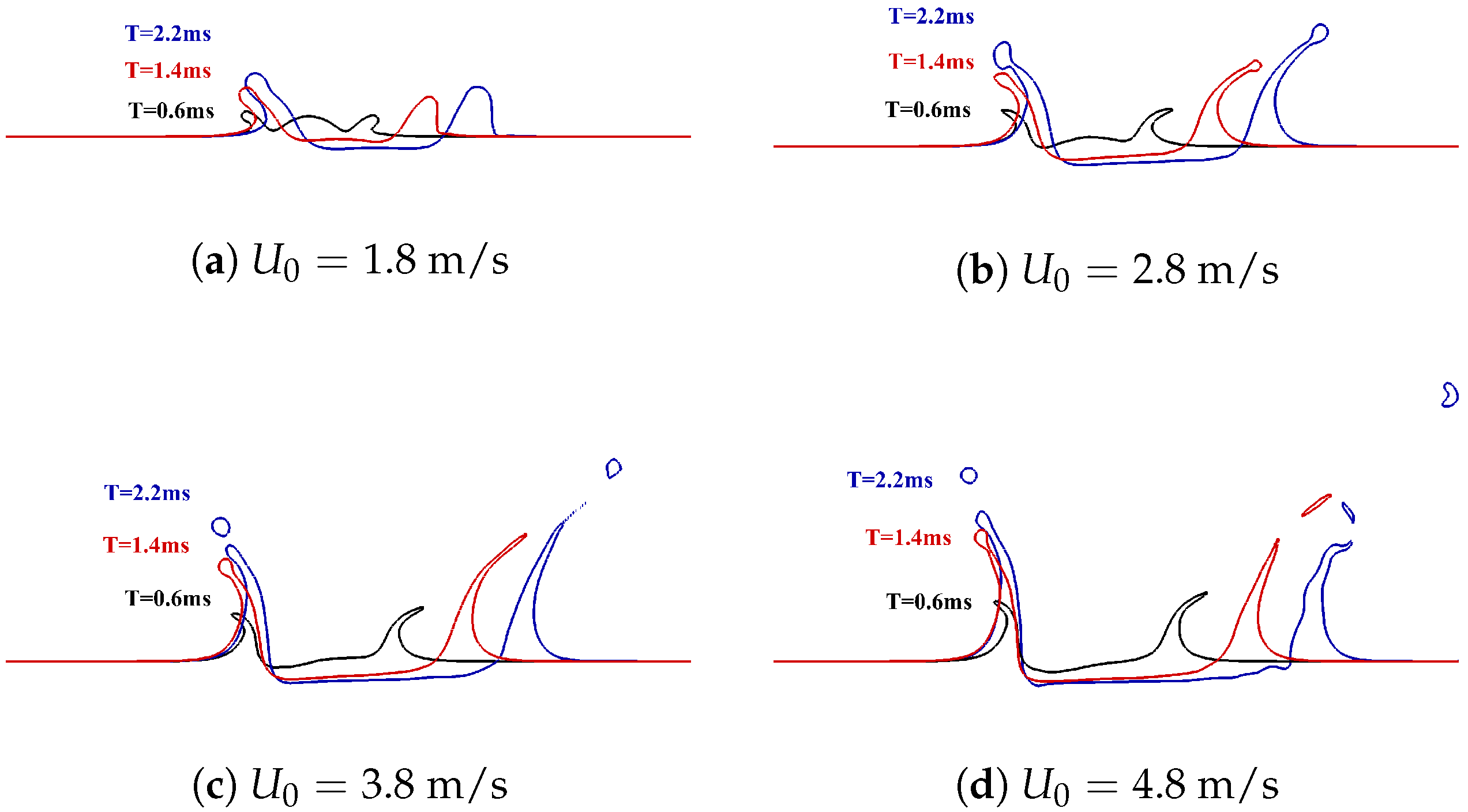
Figure 19.
Crown heights at different impact velocities when .


Table 1.
Critical parameters of numerical for each of case.
| Droplet | Film | Film | Impact | Impact | Density | Fluid | |
|---|---|---|---|---|---|---|---|
| Diameter | Velocity | Thickness | Velocity | Angle | Ratio | Viscosity | |
| Qualitative validation | 0.52 | 0 | 2 | 6.3 | |||
| 3.2 | 1.04 | 0.209 | 1.85 | ||||
| Effect of impact angle | 2.56 | 1.0 | 1.28 | 2.8 | |||
| Effect of film velocity | 2.56 | 0.5 2.0 | 1.28 | 2.8 | |||
| 1.0 | |||||||
| 1.5 | |||||||
| Effect of density ratio | 2.56 | 1.0 | 1.28 | 2.8 | 50 | ||
20 | |||||||
| 100 | |||||||
| Effect of fluid viscosity | 2.56 | 1.0 | 1.28 | 2.8 | |||
| Effect of impact velocity (Weber number) | 2.56 | 1.0 | 1.28 | 1.8 | |||
| 2.8 4.8 | |||||||
| 3.8 |
Publisher’s Note: MDPI stays neutral with regard to jurisdictional claims in published maps and institutional affiliations. |
© 2022 by the authors. Licensee MDPI, Basel, Switzerland. This article is an open access article distributed under the terms and conditions of the Creative Commons Attribution (CC BY) license (https://creativecommons.org/licenses/by/4.0/).
Share and Cite
MDPI and ACS Style
Yang, S.; Zeng, Q.; Zhang, X.; Dong, C.; Guan, L. Numerical Simulation of Single Droplet Impingement upon Dynamic Liquid Film Obliquely. Mathematics 2022, 10, 3193. https://doi.org/10.3390/math10173193
AMA Style
Yang S, Zeng Q, Zhang X, Dong C, Guan L. Numerical Simulation of Single Droplet Impingement upon Dynamic Liquid Film Obliquely. Mathematics. 2022; 10(17):3193. https://doi.org/10.3390/math10173193
Chicago/Turabian StyleYang, Shanshan, Quanyuan Zeng, Xiaohua Zhang, Chunzhu Dong, and Ling Guan. 2022. "Numerical Simulation of Single Droplet Impingement upon Dynamic Liquid Film Obliquely" Mathematics 10, no. 17: 3193. https://doi.org/10.3390/math10173193
Note that from the first issue of 2016, this journal uses article numbers instead of page numbers. See further details here.