
Equivalent Solution Method for the Analytical Transverse Modal Shape of Hollow Slab Bridges


1
School of Civil Engineering, Dalian University of Technology, Dalian 116023, China
2
School of Civil Engineering, Dalian Jiaotong University, Dalian 116028, China
*
Author to whom correspondence should be addressed.
Mathematics 2022, 10(21), 3977; https://doi.org/10.3390/math10213977
Submission received: 7 October 2022
/
Revised: 23 October 2022
/
Accepted: 24 October 2022
/
Published: 26 October 2022
(This article belongs to the Topic Development of Monitoring, Analysis and Maintenance Technics of Infrastructures)
Abstract
:Hollow slab bridges are the most widely used form of small- and medium-span bridges. The existing research on the dynamic characteristics of hollow slab bridges is mostly based on numerical models, but there is a lack of theoretical analyses of their dynamic characteristics. In this paper, the relationship between the dynamic characteristic parameters and structural parameters of a hollow slab bridge is explored theoretically. Firstly, the solid model of a hollow slab bridge was established, and a modal analysis was carried out on it as a reference. Then, an orthotropic plate was used as an equivalent dynamic analysis model, and the analytical form of the transverse modal shape was deduced based on Kirchhoff thin plate theory. Furthermore, one hinge joint was considered as being equivalent to the elastic support boundary, and the local structure and the equivalent elastic support boundary were used to reflect the transverse modal shape of the original structure. The analysis shows that the influence of hinge joints on the transverse modal shape is mainly reflected in the transmission of bending deformation. Through comparison and verification, the results show that the analytical expression of the transverse modal shape can well describe the low-order transverse modal shape of a hollow slab bridge.
Keywords:
hollow slab bridge; transverse modal shape; analytical solution; hinge joint; equivalent elastic supportMSC:
70J051. Introduction
With the development of vibration monitoring and detection methods, dynamic characteristic parameters such as frequency, modal shape, and damping of structures, which can reflect the state of structures, are gradually becoming indispensable [1,2,3]. In China, prefabricated hollow slab bridges are the most widely used among small- and medium-span bridges [4,5,6]. According to the relevant statistics from the Ministry of Transportation and Communications “Statistical Bulletin on the Development of the Transportation Industry in 2020”, there are 912,800 highway bridges in China, among which there are 786,420 small- and medium-span bridges, accounting for more than 86% of the total number of highway bridges in China. For hollow slab bridges, hinged slab theory is traditionally used to explain the mechanics of hinge joints. “Hinged slab” regards the connection between adjacent slabs as a hinge, which only transmits vertical shear force but not the bending moment. The stress state of the structure is actually close to several parallels and horizontally hinged narrow beams, and the hinge between the beams only transmits vertical shear force, while omitting the transverse bending moment, longitudinal shear force, and normal force. Zhan et al. [7] proposed a simplified analysis method of the transverse distribution coefficients of a highway simply supported by hollow slab bridges based on the hinge slab method in order to make the theoretical calculation of the transverse distribution coefficients of the bridge more consistent with the test results, and reduce the cost of the static load test. Traditional simplified models generally simplify the lateral connection of the hinge joints based on hinge plate theory and can obtain more accurate results when static checking is carried out. However, when a modal analysis is carried out because hinge plate theory only assumes that the hinge joints transmit shear force, there will be a big error in the calculation of the modal parameters. On the other hand, the analysis of modal parameters, such as the modal shape of a hollow slab bridge, is mostly based on numerical models, and its analytical form lacks the corresponding research, with the contribution of hinge joints to the modal shape also lacking a theoretical explanation. Defining the analytical form of the modal shape of a hollow slab bridge can theoretically reveal the influence of the hinge joints on the vibration characteristics of a hollow slab bridge.
Generally speaking, dynamic characteristic parameters, such as the modal shape of a hollow slab bridge are obtained based on numerical analysis [8,9]. There are many simplified models for finite element modeling. The most used simplified model is the analysis model based on the grillage method [10]. Its modeling idea is to use Euler beam elements to model a single slab girder, while the hinge joint is simulated by a virtual beam with zero mass and infinite stiffness. By releasing the end torsion constraint, it only transmits the shear force between the slab girders. Wen and Dan et al. [11,12] put forward the distributed spring multibeam model as a simplified model for the transverse connection of a hollow slab bridge. Essentially, this is still based on hinged slab theory, but the hinge joints are considered as continuously distributed springs in the longitudinal bridge direction, which only transmit the vertical shear force between the slab girders, with the slab girders and hinge joints being connected by massless rigid arms. In both models, the hinge joint is considered as only transferring the shear force between the slab girders, which is different from the actual stress mode of the hinge joint, so it still has a certain influence on the dynamic characteristics. After Xiang et al. [13] analyzed the stress mode of a hinge joint, the beam element was still used to simulate the single slab girder, and the mechanical model of the hinge joint was equivalent to two springs bearing only transverse tension and compression and a connecting rod bearing only vertical force, that is, the transmission of the bending moment by the hinge joint was considered. Zhang et al. [4] regarded the hollow slab bridge as a thin plate structure and established an equivalent orthotropic plate dynamic analysis model by calculating the longitudinal and transverse mechanical performance parameters of the hollow slab structure, taking the transverse modal shape of the hollow slab bridge as a beam modal shape function with free boundary conditions at both ends.
In this paper, based on Kirchhoff thin plate theory, the analytical form of the transverse modal shape of the assembled hollow slab bridge is solved, which can accurately describe its transverse modal shape. After the hinge joint is equivalent to the elastic support boundary, the lateral modal shape of the local structure is analytically solved, and the local modal shape can match the modal shape of the original structure, thus realizing the analysis of the hinge joint. This paper is developed according to the following structure. Firstly, the structure and mechanical characteristics of the hollow slab bridge are introduced, and the three-dimensional solid model of a hollow slab bridge is established as the reference model. Then, based on Kirchhoff thin plate theory, the analytical form of the modal shape of the hollow slab bridge is solved, the hinge joint is furtherly made equivalent to the elastic support boundary, and the local structure is used to reflect the vibration characteristics of the original structure. Finally, the analytical form of the modal shape is verified based on the reference model.
2. Dynamic Characteristics of Hollow Slab Bridge
As a bridge type that was popularized and applied on a large scale in bridge construction, the hollow slab bridge is the preferred bridge type in small–and–medium–span highway bridges because of its simple appearance, simple structure, convenient construction, and high economic benefits [14,15]. In the following, the geometric structural characteristics and mechanical characteristics of the hollow slab bridge will be introduced, and the solid three-dimensional model of the hollow slab bridge will be established as the reference model, according to the standard atlas for modal analysis and subsequent comparison. The dynamic characteristic parameter is an important basic parameter reflecting the structure. Because of its relatively high stiffness, the dynamic characteristics of small- and medium-span bridges are less affected by environmental factors, so the change of the structure itself is the main factor of its dynamic characteristics.
2.1. Structure and Mechanical Characteristics
Hollow slab bridge sections belong to slab sections. At present, in the standard drawing of a hollow slab bridge, the standard span of a prestressed hollow slab bridge is 10, 13, 16, and 20 m, and the slab width is 1 m. The slab height will increase with the increase in span, but its building height is still relatively low compared with the span and width of the whole bridge, so it can be regarded as a thin plate structure. The internal hollowing form of the slab girder is mainly a square section, and chamfering is performed at the corner. Multiple slab girders formed by lateral splicing plates contribute to the overall bearing of the vehicle load. Among the slab girders, a hinge joint, as a transverse connection structure, plays a very important role in the formation of the collaborative stress of plate girder bridges. At present, the hinge joint structure in the standard drawing is uniformly designed as a deep hinge joint, which increases the shear area of the hinge joint and improves and optimizes the lateral connection performance of the shallow hinge joint and middle hinge joint in the old design to some extent. During the construction of a prefabricated slab bridge, it is necessary to consider the size of the hinge joint when erecting precast slab girders, reserving working space, and pouring hinge joints on site. Because of the unsynchronized construction between hinge joints and precast slab girders, and the narrow working space of the hinge joint, there is a big difference between them regarding construction quality and bearing capacity, which makes it easy for hinge joints to become a weak link in actual operation [16,17].
Hinge joints are the key structures that affect the bearing capacity and operation safety of a hollow slab bridge. Here, we mainly focus on the influence of the hinge joint structure on the dynamic characteristics of a hollow slab bridge. In the traditional design of a hollow slab bridge, hinge slab theory is often adopted, and the lateral connection of the hinged joints is regarded as a hinge. That is, it is assumed that the hinged joints only form the lateral cooperative working ability between the slabs and beams by transferring shear force, while the hinged joints are subjected to the combined action of compound stress in actual operation, so there are some differences between the theoretical design of traditional hinged joints and their real working conditions. On the other hand, only hinge joints are regarded as hinges, and in terms of force transmission, they mainly transmit the shear force between the slabs; in terms of deformation, the transverse deformation is considered as shear deformation, while the transverse vibration of the hollow slab bridge is described more as a bending vibration. Therefore, when considering the transverse dynamic characteristics of a hollow slab bridge, the contribution of hinge joints to the transverse bending of the hollow slab bridge should be further considered. When the main beam of a hollow slab bridge is regarded as a thin plate structure (because of the difference in longitudinal and transverse bridge structures), the bending stiffness of the hollow slab bridge in two directions is different, meaning that the elastic characteristics in the longitudinal and transverse directions are different, so it can be regarded as an orthotropic plate [4].
Although different simplified models have different considerations for lateral connection, the simplified treatment method of a multibeam connection cannot fully reflect the structural and mechanical characteristics of a hollow slab bridge, while the solid model can fully reflect the hollow slab bridge in terms of structure and can obtain more accurate analysis results. Therefore, this paper will adopt solid model modeling as the reference model for a hollow slab bridge.
2.2. Reference Model
According to “General Drawings of Highway Bridges”, which was issued by the Ministry of Communications, the standard design drawings of prestressed hollow slabs are used to establish the hollow slab bridge with a standard span of 13 m and a bridge width of 16 m as the solid reference model. The detailed dimensions of the slab are shown in Figure 1a,b, and the cross-section is shown in Figure 1c. The transverse direction of the hollow slab bridge is composed of hinge joints numbered ①–⑮, as shown in Figure 1c and the 16 hollow slabs.
The precast hollow slab, hinge joint, and the cast-in-place layer of the bridge deck are made of C50 concrete with an elastic modulus of , a density of , and a Poisson’s ratio of . The three-dimensional solid model of a hollow slab bridge was established in ANSYS software, and its geometric model is shown in Figure 2a. A SOLID45 solid element was adopted, with horizontal and vertical dimensions of 0.06 m and 0.2 m, respectively, and the boundary conditions at both ends are simply supported. For the convenience of modeling and meshing, the modeling of the side plate is simplified, as is shown in Figure 2, meaning that the cantilever part of the side plate is not modeled. Modal analysis was carried out on the reference model, and the first six-order frequency and modal shape cloud shown in Figure 3 was obtained. The following discussion of the modal shapes is based on this reference model.
As a widely used type of small–and–medium span bridge, the existing research on the dynamic characteristics of the hollow slab bridge mainly uses a numerical model for analysis, but this seldom studies its vibration characteristics through theoretical methods. In the following, the equivalent modal shape of a hollow slab bridge will be deduced from the theoretical level, and through its equivalent model, the analytical expression of its transverse modal shape will be solved by using Kirchhoff thin plate theory.
3. Analytical Solution of the Modal Shape of a Hollow Slab Bridge
3.1. Dynamic Equivalent Model
Because of the internal hollowing out, the hollow slab bridge is not as continuous as the beam with equal section, so it is difficult to directly solve its transverse modal shape. Therefore, it is necessary to simplify and equivalent it in a certain way. As mentioned in Section 2.1, the orthotropic plate model will be used to equivalent the dynamic characteristics of hollow slab bridge in this paper. Based on thin plate vibration theory, the modal shape equation [18,19], corresponding to the free vibration of orthotropic plates, is
where is the mode shape function, which is usually set as for Lévy thin plates [20] with simply supported and free edges, a is the length of the plate in the x direction, and m is a positive integer; and are the bending stiffness in the x and y directions, respectively, , and is the torsional stiffness, is the Poisson’s ratio of the material; and are the density and height of the orthotropic plates, respectively; is the natural circular frequency.
For the above mentioned reference model (hollow slab bridge), the equivalent parameters are calculated as follows. The three stiffness parameters are , , and based on the theory of orthotropic plates, its equivalent material properties are , , , , and , with an equivalent density of ; The equivalent geometric dimensions are and the board length, a, and width, b, are the same as the original structure. The equivalent model is also established in ANSYS with SOLID45 solid element, and its geometric model is shown in Figure 4. Modal analysis was carried out on the equivalent model, and the first six-order frequencies and modal shape clouds were obtained, as shown in Figure 5.
Comparing the modal shapes of Figure 3 and Figure 5, it can be seen, intuitively, that the modal shapes of each order of the equivalent model and the reference model are similar, and it can be preliminarily concluded that the equivalent model can accurately reflect the dynamic characteristics of the solid model of a hollow slab bridge. The whole modal shapes of each order can be regarded as a combination of longitudinal and transverse bridge modal shapes. The longitudinal boundary condition of the bridge is simply supported at both ends, and the longitudinal modal shape of the bridge is similar to that of the simply supported beam. The transverse boundary condition of the bridge is that both ends are free, and the first two transverse modes are mainly the overall translational and rotational modes, followed by the transverse bending mode.
According to Equation (1), it can be seen that the mode function is mainly determined by three stiffness parameters and three material parameters, so whether the equivalent model can reflect the vibration characteristics of the hollow slab bridge depends on the calculation of several equivalent parameters. The key point of equivalence is to calculate the moment of inertia of the unit length section in the longitudinal and transverse directions of the main beam and the torsion constant of the longitudinal section. The specific calculation method has been introduced in detail in the existing literature and textbooks about the vibration theory of plates and shells [21], so it will not be repeated here. The transverse modal shape function of the equivalent model is theoretically deduced by Kirchhoff thin plate theory, and the analytical solution of the equivalent modal shape function of the hollow slab bridge is obtained.
3.2. Analytical Solution of Modal Shape
Equation (1) is a fourth-order partial differential equation with constant coefficients. When its Lévy type solution is considered, Equation (1) can be reformulated as a fourth-order constant coefficient differential equation of the transverse modal shape [22], as follows.
The general solution of this equation, meaning the general form of the transverse mode function , can be expressed as
where , and are the four constant coefficients determined by the four boundary conditions; and are the frequency coefficients which are given by the following formula.
According to Kirchhoff thin plate theory, the relationship between the four constant coefficients is obtained by solving the boundary conditions, and the analytical formula is as follows.
with
For the frequency (), the frequency equation can be obtained according to the boundary condition equation, but it is a transcendental equation, so the exact analytical expression cannot be directly solved. The approximate frequency solution can be solved based on the Rayleigh method [23], which has been introduced in detail in many pieces of literature; therefore, the detailed derivation is not carried out here.
3.3. Equivalent Boundary of Hinge Joint
As an important part of the hollow slab bridge, the whole structure can’t reflect the function of the hinge joints well when a single hinge joint is considered. Therefore, the hinge joint is further made equivalent. Similar to the equivalence of the transverse connection of the hinge joints in the previous part, if it is equivalent to the elastic connection between the slab girders, the workload of the solution will be heavy. Therefore, the hinge joint is equivalent to the elastic support boundary here. As shown in Figure 6, the original orthotropic plate is equivalent to two plates with elastic support boundaries, meaning that only the set of boundary conditions needs to be updated to obtain the analytical solution of the transverse modal shapes so that the equivalent local structure can reflect the vibration characteristics of the original structure.
Based on Kirchhoff thin plate theory, the equivalent elastic boundary condition at the hinge joint position and the free boundary condition at the hinge joint position are considered for “plate L” without losing generality, as follows.
where and are the equivalent bending moment and equivalent combined shear force at the boundary, respectively; K and k are the elastic embedded spring stiffness and the elastic shear spring stiffness, respectively, which are equivalent to the hinge joints; is the mode function of “plate L”:
Thereby obtaining the characteristic equation, as follows.
with
According to Equation (10), the analytical form of the transverse mode function is obtained as follows.
It can be seen from the that the contribution of the hinge joints is mainly the transmission of the bending deformation. The precision of the initial value of the spring parameter corresponding to the hinge joint affects whether the modal shape of the local plate is consistent with that of the original structure. Considering the equivalent elastic boundary condition, the expression of the internal force at the position corresponding to the hinge joint of the original structure is the same. Therefore, the equivalent spring stiffness is calculated by calculating the bending moment and shear internal force at the hinge joint of the original structure, and its calculation formula is as follows.
Formula and Equation (5) are substituted into Equation (13), taking to get the following formula.
where , , and are the values of the first, second, and third derivatives of at , respectively. The equivalent elastic support boundary condition is a set of corresponding spring stiffnesses, which is not equivalent to the physical elastic support boundary.
Equation (14) is substituted into Equation (12), and the analytical solution of the equivalent transverse modal shape under the elastic boundary condition of “plate L” can be obtained. For “plate R”, through the same analysis process, the analytical solution of its equivalent transverse modal shape can be obtained. Then, the transverse modal shape of the original structure is obtained by combining and according to the overall coordinates. The following numerical model will be used for comparison and verification.
4. Discussion
4.1. Modal Analysis Results
It can be seen from the first six modes of the reference model and the equivalent model established in the previous part that the first six overall modes only contain the fourth transverse modal shapes. Therefore, the transverse modal shapes represented by at the mid-span section of the longitudinal bridge are mainly compared in the following section. Table 1 shows the reference model, the equivalent model, and the frequencies and errors of the first four transverse modal shapes calculated based on the Rayleigh method. It can be seen that the frequency errors of the equivalent model and the reference model are small, meaning that the equivalent model can better reflect the modal shapes of hollow slab bridges; however, based on the approximate frequency calculated by the Rayleigh method, the error corresponding to the low order is small. When the order is relatively high, the error of the transverse modal shapes assumed by the beam function method and the transverse modal shapes of the orthotropic plate gradually increases.
Figure 7 compares the analytical solutions of the first four transverse modal shapes calculated based on Kirchhoff thin plate theory, with the numerical solutions of the reference model and the equivalent model. For the first four transverse modes, whether it is the first translational mode, the second rotational mode, or the bending mode, the error between the analytical solution and the numerical solution is very small. So, the equivalent model and its analytical solution can also accurately reflect the low–order modal shapes of a hollow slab bridge.
The comparison between the numerical results of the two important dynamic characteristic parameters, frequency and mode shape, shows that the equivalent model can accurately reflect the vibration characteristics of the solid model of a hollow slab bridge.
4.2. Modal Shape Verification under Elastic Boundary
When the hinge joint is equivalent to the elastic support boundary, Figure 8, Figure 9, Figure 10, Figure 11 and Figure 12 show the comparison between the first four transverse modal shapes of “plate L” and “plate R” and the first four transverse modal shapes of the original orthotropic plate structure. Figure 8 shows the modal shapes of “plate L” and “plate R” when the hinge joint at the center of the cross–section is equivalent to the elastic support boundary. It can be seen that the equivalent modal shapes are in good agreement with the original modal shapes. At this time, because the two plates are symmetrical, it is a special case, and it is necessary to verify the equivalence of the hinge joints at other positions.
It can be seen from Figure 9, Figure 10, Figure 11 and Figure 12 that the local modal shapes represented by “plate L” and “plate R” can also well match the modal shapes of the original structure when considering a setting of equivalent elastic boundaries at different positions. When the elastic boundary and the free boundary gradually approach, the error of the local modal shape will be relatively larger than that when , but it can still match the overall modal shape. The above verification shows that the theoretical model can well describe the transverse modal shape of a hollow slab bridge and realize the independent consideration of the hinge joints.
5. Conclusions
In this paper, an orthotropic plate was applied to the dynamic equivalence of a prefabricated hollow slab bridge, and the analytical form of the equivalent transverse modal shape of a hollow slab bridge was solved based on Kirchhoff thin plate theory. The hinge joint is equivalent to the elastic support boundary; it was verified that the local structure could reflect the vibration characteristics of the original structure by solving the transverse modal shape of the plate with the elastic boundary. Through theoretical analysis and numerical verification, the following conclusions were obtained.
- (1)
- By comparing the results of the solid model, equivalent model, and the theoretical calculation of the hollow slab bridge, the relative error of the first six frequencies was less than 5%, and the coincidence degree of the first four transverse modal shapes was very high, which indicates that the equivalent model can accurately reflect the vibration characteristics of a solid model of a hollow slab bridge; the analytical solution based on Kirchhoff thin plate theory can also accurately describe the first four transverse modal shapes;
- (2)
- The original structure is divided into two plates with elastic supporting boundaries and considering the hinge joints as the elastic boundary conditions. By solving the analytical form of the transverse modal shapes of the plate structure (simply with supported edges, free edges, and elastic supported edges) and comparing them with the transverse modal shapes of the original structure, it was verified that the local structure, with an equivalent elastic support boundary of the hinge joints, can reflect the modal shape of the original structure, indicating that the partial structure with an elastic support boundary can be used to study the hinge joints;
- (3)
- The analytical solution of the mode shape of an orthotropic plate with an elastic support boundary shows that its transverse mode shape is mainly contributed to by the equivalent elastic embedded spring, and the influence of the elastic shear spring on the transverse mode shape can be neglected;
- (4)
- When the location selection of the elastic support boundary (equivalent to the hinge joint) makes the transverse size of one of the local structures too small, it no longer meets the requirement of thin plates, yet the analytical solution of the transverse modal shape obtained based on Kirchhoff thin plate theory can still well match the modal shape of the original structure.
For the method mentioned in this paper, the hollow slab bridge under study was not damaged. Further, for a hollow slab bridge with hinge joint damage (since the modal parameters reflect the structural condition), the proposed method can analyze the damaged hinge joints and then theoretically analyze the effect of hinge joint damage on the transverse mode of the hollow slab bridge.
Author Contributions
Conceptualization, C.Q. and Y.G.; methodology, C.Q. and Y.G.; software, Y.G.; validation, Y.G.; formal analysis, C.Q. and Y.G.; data curation, Y.G.; writing—original draft preparation, Y.G.; writing—review and editing, C.Q., Y.G., L.R., R.Z. and H.L.; visualization, Y.G.; supervision, L.R., R.Z. and H.L.; project administration, C.Q.; funding acquisition, C.Q. All authors have read and agreed to the published version of the manuscript.
Funding
This research was funded by the National Natural Science Foundation of China, grant number 52078100; Fundamental Research Funds for the Central Universities, grant number DUT22JC19; Anhui International Joint Research Center of Data Diagnosis and Smart Maintenance on Bridge Structures, grant number 2022AHGHYB03; Key Laboratory of Concrete and Pre-Stressed Concrete Structures of Ministry of Education (Southeast University), grant number CPCSME2018-04.
Data Availability Statement
Not applicable.
Acknowledgments
The authors would like to extend their gratitude to the National Natural Science Foundation of China, Fundamental Research Funds for the Central Universities, Anhui International Joint Research Center of Data Diagnosis and Smart Maintenance on Bridge Structures and Key Laboratory of Concrete and Pre-Stressed Concrete Structures of Ministry of Education (Southeast University) for funding this research through various projects.
Conflicts of Interest
The authors declare no conflict of interest.
References
- Qu, C.; Yi, T.; Li, H. Modal identification for superstructure using virtual impulse response. Adv. Struct. Eng. 2019, 22, 3503–3511. [Google Scholar] [CrossRef]
- Qu, C.; Mei, D.; Yi, T.; Li, H.N. Spurious mode distinguish by modal response contribution index in eigensystem realization algorithm. Struct. Des. Tall Spec. Build. 2018, 27, e1491. [Google Scholar] [CrossRef]
- Qu, C.; Yi, T.; Yao, X.; Li, H.N. Complex frequency identification using real modal shapes for a structure with proportional damping. Comput.-Aided Civ. Infrastruct. Eng. 2021, 36, 1322–1336. [Google Scholar] [CrossRef]
- Zhang, J.; Yi, T.; Qu, C.; Li, H.N. Determining orders of modes sensitive to hinge joint damage in assembled hollow slab bridges. J. Bridge Eng. 2022, 27, 04022001. [Google Scholar] [CrossRef]
- Omar, E.; Mahmoud, E.; Ayman, K. Behaviour of prestressed hollow core slabs strengthened with NSM CFRP strips around openings: A finite element investigation. Eng. Struct. 2021, 238, 112262. [Google Scholar]
- Yi, H.; Li, C.; Dai, L. Experimental study on the shear performance of shallow hinge joints for prefabricated hollow slab bridges. Adv. Struct. Eng. 2018, 2018, 3962942. [Google Scholar] [CrossRef]
- Zhan, J.; Gao, S.; Yan, Y.; Zhou, Y. A Calculation method for transverse load distribution coefficient of highway simply-supported slab-girder bridges based on model updating. China J. Highw. Transp. 2019, 32, 72–79. [Google Scholar]
- Peng, A.; Dan, H.; Yang, D. Experiment and numerical simulation of the dynamic response of bridges under vibratory compaction of bridge deck asphalt pavement. Math. Probl. Eng. 2019, 2019, 2962154. [Google Scholar] [CrossRef] [Green Version]
- Shad, M.S.; Kenneth, K.W.; Husam, H.H.; Al Rikabi, F.T.; Steinberg, E.P. Modeling the shear connection in adjacent box-beam bridges with ultrahigh-performance concrete joints. II: Load transfer mechanism. J. Bridge Eng. 2017, 22, 04017044. [Google Scholar]
- Zhan, J.; Zhang, F.; Siahkouhi, M.; Kong, X.; Xia, H. A damage identification method for connections of adjacent box-beam bridges using vehicle-bridge interaction analysis and model updating. Eng. Struct. 2021, 228, 111551. [Google Scholar] [CrossRef]
- Dan, D.; Xu, Z.; Zhang, K.; Yan, X. Monitoring index of transverse collaborative working performance of assembled beam bridges based on transverse modal shape. Int. J. Struct. Stab. Dyn. 2019, 19, 1950086. [Google Scholar] [CrossRef]
- Wen, X.; Lei, W.; Dan, D.; Liu, G. Study on a measurement index of transverse collaborative working performance of prefabricated girder bridges. Adv. Struct. Eng. 2017, 20, 1879–1890. [Google Scholar] [CrossRef]
- Xiang, C.; Li, L.; Zhou, Y.; Dang, C. An efficient damage identification method for simply supported beams based on strain energy information entropy. Adv. Mater. Sci. Eng. 2020, 2020, 9283949. [Google Scholar] [CrossRef]
- Liu, H.; He, X.; Jiao, Y. Damage identification algorithm of hinged joints for simply supported slab bridges based on modified hinge plate method and artificial bee colony algorithms. Algorithms 2018, 11, 198. [Google Scholar] [CrossRef] [Green Version]
- Jiang, H.; Dong, X.; Fang, Z.; Xiao, J.; Chen, Y. Experimental study on shear behavior of a UHPC connection between adjacent precast prestressed concrete voided beams. J. Bridge Eng. 2020, 25, 04020106. [Google Scholar] [CrossRef]
- Xu, Z.; Dan, D.; Deng, L. Vibration-based monitoring for transverse cooperative working performance of assembled concrete multi-girder bridge: System design, implementation and preliminary application. Int. J. Struct. Stab. Dyn. 2021, 21, 2150043. [Google Scholar] [CrossRef]
- Shen, Q.; Kang, A.; Xiao, P.; Gu, W.; Jin, D.; Chen, X. Applied research on hinged joint damage evaluation of hollow slab bridge based on acceleration amplitude ratio. In Proceedings of the 3rd International Symposium on Application of Materials Science and Energy Materials (SAMSE 2019), Shanghai, China, 30–31 December 2019. [Google Scholar]
- Hsu, M. Vibration analysis of orthotropic rectangular plates on elastic foundations. Compos. Struct. 2010, 92, 844–852. [Google Scholar] [CrossRef]
- Au, F.T.K.; Wang, M.F. Sound radiation from forced vibration of rectangular orthotropic plates under moving loads. J. Sound Vib. 2005, 281, 1057–1075. [Google Scholar] [CrossRef]
- Lévy, M. Mémoire sur la théoric des plaques élastiques planes. J. Math. Pures Appl. 1877, 30, 219–306. [Google Scholar]
- Cao, Z. Vibration Theory of Plates and Shells; China Railway Publishing House: Beijing, China, 1989. [Google Scholar]
- Huffington, N.J., Jr.; Hoppmann, W.H., II. On the transverse vibrations of rectangular orthotropic plates. J. Appl. Math. 1958, 25, 389–395. [Google Scholar] [CrossRef]
- Clough, R.W.; Penzien, J. Dynamics of Structures; McGraw-Hill: New York, NY, USA, 1975. [Google Scholar]
Figure 1.
The transverse section of a prefabricated girder and hollow slab bridge (unit: mm): (a) section of side girder; (b) section of middle girder; (c) cross section.
Figure 1.
The transverse section of a prefabricated girder and hollow slab bridge (unit: mm): (a) section of side girder; (b) section of middle girder; (c) cross section.
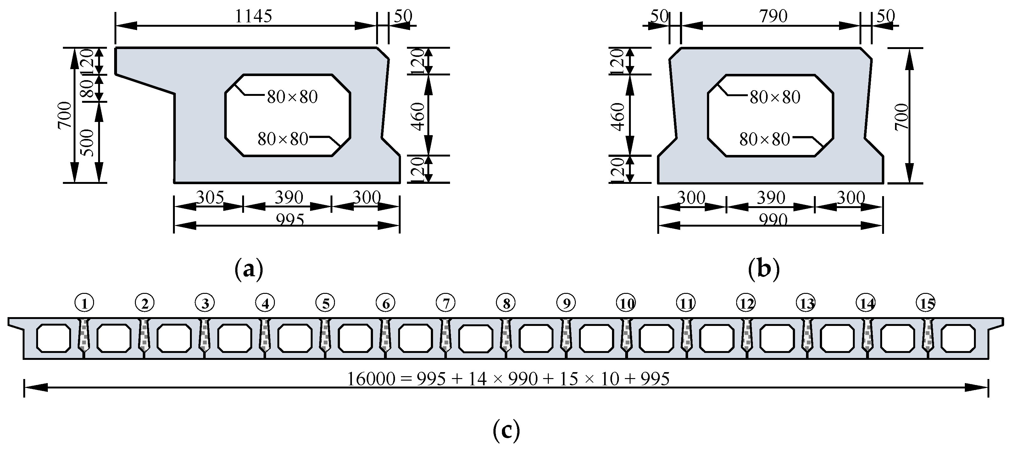
Figure 2.
The model of a hollow sab bridge: (a) geometric model; (b) finite element model.
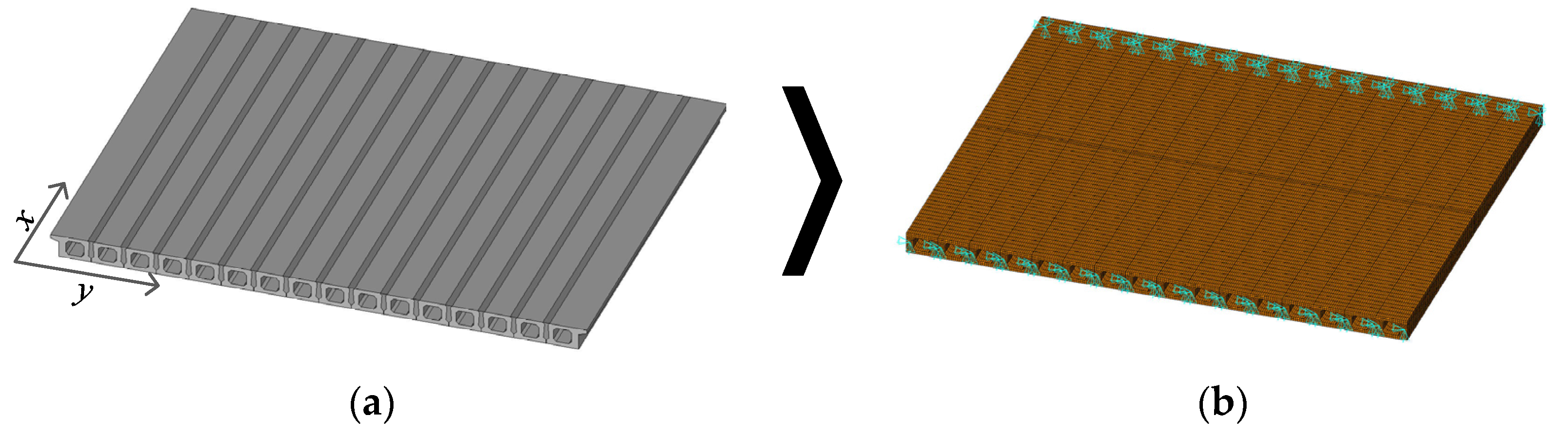
Figure 3.
First six modes of the entity model.
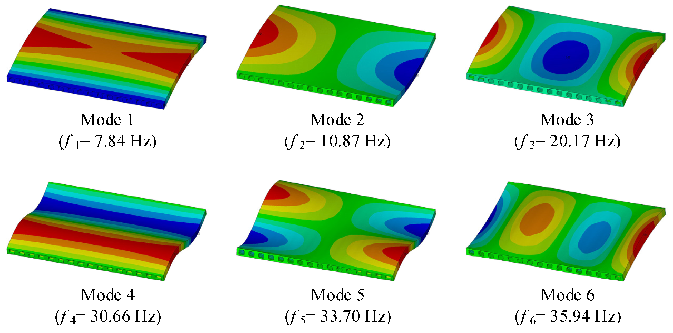
Figure 4.
The model of a hollow slab bridge: (a) finite element model; (b) equivalent orthotropic plate model.
Figure 4.
The model of a hollow slab bridge: (a) finite element model; (b) equivalent orthotropic plate model.

Figure 5.
First six modes of the equivalent model.

Figure 6.
Equivalent orthotropic plate: (a) free boundary; (b) elastically supported boundary. S: simple supported edge; F: free edge; E: elastically supported edge.
Figure 6.
Equivalent orthotropic plate: (a) free boundary; (b) elastically supported boundary. S: simple supported edge; F: free edge; E: elastically supported edge.

Figure 7.
Transverse modal shapes comparison: (a) Mode 1, n = 1; (b) Mode 2, n = 2; (c) Mode 3, n = 3; (d) Mode 6, n = 4.
Figure 7.
Transverse modal shapes comparison: (a) Mode 1, n = 1; (b) Mode 2, n = 2; (c) Mode 3, n = 3; (d) Mode 6, n = 4.
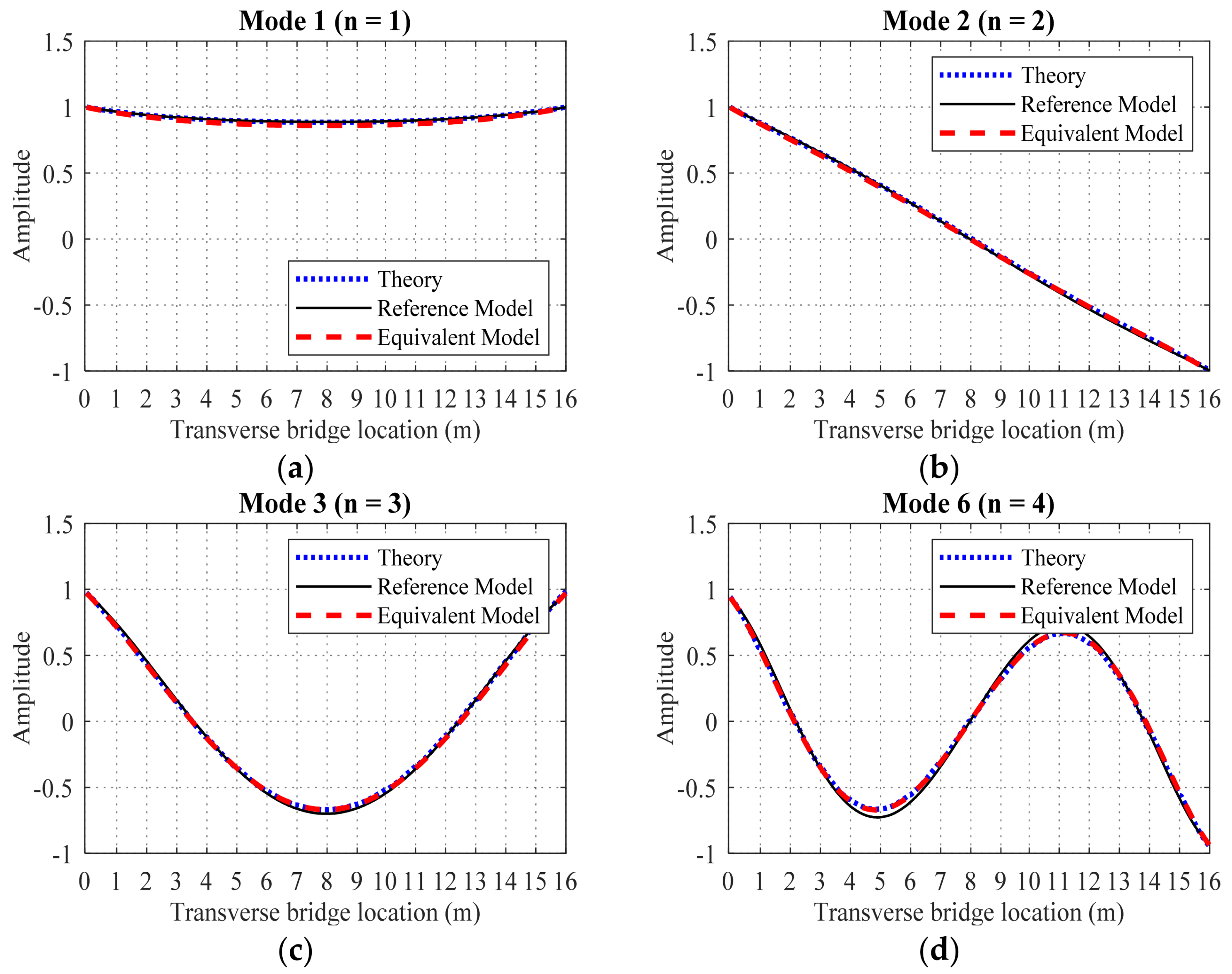
Figure 8.
Comparison of the first four transverse modal shapes: hinge position η = 8 m: (a) Mode 1, n = 1; (b) Mode 2, n = 2; (c) Mode 3, n = 3; (d) Mode 6, n = 4.
Figure 8.
Comparison of the first four transverse modal shapes: hinge position η = 8 m: (a) Mode 1, n = 1; (b) Mode 2, n = 2; (c) Mode 3, n = 3; (d) Mode 6, n = 4.
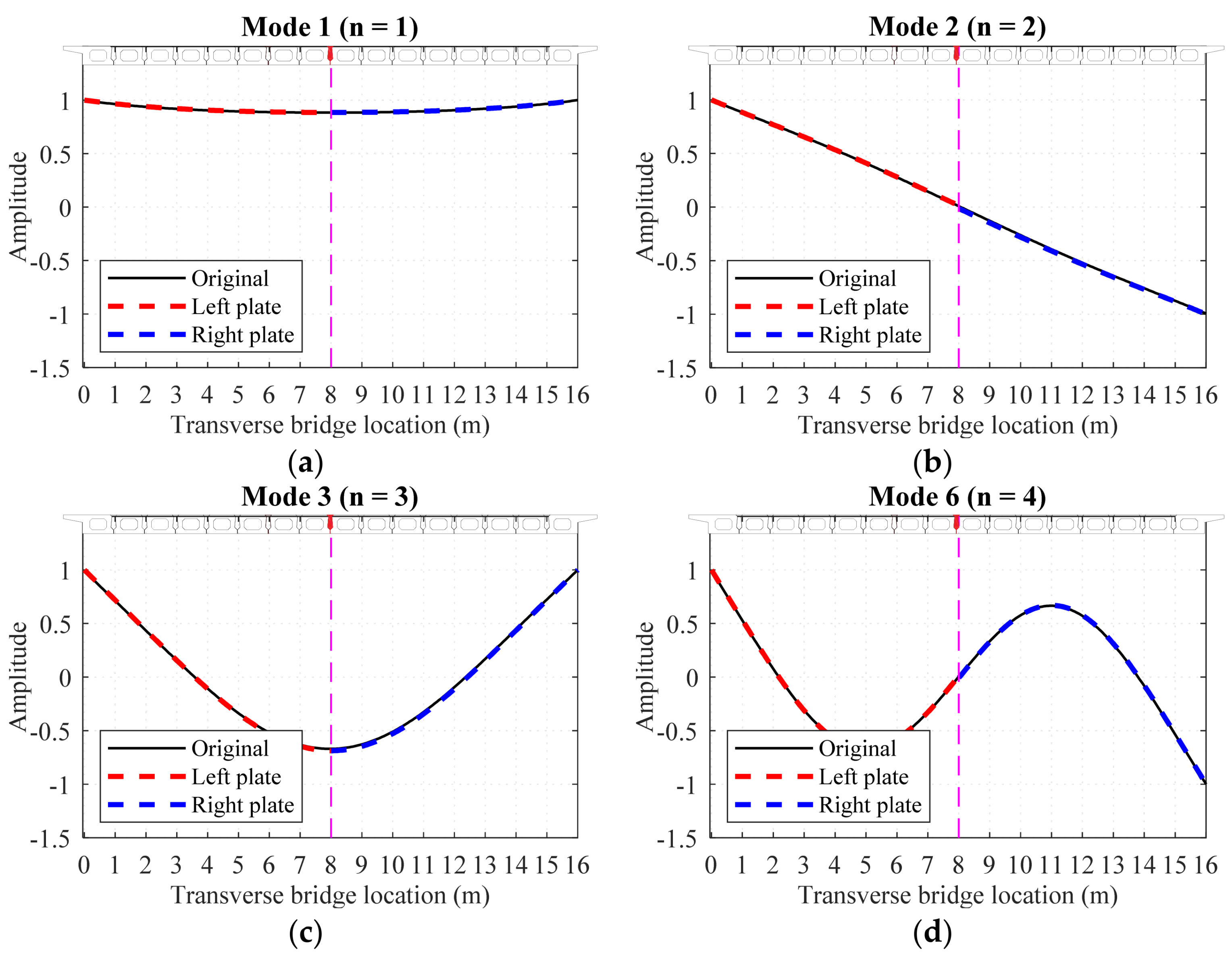
Figure 9.
Comparison of the first four transverse modal shapes: hinge position η = 9 m: (a) Mode 1, n = 1; (b) Mode 2, n = 2; (c) Mode 3, n = 3; (d) Mode 6, n = 4.
Figure 9.
Comparison of the first four transverse modal shapes: hinge position η = 9 m: (a) Mode 1, n = 1; (b) Mode 2, n = 2; (c) Mode 3, n = 3; (d) Mode 6, n = 4.
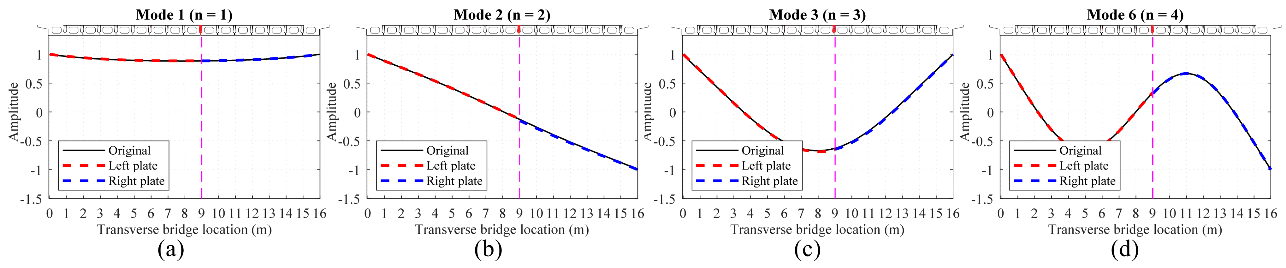
Figure 10.
Comparison of the first four transverse modal shapes: hinge position η = 11 m: (a) Mode 1, n = 1; (b) Mode 2, n = 2; (c) Mode 3, n = 3; (d) Mode 6, n = 4.
Figure 10.
Comparison of the first four transverse modal shapes: hinge position η = 11 m: (a) Mode 1, n = 1; (b) Mode 2, n = 2; (c) Mode 3, n = 3; (d) Mode 6, n = 4.

Figure 11.
Comparison of the first four transverse modal shapes: hinge position η = 13 m: (a) Mode 1, n = 1; (b) Mode 2, n = 2; (c) Mode 3, n = 3; (d) Mode 6, n = 4.
Figure 11.
Comparison of the first four transverse modal shapes: hinge position η = 13 m: (a) Mode 1, n = 1; (b) Mode 2, n = 2; (c) Mode 3, n = 3; (d) Mode 6, n = 4.

Figure 12.
Comparison of the first four transverse modal shapes: hinge position η = 15 m: (a) Mode 1, n = 1; (b) Mode 2, n = 2; (c) Mode 3, n = 3; (d) Mode 6, n = 4.
Figure 12.
Comparison of the first four transverse modal shapes: hinge position η = 15 m: (a) Mode 1, n = 1; (b) Mode 2, n = 2; (c) Mode 3, n = 3; (d) Mode 6, n = 4.


Table 1.
The calculation frequencies and error of the three methods.
| Mode Number | Order of Longitudinal Direction | Order of Transverse Direction | Reference Model | Equivalent Model | Rayleigh Method | ||
|---|---|---|---|---|---|---|---|
| m | n | fr(Hz) | feq(Hz) | fth(Hz) | Δeq | Δth | |
| 1 | 1 | 1 | 7.84 | 7.77 | 7.78 | 0.94% | 0.77% |
| 2 | 1 | 2 | 10.87 | 10.59 | 10.52 | 2.52% | 3.22% |
| 3 | 1 | 3 | 20.17 | 19.98 | 20.07 | 0.98% | 0.50% |
| 6 | 1 | 4 | 35.94 | 37.63 | 38.14 | −4.72% | −6.12% |
Publisher’s Note: MDPI stays neutral with regard to jurisdictional claims in published maps and institutional affiliations. |
© 2022 by the authors. Licensee MDPI, Basel, Switzerland. This article is an open access article distributed under the terms and conditions of the Creative Commons Attribution (CC BY) license (https://creativecommons.org/licenses/by/4.0/).
Share and Cite
MDPI and ACS Style
Qu, C.; Gong, Y.; Ren, L.; Zhang, R.; Li, H. Equivalent Solution Method for the Analytical Transverse Modal Shape of Hollow Slab Bridges. Mathematics 2022, 10, 3977. https://doi.org/10.3390/math10213977
AMA Style
Qu C, Gong Y, Ren L, Zhang R, Li H. Equivalent Solution Method for the Analytical Transverse Modal Shape of Hollow Slab Bridges. Mathematics. 2022; 10(21):3977. https://doi.org/10.3390/math10213977
Chicago/Turabian StyleQu, Chunxu, Yachao Gong, Liang Ren, Rui Zhang, and Hongnan Li. 2022. "Equivalent Solution Method for the Analytical Transverse Modal Shape of Hollow Slab Bridges" Mathematics 10, no. 21: 3977. https://doi.org/10.3390/math10213977
Note that from the first issue of 2016, this journal uses article numbers instead of page numbers. See further details here.