
Large-Scale Simulation of Shor’s Quantum Factoring Algorithm
by
 , , , and
Dennis Willsch
1,* ,
,
Madita Willsch
1,2,
Fengping Jin
1,
Hans De Raedt
1,3 and
Kristel Michielsen
1,2,4 1
Jülich Supercomputing Centre, Institute for Advanced Simulation, Forschungszentrum Jülich, 52425 Jülich, Germany
2
AIDAS, 52425 Jülich, Germany
3
Zernike Institute for Advanced Materials, University of Groningen, Nijenborgh 4, 9747 AG Groningen, The Netherlands
4
Department of Physics, RWTH Aachen University, 52056 Aachen, Germany
*
Author to whom correspondence should be addressed.
Mathematics 2023, 11(19), 4222; https://doi.org/10.3390/math11194222
Submission received: 24 August 2023
/
Revised: 29 September 2023
/
Accepted: 7 October 2023
/
Published: 9 October 2023
(This article belongs to the Special Issue Mathematical Perspectives on Quantum Computing and Communication)
Abstract
:Shor’s factoring algorithm is one of the most anticipated applications of quantum computing. However, the limited capabilities of today’s quantum computers only permit a study of Shor’s algorithm for very small numbers. Here, we show how large GPU-based supercomputers can be used to assess the performance of Shor’s algorithm for numbers that are out of reach for current and near-term quantum hardware. First, we study Shor’s original factoring algorithm. While theoretical bounds suggest success probabilities of only 3–4%, we find average success probabilities above 50%, due to a high frequency of “lucky” cases, defined as successful factorizations despite unmet sufficient conditions. Second, we investigate a powerful post-processing procedure, by which the success probability can be brought arbitrarily close to one, with only a single run of Shor’s quantum algorithm. Finally, we study the effectiveness of this post-processing procedure in the presence of typical errors in quantum processing hardware. We find that the quantum factoring algorithm exhibits a particular form of universality and resilience against the different types of errors. The largest semiprime that we have factored by executing Shor’s algorithm on a GPU-based supercomputer, without exploiting prior knowledge of the solution, is 549,755,813,701 = 712,321 × 771,781. We put forward the challenge of factoring, without oversimplification, a non-trivial semiprime larger than this number on any quantum computing device.
Keywords:
quantum computing; quantum algorithms; Shor’s factoring algorithm; high performance computing; computer simulation; parallelizationMSC:
81P68; 68Q12; 11A511. Introduction
The challenge of factoring integers is one of the oldest problems in mathematics [1,2]. Famous mathematicians such as Fermat, Euler, and Gauss have made substantial contributions to the problem, and even algorithms discovered by the ancient Greeks—the Euclidean algorithm and the sieve of Eratosthenes—are still in use today. The state-of-the-art algorithms are based on the general number field sieve [3] and have recently achieved the factorization of RSA-250 from the famous RSA factoring challenge [4]. Still, all known algorithms exhibit at best subexponential time and space complexity [4,5]. The difficulty of solving this type of problem using classical computers is an integral aspect of modern data and communication security [6,7].
In 1994, Peter Shor proposed an algorithm to factor integers on quantum computers with an exponential speedup [8,9,10] over the best known classical algorithms. Factoring an L-bit integer N with the conventional Shor algorithm [10] requires at least qubits: qubits to represent N, and qubits for the Quantum Fourier Transform (QFT), plus qubits for the modular exponentiation [6,11]. Kitaev, Griffiths, and Niu realized that by replacing the QFT with a semiclassical Fourier transform, only a single qubit can be reused t times to obtain the same result [12,13] (also known as qubit recycling [14,15] or dynamic quantum computing [16]). It is thus possible to run Shor’s algorithm with only qubits to factor L-bit integers (which is less than required by the best adiabatic algorithm [17,18]). We refer to this variant as the iterative Shor algorithm.
The iterative Shor algorithm has been executed on real quantum computing devices to factor 15, 21, and 35 [15,19,20], without relying on oversimplification [21]. Implementing the algorithm for integers beyond 35 continues to pose substantial experimental challenges [6,22].
To study the performance of Shor’s algorithm for much larger integers than those feasible for testing on real quantum devices, we have developed a massively parallel simulator called shorgpu [23], specifically designed to execute the iterative Shor algorithm on multiple GPUs. Using shorgpu, we have examined over 60,000 factoring scenarios for integers up to = 549,755,813,701, significantly surpassing previous achievements using statevector simulators [24,25,26], matrix product states [27,28] (in [28], the authors simulated 60 qubits to factor N = 961,307), and tensor networks [29,30]. Note that is still “small” for cryptographic purposes. In order to handle integers of the size of , shorgpu uses a new technique (see Section 2) to perform the distributed memory communications.
To factor , the conventional Shor algorithm would need 117 qubits. The iterative Shor algorithm, however, needs only 40 qubits. It is important to note that the resulting quantum algorithm is still an honest implementation of Shor’s algorithm: it produces the same results, does not require exponentially large classical resources (given a large enough quantum computer) and, most importantly, does not exploit a priori knowledge of the factors [21].
We emphasize that for all our simulations, we do not require the solution of the factoring problem to be known. If one presumes knowledge of the solution, and one is not interested in simulating the effect of quantum errors, it is possible to study even larger, cryptographically relevant cases using Qunundrum [31].
The procedure used to factor integers is shown in Figure 1: first, a factoring problem is selected, consisting of a semiprime to factor and a random integer comprime to N (i.e., ). Using this as input, shorgpu executes the iterative Shor algorithm with qubits to produce several bitstrings. Each bitstring j is processed using either Shor’s [8,9,10,32] or Ekerå’s [33,34] post-processing method, which may or may not produce a factor of N (see the yellow section in Figure 1). An important step on the way is to extract a candidate r for the order . Here, denotes the order of a modulo N, defined as the smallest exponent such that .
Note that “success” is not guaranteed by Shor’s algorithm; in particular, the sampled bitstring might produce an that is not the order, or r might be odd, in which case Shor’s post-processing method is not guaranteed to work. However, if the blind application of Shor’s factoring procedure still yields at least one factor, we count this execution as a “lucky” case. As shown below, a “lucky” factor is found much more often than expected.
In principle, the green section in Figure 1 representing shorgpu can be completely replaced by a sufficiently large, error-corrected quantum computing device. With this in mind, we put forward the challenge of indirect quantum supremacy [35] (a.k.a. limited quantum speedup [36]) for a future quantum computer. Here, “indirect” means that the simulator (running on a conventional computer) is required to simulate an ideal quantum computational model that executes the same quantum algorithm as the quantum computer, without using any prior knowledge of the solution. More specifically, the challenge for a gate-based quantum computer would be to factor, using Shor’s algorithm without oversimplification [21], an “interesting” semiprime—where “interesting” means that the two distinct prime factors shall have the same number of digits—that is larger than the largest semiprime that can be factored by the quantum computer simulator.
1.1. Related Work
There is a large body of literature on Shor’s quantum factoring algorithm; the related work can be roughly classified into five main categories. In this section, we give a survey of their main goals and discuss several individual results.
- 1
- Theory: the first class of articles focuses on theoretical perspectives such as algorithmic modifications and improved lower bounds on the success probability [11,14,37,38,39,40,41,42,43,44,45,46,47,48,49,50,51,52,53,54,55,56,57,58,59,60], many of which consider the case that some parameters of Shor’s algorithm are modified and certain trade-offs are made. This class contains work that estimates the number of resources required when using different levels of quantum computer technology [6,22]. This line of work culminates in Ekerå’s post-processing algorithms [34], by which the success probability for a single run of the quantum part can be brought arbitrarily close to one (see below).
- 2
- Simulation: second, Shor’s algorithm has been studied by using simulators running on conventional computers. Some use universal quantum computer simulators [24,25,26,61], sometimes also called Schrödinger simulators, since they propagate the full quantum statevector. Another approach is to use so-called Feynman simulators, which can only access certain amplitudes from the full statevector, but may require fewer computational resources; they are often based on tensor networks or matrix product states [27,28,29,30]. Finally, there is software designed to directly sample from the probability distributions generated by Shor’s algorithm (cf. Equation (26) below) and various extensions thereof. This class contains the suite of programs called Qunundrum [31,62], which can simulate distributions for large, cryptographically relevant cases. Note, however, that the solution to the factoring problem (i.e., the order or the discrete logarithm) must be known in advance, and the effect of errors in the quantum part cannot be simulated.
- 3
- Alternative Algorithms: a third line of work studies alternative ways to use gate-based quantum computers to solve the factoring problem. Some of them use Shor’s discrete logarithm quantum algorithm [62,63,64], which is also an instance of the hidden subgroup problem [65]. In the Ekerå-Håstad scheme [63], the idea to factor a semiprime is to pick a random , compute with unknown order r, and then obtain (using that [66]). If (which is the case for many g), we have , and additionally knowing allows one to compute p and q. Another alternative way to solve the factoring problem is given in [67] and is based on the classical number field sieve [3]. In particular, Bernstein et al. propose to use Grover’s quantum search algorithm [68] (and/or Shor’s algorithm for a much smaller subproblem) to accelerate the number field sieve. This proposal is asymptotically worse in time complexity than using Shor’s algorithm directly, but it requires fewer qubits and is therefore possibly easier to realize in near-term physical devices. Finally, Li et. al. [69] presented an algorithm with an exponential speedup (beyond the framework of the hidden subgroup problem [65]) that solves the square-free decomposition problem—a problem related to factoring in which the task is to find, for any integer , the unique integers and of the square-free decomposition .
- 4
- Gate-Based Experiments: fourth, there have been several experimental efforts to implement Shor’s factoring algorithm on existing gate-based quantum computer devices [15,19,20,70,71,72,73,74,75,76]. However, many of these have made use of prior knowledge about the factors to simplify the experimental setup [21]. In the extreme case (namely when a base with order is used), this reduces the computational problem to the equivalent of flipping coins. Experiments that have not used such an oversimplified method can be found in [15,19,20].
- 5
- Other Experiments: finally, quantum annealers and adiabatic quantum computers have been used to study alternative factoring algorithms [17,77,78,79,80,81,82]. The quantum annealing approach requires at most qubits to factor an L-bit number. Quantum annealing and adiabatic quantum computation are technologically significantly ahead of gate-based quantum computing, in that larger quantum processing units with more than 5000 qubits exist and that they can solve much larger problems [83,84]. In particular, numbers up to and above 200,000 have been factored on the D-Wave 2000Q [78,79] and 1,005,973 has been factored using D-Wave hybrid [80]. Although significantly larger than the numbers factored on gate-based quantum computers (without oversimplification), these numbers are still much smaller than = 549,755,813,701 factored in this work using shorgpu.
1.2. Outline
This paper is structured as follows. In Section 2, we describe the algorithmic details of shorgpu. In particular, we explain how to implement the modular multiplication as a systematic communication scheme between the compute nodes. In Section 3, we present our results from over 60,000 quantum computer simulations using up to 2048 GPUs. Section 4 contains our conclusions.
2. Materials and Methods
For almost all results reported in this work, we use shorgpu to simulate the iterative Shor algorithm (the source code is available online [23]). It propagates an -qubit statevector consisting of complex numbers through the quantum circuit for factoring an L-bit number shown in Figure 2. Each step in the quantum circuit corresponds to an operation on . In this section, we describe each of these operations in a linear algebraic context. The probability distribution generated by Shor’s algorithm is derived and visualized in Appendix A.
As the total memory is the bottleneck of such statevector simulations, the complex numbers are distributed over the memory of up to 2048 GPUs (cf. Figure 1). Communication between the GPUs is managed using the Message Passing Interface (MPI) [85].
We use the Jülich Universal Quantum Computer Simulator (JUQCS) [24,25,86] for verification. JUQCS was previously used to simulate the conventional Shor algorithm for 65,531 with up to qubits on the Sunway TaihuLight and the K computer [25]. A few features had to be added to JUQCS to be able to also simulate the iterative Shor algorithm. The latter made it possible to simulate one bitstring for N = 4,194,293 with qubits in about 720 s (using four A100 GPUs). However, our JUQCS implementation of the oracle which performs the modular exponentiation becomes highly inefficient as the number n of qubits increases because it does not distribute well over many cores or GPUs. In contrast, the new, dedicated algorithm described below generates a bitstring in about 0.4 s for the same problem and the same number of GPUs. For the largest problem simulated (N = 549,755,813,701 with qubits), shorgpu generates a bitstring in about 200 s using 2048 GPUs. We verified that the iterative Shor algorithm simulated with shorgpu produces the same results as JUQCS for problems of the size that can be simulated with JUQCS.
2.1. Initialization
To simulate the iterative Shor algorithm for factoring an L-bit semiprime N, shorgpu simulates the full quantum circuit with qubits shown in Figure 2. This is conducted by computing all complex coefficients of the statevector
These complex double-precision numbers are distributed over GPUs. The distributed memory communication between the GPUs uses CUDA-aware MPI. In our approach, each GPU is identified by its MPI rank, i.e., an -bit integer called . Here, denotes the number of so-called global qubits (see [24,25,86]). We have GPUs. The other qubits are called local qubits, since each GPU holds in its local memory all complex coefficients
The GPUs (i.e., the MPI processes) are further divided into two separate groups, identified by the most significant bit of the MPI rank,
Here, identifies the group and identifies the GPU within each group. Thus, shorgpu requires at least two GPUs to work (unless a single GPU is used with 2 MPI processes in overscheduling mode). The reason for the separation into two groups is that the implementation of the controlled modular multiplication gate (see below) requires an all-to-all communication between all GPUs with .
At the start of the simulation, the statevector is initialized in the state , where . This means that we set
and all other coefficients to zero. This type of initialization is always used unless shorgpu is used to assess the effect of quantum initialization errors (for information on this mode, see Section 2.6 below).
2.2. Controlled Modular Multiplication Gate
The first gate in each of the t stages in Figure 2 is the controlled modular multiplication gate (also called oracle gate), controlled by the first qubit. Mathematically, its operation is defined by
where x denotes the first qubit, denotes the other qubits, and stands for one of the powers of a in Figure 2. Note that each individual modular exponentiation is always precomputed for any realization of this circuit (we use the shift-and-multiply algorithm). This is independent of whether the circuit is executed by a quantum computer simulator or a real quantum computer (see also [6,19,20]).
Looking at Equation (6), we see that the oracle gate performs a permutation of all complex coefficients among the GPUs in the group. shorgpu implements this unitary operation by computing, on each GPU, all indices of the coefficients that are sent to other GPUs (stored in a GPU buffer oracle_idxsend) and those that are received from other GPUs (stored in a GPU buffer oracle_idxrecv) using the precomputed modular inverse , which is efficiently computable using the extended Euclidean algorithm. The MPI communication scheme for an example with 16 GPUs is shown in Figure 3.
The complexity of the permutation depends on the value of a. For instance, in the special case that the order of a is a small power of 2, we have in many of the early stages, so the oracle gate would not require MPI communication between different GPUs. In general the communication scheme can be very complicated. Figure 3 shows a typical instance where each GPU sends (red arrows) and receives (blue arrows) some coefficients from other GPUs.
To implement this communication scheme between the GPUs, shorgpu uses non-blocking point-to-point communication in a circular fashion using MPI_Isend and MPI_Irecv. Additionally, before the send operations, each GPU first arranges all coefficients that are sent to a particular other GPU in a contiguous block of memory, schematically denoted by . This is imperative since for large N, this part of the simulation takes a significant fraction of the total run time. Alternative implementations using one-sided communication such as MPI_Put, collective communication using MPI_Alltoallv, or communication based on custom MPI data types (see [85] for more information) performed significantly worse in our experiments.
2.3. Rotation Gate
After the oracle gate, each stage (except the first stage) of the quantum circuit in Figure 2 contains a sequence of rotation gates defined by
These are controlled by bits resulting from previous measurements. Specifically, at the stage , in which the classical bit is being measured, the sequence of these controlled rotation gates reads
where the phase at stage amounts to
and is the integer assembled from all classical bits measured up to this point.
As the phase gate given by Equation (8) only affects coefficients where the first qubit index , this operation only needs to be implemented by the GPUs in the group. This is performed directly after the implementation of the oracle gate, when moving all coefficients out of the contiguous memory blocks , according to
2.4. Hadamard Gate
The implementation of the Hadamard gate on the first qubit transforms the statevector coefficients as
For every GPU in the group, this requires two-sided MPI communication with exactly one GPU in the group.
2.5. Measurement Operation
At the end of each stage in Figure 2, the classical bit is measured, where enumerates the stage. This amounts to adding up the probabilities
which is an MPI reduction over all GPUs belonging to the group. The probability to measure 1 (0) is then given by (). This probability can be used to sample , which is performed by drawing a uniform random number , and assigning if this and otherwise.
2.6. Reset Operation
The reset operation performs both the von-Neumann projection of the statevector to the result of the measurement and the reinitialization of the first qubit in at the same time. If the result of the measurement is given by , this operation is performed by transforming all coefficients according to
Of course, in the case of quantum errors, the coefficients have to be replaced accordingly (cf. Equations (25a) and (25b)).
This operation requires an MPI transfer of all coefficients from the GPUs in the group to the GPUs in the group .
2.7. Initialization Errors
There are two different types of initialization errors that shorgpu can simulate, namely an amplitude initialization error and a phase initialization error. In both cases, a slightly different initial state is used instead of for the first qubit in all stages of the circuit in Figure 2. The slightly erroneous state is parameterized in terms of an error parameter . Our motivation to prioritize the recycled qubit for a study of initialization errors instead of the other “internal” qubits is that this qubit is measured and reinitialized successively in every stage of the iterative Shor algorithm.
2.7.1. Amplitude Initialization Error
We define an amplitude initialization error as the case in which, at the beginning of each stage in Figure 2, the quantum state is not initialized in the equal superposition but the slightly unequal superposition
This expression is motivated by the observation that quantum computer prototypes from the NISQ era sometimes tend to prefer over when brought to a uniform superposition by multiple quantum gates [87]. Furthermore, one of the most prominent decoherence and noise processes in qubit systems is a decay from to , a so-called relaxation process [88,89,90].
2.7.2. Phase Initialization Error
2.7.3. Effective Single-Qubit Error Probability
For both initialization errors, the error parameter can be related to an effective, single-qubit error probability, defined as the probability that the erroneous state would correctly be observed as a state when measured along the x axis:
Note, however, that this interpretation is not unique; depending on the particular realization of the quantum circuit, there may be more reasonable, alternative interpretations of in relation to an effective error probability.
2.8. Measurement Errors
For quantum processors, a measurement is often a slow and susceptible process by which destructive influences from the environment can enter the quantum system [92,93,94,95,96]. Moreover, it is particularly challenging to implement quantum non-demolition readout required for midcircuit measurements [16,97]. We distinguish between two different types of measurement errors, namely a classical error corresponding to a misclassification of the quantum measurement result, and a quantum error that may occur during or before each measurement.
2.8.1. Classical Measurement Error
We define a classical measurement error as a misclassification that occurs right after the quantum measurement process with a given, constant error probability . It is defined by flipping only the resulting bit , while leaving the internal quantum state unchanged.
Simulating a classical measurement error requires a second sampling step, by drawing another uniform random number and flipping the bit if . In case of a misclassification error, we simply use for the classical bitstring in Figure 2. The quantum state, however, is left in its original state with the first qubit projected on .
Note that even such a single misclassification error can have non-trivial consequences, since this error affects the angles of all subsequent rotation gates (see Figure 2). This has an influence on the measurements of the following bits . Therefore, a single bit flip error can induce a change in more than one classical bit of the output bitstring j.
2.8.2. Quantum Measurement Error
Quantum errors are conventionally modeled as operations on the system’s density matrix . If such an operation is a completely positive, trace-preserving map, it is called a quantum channel or error channel (see [32,98,99] for more information).
We model a quantum measurement error by applying a depolarizing error channel in every measurement process (which, on quantum computer hardware, is a time evolution that can take a significant amount of time [96]). The depolarizing error channel is defined by the quantum operation
where is a single-qubit density matrix, are the Pauli matrices, and represent the error probabilities for the respective Pauli errors. After the application of to the first qubit, the density matrix that describes the state of the full quantum computer reads
where I is an identity operation on the remaining L qubits, and enumerate their different indices.
A measurement of the first qubit is quantum-mechanically described by the measurement operators and . Using Equation (20), we find the probability to measure as
where is computed according to Equation (14). A calculation of the post-measurement state yields
where
and
Here, the superscript “correct” (“error”) refers to the probability and the state in the case that no error (an error) has occurred. Furthermore, the expressions show that both Pauli x and y errors only occur in combination, so we define the joint quantum error probability , by analogy with the classical case.
As in the classical case, a simulation of the quantum error process requires two sampling operations: first, a random number is sampled to assign the measurement result with probability given by Equation (22), i.e., we assign if this and otherwise.
Second, a random number is sampled to determine whether an error has happened or not. If , an error has happened while measuring , and the simulation continues with the state given by Equation (25b). Otherwise, the simulation continues with the state .
Note that the quantum error has a more direct influence on the quantum state than the classical error, since the projection to either or directly affects the quantum state, not only implicitly through the angles of subsequent rotation gates.
2.9. Details on Memory and Computing Time
The largest part of the memory needed by shorgpu is taken by the coefficients of the statevector (see Equation (1)). For a 40-qubit iterative Shor circuit, which can be used to factor 39-bit integers, the statevector needs complex double-precision floating point numbers, so . For performance reasons, two statevector buffers are used in the implementation of the oracle gate and the following single-qubit gates. In addition to the two statevector buffers, shorgpu requires two 32-bit integer buffers for the implementation of the oracle gate, called oracle_idxrecv and oracle_idxsend (see above). Each of these takes another . The total GPU memory required is thus slightly larger than . When using GPUs, the required memory per GPU is slightly larger than .
We performed all simulations on JUWELS Booster [100,101], a GPU cluster with 3744 NVIDIA A100 Tensor Core GPUs [102], each of which has of GPU memory. Note that the implementation of the algorithm requires the number of GPUs to be a power of two (cf. Section 2.1), so the maximum number of NVIDIA A100 GPUs that we can use on JUWELS Booster is 2048. The total computing time used to perform the simulations amounts to 594 core years (corresponding to 49.5 GPU years since each node contains four A100 GPUs and 48 physical CPU cores). We note that the total computing time is of the 2700 core years used for the recent factoring record of RSA-250—a number with 829 binary digits from the famous RSA factoring challenge [4].
3. Results
In this section, we describe and interpret the results obtained from simulating Shor’s algorithm according to Figure 1. For our analysis, we generated 61,362 factoring problems , 52,077 of which were chosen to have uniformly distributed prime factors to ensure unbiased results, and the rest comprise individual factoring problems for large semiprimes (see Appendix B). We consider Shor’s original post-processing in Section 3.1 and Ekerå’s post-processing in Section 3.2.
3.1. Using Shor’s Post-Processing
A given factoring problem for Shor’s algorithm consists of a semiprime N and a random integer coprime to N. For each such factoring problem , Shor’s algorithm produces a sample of M bitstrings (we typically consider samples). Each bitstring j is analyzed using the so-called standard procedure (see Appendix C). If all checks on j from the standard procedure pass, the algorithm was successful and we count the bitstring j as “success”. However, if certain checks on j fail, we still evaluate j and test if it yields a factor of N. If it does, we count this factoring attempt as “lucky”. Figure 4a shows a scatter plot of all “success” and “success+lucky” probabilities for all uniformly distributed problems ( qubits) and the individual large problems ( qubits).
Surprisingly, “lucky” occurs much more often than expected. In Figure 4b, we see that on average only of all bitstrings yield “success”. Including the “lucky” cases, however, a factor of the semiprime N can be extracted from over of all bitstrings on average. Additionally, all average success probabilities are significantly larger than the theoretical bound of 3–4% (see Appendix A.2). We hypothesize that asymptotically, the average success probability for “success + lucky” approaches from above (further evidence is given in Section 3.1.1 below, where we give a classification of the different “lucky” scenarios and show that the main contribution saturates around ). This observation is remarkable, as it shows that factoring a semiprime with Shor’s algorithm is often successful, even though the order-finding procedure actually fails.
Simulating Shor’s algorithm for semiprimes N between 536,870,861 and 549,755,813,701 requires substantial computational resources. Therefore, only individual cases are shown in Figure 4a. These cases correspond to the largest “interesting” semiprimes for a given number of qubits . A noteworthy case is the factoring problem for = (8,589,933,181, 3,974,323,683) ( qubits). Here, the “lucky” cases raise the success probability from to (yellow square) among all M bitstrings. Furthermore, the factoring problem for = (274,877,906,893, 226,009,433,972) ( qubits, second from the right) has a success probability of when the sufficient conditions for Shor’s algorithm are presupposed (green circle). However, when ignoring the violations of these conditions, we find that Shor’s algorithm can indeed factor N with a “lucky” success probability of (yellow squares).
The unexpectedly large success probabilities when the lucky cases are included prompt the question “how many bitstrings do we need to sample until a factor is found?” This is a relevant question, since for large problems, computing time on both classical and quantum computers is an essential resource. Figure 5a demonstrates that, for more than half of all factoring problems examined, the first sampled bitstring already yields a factor of N. Furthermore, in only of all factoring problems , none of the 1024 bitstrings produced a factor. In this case, the reason is usually that the choice of a was bad, which can be estimated to happen with probability 50% (see Proposition A3 in Appendix A.2). Clearly, the failure probability of is much smaller than the theoretical estimate would suggest.
Figure 5b further reveals that, even when the order-finding procedure in Shor’s algorithm fails, the first bitstring often still produces a factor. In of all cases, the first bitstring yields the order of a modulo N (leftmost bar). From Figure 4b, we know that on average, of all factoring problems can be solved after the order is known (blue triangles). Thus we expect approximately of all factoring problems to be solved by the correct order after the first bitstring. However, in Figure 5a, we see that of all problems are solved by processing the first bitstring. This percentage obviously is much larger than , implying that it is easier to find a factor with Shor’s algorithm than to solve the underlying order-finding problem.
Another interesting result is observed when reducing the number of bits t in the sampled bitstring below the recommended (cf. Appendix C). This saves resources in both versions of Shor’s algorithm. For the conventional Shor algorithm, it reduces the required number of qubits and gates required for the QFT. For the iterative Shor algorithm, it linearly reduces the number of quantum gates and thus the execution time.
Surprisingly, in almost all cases, reducing the number of bits t still allows for a successful factorization. Three representative cases are shown in Figure 6. First, Figure 6a shows that reducing t may even increase the frequency of “lucky” factorizations to over , as it does for in this case. Second, in Figure 6b, we see that even though the success probabilities decrease with t, at half of the recommended number of classical bits, that is at , there are still “lucky" cases, allowing for successful factorization. Finally, in the case shown in Figure 6c, the success and lucky probabilities are essentially constant for .
Although it is known that reducing t may still allow for non-zero success probabilities [39,44,46,61], the surprising robustness (or even increase) of the “lucky” success probabilities has not been appreciated. In conclusion, Shor’s algorithm can still be successful (sometimes even more successful) if much less classical bits t are sampled than the recommended .
3.1.1. Classification of the “Lucky” Scenarios
If a sampled bitstring j does not pass the standard tests required by Shor’s algorithm, but still produces a factor with the procedure shown in Figure 1, we call this a “lucky” case. As shown above, this happens much more often than expected. In this section, we explain and classify the different scenarios that can happen.
For a given factoring problem with an L-bit semiprime N and an integer a coprime to N, let be the multiplicative order of a modulo N. Furthermore, let r be the denominator and k be the numerator extracted from the convergent to using the continued fractions algorithm from the standard procedure (i.e., the largest such that is a convergent to with [10]). We distinguish between three scenarios in which the standard checks for Shor’s algorithm fail:
- (n,e) is not the order but r is even,
- (n,o) is not the order and r is odd,
- (o,o) is the order but the order is odd.
In Figure 7, we show a breakdown of the average success probability for these scenarios. We see that the (n,e) scenario makes up a large fraction of the successful factorizations and its relevance grows for larger integers. In contrast, the (n,o) and (o,o) scenarios, where the extracted r is odd, only matter for smaller integers. We explain the reasons for this in the discussions of each individual scenario below.
Figure 8 shows the number of cases for each scenario among the 52,077 uniformly drawn factoring problems. We see that the cases where bitstrings yield a factor in the (n,e) scenario are responsible for a significant fraction of all successful factorizations. Indeed, as Figure 7 suggests, the relevance of this scenario also grows on average and tends to saturate above for larger L. We expect that this contribution persists for even larger semiprimes.
Contributions from the (n,o) and (o,o) scenarios seem to be responsible only for a small number of successful factorizations, and mostly only for small semiprimes up to . It is remarkable, however, that for many factoring problems that can be factored in the (o,o) scenario, 50–100% of all bitstrings yield a factor (see Figure 8c).
3.1.2. The (n,e) Scenario
From the quantum circuit of Shor’s algorithm, one can compute the probability distribution for the bitstrings j that are sampled at the measurement [104] (see Appendix A for the derivation),
where denotes the integral number of times that fits into . Note that for a given factoring problem with t classical bits per bitstring, this distribution only depends on the order of a modulo N. This is a consequence of the fact that the QFT in Shor’s algorithm is used to determine the period of the function , which is exactly .
The distribution in Equation (26) is shown for a few representative cases in Figure A1 in Appendix A. It is strongly peaked at bitstrings (see also [51])
where enumerates the peaks. Given j, the continued fractions algorithm yields a convergent to . However, if and have a common factor, the denominator r from the extracted convergent will not be equal to the order . For instance, this is the reason that the “success” cases in Figure 4a are typically below , since every second peak corresponds to an even , and an even order is a sufficient condition for success; hence, at least a factor of two is lost in . We note that with a very small probability, this procedure may also yield an if the sampled bitstring j is not at one of the peaks of .
To understand why may still yield a factor of N, we consider the case that the order yields a factor of N (as Figure 4b shows, this case occurs with approximately frequency). In this case, we have
where p and q are the two prime factors of N. Let be the largest power of 2 in such that (meaning 2 does no divide ). Note that often, since the multiplicative order of the whole group is , which is at least divisible by 4 (here, is Euler’s totient function). In this case, Equation (28) can be written as
so either or contain the prime factor p. Since every second in Equation (27) is even, it is likely that (each case decreasing in likelihood). If , Equation (30) shows that by testing both , a factor will be found. If , knowing that r is even, we can further write Equation (30) as
so if p does not happen to be in , also a factor will be found. This reasoning can be iterated up to the unlikely case that , where Equation (28) becomes
Similarly, if , we can write Equation (28) as
in which case we also find a factor if p happens to be in the first part of the product. Finally, if with , we can write Equation (28) as
Note that as l grows, this case becomes increasingly unlikely since l would need to be a factor of already. However, also in this case, there is a small chance that when evaluating , a factor can be found. We remark that when is prime, the decomposition in Equation (34) is irreducible [66], such that no further polynomial in including p can be factored out.
The distribution of the fractions (extracted from the data generated from the uniformly distributed factoring problems) is shown in Figure 9a. Indeed, we see that very often a small multiple of r is equal to the order . In particular, the significance of fractions up to seems to increase with L, i.e., with increasingly large semiprimes N. This observation agrees well with the argument given in [33].
Interesting examples for the lucky (n,e) scenario are the individual problems for and discussed in Section 3.1. In particular, the case with N = 274,877,906,893 = 364,303 × 754,531, a = 226,009,433,972 and order = 45,812,798,010 violates the condition . As this is one of the sufficient conditions for Shor’s algorithm to guarantee successful factorization, the corresponding “success” probability is zero (green circle). However, of the sampled bitstrings yield even integers , which still allow for a successful “lucky” factorization of N (the corresponding quadratic residues do not have a trivial square root, i.e., ).
For large N, the (n,e) scenario makes up the majority of all “lucky” factorizations (see Figure 7). We hypothesize that on average, the probability of “success+lucky” factorizations asymptotically approaches due to the (n,e) scenario.
3.1.3. The (n,o) Scenario
In the (n,o) scenario, the bitstring j yields an integer r that is neither the order nor even. Using the reasoning from the (n,e) scenario, this happens only if , so all d powers of 2 must have been in from Equation (27) already (or , in which case is odd). This is an unlikely scenario given that all occur with roughly the same probability, see Figure A1 in Appendix A. Moreover, as Figure 8 shows, the frequency of this scenario tends to zero for larger semiprimes N. However, it does occur for smaller semiprimes with up to frequency on average (see the red area in Figure 7), so it is instructive to understand how a factor can be found in this case. In what follows, we exclude the irrelevant case as it will never yield a factor.
Let where and (note that is possible if the order is odd, but we always have since ). In this case, using the procedure depicted in Figure 1, we test
to find a factor of N.
Since Equation (35) seems somewhat arbitrary from the perspective of the original theory behind Shor’s algorithm, one might think that a factor may only be found by coincidence. For instance, when has a very small prime factor (say 3, 5, or 7), then whatever number is computed by Equation (35) might have a chance of including the small prime factor.
That this reasoning does not always hold is shown in Figure 10a, where we list the percentage of bitstrings that yield a factor in the (n,o) scenario as a function of the smallest prime factor of N. Indeed, we see that also larger prime factors can be found in certain cases. The most important of these are the cases in which a has a small order with respect to either p or q (purple squares, black crosses, and red pluses in Figure 10a). Indeed, one can prove
Theorem 1.
If
then with odd yields a factor of N.
Proof.
Without loss of generality, we assume . This implies that (because if , we have , and if , we have ). Hence,
Moreover, since , where denotes the least common multiple, implies that .
Thus we have (where is defined above Equation (35)), and therefore
(since otherwise would be a multiple of the order of a modulo q). Applying the Chinese remainder theorem [66] to Equations (37) and (38), we obtain
where is the inverse of and is the inverse of . Using that , we finally have
Thus, since , the case where will yield the factor p. □
One can estimate how often the situation given by Equation (36) happens. Choosing a uniformly at random from with is equivalent to choosing () uniformly at random from () with the exception of . Thus there are choices for a, of these satisfying either or . Therefore, the contribution of cases with becomes negligible for large p and q. We remark that individual cases with may further contribute to lucky (n,o) factorizations, as Figure 10a shows.
3.1.4. The (o,o) Scenario
In the (o,o) scenario, the bitstring j yields the order and the order is odd (see also [15,54,55,56]). Interestingly, as Figure 10b suggests, this case can be fully classified:
Theorem 2.
Note that by construction, so one of is larger than 1, and in particular .
Proof.
The “⇐” case is a special case of Theorem 1 from the (n,o) scenario. If , we have in Equation (37) and in Equation (38), so by Equation (40).
We therefore only need to show the “⇒” case. Without loss of generality, let , so . From this follows that , so . However, we also have because . Since (using the Euclidean algorithm), this is only possible if , which means . □
Theorem 3.
The “+” case, i.e., , never gives a factor in the case odd.
Proof.
Assume . This means that , and thus . The former implies that and the latter implies that . Therefore, . From then follows that , but this is a contradiction because r was assumed to be odd. □
Finally, we can show that it does not matter whether we round up or down, i.e., whether we take or in Figure 1, since one of them yields a factor whenever the other one also yields a factor:
where we used that and furthermore that cannot have a common factor with N (since a was chosen coprime to N),
A special, additional condition that yields a success probability of almost with the (o,o) scenario is when is prime, as indicated in Figure 10b. In this case, almost all bitstrings j are sampled at the peaks of Shor’s bitstring distribution given by Equation (27) and directly yield the order , because and are always coprime. The only exceptions are either when j belongs to the first peak corresponding to , or when j lies in the neighborhood of one of the peaks of Equation (26) where the probability is small.
3.2. Using Ekerå’s Post-Processing
In 2022, Ekerå has proven a lower bound for the success probability that takes into account additional, efficient classical post-processing procedures [34] (his implementation of the procedures can be found in [105]). While with Shor’s post-processing, a factor is found with more than probability on average after a single run (see Figure 5a), with Ekerå’s post-processing, it is possible to increase this probability arbitrarily close to unity. The bound reads
where L is the bit length of N, is the number of classical bits obtained from Shor’s algorithm, is the number of distinct prime factors of N (i.e., for semiprimes), and are constants of the post-processing algorithms that can be freely selected. We choose and so that the results are in line with the analysis presented above. Note that the only technical requirement is and , so is possible [34]; this does not make a difference for the results that follow. We remark that the three factors in Equation (43) are directly related to the three Propositions A1–A3 discussed in Appendix A.2. We discuss each factor in turn.
The first factor in Equation (43) comes from the idea that whenever the bitstring j is not sampled at one of the peaks (see Figure A1 in Appendix A), it is often sampled very close to a peak. Thus, one can try out all bitstrings in the range for some small B. The probability to find the peak among these bitstrings can be estimated from the distribution in Equation (26). Instead of (see Equation (A20); this would correspond to ), we then obtain a larger probability, given by the first factor. Here, we choose , i.e., the number of bits in N.
The second factor in Equation (43) stems from the idea that, when the continued fraction method does not yield the order , it will often yield a large divisor for some small D (see Figure 9). Starting from r, Ekerå gives several classical algorithms in [34] to efficiently recover the real order . The corresponding success probability is given by , where is a parameter that is free to choose. Its derivation is based on the probability that D is -smooth, meaning that is not divisible by any prime power larger than . For our numerical work we choose .
Finally, the third factor in Equation (43) follows from the algorithm presented in [33] (see also [54]). This algorithm describes the factoring of an arbitrary composite integer N (with distinct prime factors) given the order of a single element selected uniformly at random. The corresponding success probability depends on two parameters ( is called c in [33]) that can be freely selected. For our numerical work we choose and .
Probably the most important consequence of Ekerå’s result given by Equation (43) is that, as the size of the factoring problem becomes very large, i.e., , the success probability approaches one. This trend can already be seen in Figure 11a (gray line), which shows that the bound is increasing—even though it is already quite large for our modest choice of . Furthermore, the gray diamonds in Figure 11a represent the actual success probabilities, obtained from applying Ekerå’s post-processing to the largest scenarios studied above. They are all larger than and thus even closer to unity than expected (this potential underestimation was noted in [34]).
3.3. Errors during the Execution of Shor’s Algorithm
With Ekerå’s post-processing [33,34], the expected success probability using only a single run of the quantum part of the algorithm can be brought arbitrarily close to by properly selecting the constants (cf. Equation (43)). However, these probabilistic estimates still require a successful execution of the quantum part of Shor’s algorithm. Since fully error-corrected, fault-tolerant quantum computers will probably not become available for several years to come [106,107,108], it is an interesting, relevant question to study how the performance of the post-processing algorithms is affected by errors during the execution of the quantum algorithm.
In this section, we consider five different models for errors arising in the quantum part of Shor’s algorithm. Each of these is shown in the inset of Figure 11b, which schematically marks the places in the iterative Shor algorithm (cf. Figure 2) at which the respective errors may occur.
- 1
- Classical measurement errors (blue squares) are defined as misclassifications occurring directly after each quantum measurement process with a constant error probability (see Section 2.8.1).
- 2
- Quantum measurement errors (yellow circles) are modeled as depolarizing quantum noise during the measurement process with effective error probability (see Section 2.8.2).
- 3
- Amplitude initialization errors (green upward-pointing triangles) are modeled by initializing the recycled qubit not in the uniform superposition , but by increasing the amplitude of as a function of . The effective error probability is (see Section 2.7.1).
- 4
- Phase initialization errors (red down-pointing triangles) are defined by introducing a relative phase between the states and in the initialization. The effective error probability is (see Section 2.7.2).
- 5
- Bit flip errors (purple stars) are defined by flipping each bit in the final bitstring j with probability . This error model, in contrast to the others, does not affect the execution of the quantum part of the iterative Shor algorithm. While such an error (e.g., a fault in the classical computer memory) may be considered unlikely, it is still interesting to compare its consequences to the errors in the quantum part.
We consider the case that for each of these errors, Ekerå’s post-processing algorithm is applied to the resulting bitstrings, without the user being aware that one or more errors may have occurred.
Figure 11a shows the success probabilities for the different errors and problem sizes. We see that errors with (which corresponds to error probability for the blue squares, yellow circles, and purple stars) can decrease the success probability below the bound Equation (43) indicated by the solid gray line. Furthermore, the success probabilities show a decrease as a function of problem size that rivals the increasing success probability from the bound Equation (43). Nevertheless, Ekerå’s post-processing algorithm still produces correct factors even in the presence of errors.
Figure 11b shows the scaling of the success probability as a function of the effective single-qubit error probability for the 30-qubit case N = 536,870,903. For all errors, we see that the performance of the factoring algorithm including Ekerå’s post-processing scales similarly, despite the fundamental differences in the error models. This type of universal behavior is an interesting and unexpected observation.
It is also instructive to compare the simulation results to (black dash-dotted line in Figure 11b), which represents the probability to obtain a bitstring for which no error occurred (under the assumption that errors for individual bits are independent). Since we know from Figure 11a that the considered 30-qubit case is solved with success, represents the assumption that errors are destructive, i.e., an error in one of the bits prevents a successful factorization. Hence, the systematic gap between the dash-dotted line and the other dashed lines in Figure 11b shows that the quantum factoring problem can still be solved with Ekerå’s post-processing in the presence of errors. The fact that the success probability is systematically larger than the one for independent errors is encouraging, because an error at one stage in the iterative Shor algorithm affects the operation of all subsequent gates that depend on previous measurement results (see inset of Figure 11b). Such an error can thus propagate through the quantum algorithm and induce further, correlated errors. Our simulation results reveal a certain resilience when using Ekerå’s post-processing in combination with the iterative Shor algorithm for factoring integers.
3.4. Discussion of Limitations and Future Directions
Some of our design choices, made to achieve a large-scale simulation of Shor’s algorithm for many factoring scenarios, result in certain practical limitations to what we can simulate. In this section, we list these design choices, state the accompanying limitations, and discuss interesting future research directions that alternative choices could offer.
- 1
- In a practical realization of Shor’s quantum circuit shown in Figure 2, most of the work is expected to be in the implementation of the exponentiation in terms of the controlled modular multiplications (see Section 2.2). Our choice to simulate the multiplications using direct permutations with no extra qubits, while allowing the large-scale MPI scheme sketched in Figure 3, prevents the direct simulation of quantum errors during the multiplications (which is why, in Figure 11, essentially only initialization errors before and measurement errors after the multiplications are shown). The alternative would be to implement a general multiplication circuit using standard quantum gates and additional workspace qubits. To pursue this research direction to allow the study of errors during the multiplications, an informative exposition to start from is the construction by Gidney and Ekerå [6], which combines and optimizes many techniques discovered over the past decades to implement the modular multiplications.
- 2
- Although Shor’s order-finding algorithm is the most prominent quantum algorithm for factoring, a practical solution of the factoring problem on gate-based quantum computers might rather use the Ekerå-Håstad factoring scheme [63] based on the discrete logarithm quantum algorithm (see point 3 in Section 1.1). Instead of stages in the iterative quantum circuit (cf. Figure 2) using the semiclassical Fourier transform, this algorithm requires at most stages, with a systematic option to reduce t further at the cost of reducing the success probability below 99% [64]. In the context of quantum circuit simulation, the Ekerå-Håstad scheme would save valuable execution time (cf. Section 2.9), allowing for more statistics to be gathered for larger factoring scenarios.
- 3
- The shorgpu implementation used for this work maintains two full statevector buffers psi and psibuf, which reduce the simulation time by enabling contiguous memory transfer through the MPI network (see [23]). However, the total amount of memory fixes the maximum number of qubits that can be simulated, which puts a limit on the size of simulatable factoring problems. An alternative choice would be to use only a single statevector buffer, thereby having to replace the contiguous memory transfer with interleaved communication and computation. This choice (potentially combined with reducing computing time by switching to the Ekerå-Håstad scheme, see previous item) would allow the simulation of yet another qubit, to push the boundary of simulatable factoring problems and the threshold of the proposed challenge one step further.
4. Conclusions
In this paper, we have introduced a method to simulate the iterative Shor algorithm on supercomputers with thousands of GPUs. The simulation software [23] allowed us to push the size of factoring problems far beyond what has been achieved previously. We have used the simulation software to perform an in-depth analysis of the iterative Shor algorithm.
Using Shor’s original post-processing [8,9,10,32], we have shown that a significant amount of “lucky” factorizations raises the expected success probability from 3– to above . We have given number-theoretic arguments for the existence of the lucky cases, and we hypothesize that they continue to contribute with approximately beyond the size of integer factoring problems investigated in this paper.
Using Ekerå’s post-processing [33,34], the success probability for a factoring scenario can be brought close to unity using only a single bitstring obtained by executing the iterative Shor algorithm. However, Ekerå’s post-processing method assumes that the quantum part has been executed without errors, an assumption which is unlikely to hold for quantum processors in the near future. Therefore, we have studied how additional classical and quantum errors, as present in today’s quantum information processing hardware [106], influence the performance of the post-processing procedure. Remarkably, we find that Ekerå’s post-processing procedure exhibits a particular form of universality and resilience. Here, “universality” means that the decrease in success probability is roughly independent of the particular type of error and “resilience” means that the success probability is systematically larger than the success probability expected from independent bit flip errors.
Although these results might inspire confidence in the quantum factoring procedure, the first successful factorization of a cryptographically relevant number—say RSA-2048 from the famous RSA factoring challenge—is still out of reach [6,22]. Therefore, a more modest challenge towards true quantum supremacy might be to demonstrate that a real quantum computing device can factorize an interesting semiprime which is larger than = 549,755,813,701. In fact, since gate-based quantum computers might already require full error correction for this purpose, it is conceivable that this challenge is first met by a quantum annealer [17,77,78,79,80,81,82].
Author Contributions
Conceptualization, D.W., M.W., F.J., H.D.R. and K.M.; software, D.W. and H.D.R.; validation, D.W., M.W. and H.D.R.; investigation, D.W., M.W., F.J. and H.D.R.; writing—original draft preparation, D.W.; writing—review and editing, D.W., M.W., F.J., H.D.R. and K.M.; visualization, D.W.; project administration, H.D.R. and K.M.; funding acquisition, K.M. All authors have read and agreed to the published version of the manuscript.
Funding
The authors gratefully acknowledge the Gauss Centre for Supercomputing e.V. (www.gausscentre.eu, accessed on 18 September 2023) for funding this project by providing computing time on the GCS Supercomputer JUWELS [101] at Jülich Supercomputing Centre (JSC). D.W. and M.W. acknowledge support from the project Jülich UNified Infrastructure for Quantum computing (JUNIQ) that has received funding from the German Federal Ministry of Education and Research (BMBF) and the Ministry of Culture and Science of the State of North Rhine-Westphalia.
Data Availability Statement
The source code of the shorgpu simulator used to generate the data for this study is available at [23]. The data that supports the findings in this study including the generated bitstrings for the individual factoring scenarios as well as further statistics are available from the corresponding author upon reasonable request.
Acknowledgments
D.W. thanks Martin Ekerå and Viv Kendon for helpful and stimulating discussions. D.W. and H.D.R. thank Andreas Herten, Markus Hrywniak, and Jiri Kraus for help in optimizing the GPU-based simulation, in particular the MPI communication scheme.
Conflicts of Interest
The authors declare no conflict of interest. The funders had no role in the design of the study; in the collection, analyses, or interpretation of data; in the writing of the manuscript; or in the decision to publish the results.
Abbreviations
The following abbreviations are used in this manuscript:
| CPU | Central Processing Unit |
| CUDA | Compute Unified Device Architecture |
| GPU | Graphics Processing Unit |
| JSC | Jülich Supercomputing Centre |
| JUNIQ | Jülich UNified Infrastructure for Quantum computing |
| JUQCS | Jülich Universal Quantum Computer Simulator |
| JUWELS | Jülich Wizard for European Leadership Science |
| MPI | Message Passing Interface |
| NISQ | Noisy Intermediate-Scale Quantum |
| QFT | Quantum Fourier Transform |
| RSA | Rivest Shamir Adleman |
| gcd | Greatest Common Divisor |
| lcm | Least Common Multiple |
Appendix A. The Probability Distribution Generated by Shor’s Algorithm
The construction of Shor’s algorithm starts by assuming that there are two quantum registers of size t and L, respectively, in the initial state . The first step is to bring the first register in a uniform superposition using Hadamard gates such that the state becomes
Then, application of the oracle corresponding to the function brings the state to
The next step is to apply the quantum Fourier transform to the first register, which yields
Since is a periodic function with period (i.e., the multiplicative order of a modulo N), the second register can only take different values. Combining all amplitudes with equal second register gives
where , and indicates that the last term only contributes if . Identifying a geometric sequence for the first s terms, we have
Finally, to obtain the probability to measure the bitstring j in the first register, we trace out the second register,
This result is the same as in [104], correcting some misprints in [24,109]. Note that the singularities at are removable singularities.
The resulting bitstring distribution is shown for a few representative cases in Figure A1a–c. It is strongly peaked at bitstrings given by
Note that when , the distribution becomes a uniform distribution that is “peaked” everywhere. Furthermore, when divides (such that ), only the first term in Equation (26) contributes, with the same value of at all peaks; all other bitstrings then have probability zero (see Figure A1a).
Figure A1.
Representative bitstring distributions produced by Shor’s algorithm. Shown is the probability distribution given by Equation (A6) for (such that the integer representation of the bitstrings j ranges from 0 to = 65,535) and multiplicative orders (a) , (b) , and (c) . Each distribution has exactly peaks (solid circles) given by Equation (A7). The peaks are approximately bitstrings apart. Note that in (a), the peaks are equidistant, equally large with probability , and all other probabilities are exactly zero. These properties are lost if does not divide evenly, as can be seen in the presence of small but non-zero bars next to the peaks in (b,c). (d–f) The corresponding distributions expressed in terms of (see Equation (A10)). (g–i) The corresponding distributions expressed in terms of (see Equation (A12)).

Appendix A.1. Alternative Representations of the Probability Distribution
A useful, alternative representation of the probability distribution in Equation (A6) can be obtained by identifying all bitstrings j that yield equivalent arguments of the sine functions. Due to the periodicity of the sine function, these arguments can be represented by
where the notation denotes constrained to .
All bitstrings j that yield the same can be enumerated by solving the equation for . To do that, let denote the largest power of two dividing . Then is coprime to , so it has an inverse modulo which we denote by . Thus, we find . This means that there is an integer such that . From Equation (A8), we furthermore see that . Dividing by (note that we require ; the other case has been discussed above) and using that , we thus obtain
Here, enumerates all different bitstrings j.
As each has multiplicity according to Equation (A9), and each admissible must be a multiple of according to Equation (A8), we can write the probability distribution for as
This distribution is shown in Figure A1d–f. The first term has the typical structure of a Fraunhofer diffraction pattern. Note in particular that all peaks given by Equation (A7) correspond to the values of with (see also [8,9,10]).
The advantage of using this representation is that it is the basis of a viable method to sample from the distribution, even for cryptographically large bitstrings [31,33,34,62,64]. The key is that the distribution as a function of is quite regular and smooth, so it can be numerically integrated to obtain a cumulative distribution function.
More precisely, one groups into logarithmically spaced regions identified by
which denotes the signed number of bits needed to represent the integer . This means that (note that for the numerical integration, one can use subregions of the form [62], along with Simpson’s rule and Richardson extrapolation [110]).
The corresponding distribution,
is shown in Figure A1g–i. The characteristic property for large t is that most of the probability mass is located around . In other words, most of the sampled bitstrings j have approximately as many bits as the order . This is independent of the particular value of (unless contains an artificially large power of 2). This trend is already observable for in Figure A1i.
In the terminology of information theory, this means that a sampled bitstring j provides approximately bits of information on the order . This interpretation provides another intuition for the success of Shor’s algorithm. For a typical factoring problem for an L-bit semiprime , bitstrings with classical bits in the recommended setting (see main text) are sampled. The multiplicative order always requires less than L bits (the argument for this is that the largest possible order is the least common multiple , which is at least divisible by two, so it requires less bits than ). Note that in [62], the “worst” case that is considered, and even then two runs of the order-finding algorithm are sufficient.
The distribution over bitstrings j with bits is shown in Figure A1. We used shorgpu to generate samples from the distributions with up to bits, without knowing the solution to the specified factoring problem. If, however, the solution to the factoring problem is known, one can use the trick explained above to generate samples of with up to t = 16,384 bits and beyond (see [62]).
Appendix A.2. Probability Theory for Shor’s Factoring Procedure
In this section, we relate the results extracted from the large data sets to relations and theorems about Shor’s algorithm found in the literature. We first reformulate the theoretical success probability for Shor’s original factoring procedure in terms of probabilities for the different conditions. Then we relate each contribution to known theorems from the literature. This framework can be seen as the basis to interpret the results of Ekerå’s post-processing stated in Section 3.2.
Given an integer N to factor, Shor’s algorithm states that one should first pick a random and then run the quantum algorithm. Formally, the success probability for one run of the quantum algorithm (i.e., one sampled bitstring j) therefore reads
We pick a uniformly, so , where is Euler’s totient function. Furthermore, the conditions for “success” stated in the literature [8,9,10,32] are that the sampled bitstring j yields the order , is even, and . Thus,
We know that the bitstring j yields the order if j is sampled at one of the peaks of given by Equations (A6) and (A7), and the peak enumerator is coprime to (so that the continued fraction method yields the convergent with ). Hence,
where we defined the Propositions A1–A3, the probabilities of each of which have known estimates (see below). Using the product rule [111], we have
Substituting Equations (A20), (A24) and (A26) derived below, we arrive at the theoretical bound for the success probability,
Figure A2 shows the combined bounds from Propositions A1 and A2 in comparison with the corresponding data extracted from the simulations. We see that when the bound of for Proposition A1 in Equation (A20) is included, the estimate becomes very weak. If it is not included (red crosses), the values lie only slightly above the data points (at least for all uniform factoring problems with enough samples). In other words, the probability of sampling j at one of the peaks is much larger than .
The bound Equation (A17) takes values between 3 and 4% for semiprimes N between and . Since the actual performance of Shor’s algorithm shown in Figure 4b is clearly much better, it would be interesting to obtain better estimates and, in particular, to find statements about the averages instead of lower bounds.
Figure A2.
Comparison of the bounds for Propositions A1 and A2 proven in the literature and the corresponding frequencies extracted from the simulations. The 52,077 uniform factoring problems plus the 13 individual large cases from Figure 4a are grouped as a function of increasing . Yellow circles represent the average fraction of sampled bitstrings (normalized by a total of 1024 for the uniform cases and 32 for the large cases) that yield the correct order (meaning that they satisfy Propositions A1 and A2 in Equation (A15)); error bars show the corresponding standard deviation for problems with the same . Red crosses indicate the corresponding values of . Green points, the solid blue line, and the dashed black line indicate the bounds in Equations (A21)–(A23), respectively, combined with the lower bound of for Proposition A1 in Equation (A20).

Proposition A1.
.
A known lower bound for the probability at one of the peaks is [8,9,10]. This result can be obtained from the distribution given by Equation (A6): at a peak, we have by Equation (A7) that the bitstring j satisfies with . Using when , for all x, and the periodicity of , we have for the numerator and the denominator of the first term,
We note that the second term of in Equation (A6) is usually neglected in the literature or simply assumed to be positive. Indeed, the signs of both numerator and denominator are often dominated by the sign of . However, it may become negative for certain values such as , , and . In any case, its contribution is negligible with respect to the first term. Hence, we have . Since there are exactly peaks, we obtain
We remark that considering bitstrings j that are only a few steps away from a peak may also work (see [48] and also Section 3.2).
Proposition A2.
.
The probability that an integer is coprime to is given by
since there are exactly elements in that are coprime to . There are several estimates for this quantity in the literature. Shor [8,10] uses an estimate of the form
where is Euler’s constant such that . This estimate is based on the fact that [66], Theorem 328. However, this is only an infimum limit, and one can in fact show that there are infinitely many violating this bound [112]. Ekert and Jozsa [9] mostly argue with (using the prime number theorem), but this bound is only valid for and then becomes a rather weak bound. A better, strict lower bound to has been proven by Rosser and Schoenfeld in [113],
which is valid for all except 223092870 (in which case must be replaced with 2.50637).
Due to the presence of , both bounds in Equations (A22) and (A23) show an extremely weak dependence on (e.g., for , varies only between 1 and 8). Therefore, either bound is suitable for the present estimate. For the same reason, we may safely approximate such that the bound becomes independent of . Thus, we obtain
Proposition A3.
.
Combining the results for Propositions A1 and A2 (which are now independent of the particular ), the remaining part of Equation (A16) is
We note that an erroneous bound of was given for this probability in both Shor’s original paper [8] and in the book by Nielsen and Chuang [32]. The correct versions were given in Shor’s later paper [10] and in an errata list by Nielsen [114]. An extensive proof can be found in the review by Ekert and Jozsa [9], which states the result as follows.
Theorem A1.
Let N be odd with prime factorization . Suppose a is chosen at random, satisfying . Let r be the order of . Then
where “” means the frequency when enumerating all , which directly corresponds to the sum present in Equation (A25). We remark that the condition is actually superfluous since this case does not occur if r is the order (otherwise would already be the order).
Proof.
The idea of the proof is to study the converse, namely that r is odd or . This only happens if all multiplicative orders of contain exactly the same power of 2 as r. In other words, and are odd integers with . Summing over all possible d (which may be different for different a) yields
When enumerating all , the case occurs with frequency . Approximating the last factors and using the first factor to remove the sum yields the bound . □
As the blue triangles in Figure 4 show, this statement is in agreement with the data, since the average of is above the bound of for (some error bars might extend to below which is due to the fact that we do not simulate the full set of all ). Furthermore, the theoretical bound in Equation (A26) is also tight: for , we have exactly of all that have either an odd order r or . We do not know whether one can prove the observed average frequency of in Figure 4b, using that N is generated by uniformly drawing the prime factors p and q from the integers.
Appendix B. Generation of the Factoring Problems
We have generated 61,362 factoring problems . Of these, 52,077 are referred to as “uniform” factoring problems because they have been generated by a procedure, to be described next, to ensure a uniform distribution of prime factors that is not biased towards small primes. For a given number of bits L, we sample the first prime factor from a uniformly distributed set of integers until a primality test asserts that p is prime. The second prime is similarly sampled from until and is an L-bit semiprime.
We remark that the reason to consider semiprimes is that they yield the hardest factoring problems when factoring is reduced to order finding. This is because many elements in have large orders, but the largest order (i.e., the Carmichael function [115]) is always less than , where is the number of distinct prime factors in N ([34], Claim 7). Thus, if N has more than factors, the orders become smaller on average and thus easier to find.
For each , this procedure is conducted for 50 different N. For each N, we subsequently draw 50 different coprime to N. This procedure exhausts all N for and generates 2500 unique problems for each . For each problem, shorgpu generated bitstrings.
In addition to the uniform factoring problems, we generated 9285 individual problems relevant for Figure 4a, Figure 6, and Figure 11. In particular, these problems include the individual “large” cases with qubits, for which we always choose the largest interesting semiprimes N (see Table A1 in Appendix D). The number of sampled bitstrings is () for the results presented in Figure 4a (Figure 11a). In case none of these bitstrings yields a factor, we continue with a second random a. This is the reason that for and , one pair of “success” and “success+lucky” markers is at and only the second pair is above .
Appendix C. Standard Procedure: Shor’s Post-Processing
Executing Shor’s algorithm for a given factoring problem yields a bitstring j with t bits (the recommended number of bits is , which comes from the requirement that [10]; so we always have since N is no power of two). From the continued fraction expansion of (using the integer representation of the bitstring j), one takes the convergent with the largest denominator [8,9,10] (we remark that in principle, it is better to stop at the largest denominator , otherwise one can construct pathological examples for smaller t for which going up to N skips the order and yields an unrelated, larger integer; see also ([34], Lemma 6)). The resulting r is often (cf. Figure 5b) equal to the order of a modulo N, i.e., the smallest exponent such that . The standard procedure dictates that if r is even, , and , then computing the greatest common divisors has a high probability of yielding a factor of N. Recall that in this work, if one of these checks on r fails but still produces a factor, the bitstring j is counted as “lucky”.
Appendix D. List of Semiprimes
In Table A1, we give a list of the largest interesting semiprimes with bits, for which a factorization using the iterative Shor algorithm shown in Figure 2 would need up to qubits.

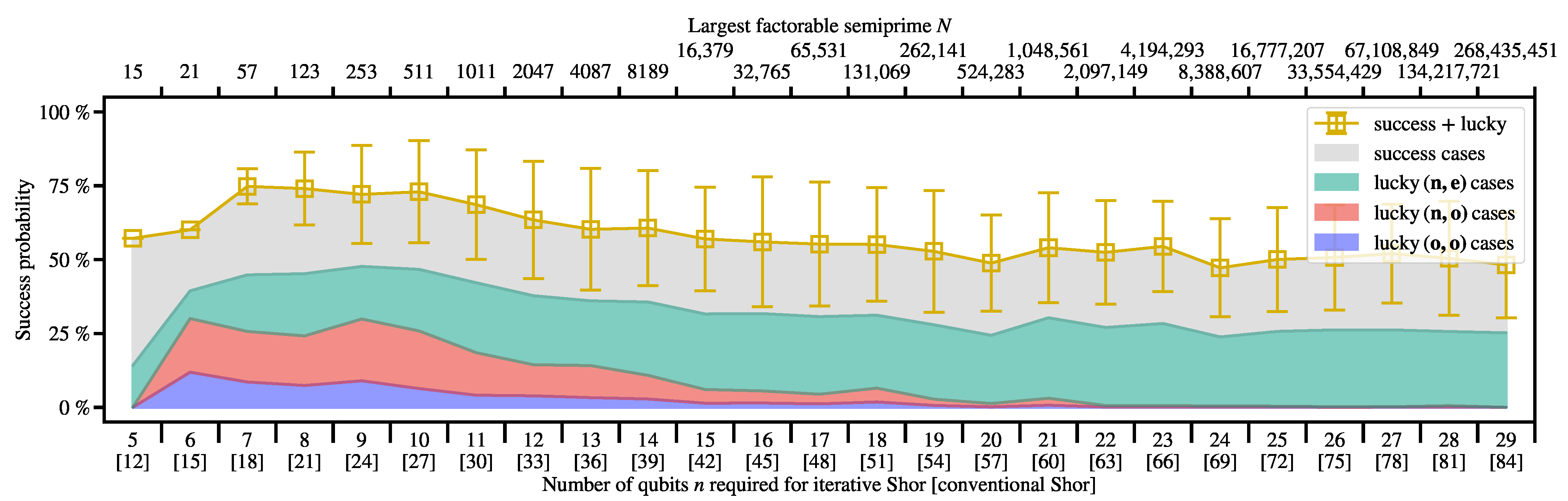
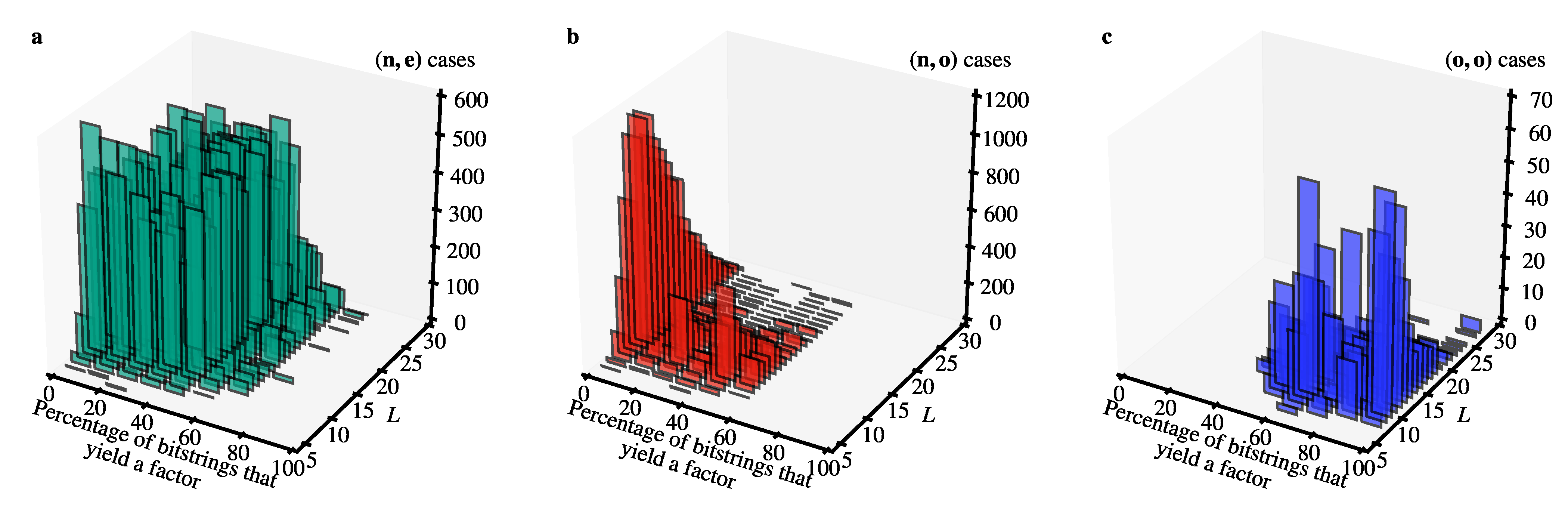
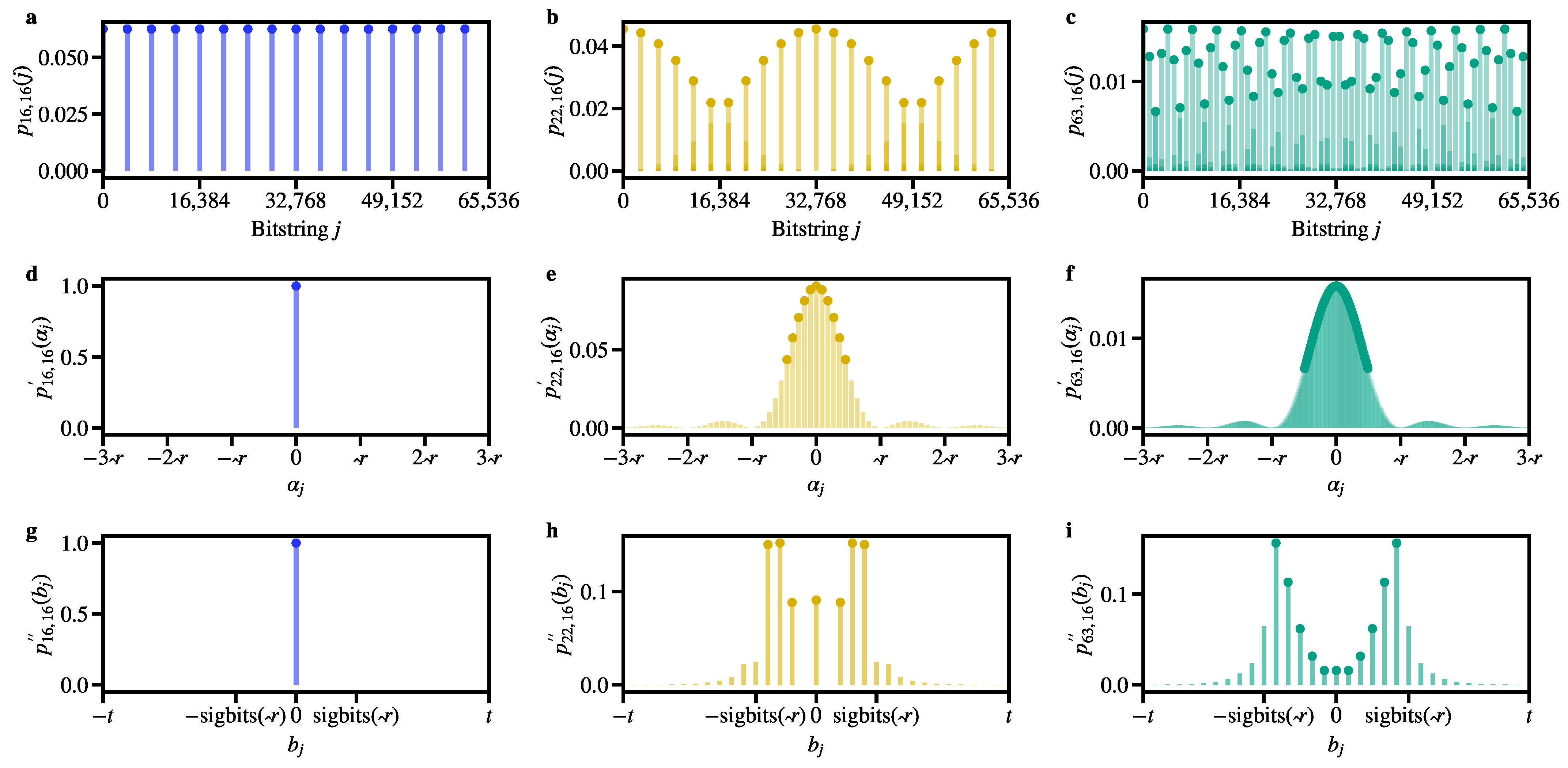
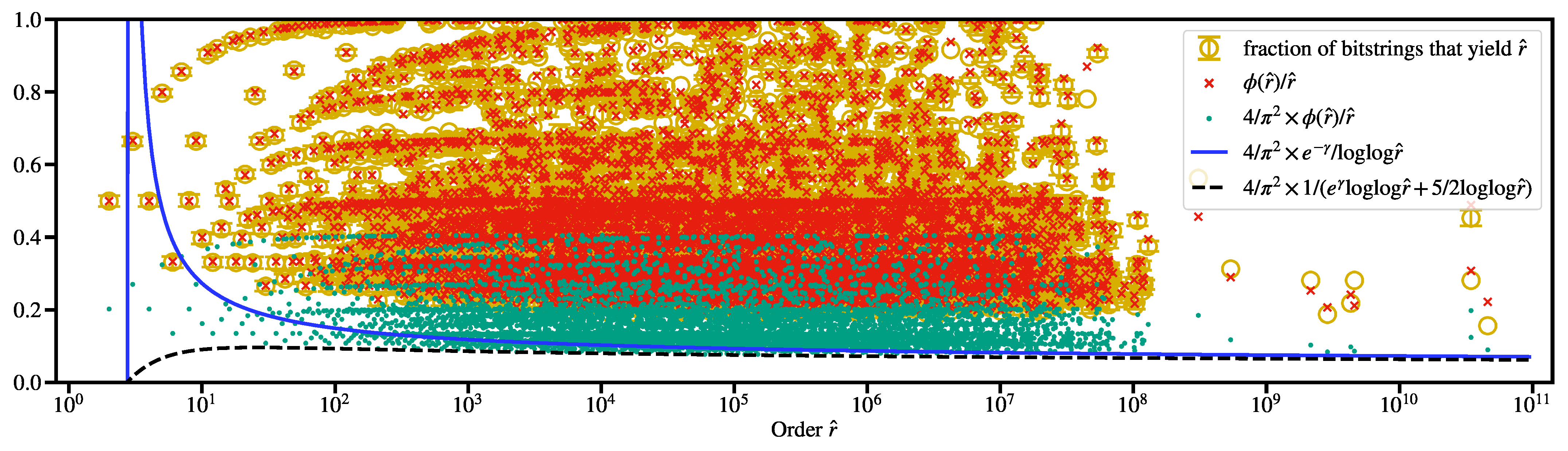
Table A1.
List of the largest interesting semiprimes (where “interesting” means that the two prime factors are distinct and have the same number of decimal digits) that can be factored using the iterative Shor algorithm for a given number of qubits , where L is the number of bits required to represent the semiprime. For each semiprime , is the recommended minimum number of classical bits to read out (cf. Figure 2).
| Qubits n | Semiprime N | Factor p | Factor q | t |
|---|---|---|---|---|
| 5 | 15 | 3 | 5 | 8 |
| 6 | 21 | 3 | 7 | 9 |
| 7 | 35 | 5 | 7 | 11 |
| 8 | 35 | 5 | 7 | 11 |
| 9 | 253 | 11 | 23 | 16 |
| 10 | 493 | 17 | 29 | 18 |
| 11 | 1007 | 19 | 53 | 20 |
| 12 | 2047 | 23 | 89 | 22 |
| 13 | 4087 | 61 | 67 | 24 |
| 14 | 8051 | 83 | 97 | 26 |
| 15 | 16,241 | 109 | 149 | 28 |
| 16 | 32,743 | 137 | 239 | 30 |
| 17 | 65,509 | 109 | 601 | 32 |
| 18 | 131,029 | 283 | 463 | 34 |
| 19 | 262,099 | 349 | 751 | 36 |
| 20 | 524,137 | 557 | 941 | 38 |
| 21 | 1,048,351 | 1009 | 1039 | 40 |
| 22 | 2,097,101 | 1399 | 1499 | 42 |
| 23 | 4,194,163 | 1307 | 3209 | 44 |
| 24 | 8,388,563 | 2357 | 3559 | 46 |
| 25 | 16,777,207 | 4093 | 4099 | 48 |
| 26 | 33,554,089 | 3797 | 8837 | 50 |
| 27 | 67,108,147 | 8011 | 8377 | 52 |
| 28 | 134,217,449 | 11,119 | 12,071 | 54 |
| 29 | 268,435,247 | 12,589 | 21,323 | 56 |
| 30 | 536,870,861 | 22,717 | 23,633 | 58 |
| 31 | 1,073,741,687 | 27,779 | 38,653 | 60 |
| 32 | 2,147,483,551 | 32,063 | 66,977 | 62 |
| 33 | 4,294,967,213 | 57,139 | 75,167 | 64 |
| 34 | 8,589,933,181 | 89,597 | 95,873 | 66 |
| 35 | 17,179,869,131 | 125,627 | 136,753 | 68 |
| 36 | 34,359,737,977 | 117,517 | 292,381 | 70 |
| 37 | 68,719,476,733 | 242,819 | 283,007 | 72 |
| 38 | 137,438,953,319 | 189,853 | 723,923 | 74 |
| 39 | 274,877,906,893 | 364,303 | 754,531 | 76 |
| 40 | 549,755,813,701 | 712,321 | 771,781 | 78 |
| 41 | 1,099,511,623,591 | 1,002,817 | 1,096,423 | 80 |
| 42 | 2,199,023,255,179 | 1,286,533 | 1,709,263 | 82 |
| 43 | 4,398,046,510,399 | 2,014,013 | 2,183,723 | 84 |
| 44 | 8,796,093,021,439 | 2,217,443 | 3,966,773 | 86 |
| 45 | 17,592,186,044,353 | 2,005,519 | 8,771,887 | 88 |
| 46 | 35,184,372,088,787 | 3,769,453 | 9,334,079 | 90 |
| 47 | 70,368,744,177,439 | 8,388,593 | 8,388,623 | 92 |
| 48 | 140,737,488,355,141 | 11,150,957 | 12,621,113 | 94 |
| 49 | 281,474,976,708,763 | 15,847,327 | 17,761,669 | 96 |
| 50 | 562,949,953,421,083 | 16,619,039 | 33,873,797 | 98 |
References
- Bressoud, D.M. Factorization and Primality Testing; Springer: New York, NY, USA, 1989. [Google Scholar] [CrossRef]
- Lehman, R.S. Factoring large integers. Math. Comput. 1974, 28, 637–646. [Google Scholar] [CrossRef]
- Lenstra, A.K.; Lenstra, H.W. The Development of the Number Field Sieve; Lecture Notes in Mathematics; Springer: Berlin/Heidelberg, Germany, 1993. [Google Scholar] [CrossRef]
- Boudot, F.; Gaudry, P.; Guillevic, A.; Heninger, N.; Thomé, E.; Zimmermann, P. Comparing the Difficulty of Factorization and Discrete Logarithm: A 240-Digit Experiment. In Proceedings of the Advances in Cryptology—CRYPTO 2020, Virtual, 17–21 August 2020; Micciancio, D., Ristenpart, T., Eds.; Springer: Cham, Switzerland, 2020; pp. 62–91. [Google Scholar] [CrossRef]
- Kleinjung, T.; Aoki, K.; Franke, J.; Lenstra, A.K.; Thomé, E.; Bos, J.W.; Gaudry, P.; Kruppa, A.; Montgomery, P.L.; Osvik, D.A.; et al. Factorization of a 768-Bit RSA Modulus. In Proceedings of the Advances in Cryptology—CRYPTO 2010, Santa Barbara, CA, USA, 15–19 August 2010; Rabin, T., Ed.; Springer: Berlin/Heidelberg, Germany, 2010; pp. 333–350. [Google Scholar] [CrossRef]
- Gidney, C.; Ekerå, M. How to factor 2048 bit RSA integers in 8 hours using 20 million noisy qubits. Quantum 2021, 5, 433. [Google Scholar] [CrossRef]
- Biasse, J.F.; Bonnetain, X.; Kirshanova, E.; Schrottenloher, A.; Song, F. Quantum algorithms for attacking hardness assumptions in classical and post-quantum cryptography. IET Inf. Secur. 2023, 17, 171–209. [Google Scholar] [CrossRef]
- Shor, P.W. Algorithms for quantum computation: Discrete logarithms and factoring. In Proceedings of the 35th Annual Symposium on Foundations of Computer Science, Santa Fe, NM, USA, 20–22 November 1994; pp. 124–134. [Google Scholar] [CrossRef]
- Ekert, A.; Jozsa, R. Quantum computation and Shor’s factoring algorithm. Rev. Mod. Phys. 1996, 68, 733–753. [Google Scholar] [CrossRef]
- Shor, P.W. Polynomial-Time Algorithms for Prime Factorization and Discrete Logarithms on a Quantum Computer. SIAM J. Comput. 1997, 26, 1484–1509. [Google Scholar] [CrossRef]
- Van Meter, R.; Itoh, K.M. Fast quantum modular exponentiation. Phys. Rev. A 2005, 71, 052320. [Google Scholar] [CrossRef]
- Kitaev, A.Y. Quantum measurements and the Abelian Stabilizer Problem. arXiv 1995, arXiv:quant-ph/9511026. [Google Scholar]
- Griffiths, R.B.; Niu, C.S. Semiclassical Fourier Transform for Quantum Computation. Phys. Rev. Lett. 1996, 76, 3228–3231. [Google Scholar] [CrossRef]
- Parker, S.; Plenio, M.B. Efficient Factorization with a Single Pure Qubit and logN Mixed Qubits. Phys. Rev. Lett. 2000, 85, 3049–3052. [Google Scholar] [CrossRef]
- Martín-López, E.; Laing, A.; Lawson, T.; Alvarez, R.; Zhou, X.Q.; O’Brien, J.L. Experimental realization of Shor’s quantum factoring algorithm using qubit recycling. Nat. Photonics 2012, 6, 773–776. [Google Scholar] [CrossRef]
- Córcoles, A.D.; Takita, M.; Inoue, K.; Lekuch, S.; Minev, Z.K.; Chow, J.M.; Gambetta, J.M. Exploiting Dynamic Quantum Circuits in a Quantum Algorithm with Superconducting Qubits. Phys. Rev. Lett. 2021, 127, 100501. [Google Scholar] [CrossRef] [PubMed]
- Peng, X.; Liao, Z.; Xu, N.; Qin, G.; Zhou, X.; Suter, D.; Du, J. Quantum Adiabatic Algorithm for Factorization and Its Experimental Implementation. Phys. Rev. Lett. 2008, 101, 220405. [Google Scholar] [CrossRef] [PubMed]
- Hegade, N.N.; Paul, K.; Albarrán-Arriagada, F.; Chen, X.; Solano, E. Digitized adiabatic quantum factorization. Phys. Rev. A 2021, 104, L050403. [Google Scholar] [CrossRef]
- Monz, T.; Nigg, D.; Martinez, E.A.; Brandl, M.F.; Schindler, P.; Rines, R.; Wang, S.X.; Chuang, I.L.; Blatt, R. Realization of a scalable Shor algorithm. Science 2016, 351, 1068–1070. [Google Scholar] [CrossRef] [PubMed]
- Amico, M.; Saleem, Z.H.; Kumph, M. Experimental study of Shor’s factoring algorithm using the IBM Q Experience. Phys. Rev. A 2019, 100, 012305. [Google Scholar] [CrossRef]
- Smolin, J.A.; Smith, G.; Vargo, A. Oversimplifying quantum factoring. Nature 2013, 499, 163–165. [Google Scholar] [CrossRef]
- Gouzien, E.; Sangouard, N. Factoring 2048-bit RSA Integers in 177 Days with 13 436 Qubits and a Multimode Memory. Phys. Rev. Lett. 2021, 127, 140503. [Google Scholar] [CrossRef]
- shorgpu: Simulation of Shor’s Algorithm with the Semiclassical Fourier Transform Using Multiple GPUs and MPI. Available online: https://jugit.fz-juelich.de/qip/shorgpu.git (accessed on 18 September 2023).
- De Raedt, K.; Michielsen, K.; De Raedt, H.; Trieu, B.; Arnold, G.; Richter, M.; Lippert, T.; Watanabe, H.; Ito, N. Massively parallel quantum computer simulator. Comput. Phys. Commun. 2007, 176, 121. [Google Scholar] [CrossRef]
- De Raedt, H.; Jin, F.; Willsch, D.; Willsch, M.; Yoshioka, N.; Ito, N.; Yuan, S.; Michielsen, K. Massively parallel quantum computer simulator, eleven years later. Comput. Phys. Commun. 2019, 237, 47–61. [Google Scholar] [CrossRef]
- Tankasala, A.; Ilatikhameneh, H. Quantum-Kit: Simulating Shor’s Factorization of 24-Bit Number on Desktop. arXiv 2020, arXiv:1908.07187. [Google Scholar]
- Wang, D.S.; Hill, C.D.; Hollenberg, L.C.L. Simulations of Shor’s algorithm using matrix product states. Quantum Inf. Process. 2017, 16, 176. [Google Scholar] [CrossRef]
- Dang, A.; Hill, C.D.; Hollenberg, L.C.L. Optimising Matrix Product State Simulations of Shor’s Algorithm. Quantum 2019, 3, 116. [Google Scholar] [CrossRef]
- Dumitrescu, E. Tree tensor network approach to simulating Shor’s algorithm. Phys. Rev. A 2017, 96, 062322. [Google Scholar] [CrossRef]
- Zhao, Y.Q.; Li, R.G.; Jiang, J.Z.; Li, C.; Li, H.Z.; Wang, E.D.; Gong, W.F.; Zhang, X.; Wei, Z.Q. Simulation of quantum computing on classical supercomputers with tensor-network edge cutting. Phys. Rev. A 2021, 104, 032603. [Google Scholar] [CrossRef]
- Ekerå, M. Qunundrum. 2020. Available online: https://github.com/ekera/qunundrum.git (accessed on 18 September 2023).
- Nielsen, M.A.; Chuang, I.L. Quantum Computation and Quantum Information: 10th Anniversary Edition; Cambridge University Press: New York, NY, USA, 2010. [Google Scholar] [CrossRef]
- Ekerå, M. On completely factoring any integer efficiently in a single run of an order-finding algorithm. Quantum Inf. Process. 2021, 20, 205. [Google Scholar] [CrossRef]
- Ekerå, M. On the success probability of quantum order finding. arXiv 2022, arXiv:2201.07791v2. [Google Scholar]
- Arute, F.; Arya, K.; Babbush, R.; Bacon, D.; Bardin, J.C.; Barends, R.; Biswas, R.; Boixo, S.; Brandao, F.G.S.L.; Buell, D.A.; et al. Quantum supremacy using a programmable superconducting processor. Nature 2019, 574, 505–510. [Google Scholar] [CrossRef] [PubMed]
- Rønnow, T.F.; Wang, Z.; Job, J.; Boixo, S.; Isakov, S.V.; Wecker, D.; Martinis, J.M.; Lidar, D.A.; Troyer, M. Defining and detecting quantum speedup. Science 2014, 345, 420–424. [Google Scholar] [CrossRef]
- Knill, E. On Shor’s Quantum Factor Finding Algorithm: Increasing the Probability of Success and Tradeoffs Involving the Fourier Transform Modulus; Tech. Rep. LAUR-95-3350; Los Alamos National Laboratory: Santa Fe, NM, USA, 1995. [Google Scholar]
- DiVincenzo, D.P. Quantum Computation. Science 1995, 270, 255–261. [Google Scholar] [CrossRef]
- Barenco, A.; Ekert, A.; Suominen, K.A.; Törmä, P. Approximate quantum Fourier transform and decoherence. Phys. Rev. A 1996, 54, 139–146. [Google Scholar] [CrossRef]
- Vedral, V.; Barenco, A.; Ekert, A. Quantum networks for elementary arithmetic operations. Phys. Rev. A 1996, 54, 147–153. [Google Scholar] [CrossRef]
- Seifert, J.P. Using Fewer Qubits in Shor’s Factorization Algorithm via Simultaneous Diophantine Approximation. In Proceedings of the Topics in Cryptology—CT-RSA 2001, San Francisco, CA, USA, 8–12 April 2001; Naccache, D., Ed.; Springer: Berlin/Heidelberg, Germany, 2001; pp. 319–327. [Google Scholar] [CrossRef]
- McAnally, D. A Refinement of Shor’s Algorithm. arXiv 2001, arXiv:quant-ph/0112055. [Google Scholar]
- Leander, G. Improving the Success Probability for Shor’s Factoring Algorithm. arXiv 2002, arXiv:quant-ph/0208183. [Google Scholar]
- Coppersmith, D. An approximate Fourier transform useful in quantum factoring. arXiv 2002, arXiv:quant-ph/0201067. [Google Scholar]
- Beauregard, S. Circuit for Shor’s algorithm using 2n+3 qubits. Quantum Inf. Comput. 2003, 3, 175. [Google Scholar] [CrossRef]
- Fowler, A.G.; Hollenberg, L.C.L. Scalability of Shor’s algorithm with a limited set of rotation gates. Phys. Rev. A 2004, 70, 032329. [Google Scholar] [CrossRef]
- Kendon, V.M.; Munro, W.J. Entanglement and its Role in Shor’s Algorithm. Quantum Inf. Comput. 2006, 6, 630. [Google Scholar] [CrossRef]
- Gerjuoy, E. Shor’s factoring algorithm and modern cryptography. An illustration of the capabilities inherent in quantum computers. Am. J. Phys 2005, 73, 521–540. [Google Scholar] [CrossRef]
- Devitt, S.J.; Fowler, A.G.; Hollenberg, L.C.L. Robustness of Shor’s algorithm. Quantum Inf. Comput. 2006, 6, 616–629. [Google Scholar] [CrossRef]
- Zalka, C. Shor’s algorithm with fewer (pure) qubits. arXiv 2016, arXiv:quant-ph/0601097. [Google Scholar]
- Bourdon, P.S.; Williams, H.T. Sharp Probability Estimates for Shor’s Order-Finding Algorithm. Quantum Inf. Comput. 2007, 7, 522–550. [Google Scholar]
- Markov, I.L.; Saeedi, M. Constant-optimized quantum circuits for modular multiplication and exponentiation. Quantum Inf. Comput. 2012, 12, 0361. [Google Scholar] [CrossRef]
- Markov, I.L.; Saeedi, M. Faster quantum number factoring via circuit synthesis. Phys. Rev. A 2013, 87, 012310. [Google Scholar] [CrossRef]
- Grosshans, F.; Lawson, T.; Morain, F.; Smith, B. Factoring Safe Semiprimes with a Single Quantum Query. arXiv 2015, arXiv:1511.04385. [Google Scholar]
- Lawson, T. Odd orders in Shor’s factoring algorithm. Quantum Inf. Process. 2015, 14, 831–838. [Google Scholar] [CrossRef]
- Johnston, A. Shor’s Algorithm and Factoring: Don’t Throw Away the Odd Orders. Cryptology ePrint Archive, Report 2017/083. 2017. Available online: https://ia.cr/2017/083 (accessed on 18 September 2023).
- Häner, T.; Roetteler, M.; Svore, K.M. Factoring using 2n+2 qubits with Toffoli based modular multiplication. Quantum Inf. Comput. 2017, 17, 0673. [Google Scholar] [CrossRef]
- Davis, E.D. Benchmarks for quantum computers from Shor’s algorithm. arXiv 2021, arXiv:2111.13856. [Google Scholar]
- Bastos, D.C.; Brasil Kowada, L.A. How to detect whether Shor’s algorithm succeeds against large integers without a quantum computer. Procedia Comput. Sci. 2021, 195, 145–151. [Google Scholar] [CrossRef]
- Antipov, A.V.; Kiktenko, E.O.; Fedorov, A.K. Efficient realization of quantum primitives for Shor’s algorithm using PennyLane library. PLoS ONE 2022, 17, e0271462. [Google Scholar] [CrossRef] [PubMed]
- Nam, Y.S.; Blümel, R. Performance scaling of Shor’s algorithm with a banded quantum Fourier transform. Phys. Rev. A 2012, 86, 044303. [Google Scholar] [CrossRef]
- Ekerå, M. Quantum algorithms for computing general discrete logarithms and orders with tradeoffs. J. Math. Cryptol. 2021, 15, 359–407. [Google Scholar] [CrossRef]
- Ekerå, M.; Håstad, J. Quantum Algorithms for Computing Short Discrete Logarithms and Factoring RSA Integers. In Proceedings of the Post-Quantum Cryptography, Utrecht, The Netherlands, 26–28 June 2017; Lange, T., Takagi, T., Eds.; Springer: Cham, Switzerland, 2017; pp. 347–363. [Google Scholar] [CrossRef]
- Ekerå, M. On post-processing in the quantum algorithm for computing short discrete logarithms. Des. Codes Cryptogr. 2020, 88, 2313–2335. [Google Scholar] [CrossRef]
- Jozsa, R. Quantum factoring, discrete logarithms, and the hidden subgroup problem. Comput. Sci. Eng. 2001, 3, 34–43. [Google Scholar] [CrossRef]
- Hardy, G.H.; Wright, E.M. An Introduction to the Theory of Numbers, 6th ed.; Oxford University Press: Oxford, UK, 2008. [Google Scholar]
- Bernstein, D.J.; Biasse, J.F.; Mosca, M. A Low-Resource Quantum Factoring Algorithm. In Proceedings of the Post-Quantum Cryptography, Utrecht, The Netherlands, 26–28 June 2017; Lange, T., Takagi, T., Eds.; Springer: Cham, Switzerland, 2017; pp. 330–346. [Google Scholar] [CrossRef]
- Grover, L.K. A Fast Quantum Mechanical Algorithm for Database Search. In Proceedings of the Twenty-Eighth Annual ACM Symposium on Theory of Computing, Philadelphia, PA, USA, 22–24 May 1996; pp. 212–219. [Google Scholar] [CrossRef]
- Li, J.; Peng, X.; Du, J.; Suter, D. An Efficient Exact Quantum Algorithm for the Integer Square-free Decomposition Problem. Sci. Rep. 2012, 2, 1–5. [Google Scholar] [CrossRef]
- Vandersypen, L.M.K.; Steffen, M.; Breyta, G.; Yannoni, C.S.; Sherwood, M.H.; Chuang, I.L. Experimental realization of Shor’s quantum factoring algorithm using nuclear magnetic resonance. Nature 2001, 414, 883–887. [Google Scholar] [CrossRef] [PubMed]
- Lu, C.Y.; Browne, D.E.; Yang, T.; Pan, J.W. Demonstration of a Compiled Version of Shor’s Quantum Factoring Algorithm Using Photonic Qubits. Phys. Rev. Lett. 2007, 99, 250504. [Google Scholar] [CrossRef] [PubMed]
- Lanyon, B.P.; Weinhold, T.J.; Langford, N.K.; Barbieri, M.; James, D.F.V.; Gilchrist, A.; White, A.G. Experimental Demonstration of a Compiled Version of Shor’s Algorithm with Quantum Entanglement. Phys. Rev. Lett. 2007, 99, 250505. [Google Scholar] [CrossRef]
- Politi, A.; Matthews, J.C.F.; O’Brien, J.L. Shor’s Quantum Factoring Algorithm on a Photonic Chip. Science 2009, 325, 1221. [Google Scholar] [CrossRef] [PubMed]
- Lucero, E.; Barends, R.; Chen, Y.; Kelly, J.; Mariantoni, M.; Megrant, A.; O’Malley, P.; Sank, D.; Vainsencher, A.; Wenner, J.; et al. Computing prime factors with a Josephson phase qubit quantum processor. Nat. Phys. 2012, 8, 719–723. [Google Scholar] [CrossRef]
- Skosana, U.; Tame, M. Demonstration of Shor’s factoring algorithm for N = 21 on IBM quantum processors. Sci. Rep. 2021, 11, 16599. [Google Scholar] [CrossRef]
- Abhijith, J.; Adedoyin, A.; Ambrosiano, J.; Anisimov, P.; Casper, W.; Chennupati, G.; Coffrin, C.; Djidjev, H.; Gunter, D.; Karra, S.; et al. Quantum Algorithm & Implementations for Beginners. ACM Trans. Quantum Comput. 2022, 3, 18. [Google Scholar] [CrossRef]
- Andriyash, E.; Bian, Z.; Chudak, F.; Drew-Brook, M.; King, A.D.; Macready, W.G.; Roy, A. Boosting Integer Factoring Performance via Quantum Annealing Offsets; Technical Report; D-Wave Technical Report Series 14-1002A-B; D-Wave Systems Inc.: Burnaby, BC, Canada, 2016. [Google Scholar]
- Dridi, R.; Alghassi, H. Prime factorization using quantum annealing and computational algebraic geometry. Sci. Rep. 2017, 7, 43048. [Google Scholar] [CrossRef]
- Jiang, S.; Britt, K.A.; McCaskey, A.J.; Humble, T.S.; Kais, S. Quantum Annealing for Prime Factorization. Sci. Rep. 2018, 8, 17667. [Google Scholar] [CrossRef] [PubMed]
- Peng, W.; Wang, B.; Hu, F.; Wang, Y.; Fang, X.; Chen, X.; Wang, C. Factoring larger integers with fewer qubits via quantum annealing with optimized parameters. Sci. China Phys. Mech. Astron. 2019, 62, 60311. [Google Scholar] [CrossRef]
- Mengoni, R.; Ottaviani, D.; Iorio, P. Breaking RSA Security With A Low Noise D-Wave 2000Q Quantum Annealer: Computational Times, Limitations And Prospects. arXiv 2020, arXiv:2005.02268. [Google Scholar]
- Wang, B.; Hu, F.; Yao, H.; Wang, C. Prime factorization algorithm based on parameter optimization of Ising model. Sci. Rep. 2020, 10, 7106. [Google Scholar] [CrossRef]
- King, A.D.; Suzuki, S.; Raymond, J.; Zucca, A.; Lanting, T.; Altomare, F.; Berkley, A.J.; Ejtemaee, S.; Hoskinson, E.; Huang, S.; et al. Coherent quantum annealing in a programmable 2,000qubit Ising chain. Nat. Phys. 2022, 18, 1324–1328. [Google Scholar] [CrossRef]
- King, A.D.; Raymond, J.; Lanting, T.; Harris, R.; Zucca, A.; Altomare, F.; Berkley, A.J.; Boothby, K.; Ejtemaee, S.; Enderud, C.; et al. Quantum critical dynamics in a 5,000-qubit programmable spin glass. Nature 2023, 617, 61–66. [Google Scholar] [CrossRef] [PubMed]
- Message Passing Interface Forum. MPI: A Message-Passing Interface Standard Version 4.0, 2021.
- Willsch, D.; Willsch, M.; Jin, F.; Michielsen, K.; De Raedt, H. GPU-accelerated simulations of quantum annealing and the quantum approximate optimization algorithm. Comput. Phys. Commun. 2022, 278, 108411. [Google Scholar] [CrossRef]
- Michielsen, K.; Nocon, M.; Willsch, D.; Jin, F.; Lippert, T.; De Raedt, H. Benchmarking gate-based quantum computers. Comput. Phys. Commun. 2017, 220, 44–55. [Google Scholar] [CrossRef]
- Weiss, U. Quantum Dissipative Systems, 4th ed.; World Scientific: Singapore, 2012. [Google Scholar] [CrossRef]
- Paladino, E.; Galperin, Y.M.; Falci, G.; Altshuler, B.L. 1/f noise: Implications for solid-state quantum information. Rev. Mod. Phys. 2014, 86, 361–418. [Google Scholar] [CrossRef]
- Carroll, M.; Rosenblatt, S.; Jurcevic, P.; Lauer, I.; Kandala, A. Dynamics of superconducting qubit relaxation times. NPJ Quantum Inf. 2022, 8, 132. [Google Scholar] [CrossRef]
- Fox, M. Quantum Optics: An Introduction; Oxford Master Series in Physics; Oxford University Press: Oxford, UK, 2006. [Google Scholar]
- Wallraff, A.; Schuster, D.I.; Blais, A.; Frunzio, L.; Majer, J.; Devoret, M.H.; Girvin, S.M.; Schoelkopf, R.J. Approaching Unit Visibility for Control of a Superconducting Qubit with Dispersive Readout. Phys. Rev. Lett. 2005, 95, 060501. [Google Scholar] [CrossRef] [PubMed]
- Gambetta, J.; Blais, A.; Schuster, D.I.; Wallraff, A.; Frunzio, L.; Majer, J.; Devoret, M.H.; Girvin, S.M.; Schoelkopf, R.J. Qubit-photon interactions in a cavity: Measurement-induced dephasing and number splitting. Phys. Rev. A 2006, 74, 042318. [Google Scholar] [CrossRef]
- Reed, M.D.; DiCarlo, L.; Johnson, B.R.; Sun, L.; Schuster, D.I.; Frunzio, L.; Schoelkopf, R.J. High-Fidelity Readout in Circuit Quantum Electrodynamics Using the Jaynes-Cummings Nonlinearity. Phys. Rev. Lett. 2010, 105, 173601. [Google Scholar] [CrossRef]
- Jacobs, K. Quantum Measurement Theory and Its Applications; Cambridge University Press: Cambridge, MA, USA, 2014. [Google Scholar] [CrossRef]
- Naghiloo, M. Introduction to Experimental Quantum Measurement with Superconducting Qubits. arXiv 2019, arXiv:1904.09291. [Google Scholar]
- Boissonneault, M.; Gambetta, J.M.; Blais, A. Improved Superconducting Qubit Readout by Qubit-Induced Nonlinearities. Phys. Rev. Lett. 2010, 105, 100504. [Google Scholar] [CrossRef]
- Holevo, A.S. Quantum Systems, Channels, Information: A Mathematical Introduction; De Gruyter: Berlin, Germany, 2019. [Google Scholar] [CrossRef]
- Wilde, M.M. Quantum Information Theory; Cambridge University Press: Cambridge, UK, 2017. [Google Scholar] [CrossRef]
- Jülich Supercomputing Centre. JUWELS: Modular Tier-0/1 Supercomputer at the Jülich Supercomputing Centre. J. Large-Scale Res. Facil. 2019, 5, A135. [Google Scholar] [CrossRef]
- Jülich Supercomputing Centre. JUWELS Cluster and Booster: Exascale Pathfinder with Modular Supercomputing Architecture at Juelich Supercomputing Centre. J. Large-Scale Res. Facil. 2021, 7, A138. [Google Scholar] [CrossRef]
- NVIDIA A100 Tensor Core GPU. Data Sheet. 2022. Available online: https://www.nvidia.com/content/dam/en-zz/Solutions/Data-Center/a100/pdf/nvidia-a100-datasheet-nvidia-us-2188504-web.pdf (accessed on 18 September 2023).
- Miller, G.L. Riemann’s hypothesis and tests for primality. J. Comput. Syst. Sci 1976, 13, 300–317. [Google Scholar] [CrossRef]
- Michielsen, K.; De Raedt, K.; De Raedt, H. Simulation of Quantum Computation: A Deterministic Event-Based Approach. J. Comput. Theor. Nanosci. 2005, 2, 227–239. [Google Scholar] [CrossRef]
- Ekerå, M. Quppy. 2023. To Appear. Available online: https://github.com/ekera/quppy.git (accessed on 6 October 2023).
- Google Quantum AI. Exponential suppression of bit or phase errors with cyclic error correction. Nature 2021, 595, 383–387. [Google Scholar] [CrossRef]
- Krinner, S.; Lacroix, N.; Remm, A.; Di Paolo, A.; Genois, E.; Leroux, C.; Hellings, C.; Lazar, S.; Swiadek, F.; Herrmann, J.; et al. Realizing repeated quantum error correction in a distance-three surface code. Nature 2022, 605, 669–674. [Google Scholar] [CrossRef] [PubMed]
- Sivak, V.V.; Eickbusch, A.; Royer, B.; Singh, S.; Tsioutsios, I.; Ganjam, S.; Miano, A.; Brock, B.L.; Ding, A.Z.; Frunzio, L.; et al. Real-time quantum error correction beyond break-even. Nature 2023, 616, 50–55. [Google Scholar] [CrossRef] [PubMed]
- Einarsson, G. Probability Analysis of a Quantum Computer. arXiv 2003, arXiv:quant-ph/0303074. [Google Scholar]
- Press, W.H.; Teukolsky, S.A.; Vetterling, W.T.; Flannery, B.P. Numerical Recipes 3rd Edition: The Art of Scientific Computing; Cambridge University Press: New York, NY, USA, 2007. [Google Scholar]
- Jaynes, E.T.; Bretthorst, G.L. Probability Theory: The Logic of Science; Cambridge University Press: Cambridge, MA, USA, 2003. [Google Scholar] [CrossRef]
- Nicolas, J.L. Petites valeurs de la fonction d’Euler. J. Number Theory 1983, 17, 375–388. [Google Scholar] [CrossRef]
- Rosser, J.B.; Schoenfeld, L. Approximate formulas for some functions of prime numbers. Illinois J. Math. 1962, 6, 64. [Google Scholar] [CrossRef]
- Nielsen, M.A. Errata List for “Quantum Computation and Quantum Information”. 2014. Available online: https://michaelnielsen.org/qcqi/errata/errata/errata.html (accessed on 18 September 2023).
- Carmichael, R.D. Note on a new number theory function. Bull. Am. Math. Soc. 1910, 16, 232–238. [Google Scholar] [CrossRef]
Figure 1.
Scheme to test Shor’s algorithm. After selecting an L-bit semiprime to factor and a random integer coprime to N (blue), a quantum computer or quantum computer simulator with qubits runs the iterative Shor algorithm (red) and produces several bitstrings j with t bits (green). Here, “iterative” means that one qubit is measured and reused t times to produce the t classical bits of each j. Every bitstring j is analyzed using either Shor’s [8,9,10,32] or Ekerå’s [33,34] post-processing method (yellow), independent of whether certain algorithmic requirements on j are satisfied or not. Here, k (r) denotes the numerator (denominator) obtained from a continued fraction expansion of . Note that the expression for the factors in the yellow section is specific to Shor’s post-processing; for Ekerå’s post-processing, has to be replaced by , where is a random element of and is usually a multiple of the largest odd divisor of r (see below). We remark that conceptually, it does not matter whether the green section is performed by a quantum computer simulator or a real quantum computing device.

Figure 2.
Quantum circuit of the iterative Shor algorithm. The circuit consists of qubits that undergo t separate stages , in which the classical bit is measured. Each stage starts with the first qubit in the initial state and ends with this qubit being measured (middle row). Between initialization and measurement, each stage consists of a controlled modular multiplication (bottom row) with some power of a (see Equation (6)), then a rotation gate controlled by all previously measured classical bits (see Equation (8)), and finally a Hadamard gate. The resulting bit is used to assemble the classical bitstring (top row).

Figure 3.
Illustration of the MPI communication scheme for the implementation of the controlled modular multiplication gate given by Equation (6) for the quantum circuit to factor with . This circuit needs qubits, i.e., the first qubit for the measurement (middle line in Figure 2) and qubits to represent N. There are GPUs in this example, so we have global and local qubits (note that this is only for illustration purposes; in practice one would use much fewer GPUs for 7 qubits). Shown is the implementation of the last oracle gate in Figure 2 (the controlled modular multiplication with ) from the perspective of GPU#11. denotes, in the notation of Equation (1), the statevector coefficient . Red arrows represent coefficients that are sent from GPU#11 to another GPU (whose index is computed from ). Blue arrows represent coefficients that are sent to GPU#11 from another GPU (whose index is computed from ). Purple arrows represent coefficients that stay on GPU#11. Note that GPU#15 is not involved in the communication because for all of GPU#15, so the oracle gate does not permute these coefficients (the last case in Equation (6)).

Figure 4.
Success probabilities for Shor’s factoring algorithm. For each factoring problem , the success probabilities are given by the ratio of all M bitstrings (sampled from Shor’s algorithm) that yield a factor. If a bitstring satisfies all conditions of Shor’s (original) algorithm, it is counted as “success” (green circles). If the bitstring yields a factor, even if these conditions are not met, it is counted as “success + lucky” (yellow squares). (a) Individual success probabilities for each of the 61,362 factoring problems . The markers are placed at the positions of the factored semiprime according to the top axis. The number of qubits required using both the iterative and the conventional Shor algorithm is indicated on the bottom axis. (b) Average success probabilities for the 52,077 uniform factoring problems, averaged over all problems for a given number of qubits n (see text). Error bars indicate the root-mean-square deviations of the averages of a across different semiprimes N for the same n. Blue triangles represent the success probabilities for all factoring problems that can be solved after a bitstring has yielded the order of a modulo N (which always happened within the first 33 bitstrings, see Figure 5b). The red line represents the theoretical bound for Shor’s post-processing, given by (see Appendix A.2). Lines are guides to the eye.

Figure 5.
Statistical analysis of how often Shor’s algorithm has to be executed to solve a factoring problem. Shown is the number of bitstrings that had to be generated until (a), a factor of N, or (b), the order of a modulo N could be found. The main plots show the statistics extracted from all 52,077 uniformly distributed factoring problems , for which the total number of sampled bitstrings is . Insets show the same information (on a logarithmic scale) for subsets of 2500 problems that all require the same number of qubits and for the iterative Shor algorithm (corresponding to and for the conventional Shor algorithm, respectively).

Figure 6.
Success probabilities of Shor’s algorithm when less than the recommended classical bits are extracted from the QFT. Every bar represents the fraction of 1 million sampled bitstrings classified as “success” (green), “lucky” (yellow), and “fail” (blue). The factored semiprime is N = 15,707 (such that ) with (a) , (b) , and (c) . The corresponding orders of a modulo N are indicated at the top. Increasing t beyond 28 does not further improve the success probabilities.

Figure 7.
Breakdown of the average success probabilities for successful factoring scenarios. The contributions to the average “success + lucky” probability (yellow squares) from Figure 4b are divided into the “success” cases (gray), the lucky (n,e) cases (green), the lucky (n,o) cases (red), and the lucky (o,o) cases (blue). Note that an L-bit semiprime requires qubits for the iterative Shor algorithm and roughly qubits using the conventional Shor algorithm, as indicated on the bottom axis. The largest odd semiprime that can be factored with a given number of qubits is shown on the top axis. Lines are guides to the eye.

Figure 8.
Classification of the different “lucky” scenarios. Shown is the absolute number of (a) (n,e) cases, (b) (n,o) cases, and (c) (o,o) cases, which yield a factor even though the sufficient conditions for Shor’s algorithm are not met. For each bit length , the total number of cases is given by 2500 uniformly distributed factoring problems (for smaller L, the total number is smaller than 2500 because all possibilities for factoring problems are exhausted, see Appendix B). Every bar represents a -wide half-open interval with for the percentage of all bitstrings that yield a factor in this case. For instance, the large leftmost red bar at and in panel (b) means that in 1197 out of 2500 cases, up to of all sampled bitstrings yield a factor even though they represent an (n,o) case, i.e., they produce an odd number r that is not the order. Similarly, the large rightmost blue bar at in panel (c) means that in 68 out of 2500 cases, more than of all sampled bitstrings yield a factor even though the correctly extracted order is odd.

Figure 9.
Histograms of the fractions between the order and the denominator r extracted from the continued fractions algorithm. Shown is the percentage of bitstrings for (normalized by all “lucky” bitstrings) that yield a factor in the (a) (n,e) and (b) (n,o) scenario, respectively. Here, r is not the order but often a large divisor of it. Additionally, the bars at the very left for represent the number of cases where the extracted r is actually larger than the order , which may occasionally happen when a bitstring j is sampled at a non-zero probability that is not a peak (cf. Figure A1b,c).

Figure 10.
Classification of “lucky” factorizations for the case that the extracted integer r is odd, using instead of . Shown is the percentage of bitstrings that yield a factor as a function of the smallest prime factor of the semiprime . (a) The lucky (n,o) probabilities, classified in terms of the minimum order of a modulo p and q (see legend; prioritized from top to bottom). (b) The lucky (o,o) probabilities, fully classified in terms of the cases where and is odd (blue crosses) and the rest (green pluses). In both (a) and (b), annotations indicate an additional condition that is satisfied by many (but not all) cases at this percentage level ( denotes an odd integer). We use the notation to denote the order of a modulo p, i.e., the smallest integer m such that .

Figure 11.
Performance of Shor’s algorithm using Ekerå’s post-processing in the presence of errors. (a) Success probability using Ekerå’s post-processing with for the largest scenarios from Figure 4a in the case of classical measurement errors with (blue squares), quantum measurement errors with (yellow circles), amplitude initialization errors with (green upward-pointing triangles), phase initialization errors with (red downward-pointing triangles), bit flip errors (purple stars) with , or no errors (gray diamonds). Additionally, the solid gray line shows the bound Equation (43) for semiprimes with prime factors, and the vertical dashed gray lines show by how much the bound underestimates the actual performance (cf. [34]). (b) Success probability as a function of the effective single-qubit error probability for the 30-qubit case N = 536,870,903 from panel (a). The black dash-dotted line represents the success probability in the case of independent destructive errors, . The inset shows schematically in which parts of the quantum circuit in Figure 2 each of the different errors happen.

Disclaimer/Publisher’s Note: The statements, opinions and data contained in all publications are solely those of the individual author(s) and contributor(s) and not of MDPI and/or the editor(s). MDPI and/or the editor(s) disclaim responsibility for any injury to people or property resulting from any ideas, methods, instructions or products referred to in the content. |
© 2023 by the authors. Licensee MDPI, Basel, Switzerland. This article is an open access article distributed under the terms and conditions of the Creative Commons Attribution (CC BY) license (https://creativecommons.org/licenses/by/4.0/).
Share and Cite
MDPI and ACS Style
Willsch, D.; Willsch, M.; Jin, F.; De Raedt, H.; Michielsen, K. Large-Scale Simulation of Shor’s Quantum Factoring Algorithm. Mathematics 2023, 11, 4222. https://doi.org/10.3390/math11194222
AMA Style
Willsch D, Willsch M, Jin F, De Raedt H, Michielsen K. Large-Scale Simulation of Shor’s Quantum Factoring Algorithm. Mathematics. 2023; 11(19):4222. https://doi.org/10.3390/math11194222
Chicago/Turabian StyleWillsch, Dennis, Madita Willsch, Fengping Jin, Hans De Raedt, and Kristel Michielsen. 2023. "Large-Scale Simulation of Shor’s Quantum Factoring Algorithm" Mathematics 11, no. 19: 4222. https://doi.org/10.3390/math11194222
Note that from the first issue of 2016, this journal uses article numbers instead of page numbers. See further details here.