

Temperature-Controlled Laser Cutting of an Electrical Steel Sheet Using a Novel Fuzzy Logic Controller


1
Faculty of Mechanical Engineering, Can Tho University of Technology, Ninh Kieu District, Can Tho City 10000, Vietnam
2
Department of Mechanical Engineering, National Central University, Jhong-Li District, Tao-Yuan City 32001, Taiwan
*
Author to whom correspondence should be addressed.
Mathematics 2023, 11(23), 4769; https://doi.org/10.3390/math11234769
Submission received: 26 October 2023
/
Revised: 18 November 2023
/
Accepted: 24 November 2023
/
Published: 25 November 2023
(This article belongs to the Special Issue Advances in Control Systems and Automatic Control)
Abstract
:A novel PID-type fuzzy logic controller (FLC) with an online fuzzy tuner was created to maintain stable in situ control of the cutting front temperature, aiming to enhance the laser process for thin non-oriented electrical steel sheets. In the developed controller, the output scaling factors and the universe of discourse were initially optimized using a hybrid of the particle swarm optimization and grey wolf optimization methods. The optimal parameters obtained were utilized in experiments involving the laser cutting of thin non-oriented electrical steel sheets, compared to an open-loop control system maintaining a constant cutting speed. The PID-type FLC with an online fuzzy tuner demonstrated a superior cutting quality, generating a smaller roundness and a reduced heat-affected zone (HAZ) through the in situ tuning of control parameters. Particularly, the HAZ width was significantly smaller than that reported in a previous study which used fuzzy gain scheduling for temperature control. Moreover, the cutting time was diminished by optimally adjusting the cutting speed using PID-type FLC with an online fuzzy tuner. Therefore, the accumulated heat in the steel sheet, particularly under high laser pulse frequencies, was effectively reduced, making it suitable for industrial applications.
Keywords:
laser cutting; electrical steel; PID-type fuzzy logic controller; temperature control; heat affected zone; roundnessMSC:
93-051. Introduction
The cores of electric motors and generators are typically produced by shaping non-oriented electrical steel (silicon steel) laminations through cutting to meet the specified requirements. In the production of a core using non-oriented electrical steel sheets, manufacturing techniques such as shearing and punching may be employed; however, these methods can introduce stress near the cutting edge [1]. A stator or rotor of electrical machinery generally consists of thin silicon steel sheets with a thickness from 0.1 mm to 1 mm. This kind of part is ordinarily stamped in high quantities. Stamping is highly repeatable in mass production, but not very precise. Stamping is primarily hindered by the cost of fixtures and tools [2]. As a result, stamping could be much more expensive for low-volume or rapid prototyping. In comparison to mechanical cutting and stamping, laser cutting provides a greater flexibility and precision, making it easier to design cores for electrical machinery. Furthermore, the plastic and elastic stresses induced by mechanical cutting could cause the magnetic properties of electrical steel to deteriorate [3] and negatively affect the efficiency of the core [4,5,6]. When mechanical forming is undertaken at the cutting edge, deformation at the cutting edge may adversely affect the core performance in electrical machinery [7,8]. Magnetic field and flux density in electrical steels seem to be adversely affected by residual stress [9,10].
Laser cutting is a non-contact technique and it does not generate remarkable shear deformation [11]. However, a heat-affected zone (HAZ) and residual stress may be induced by thermal effects in the laser cutting of electrical steel. The high levels of heat energy generally elevate the temperature at the cutting edge, resulting in a HAZ [12], which is affected by the laser cutting speed [13]. A relationship between the laser cutting speed and the cutting front temperature was obtained by Grum and Zuljan [14]. It was found that a constant heat flux per unit time at the cutting front is ideal for high-quality cutting [14]. Any change in the cutting front temperature would affect the HAZ and geometrical precision of kerf cut [15]. Hence, if the cutting speed is optimally adjusted in situ by controlling the temperature at the cutting front area, it is possible to enhance the cutting quality of thin electrical steel sheets.
Some studies have used the conventional proportional-integral-derivative (PID) control technique to control the temperature or size of the melt pool measured via pyrometers or cameras in real time [16,17,18]. In those studies [16,17,18], the laser cladding process was governed using constant PID parameters, with a particular focus on monitoring feedback parameters such as melt pool shape, melt pool temperature, and cladding height to enable real-time adjustments to the process parameters. Moreover, an improved closed-loop controller was developed in our earlier study to precisely control the working temperature during the laser cutting of non-oriented electrical steel sheets [19]. It was found that a better quality of finer and uniform kerf width, a smaller HAZ, and a lesser amount of dross attachment were produced by such an improved real-time closed-loop control [19]. However, that closed-loop system was applied in laser cutting a straight slit [19]. In addition, those studies [16,17,18,19] focused on the closed-loop control of temperature through the adjustment of laser power in laser cladding and laser cutting. There is a deficiency in research concerning the closed-loop control of temperature through the adjustment of cutting speed in the laser cutting of non-oriented electrical steels to reduce the HAZ width and improve the roundness in a circular cut.
To improve the control performance against a system of high non-linearity, fuzzy logic control approaches have been proposed [20,21,22,23]. However, as the fuzzy controller behaves like a PD controller, its output has a static error (steady-state error) [24]. Several studies have proposed eliminating static error using PID in combination with a fuzzy control algorithm [25,26,27,28], which is called a PID-type fuzzy logic controller (FLC). To avoid a change in the ambient environment that may randomly influence the process parameters, some studies have proposed self-tuning PID-type FLCs which use three types of tuning mechanisms to adjust the scaling factors, namely a fuzzy tuner [29,30,31], function tuner [32], and relative rate observer (RRO) [33]. In particular, the tuning mechanism of a fuzzy tuner is more efficient, since only one scaling factor is tuned and it is more robust, as reported in our earlier study [31]. In this regard, it is aimed to give an improved control performance by applying a self-tuning scheme into the PID-type FLC to enable better cutting speed control for the laser cutting of thin electrical steel sheets.
This study is an extension of our earlier studies [19,31] and aims to develop an advanced system to precisely control the cutting front temperature and optimize the cutting speed in laser cutting circular paths on electrical steel sheets. In this system, a pyrometer was used to measure the temperature at the cutting front of the workpiece and the cutting speed was adjusted in situ using a PID-type FLC with online fuzzy tuner. Experiments on the laser cutting of thin electrical steel sheets were performed using an open-loop controller with a constant power and the proposed PID-type FLC with an online fuzzy tuner to compare the cutting quality. The results of this study hopefully could provide a solution to the needs of precise circular cuts on electrical steel sheets in manufacturing electric motors and generators.
2. Experiment Procedure
Experimental Setup
A schematic diagram of the experimental setup is shown in Figure 1. A 20 W ytterbium pulsed fiber laser (YLP-1-100-20, IPG Photonics Co., Marlborough, MA, USA) with a wavelength of 1064 nm was used for all the laser cutting experiments. The laser spot focused on the working surface was approximately 50 μm in diameter. The laser system was equipped with a linear moving stage (X, Y) for cutting the workpiece under a given cutting speed. The laser head and the scanner were attached to a linear drive (Z). To cut through the electrical steel sheets in a single run, initial trial tests were conducted to identify the suitable processing parameters, such as the laser power, cutting speed, and pulsed frequency. Utilizing the findings from the trial tests, the laser cutting process parameters leading to an enhanced cutting quality were selected and are detailed in Table 1 for the upcoming experiments. The given thin electrical steel sheets were cut without the use of shielding/assisted gas.
As shown in Figure 1, the temperature at the cutting front on the workpiece was measured using a pyrometer (IMPAC IN 210, LumaSense Technologies Inc., Ballerup, Denmark). A data acquisition module (DAQ USB-4711A, Advantech Co., Ltd., Taipei, Taiwan) was used to record the output data from the pyrometer. The data acquisition module contained a LabVIEW platform that included the developed PID-type FLC with an online fuzzy tuner and generated the control signal to the moving stage controller for the cutting speed adjustment.
A schematic diagram of the specimen size and circular cutting path is shown in Figure 2. The thin electrical steel sheets, with dimensions 120 mm × 40 mm × 0.1 mm, were shear cut from a roll of strip (ST-100, Nikkin Denji Kogyyo Co., Ltd., Saitama, Japan). To prevent measuring the laser-focused molten area with temperature variation, the temperature at a point 3 mm ahead of the laser spot on the sample was measured by the pyrometer, as shown in Figure 2b. The focus diameter of the pyrometer on the sample was 2.5 mm. Note that the cutting speed range was selected to produce an improved cutting quality in a single-run cutting in range from 0.1 mm/s to 0.7 mm/s. Therefore, the pyrometer had a focal spot size of 2.5 mm in diameter with minimal response time of 120 ms, which is appropriate and satisfactory. Table 1 lists the process parameters for the circular cut. In both open-loop and closed-loop control modes, all parameters except cutting speed were kept constant. After cutting, the geometrical measurement of kerf was taken around the cutting path on each sample using a coordinate measuring machine (Leitz PMM12106, Hexagon AB, Sweden). To characterize the HAZ morphology, the samples after cutting were immersed in a 10% Nital solution for 60 s [34]. A 3D laser scanning confocal microscope (VK-X1000, Keyence Co., Osaka, Japan) was used to observe the HAZ region following such etching.
3. Closed-Loop Control System
3.1. System Identification
In order to optimize the functionality of the PID-type FLC, a mathematical model of the laser cutting process was developed. The procedure of determining the relevant parameters, in a calculation of the required transfer function of the laser cutting system, includes generating different speeds of the moving stage (Figure 3a) and recording the cutting front temperature (Figure 3b) in terms of voltage in a single run. The process of parameter identification requires persistent excitation in which the input is large enough to excite all the identifier modes. Since a triangular wave of 0.02 Hz is composed of a series of sine and cosine waves with various frequencies, it was used as the system input of the speed to satisfy the condition of persistent excitation [35], as shown in Figure 3a. Note that, in the identification procedure, the input speed and the output temperature were recorded simultaneously by DAQ. The lower and upper values of the input speed were set as 1 V and 5 V, respectively. The recorded data were then used as an input of the MATLAB identification toolbox. As shown in Figure 3b, the waveforms of the experiment and the transfer function were generally in good agreement. As a consequence, the transfer function was acquired using the MATLAB® code (The MathWorks Inc., Natick, MA, USA), and is given below,
3.2. PID-Type FLC Structure with an Online Fuzzy Tuner
The block diagram of the self-tuning PID-type FLC using the online fuzzy tuner developed in this study is shown in Figure 4. Its structure was basically similar to that in our earlier work and the details of such self-tuning PID-type FLC can be found in Ref. [31]. The user-specified set-point temperature (Tsp) was compared to the measured temperature (Tm). Tm was calculated by applying a low pass filter on the raw temperature data from the pyrometer. The resulting error, e, was the difference between Tsp and Tm, which is an input to the PID-type FLC implemented in the LabVIEW code.
Figure 4 shows the PID-type FLC with two output scaling factors, namely α and β. Additionally, its input membership functions were also adjustable through two parameters (T1 and T2), as shown in Figure 5 [31]. The membership functions for scaled error E and scaled derivative of error were triangular functions. Five linguistic levels were assigned to the fuzzy sets for E and such as negative big (NB), negative small (NS), zero (ZO), positive small (PS), and positive big (PB). Thirteen singleton membership functions were used for the output variable U of FLC, as shown in Figure 6 [31]. The fuzzy rules for the computation of U were shown in our previous study [31]. In general, the fuzzy rules of FLC used in Ref. [31] were adopted, but the values of α, β, T1, and T2 were reconfigured to achieve the optimal performance in the laser cutting of thin non-oriented electrical steel sheets. To avoid changes in the ambient environment, the system needs to be tuned in an online manner to obtain the optimal control performance. It is feasible to choose an appropriate value for β to obtain a fast system response while avoiding instability [31]. To implement this idea, a fuzzy tuning mechanism was introduced to tune the gain β in a way similar to that in Ref. [31]. In the fuzzy tuner, three parameters (T3, T4, and T5) were re-designed to optimize the performance of the tuning mechanism, as shown in Figure 7.
As shown in Figure 7, the utilization of s-shaped, z-shaped, and triangular membership functions for both the error e and its derivative is depicted, which are adjustable through two parameters T3 and T4, respectively, and for the output γ within the range from −T5 to T5. Negative (N), zero (Z), and positive (P) linguistic levels were assigned to the fuzzy sets for the input variables (e and ). For the output variables γ, there were three linguistic levels, namely small (S), zero (ZO), and big (B). In practical applications, a fuzzy system’s performance is greatly influenced by membership functions. To achieve a desired response, initially, rectilinear membership functions (e.g., trapezoidal and triangular) were used, and subsequently, they were substituted with curvilinear ones (e.g., s-shaped and z-shaped) in the fuzzy tuner.
Using the fuzzy tuner rules outlined in Table 2, γ was computed through the adaptive updating equation provided below,
where γinitial represents the initial value of γ and Δγ denotes the tuned value derived from the fuzzy tuning mechanism, falling within the range from −T5 to T5. A small value is chosen for Δγ when the error is very large, and vice versa. γ was found as a non-negative value by applying the fuzzy rules in Table 2. As a result, the control performance was enhanced.
3.3. Optimization Technique
Various metaheuristic optimization algorithms have been introduced in recent years and shown promising results in the optimization of multidimensional mathematical problems. In our earlier study [31], it was found that a hybrid optimization approach of particle swarm optimization and grey wolf optimization (PSO-GWO) algorithms exhibited a superior performance to that of PSO or GWO alone. In this study, there are seven parameters, namely α, β, T1, T2, T3, T4, and T5, that need to be optimized using the hybrid PSO-GWO. A detailed procedure of the hybrid PSO-GWO algorithm was given in Refs. [31,36].
4. Results and Discussion
4.1. Optimization Technique
The PID-type FLC with an online fuzzy tuner was simulated on MATLAB® for the given laser cutting system to find the optimal parameters. Seven optimum parameters, α, β, T1, T2, T3, T4, and T5, were found in the simulation using the hybrid PSO-GWO algorithm. The simulation was employed with a sampling period T = 0.01 s. The hybrid PSO-GWO algorithm was executed with a population size of 50 sets, and the maximum number of iterations was established at 60. For the evaluation and minimization of errors, the fitness function in this study was the integral time absolute error (ITAE), given below:
where is the error magnitude of the controller input. The transfer function given in Equation (1) was used in the simulation. The optimization process reached the smallest fitness value within 57 iterations. The worst fitness was 0.69019, which took place at the first iteration. The hybrid PSO-GWO approach reached the lowest (best) fitness value of 0.06565 at the 57th iteration. The optimum values of the seven parameters were found as α = 1.56, β = 52.24, T1 = 57.31, T2 = 100, T3 = 100, T4 = 88.85, and T5 = 90.89. These parameters were then employed in the PID-type FLC with an online fuzzy tuner for the real-time control of the laser cutting system. Note that, in the experiments, the PID-type FLC with an online fuzzy tuner was implemented in the DAQ using the LabVIEW code.
4.2. Temperature Variation in Open Loop Control and PID-Type FLC with Online Fuzzy Tuner
As shown in Figure 3, the output temperature at the cutting front increased sharply with the input cutting speed. Consequently, the highest temperature of cutting front accompanied the strongest brightness and vice versa, as shown in Figure 3b. It was found that, the higher temperature an object exhibits, the stronger brightness it radiates, according to the Stefan–Boltzmann law [37]. As the cutting front is radiated directly by laser, it shows a higher temperature and greater brightness when increasing the cutting speed [37]. The spraying shape, direction, brightness, and quality of cutting front all vary with cutting speed. In particular, the cutting front shows a weak brightness at a low cutting speed and vice versa in case of a high speed [37]. Therefore, cutting speed has a great influence on the cutting quality. Generally, there are two types of cutting quality, namely over-burning defect regions at low speeds and dross defect regions at high speeds [37]. To overcome this difference, the closed-loop control approach was applied in this study to adjust the speed continuously in real time so that the cutting speed remained at the optimal one.
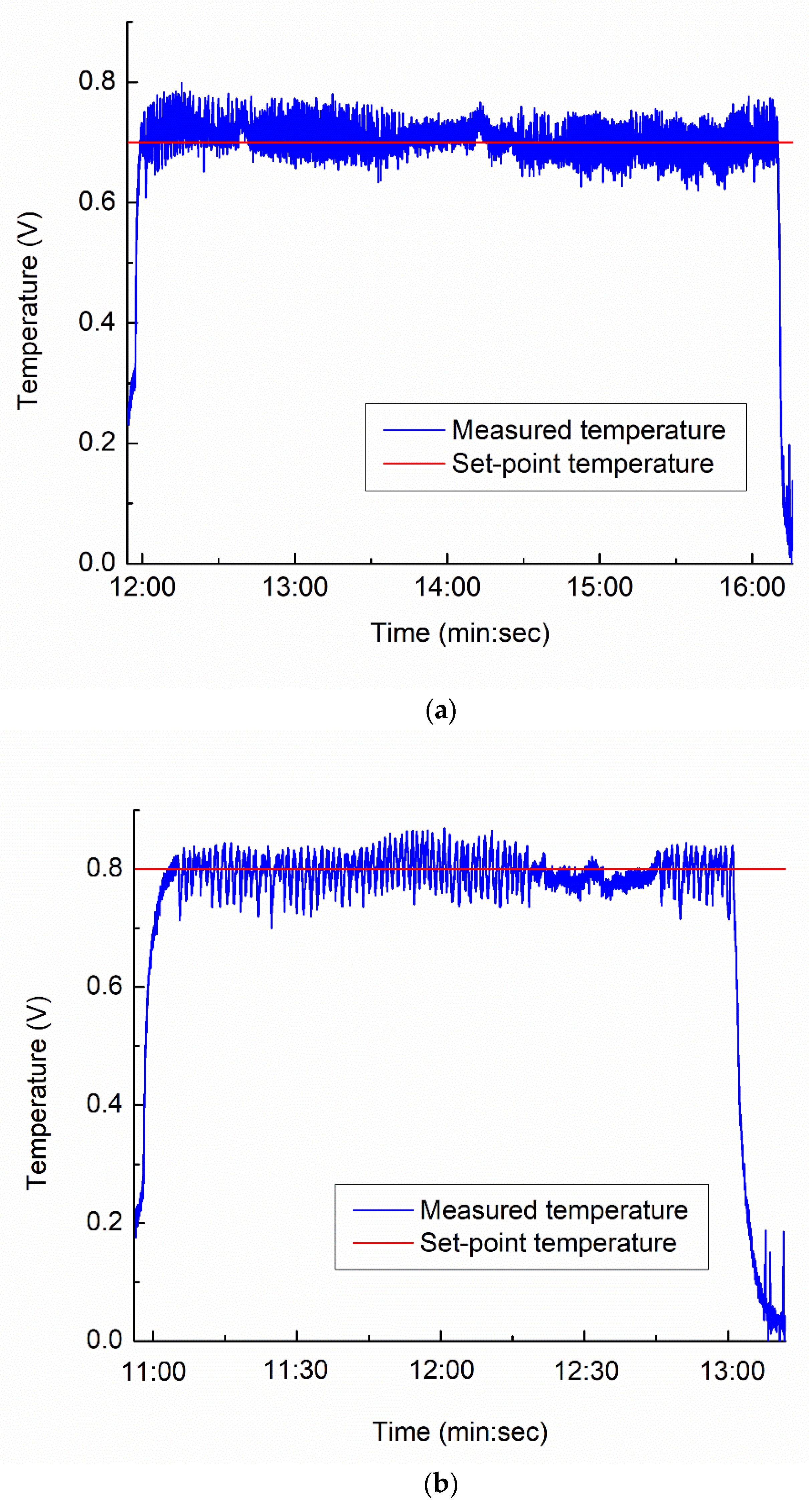
Given two selected set-point temperatures, 0.7 V and 0.8 V, the designed PID-type FLC with a fuzzy tuner was used to cut a circular path on the non-oriented electrical steel sheets. These two set-point temperatures were selected for generating the average HAZ less than 150 μm. As shown in Figure 8, the results clearly indicated that the PID-type FLC with online fuzzy tuner developed in this study achieved a more stable state than that in the open-loop control with a constant speed of 0.5 mm/s at a laser pulse frequency of 20 kHz. As shown in Figure 8a,b, the closed-loop system operated efficiently with the set-points at 0.7 V and 0.8 V, given a low pulse frequency of 20 kHz. In addition, the selected fuzzy rules and seven optimal parameters in the PID-type FLC with an online fuzzy tuner were proven to be effective for the targeted laser cutting process. In contrast, for the open-loop control with a constant cutting speed, the cutting front temperature varied significantly along the cutting path, as shown in Figure 8c. Such variation is expected to produce inconsistent cutting quality. It is thus demonstrated that real-time temperature control using the PID-type FLC with an online fuzzy tuner is better suited for laser cutting of thin non-oriented electrical steel sheets.
4.3. Roundness Variation in Open-Loop Control and PID-Type FLC with Online Fuzzy Tuner
The roundness of the circular cut was determined by calculating the variance between the largest and smallest diameters. For each sample, 12 positions were selected for measuring the diameter. Note that, in the experiment, two repeated tests were conducted for each, given cutting speed from 0.1 mm/s to 0.5 mm/s under the open-loop control with a laser pulse frequency of 20 kHz or 40 kHz. For the PID-type FLC with an online fuzzy tuner, three repeated tests were conducted for each given set-point at laser pulse frequencies of 20 kHz and 40 kHz.
Figure 9 shows the roundness measurements of various cutting speeds under open-loop control at laser pulse frequencies of 20 kHz and 40 kHz. As shown in Figure 9a, the roundness generally increased with a cutting speed from 0.1 mm/s to 0.5 mm/s, given a low pulse frequency of 20 kHz. At a low pulse frequency and a low cutting speed, the laser spots overlapped to a greater extent, such that the patterned shape was more uniformly cut. In addition, by increasing the cutting speed, heat conduction energy loss was reduced, resulting in a wider solidified dross [38]. This led to a larger roundness for a high cutting speed. Moreover, the molten material might not be easily ejected out from the cut kerf as no shielding/assisted gas was provided. Thus, the dross area became larger for a high cutting speed, leading to an increase in roundness [39]. On the other hand, the roundness reflected the influences of the cutting speed on the kerf waviness [34]. As the cutting speed was increased, the kerf waviness became larger. Thus, an increase in cutting speed led to an increase in roundness [34].
The relationship between roundness and cutting speed at a pulse frequency of 40 kHz is shown in Figure 9b. Pulses of 40 kHz produce a larger roundness at a high cutting speed compared to hose at 20 kHz. This is due to laser irradiation with a high pulse frequency having less cooling time between pulses, generating a cutting edge with a wider solidified dross than that at a low pulse frequency [38,40]. In addition, the dross deposition area became wider as the pulse frequency and cutting speed increased, as reported in the Ref. [39]. In contrast, the PID-type FLC with an online fuzzy tuner produced a controlled temperature at the cutting front of the workpiece, such that the roundness was significantly reduced and much smaller than that of both open-loop control cases, as listed in Table 3.
In addition, the average cutting speed in the closed-loop control was calculated as the ratio of the circumference of the circular cut over the cutting time. In this way, the average cutting speed was in the range of 0.30–0.35 mm/s and 0.41–0.48 mm/s for 0.7 V and 0.8 V at 20 kHz, respectively. As shown in Figure 9a and Table 3, it indicates that a larger roundness existed in the open-loop control samples than the closed-loop control samples. In particular, the roundness of the closed-loop control samples of 0.7 V and 0.8 V was even much smaller than that of the open-loop control samples under a constant cutting speed of 0.1 mm/s and above, given a laser pulse frequency of 20 kHz. Similarly, open-loop control generated a significantly greater roundness than closed-loop control did at a higher pulse frequency of 40 kHz, as shown in Figure 9b and Table 3. At the pulse frequency of 40 kHz, the average cutting speed under closed-loop control was 0.25–0.38 mm/s and 0.46–0.55 mm/s for 0.7 V and 0.8 V, respectively. Again, for a given laser pulse frequency of 40 kHz, the roundness of the closed-loop control was comparable with that of cutting speed of 0.1 mm/s and was much smaller than that of a cutting speed of 0.2 mm/s and above in the open-loop control. Apparently, using the closed-loop control approach can achieve a shorter cutting time and a smaller roundness on the given non-oriented electrical steel sheets even at a higher pulse frequency of 40 kHz. As the cutting front temperature was controlled under the closed-loop control by adjusting the cutting speed, a better balanced heat conduction in the electrical steel sheet was obtained. Consequently, it can reduce the amount of molten material and solidified dross in case of a high cutting speed and high pulse frequency of 40 kHz, resulting in a smaller roundness.
4.4. HAZ Variation in Open-Loop Control and PID-Type FLC with Online Fuzzy Tuner
The HAZ of each sample was observed at 20 selected positions along the circumference with an equal interval, using a 3D laser scanning confocal microscope. The representative HAZ profiles of the samples cut under open-loop control with a constant cutting speed from 0.1 to 0.5 mm/s at 20 kHz are shown in Figure 10. In our earlier work [34], the authors outlined a strategy for identifying the HAZ in thin non-oriented electrical steel sheets cut by a laser beam. Note that the yellow dash lines in Figure 10 outline the HAZ at the cutting edge. The observed HAZ width was in the range of 41–45 μm for 0.1 mm/s, 58–69 μm for 0.2 mm/s, 75–85 μm for 0.3 mm/s, 88–91 μm for 0.4 mm/s, and 92–95 μm for 0.5 mm/s. As demonstrated in Figure 10, a greater width of HAZ was observed when the workpiece was subjected to a higher cutting front temperature at a high cutting speed.
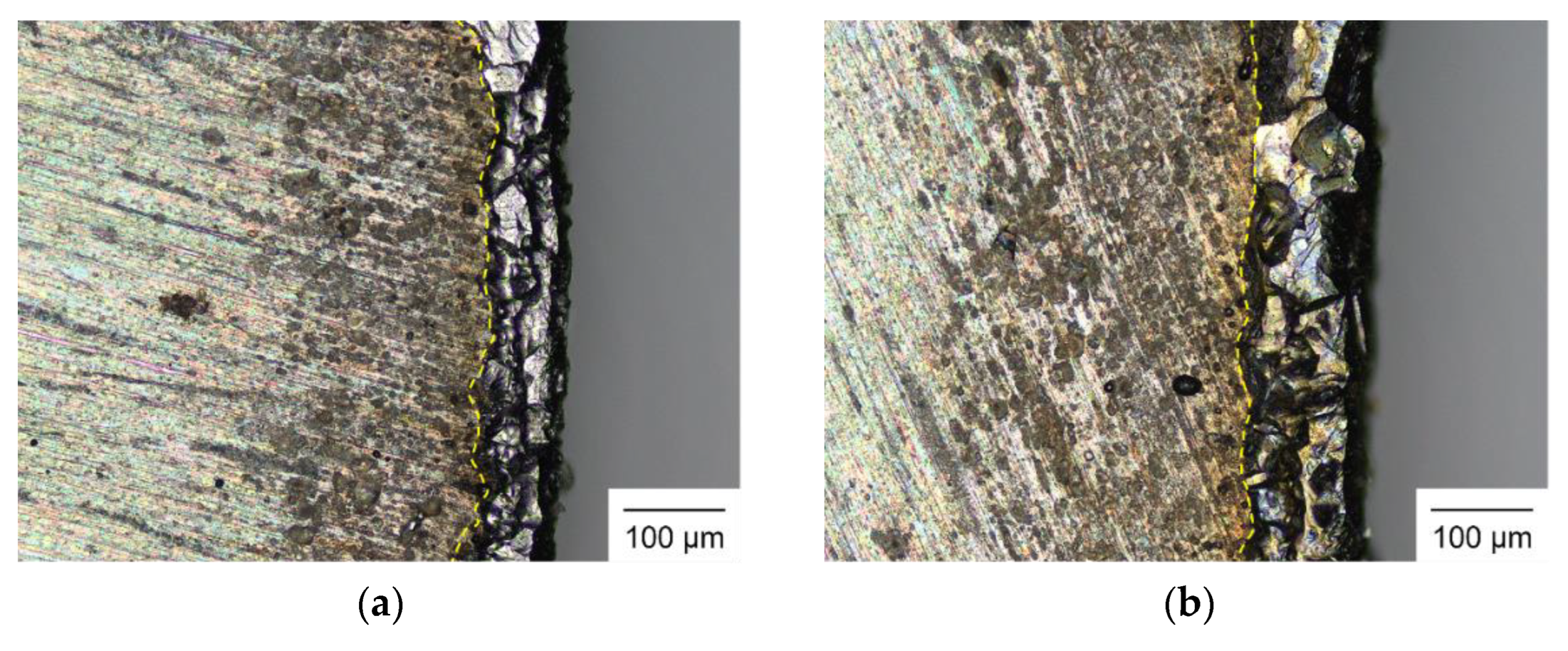
Figure 11 shows the representative HAZ profiles of the samples cut under the PID-type FLC with an online fuzzy tuner with two set-point temperatures. As depicted in Figure 11, elevating the set-point temperature from 0.7 V to 0.8 V led to an expansion in the width of the HAZ. The increase in set-point temperature needed a higher cutting speed to maintain a constant temperature at the cutting front. The typical HAZ width was in the range of 63–74 μm and 81–90 μm for 0.7 V and 0.8 V, respectively. As shown in Figure 10c–e and Figure 11, it indicates that a larger HAZ width along the cut kerf existed in the open-loop control samples than the closed-loop control samples. Note that a HAZ width of 75 μm and above was found in the open-loop control samples with a constant speed of 0.3 mm/s, which was larger than that of the closed-loop control samples of 0.7 V with an average cutting speed of 0.30–0.35 mm/s. Similarly, the HAZ width of the closed-loop control samples of 0.8 V was 81–90 μm and smaller than the counterparts of the open-loop control with constant cutting speeds of 0.4 and 0.5 mm/s. Therefore, the closed-loop control approach produced a balanced thermal energy absorbed by heat conduction at the cutting front of the thin non-oriented electrical steel sheet via an online adjustment of the cutting speed. This led to a shorter cutting time and simultaneously achieved a smaller HAZ under closed-loop control. This was because the total heat input by the laser beam was optimally adjusted in an online manner using the PID-type FLC with an online fuzzy tuner.
To align the laser cutting process with the scale and throughput requirements for industrial applications, it is typical to operate the laser at elevated pulse frequencies and a high laser power. However, heat accumulation in the steel sheet at a high pulse frequency can deteriorate the cutting quality. Figure 12 shows the representative HAZ profiles produced under open-loop control with a higher pulse frequency of 40 kHz. At a higher pulse frequency of 40 kHz, the laser behaved in a way more like a continuous wave and the cut surface hardly had enough time to cool down. Therefore, the sheet was heated to a higher temperature resulting in a larger HAZ. As shown in Figure 12, a high cutting speed was also accompanied by a larger HAZ width due to a higher cutting front temperature. The observed HAZ width was in the range of 103–109 μm for 0.1 mm/s, 114–122 μm for 0.2 mm/s, 134–137 μm for 0.3 mm/s, 155–159 μm for 0.4 mm/s, and 164–170 μm for 0.5 mm/s. In a comparison between Figure 10 and Figure 12, a much larger HAZ was observed at 40 kHz than that at 20 kHz, given a cutting speed.
Figure 13 shows the representative HAZ profiles of the samples cut under the PID-type FLC with an online fuzzy tuner at 40 kHz. As shown in Figure 13, again, an increase in the set-point temperature from 0.7 V to 0.8 V generated a greater width of HAZ. The typical HAZ width was in the range of 76–85 μm and 94–109 μm for 0.7 V and 0.8 V, respectively. The calculated average cutting speed under closed-loop control was 0.25–0.38 mm/s and 0.46–0.55 mm/s for 0.7 V and 0.8 V, respectively. As shown in Figure 12 and Figure 13, the HAZ width under open-loop control was significantly greater than that under closed-loop control. For example, for the closed-loop control with a set-point of 0.8 V, which had an average cutting speed of 0.46–0.55 mm/s, the HAZ width (94–109 μm) was even smaller than that (103–109 μm) of the lowest cutting speed (0.1 mm/s) under open-loop control. Apparently, using the closed-loop control approach could achieve a shorter cutting time and a smaller HAZ on the given non-oriented electrical steel sheet at a higher pulse frequency of 40 kHz. Additionally, for open-loop control, the HAZ at 40 kHz was significantly larger than that at 20 kHz, as described above. However, when the cutting front temperature was controlled by the PID-type FLC with an online fuzzy tuner, the difference in the HAZ width between 20 kHz and 40 kHz was reduced. Consequently, the proposed closed-loop control could reduce the effect of heat accumulation in the steel sheets at a high pulse frequency and be compatible with the scale and throughput needed for industrial use.
In comparison with our earlier study, which used fuzzy gain scheduling for temperature control through the adjustment of laser power [19], the maximum average HAZ width of a circular cut at 20 kHz (81–90 μm) and 40 kHz (94–109 μm) in this study were significantly smaller than that (208–276 μm) of the straight cut in Ref. [19]. In Ref. [19], a maximum laser power of 15.02 W, a frequency of 20 kHz, and a maximum cutting speed of 1.1 mm/s were used, while the counterparts in this study were 14.07 W, 20 kHz and 40 kHz, and 0.7 mm/s, respectively. Such a comparison indicates that the proposed advanced temperature control technique through the adjustment of cutting speed in this study proves its superiority in reducing the HAZ width and optimizing the roundness. Therefore, in the closed-loop approach using the PID-type FLC with an online fuzzy tuner, the in situ adjustment of cutting speed ensures the stable maintenance of the cutting front temperature, resulting in an enhanced cutting quality for the laser cutting of thin non-oriented electrical steel sheets.
5. Conclusions
In this investigation, a novel advanced system incorporating a PID-type FLC with an online fuzzy tuner was developed and employed for the laser cutting of thin non-oriented electrical steel sheets. It comprised a pyrometer for measuring the temperature at the cutting front and a real-time controller of PID-type FLC with an online fuzzy tuner to adjust the cutting speed in situ during the laser cutting process. The conclusions are given below.
- (1)
- A hybrid PSO-GWO algorithm was employed to find the optimal parameters of α, β, T1, T2, T3, T4, and T5 in the PID-type FLC with an online fuzzy tuner, and proved its effectiveness in the given laser cutting processes.
- (2)
- Through in the situ tuning of the control parameters, the PID-type FLC with an online fuzzy tuner outperformed the open-loop control in terms of performance and tracking responses.
- (3)
- A relation between the roundness of the cutting quality and the cutting speed was found. The roundness generally increased with the cutting speed, given a laser pulse frequency of 20 kHz or 40 kHz.
- (4)
- The PID-type FLC with an online fuzzy tuner stably maintained the controlled temperature at the cutting front of the workpiece, such that the roundness was significantly reduced and much smaller than that in the open-loop control cases.
- (5)
- The HAZ width exhibited a notable reduction during the process of pulsed laser cutting for non-oriented electrical steel sheets using the PID-type FLC with an online fuzzy tuner, as compared to the open-loop control. In comparison to a previous study using fuzzy gain scheduling for temperature control, the HAZ width produced by the PID-type FLC with an online fuzzy tuner was also much smaller.
- (6)
- The developed PID-type FLC with an online fuzzy tuner could reduce the cutting time while also achieving a smaller roundness and HAZ on the non-oriented electrical steel sheet.
Author Contributions
Conceptualization, D.-T.N. and C.-K.L.; methodology, C.-K.L., Y.-T.L., J.-R.H. and P.-C.T.; investigation, D.-T.N.; resources, C.-K.L., Y.-T.L., J.-R.H. and P.-C.T.; data curation, D.-T.N. and C.-K.L.; writing—original draft preparation, D.-T.N.; writing—review and editing, C.-K.L.; project administration, C.-K.L.; funding acquisition, P.-C.T. All authors have read and agreed to the published version of the manuscript.
Funding
This work was funded by the Ministry of Science and Technology (Taiwan) under contract numbers Nos. MOST 108-2218-E-008-019 and MOST 109-2218-E-008-003.
Institutional Review Board Statement
Not applicable.
Informed Consent Statement
Not applicable.
Data Availability Statement
Data are contained within the article.
Conflicts of Interest
The authors declare no conflict of interest. The funders had no role in the design of the study; in the collection, analyses, or interpretation of data; in the writing of the manuscript or in the decision to publish the results.
References
- Oda, Y.; Kohno, M.; Honda, A. Recent development of non-oriented electrical steel sheet for automobile electrical devices. J. Magn. Magn. Mater. 2008, 320, 2430–2435. [Google Scholar] [CrossRef]
- Brettschneider, C. High precision laser cutting of electrical steel. PhotonicsViews 2019, 16, 51–53. [Google Scholar]
- Park, J.S.; Park, J.T. Effect of Stress Relief Annealing Temperature and Atmosphere on the Microstructure and Magnetic Properties of Non-oriented Electrical Steels. In Proceedings of the 2016 6th International Electric Drives Production Conference (EDPC), Nuremberg, Germany, 30 November–1 December 2016; pp. 288–292. [Google Scholar]
- Rygal, R.; Moses, A.; Derebasi, N.; Schneider, J.; Schoppa, A. Influence of cutting stress on magnetic field and flux density distribution in non-oriented electrical steels. J. Magn. Magn. Mater. 2000, 215, 687–689. [Google Scholar] [CrossRef]
- Schoppa, A.; Schneider, J.; Wuppermann, C.D. Influence of the manufacturing process on the magnetic properties of non-oriented electrical steels. J. Magn. Magn. Mater. 2000, 215, 74–78. [Google Scholar] [CrossRef]
- Senda, K.; Ishida, M.; Nakasu, Y.; Yagi, M. Influence of shearing process on domain structure and magnetic properties of non-oriented electrical steel. J. Magn. Magn. Mater. 2006, 304, e513–e515. [Google Scholar] [CrossRef]
- Fujisaki, K.; Hirayama, R.; Kawachi, T.; Satou, S.; Kaidou, C.; Yabumoto, M.; Kubota, T. Motor core iron loss analysis evaluating shrink fitting and stamping by finite-element method. IEEE Trans. Magn. 2007, 43, 1950–1954. [Google Scholar] [CrossRef]
- Salvador, L. Influence of Cutting Process on Magnetic Properties of Electrical Steel. Master’s Thesis, Aalto University, Espoo, Finland, 2016. [Google Scholar]
- Loisos, G.; Moses, A.J. Effect of mechanical and Nd: YAG laser cutting on magnetic flux distribution near the cut edge of non-oriented steels. J. Mater. Process. Technol. 2005, 161, 151–155. [Google Scholar] [CrossRef]
- Siebert, R.; Schneider, J.; Beyer, E. Laser cutting and mechanical cutting of electrical steels and its effect on the magnetic properties. IEEE Trans. Magn. 2014, 50, 1–4. [Google Scholar] [CrossRef]
- Emura, M.; Landgraf, F.J.G.; Ross, W.; Barreta, J.R. The influence of cutting technique on the magnetic properties of electrical steels. J. Magn. Magn. Mater. 2003, 254, 358–360. [Google Scholar] [CrossRef]
- Belhadj, A.; Baudouin, P.; Breaban, F.; Deffontaine, A.; Dewulf, M.; Houbaert, Y. Effect of laser cutting on microstructure and on magnetic properties of grain non-oriented electrical steels. J. Magn. Magn. Mater. 2003, 256, 20–31. [Google Scholar] [CrossRef]
- Salem, H.G.; Mansour, M.S.; Badr, Y.; Abbas, W.A. CW Nd: YAG laser cutting of ultra low carbon steel thin sheets using O2 assist gas. J. Mater. Process. Technol. 2008, 196, 64–72. [Google Scholar] [CrossRef]
- Grum, J.; Zuljan, D. Analysis of heat effects in laser cutting of steels. J. Mater. Eng. Perform. 1996, 5, 526–537. [Google Scholar] [CrossRef]
- Di Pietro, P.; Yao, Y.L. A numerical investigation into cutting front mobility in CO2 laser cutting. Int. J. Mach. Tools Manuf. 1995, 35, 673–688. [Google Scholar] [CrossRef]
- Fathi, A.; Khajepour, A.; Toyserkani, E.; Durali, M. Clad height control in laser solid freeform fabrication using a feedforward PID controller. Int. J. Adv. Manuf. Technol. 2007, 35, 280–292. [Google Scholar] [CrossRef]
- Hofman, J.T.; Pathiraj, B.; van Dijk, J.; de Lange, D.F.; Meijer, J. A camera based feedback control strategy for the laser cladding process. J. Mater. Process. Technol. 2012, 212, 2455–2462. [Google Scholar] [CrossRef]
- Salehi, D.; Brandt, M. Melt pool temperature control using LabVIEW in Nd: YAG laser blown powder cladding process. Int. J. Adv. Manuf. Technol. 2006, 29, 273–278. [Google Scholar] [CrossRef]
- Nguyen, D.T.; Ho, J.R.; Tung, P.C.; Lin, C.K. An improved real-time temperature control for pulsed laser cutting of non-oriented electrical steel. Opt. Laser Technol. 2021, 136, 106783. [Google Scholar] [CrossRef]
- Liang, M.; Yeap, T.; Hermansyah, A.; Rahmati, S. Fuzzy control of spindle torque for industrial CNC machining. Int. J. Mach. Tools Manuf. 2003, 43, 1497–1508. [Google Scholar] [CrossRef]
- Liang, M.; Yeap, T.; Rahmati, S.; Han, Z. Fuzzy control of spindle power in end milling processes. Int. J. Mach. Tools Manuf. 2002, 42, 1487–1496. [Google Scholar] [CrossRef]
- Liao, Y.S.; Woo, J.C. Design of a fuzzy controller for the adaptive control of WEDM process. Int. J. Mach. Tools Manuf. 2000, 40, 2293–2307. [Google Scholar] [CrossRef]
- Tung, P.C.; Wang, S.R.; Lo, K. Application of self-tuning fuzzy controller for a Cartesian manipulator on unknown contours. Int. J. Mach. Tools Manuf. 2000, 40, 943–955. [Google Scholar] [CrossRef]
- Siddique, N. Intelligent Control: A Hybrid Approach Based on Fuzzy Logic, Neural Networks and Genetic Algorithms, 1st ed.; Springer: New York, NY, USA, 2014. [Google Scholar]
- Huang, X.; Shi, L. Simulation on a Fuzzy-PID Position Controller of the CNC Servo System. In Proceedings of the International Conference on Intelligent Systems Design and Applications, Jinan, China, 16–18 October 2006; pp. 305–309. [Google Scholar]
- Kha, N.B.; Anh, K.K. Position Control of Shape Memory Alloy Actuators by Using Self Tuning Fuzzy PID Controller. In Proceedings of the International Conference on Industrial Electronics and Applications, Singapore, 24–26 May 2006; pp. 1–5. [Google Scholar]
- Lee, C.D.; Chuang, C.W.; Kao, C.C. Apply Fuzzy PID Rule to PDA Based Control of Position Control of Slider Crank Mechanisms. In Proceedings of the International Conference on Cybernetics and Intelligent Systems, Singapore, 1–3 December 2004; pp. 508–513. [Google Scholar]
- Reznik, L.; Ghanayem, O.; Bourmistrov, A. PID plus fuzzy controller structures as a design base for industrial applications. Eng. Appl. Artif. Intell. 2000, 13, 419–430. [Google Scholar] [CrossRef]
- Mudi, R.K.; Pal, N.R. A robust self-tuning scheme for PI-and PD-type fuzzy controllers. IEEE Trans. Fuzzy Syst. 1999, 7, 2–16. [Google Scholar] [CrossRef]
- Chung, H.Y.; Chen, B.C.; Lin, J.J. A PI-type fuzzy controller with self-tuning scaling factors. Fuzzy Sets Syst. 1998, 93, 23–28. [Google Scholar] [CrossRef]
- Nguyen, D.T.; Ho, J.R.; Tung, P.C.; Lin, C.K. A hybrid PSO-GWO fuzzy logic controller with a new fuzzy tuner. Int. J. Fuzzy Syst. 2021, 24, 1586–1604. [Google Scholar] [CrossRef]
- Woo, Z.W.; Chung, H.Y.; Lin, J.J. A PID type fuzzy controller with self-tuning scaling factors. Fuzzy Sets Syst. 2000, 115, 321–326. [Google Scholar] [CrossRef]
- Guzelkaya, M.; Eksin, I.; Yesil, E. Self-tuning of PID-type fuzzy logic controller coefficients via relative rate observer. Eng. Appl. Artif. Intell. 2003, 16, 227–236. [Google Scholar] [CrossRef]
- Nguyen, T.H.; Lin, C.K.; Tung, P.C.; Nguyen-Van, C.; Ho, J.R. An extreme learning machine predicting kerf waviness and heat affected zone in pulsed laser cutting of thin non-oriented silicon steel. Opt. Lasers Eng. 2020, 134, 106244. [Google Scholar] [CrossRef]
- Tung, P.C.; Chen, S.C. Experimental and analytical studies of the sinusoidal dithersignal in a DC motor system. Dynam. Control 1993, 3, 53–69. [Google Scholar] [CrossRef]
- Singh, N.; Singh, S. Hybrid algorithm of particle swarm optimization and grey wolf optimizer for improving convergence performance. J. Appl. Math. 2017, 2017, 2030489. [Google Scholar] [CrossRef]
- Wen, P.; Zhang, Y.; Chen, W. Quality detection and control during laser cutting progress with coaxial visual monitoring. J. Laser Appl. 2012, 24, 032006. [Google Scholar] [CrossRef]
- Rohman, M.N.; Ho, J.R.; Tung, P.C.; Tsui, H.P.; Lin, C.K. Prediction and optimization of geometrical quality for pulsed laser cutting of non-oriented electrical steel sheet. Opt. Laser Technol. 2022, 149, 107847. [Google Scholar] [CrossRef]
- Teixidor, D.; Ciurana, J.; Rodriguez, C.A. Dross formation and process parameters analysis of fibre laser cutting of stainless steel thin sheets. Int. J. Adv. Manuf. Technol. 2014, 71, 1611–1621. [Google Scholar] [CrossRef]
- Rohman, M.N.; Ho, J.R.; Tung, P.C.; Lin, C.T.; Lin, C.K. Prediction and optimization of dross formation in laser cutting of electrical steel sheet in different enviroments. J. Mater. Res. Technol. 2022, 18, 1977–1990. [Google Scholar] [CrossRef]
Figure 1.
Experimental setup.
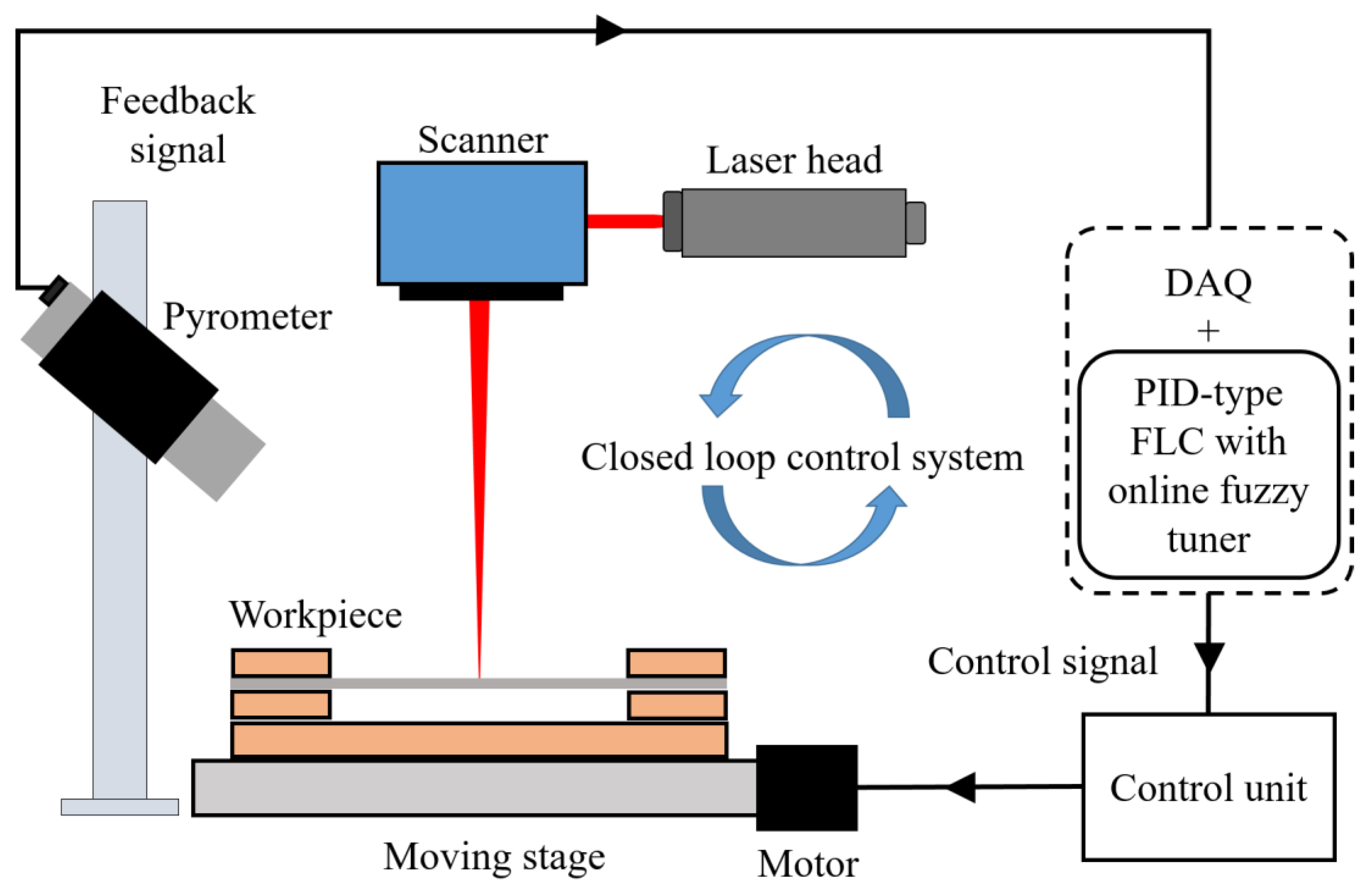
Figure 2.
Schematic diagram of (a) specimen size and (b) laser cutting of a circular path.

Figure 3.
(a) Triangular wave of input speed for laser cutting system identification and (b) corresponding output temperature variation.
Figure 3.
(a) Triangular wave of input speed for laser cutting system identification and (b) corresponding output temperature variation.

Figure 4.
Block diagram of the self-tuning PID-type FLC using online fuzzy tuner for laser cutting.

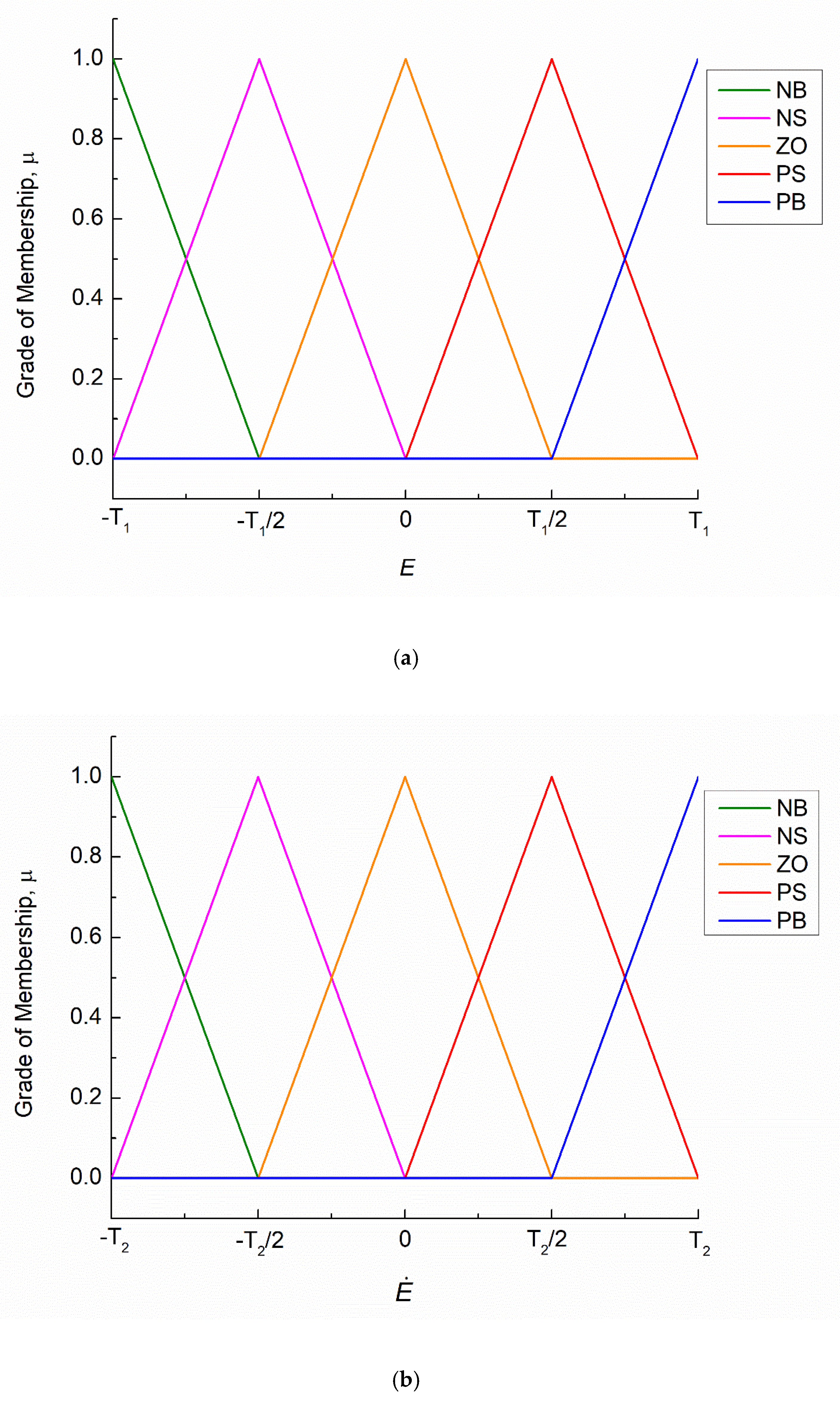
Figure 6.
Singleton membership functions used for the output variable U [31].
Figure 6.
Singleton membership functions used for the output variable U [31].

Figure 7.
Membership functions of adjustable parameters (T3, T4, and T5): (a) input variable e; (b) input variable ; and (c) output variable γ.
Figure 7.
Membership functions of adjustable parameters (T3, T4, and T5): (a) input variable e; (b) input variable ; and (c) output variable γ.
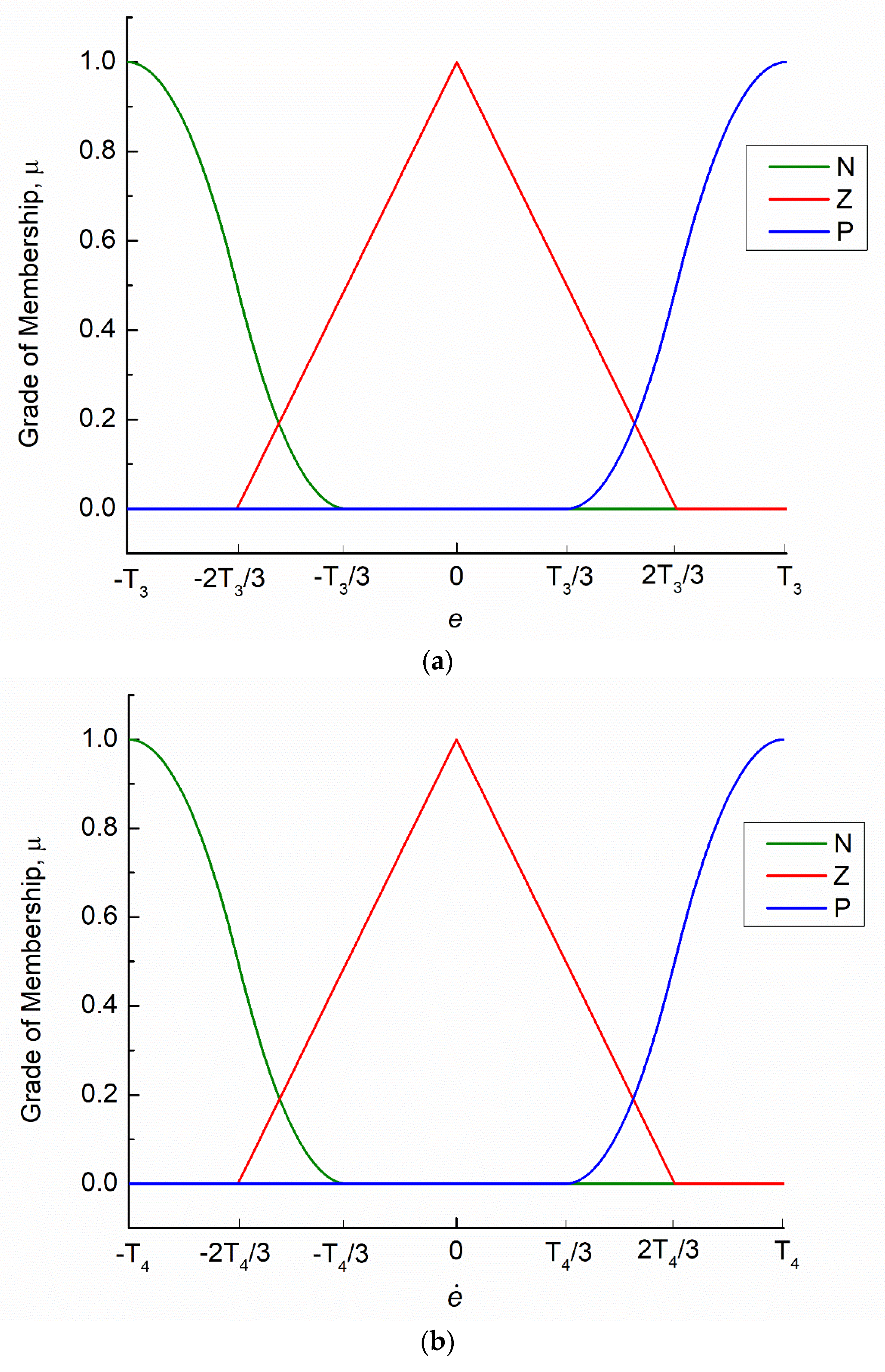
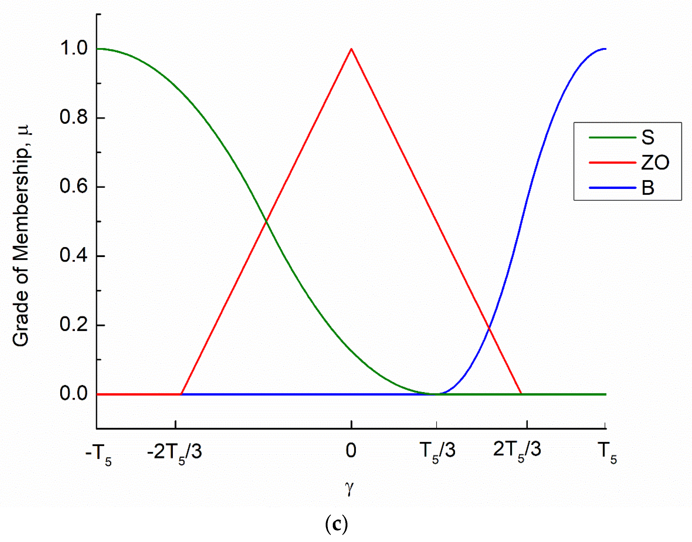
Figure 8.
Measured temperature for (a) closed-loop control with a set-point temperature of 0.7 V, (b) closed-loop control with a set-point temperature of 0.8 V, and (c) open-loop control with a constant cutting speed of 0.5 mm/s at a laser pulse frequency of 20 kHz.
Figure 8.
Measured temperature for (a) closed-loop control with a set-point temperature of 0.7 V, (b) closed-loop control with a set-point temperature of 0.8 V, and (c) open-loop control with a constant cutting speed of 0.5 mm/s at a laser pulse frequency of 20 kHz.

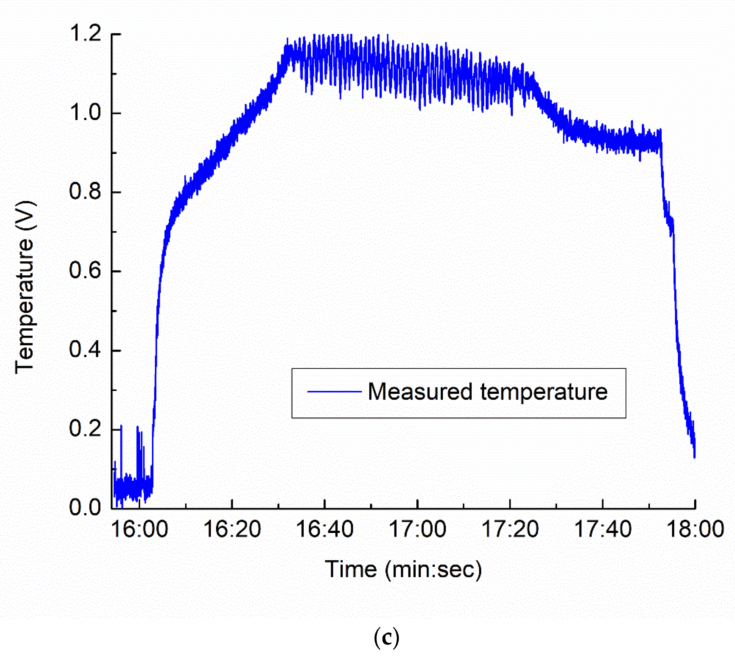
Figure 9.
Variation in roundness with cutting speed under open-loop control at pulse frequencies (a) 20 kHz and (b) 40 kHz.
Figure 9.
Variation in roundness with cutting speed under open-loop control at pulse frequencies (a) 20 kHz and (b) 40 kHz.
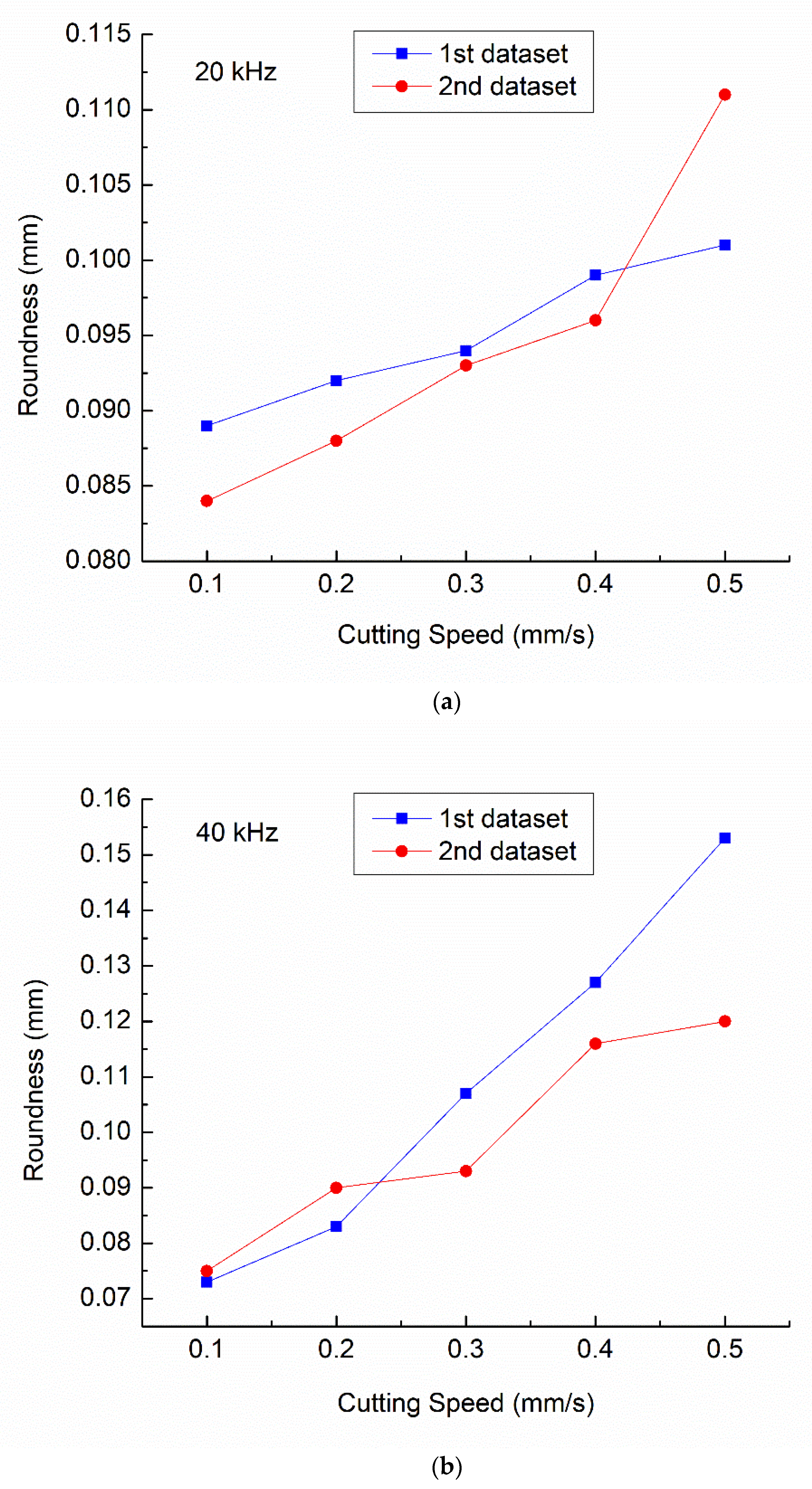
Figure 10.
Optical micrographs of HAZ under open-loop control with a constant cutting speed at 20 kHz: (a) 0.1 mm/s; (b) 0.2 mm/s; (c) 0.3 mm/s; (d) 0.4 mm/s; and (e) 0.5 mm/s.
Figure 10.
Optical micrographs of HAZ under open-loop control with a constant cutting speed at 20 kHz: (a) 0.1 mm/s; (b) 0.2 mm/s; (c) 0.3 mm/s; (d) 0.4 mm/s; and (e) 0.5 mm/s.
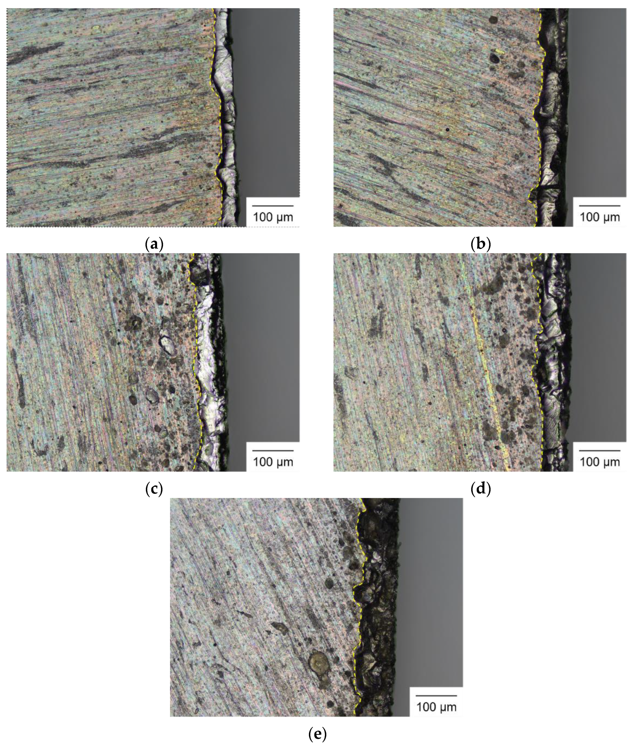
Figure 11.
Representative optical micrographs of HAZ under closed-loop control with adjusted cutting speed at 20 kHz: (a) 0.7 V and (b) 0.8 V.
Figure 11.
Representative optical micrographs of HAZ under closed-loop control with adjusted cutting speed at 20 kHz: (a) 0.7 V and (b) 0.8 V.

Figure 12.
Optical micrographs of HAZ under open-loop control with a constant cutting speed at 40 kHz: (a) 0.1 mm/s; (b) 0.2 mm/s; (c) 0.3 mm/s; (d) 0.4 mm/s; and (e) 0.5 mm/s.
Figure 12.
Optical micrographs of HAZ under open-loop control with a constant cutting speed at 40 kHz: (a) 0.1 mm/s; (b) 0.2 mm/s; (c) 0.3 mm/s; (d) 0.4 mm/s; and (e) 0.5 mm/s.
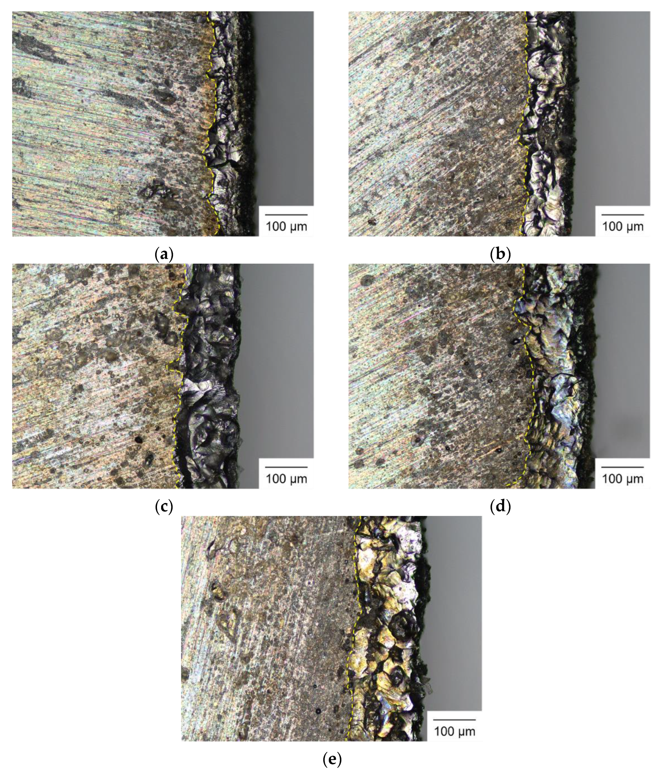
Figure 13.
Representative optical micrographs of HAZ under closed-loop control with adjusted cutting speed at 40 kHz: (a) 0.7 V; and (b) 0.8 V.
Figure 13.
Representative optical micrographs of HAZ under closed-loop control with adjusted cutting speed at 40 kHz: (a) 0.7 V; and (b) 0.8 V.

Table 1.
Process parameters for laser cutting.
| Parameter | Open Loop | Closed Loop |
|---|---|---|
| Cutting speed (mm/s) | 0.1, 0.2, 0.3, 0.4, and 0.5 | Adjusted from 0.1 to 0.7 |
| Laser power (W) | 14.07 | 14.07 |
| Pulse width (ns) | 100 | 100 |
| Pulse frequency (kHz) | 20, 40 | 20, 40 |
| Spot diameter (μm) | 50 | 50 |
| Focal length (mm) | 330 | 330 |
| Wavelength (nm) | 1064 | 1064 |
Table 2.
Fuzzy tuner rules for γ.
| e | |||
|---|---|---|---|
| N | Z | P | |
| N | ZO | ZO | ZO |
| Z | B | B | B |
| P | ZO | ZO | ZO |
Table 3.
Roundness measurements under closed-loop control at pulse frequencies of 20 kHz and 40 kHz.
Table 3.
Roundness measurements under closed-loop control at pulse frequencies of 20 kHz and 40 kHz.
| Temperature Set-Point (V) | Roundness at 20 kHz (mm) | Roundness at 40 kHz (mm) | ||||
|---|---|---|---|---|---|---|
| 1st Sample | 2nd Sample | 3rd Sample | 1st Sample | 2nd Sample | 3rd Sample | |
| 0.7 | 0.052 | 0.056 | 0.061 | 0.064 | 0.057 | 0.061 |
| 0.8 | 0.070 | 0.065 | 0.070 | 0.072 | 0.076 | 0.074 |
Disclaimer/Publisher’s Note: The statements, opinions and data contained in all publications are solely those of the individual author(s) and contributor(s) and not of MDPI and/or the editor(s). MDPI and/or the editor(s) disclaim responsibility for any injury to people or property resulting from any ideas, methods, instructions or products referred to in the content. |
© 2023 by the authors. Licensee MDPI, Basel, Switzerland. This article is an open access article distributed under the terms and conditions of the Creative Commons Attribution (CC BY) license (https://creativecommons.org/licenses/by/4.0/).
Share and Cite
MDPI and ACS Style
Nguyen, D.-T.; Lin, Y.-T.; Ho, J.-R.; Tung, P.-C.; Lin, C.-K. Temperature-Controlled Laser Cutting of an Electrical Steel Sheet Using a Novel Fuzzy Logic Controller. Mathematics 2023, 11, 4769. https://doi.org/10.3390/math11234769
AMA Style
Nguyen D-T, Lin Y-T, Ho J-R, Tung P-C, Lin C-K. Temperature-Controlled Laser Cutting of an Electrical Steel Sheet Using a Novel Fuzzy Logic Controller. Mathematics. 2023; 11(23):4769. https://doi.org/10.3390/math11234769
Chicago/Turabian StyleNguyen, Dinh-Tu, Yuan-Ting Lin, Jeng-Rong Ho, Pi-Cheng Tung, and Chih-Kuang Lin. 2023. "Temperature-Controlled Laser Cutting of an Electrical Steel Sheet Using a Novel Fuzzy Logic Controller" Mathematics 11, no. 23: 4769. https://doi.org/10.3390/math11234769
Note that from the first issue of 2016, this journal uses article numbers instead of page numbers. See further details here.