Article

Investigation of Warning Thresholds for the Deformation of GINA Gasket of Immersed Tunnel Based on a Material-to-Mechanical Analysis

1
Tunnel and Underground Engineering Branch, China Merchants Chongqing Communications Technology Research & Design Institute Co., Ltd., Chongqing 400067, China
2
School of Naval Architecture, Ocean and Civil Engineering, Shanghai Jiao Tong University, Shanghai 200240, China
3
State Key Laboratory of Coal Mine Dynamics and Control, Chongqing University, Chongqing 400044, China
4
Hong Kong-Zhuhai-Macao Bridge Authority, Zhuhai 519060, China
5
Department of Construction Engineering, Chongqing University of Science & Technology, Chongqing 401331, China
*
Author to whom correspondence should be addressed.
Mathematics 2023, 11(4), 1010; https://doi.org/10.3390/math11041010
Submission received: 19 December 2022 / Revised: 7 February 2023 / Accepted: 9 February 2023 / Published: 16 February 2023

Abstract

:
As the first waterproof component of the immersed tunnel, it is very important to ensure the remaining compression of the GINA gasket to resist external water intrusion. This paper proposed a method for determining warning thresholds for the remaining compression of the GINA gasket based on a material-to-mechanical analysis. In terms of material analysis, two factors that affect the GINA gasket are investigated: rubber hardness and cross-sectional shape, and they are adopted as the basis for subsequent mechanical analysis. In terms of mechanical analysis, uneven settlement during the operation period is considered to be the major cause of joint deformation, which is further divided into four modes: bending, shear, expansion, and torsion, with the computation model of the GINA gasket established to obtain the warning threshold. After that, a graded early warning method is adopted, and corresponding thresholds are given after an investigation of previous studies, which are validated by a three-dimensional finite element analysis. The deformation monitoring data between the E28 and E29 elements of the Hong Kong–Zhuhai–Macao Bridge Immersed Tunnel are used to verify the proposed method. The results show that the GINA gasket of the Hong Kong–Zhuhai–Macao Bridge Immersed Tunnel is currently in a safe state, and its deformation is much lower than the minimum warning level.

1. Introduction

The operational environment of the immersed tunnel is complex and changeable, such as the underwater soil being soft and the siltation being serious, which easily causes uneven settlement [1]. The uneven settlement will further lead to shear, torsion, and other deformation at the immersed tunnel joint, resulting in the risk of leakage at the joint [2]. As the GINA gasket is the key component to preventing leakage from the immersed tunnel joint, the determination of its warning threshold is critical [3].
Many studies have paid attention to the leakage caused by uneven settlement of immersed tunnel joints at the beginning of the 21st century [4,5]. Ding and Liu [6] investigated the stress-strain property of the deformation for immersed tunnel joints, and the stresses of the GINA gasket and OMEGA gasket were both discussed. The stress-strain curve of the GINA gasket was fitted by experimental data, and the fitting formulas for two stages of compression deformation ≤80 mm and >80 mm were given, respectively. Liu et al. [7] proposed a mechanical model for immersed tunnel joints considering the effect of uneven settlement and identified that there is a positive proportion between the joint stiffness of the immersed tunnel and the compression stiffness of the GINA gasket. Wang et al. [8] divided the uneven longitudinal settlement of immersed tunnel joints into bending deformation and shear deformation; in addition, they discussed the longitudinal uneven settlement development trend of immersed tunnels under periodic tidal loads. However, the remaining compression of the GINA gasket is not considered in this study. To date, many studies have mainly focused on the establishment of a mechanical model for immersed tunnel joints, and there are only a few studies relating to the warning thresholds for the remaining compression of the GINA gasket during operation.
The immersed tunnel joints can be divided into rigid joints and flexible joints according to the stiffness ratio of the joint and element. Most immersed tunnels adopt flexible joints, such as the Ningbo Yongjiang immersed tunnel, the Changhong immersed tunnel, the Honggu immersed tunnel, and the Shanghai Outer-ring immersed tunnel in China [9,10,11,12]. For flexible joints, the remaining compression of the GINA gasket determines the water-tightness of the immersed tunnel joint [13]. However, there is no uniformly recognized specification for the monitoring of the GINA gasket during operation, and the establishment of the monitoring system mainly depends on design experience [14]. Therefore, the warning threshold and specification for the GINA gasket need to be further studied.
This paper intends to investigate an early warning method that can be applied to the remaining compression of the GINA gasket during operation. Thus, the warning thresholds of the deformation of immersed tunnel joints can be determined and guarantee that the structural health monitoring of the immersed tunnel plays a key role in ensuring the operational safety of the immersed tunnel.

2. Immersed Tunnel Joint and GINA Gasket

2.1. Overview of Immersed Tunnel Joint

A wide variety of immersed tunnel joints are available to provide different adaptability to differential settlement. These joints are generally classified according to the ratio between the stiffness of the joint itself and the stiffness of the element section: cast-in-place concrete joints are considered rigid, joints that do not contain shear resistance are considered flexible, and those with a stiffness ratio between the above two are considered semi-rigid and semi-flexible to semi-rigid [15,16]. Therefore, the types of immersed tunnel joints can be divided into four categories in detail: rigid joints, flexible joints, semi-rigid joints, and semi-flexible to semi-rigid joints. As the rigid joints formed by cast-in-place concrete are not considered in this study, their cross-section is not given below. The cross-sections of the other three joints are shown in Figure 1.
As shown in Figure 1, the main components of the first two joints are similar, which are the end of the steel, GINA gasket, OMEGA gasket, steel plate, and shear key. Moreover, all three types of joints adopt the GINA gasket as the first line of defense for joint waterproofing.

2.2. GINA Gasket

Many studies have revealed that the greater the compression of the GINA gasket is, the better the sealing performance, according to the field tests. Two factors mainly affect the compression of the GINA gasket: one is the rubber hardness of the GINA gasket, and the other is the cross-sectional shapes of the GINA gasket.

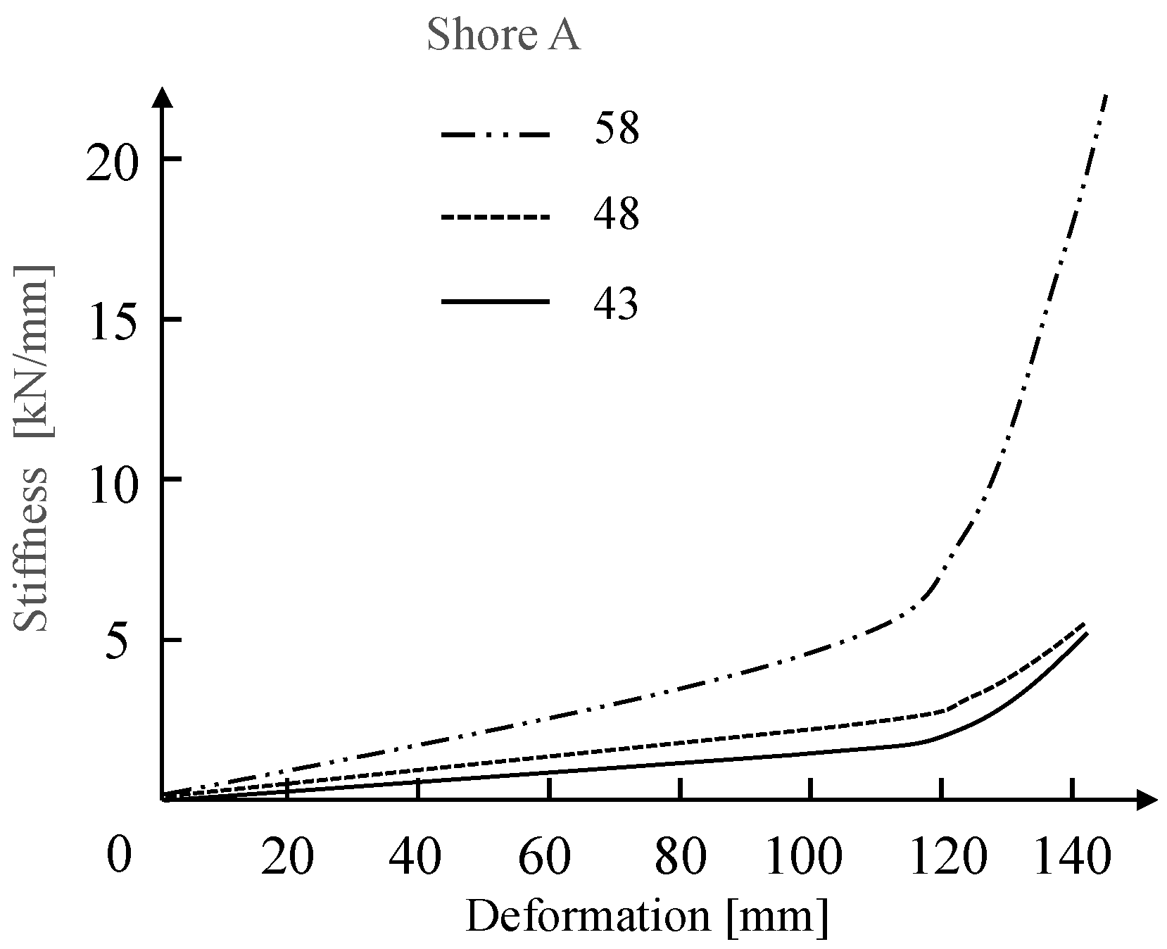
2.2.1. The Rubber Hardness of the GINA Gasket

The rubber hardness of the GINA gasket is proven to affect the deformation performance of the GINA gasket. Peng et al. [19] identified three GINA gaskets with different rubber hardness to test the deformation capacity of the GINA gasket, and the results are shown in Figure 2.
The two types with the hardness of 43 and 48 Shore A show a small change in stiffness at the same deformation, and the type with the hardness of 58 Shore A shows a large change in stiffness, according to Figure 2. The unit Shore A is a physical measure of a substance’s ability to deform under pressure or resist puncture. Shore A is generally used to characterize softer rubber materials with a hardness range of 10 to 90. The higher the value of Shore A is, the higher the hardness [20]. The influence of rubber hardness on the stiffness is not obvious when the compression deformation is less than 90 mm, and the stiffness changes significantly with increasing hardness when the compression deformation is more than 120 mm. The material characteristics of the GINA gasket with an abrupt inflection point provide an important reference for determining the threshold of waterproof failure.
In fact, the mechanical properties of the GINA gasket (made of rubber) are not determined by a single factor, such as hardness, but are also related to a variety of factors, such as the size and the frequency of the load. Its constitutive model cannot be characterized by a simple modulus of elasticity. The constitutive models of GINA gasket are mostly derived from the phenomenology theory, which assumes that rubber is homogeneous and incompressible in its undeformed state [21]. From the above assumptions, the constitutive model of the GINA gasket can be expressed as a strain energy density function, and a common model is the Mooney–Rivlin model, as shown in Equation (1).
W = C 10 ( I 1 3 ) + C 01 ( I 2 3 )
where   W is the strain energy density, and a greater density represents a greater compression stiffness; C 10 and C 01 are Rivlin constants, which depend on the rubber stiffness and are positively related to the rubber stiffness; and I 1 and I 2 represent the first and second Green strain invariants, respectively. Jiang, Bai, and Su [22] adopted Equation (1) to determine the parameters in finite element simulation for obtaining the mechanical performance of the immersed tunnel joints, including the GINA gasket and compared the results of simulation with a 1:10 scale experimental test. The two results are basically the same, which verifies the correctness of the above formula.
Therefore, based on a lot of numerical simulations and field test results, the compression of the GINA gaskets with different hardness is usually designed to be greater than 90 mm to ensure that the GINA gaskets have sufficient waterproof performance.

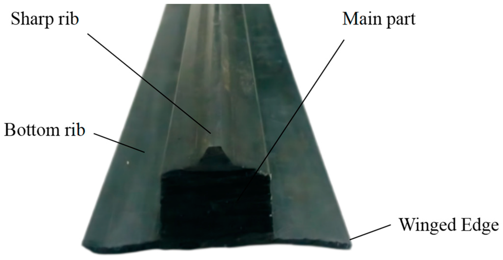
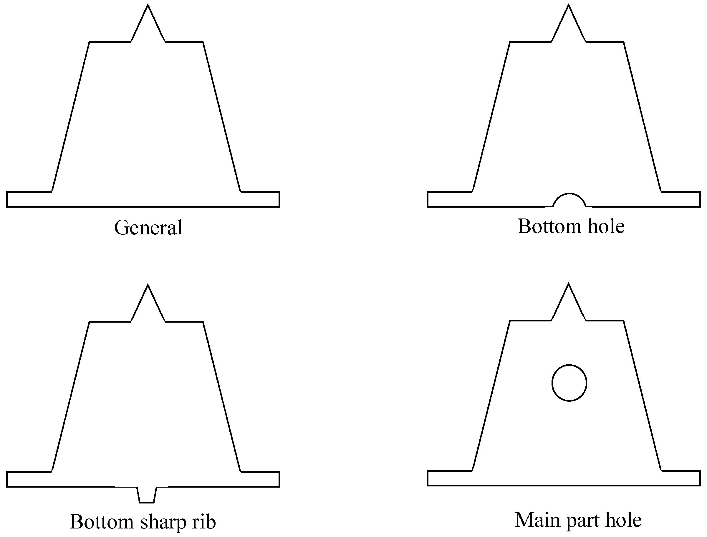
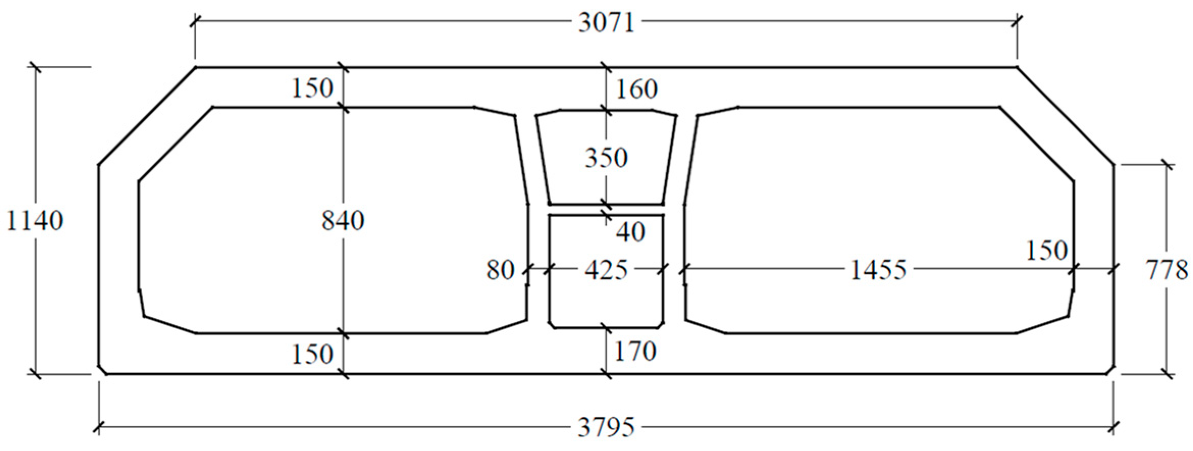
2.2.2. The Cross-Sectional Shapes of GINA Gasket

As shown in Figure 3, the traditional GINA gasket is made of rubber with a sharp rib, main part, bottom rib, and winged edge [10]. This type of GINA gasket is widely used in the Pearl River Immersed Tunnel and the Hong Kong–Zhuhai–Macao Bridge Immersed Tunnel.
The traditional GINA gasket has developed a variety of cross-sectional shapes based on years of practice. The representative ones are the TRELLEBORC type, developed in the Netherlands; the PHOENIX type, developed in Germany; the HORN type, developed in Japan; the STIRN type; and the GINA improved type. Several types of cross-sectional shapes of GINA gaskets are shown in Figure 4.
The abovementioned different cross-sectional shapes of GINA gaskets are divided into four typical types [23], and the four typical types are shown in Figure 5.
The conclusions are as follows: the type of bottom hole has the best contact with the bottom plate, so the bottom hole can improve the waterproof performance of the bottom plate. The type of sharp bottom rib is easy to overturn in the prophase of compression of the GINA gasket because of the small action area with the steel plate, which will result in poor waterproofing. The type of main part hole can significantly reduce the stress concentration of the sharp rib, which is more beneficial to the long-term waterproofing of the GINA gasket. The traditional type can better withstand the eccentric load.

3. Deformation of GINA Gasket

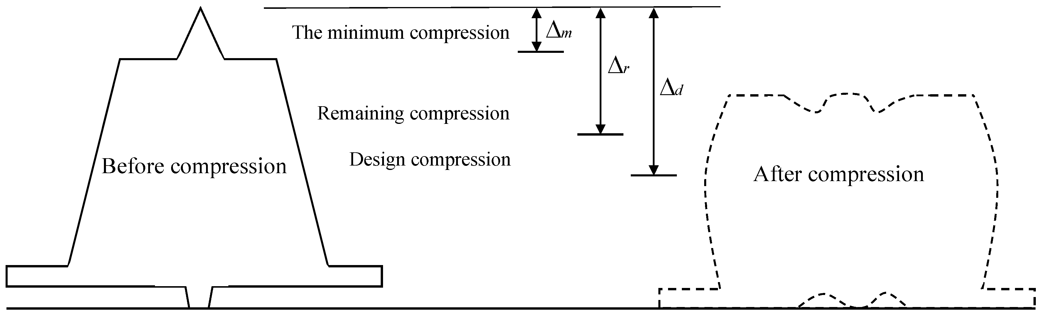
3.1. The Compression of GINA Gasket

3.1.1. The Minimum Compression of GINA Gasket

The minimum compression of the GINA gasket is determined by the magnitude of the water pressure, i.e., the higher the groundwater level in the immersed tunnel is, the higher the minimum compression needed, as shown in Figure 6.
The minimum compression of the GINA gasket Δ m can be determined according to Figure 6. To avoid the risk of errors and uncertainties, the actual remaining compression in practice should exceed the calculated minimum compression by a certain number, e.g., 20 mm, to preserve enough waterproof performance of the immersed tunnel joint during the operation [24].

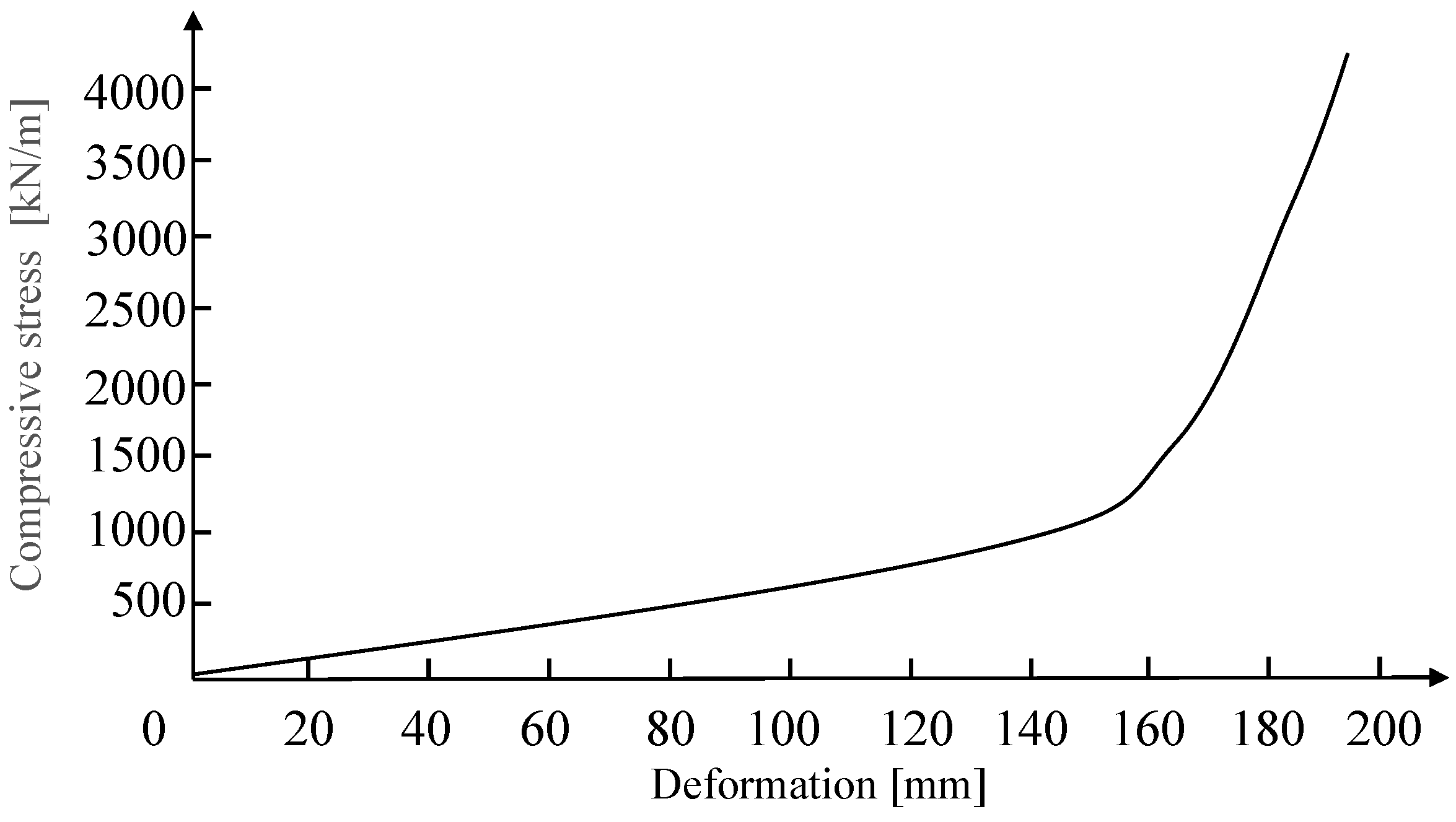
3.1.2. The Compression Characteristic of GINA Gasket

The design compression is usually not equal to the remaining compression of the GINA gasket because the remaining compression of the GINA gasket will vary due to external loads or deformations, e.g., uneven settlement. The relationship between each compression characteristic is shown in Figure 7. In the design and installation phase, the design compression Δ d is determined according to Equation (2),
F = γ × H × S C
where F is the pressure of the GINA gasket (kPa); γ is the capacitance of the water overlying the immersed tunnel (N/m3); H is the water depth to the section of the immersed tunnel joint shape center (m); S is the hydraulic crimp area of the immersed tunnel joint (m2); and C is the perimeter of the GINA gasket (m).
Δ r is the remaining compression during operation. As known above, to prevent water leakage from the immersed tunnel joint, the remaining compression of the GINA gasket should be greater than the minimum compression and should have a certain safety reserve. Moreover, the stress relaxation of the GINA gasket will occur under long time stress conditions because the GINA gasket is made of rubber. This is also a nonnegligible factor affecting the warning threshold of the GINA gasket. Hence, the warning threshold of the GINA gasket can be obtained by Equation (3),
U 0 = Δ m k + c 1 + c 2 + c 3 + c 4
Δ r = Δ d d
g n × U 0 Δ r < g n + 1 × U 0 ( n = 1 , , m )
where U 0 is the warning threshold; Δ m is the minimum compression; k is the relaxation coefficient, the range is (0, 1), and the degree of relaxation increases as the relaxation coefficient decreases; c 1 is the safety reserve (the value is generally adopted as 20 mm); c 2 is the unevenness of the surface at the joint (the value is generally 10 mm); c 3 is the longitudinal displacement of the joint caused by the temperature effect (the value is generally 10 mm); c 4 is the installation error (the value is generally 10 mm); d is the change in compression caused by uneven settlement; g n is the graded warning coefficient, and the graded warning is divided into m levels.
The warning thresholds can be obtained by calculating the minimum compression, relaxation coefficient, and constant term according to Equation (3). The remaining compression is calculated by the change in compression caused by uneven settlement according to Equation (4). The graded warning can be divided into multiple levels according to Equation (5). If the remaining compression falls into the interval of warning thresholds of different levels, corresponding measures will be taken to ensure the safety of the immersed tunnel during operation.

3.2. Deformation Modes and Computation Model

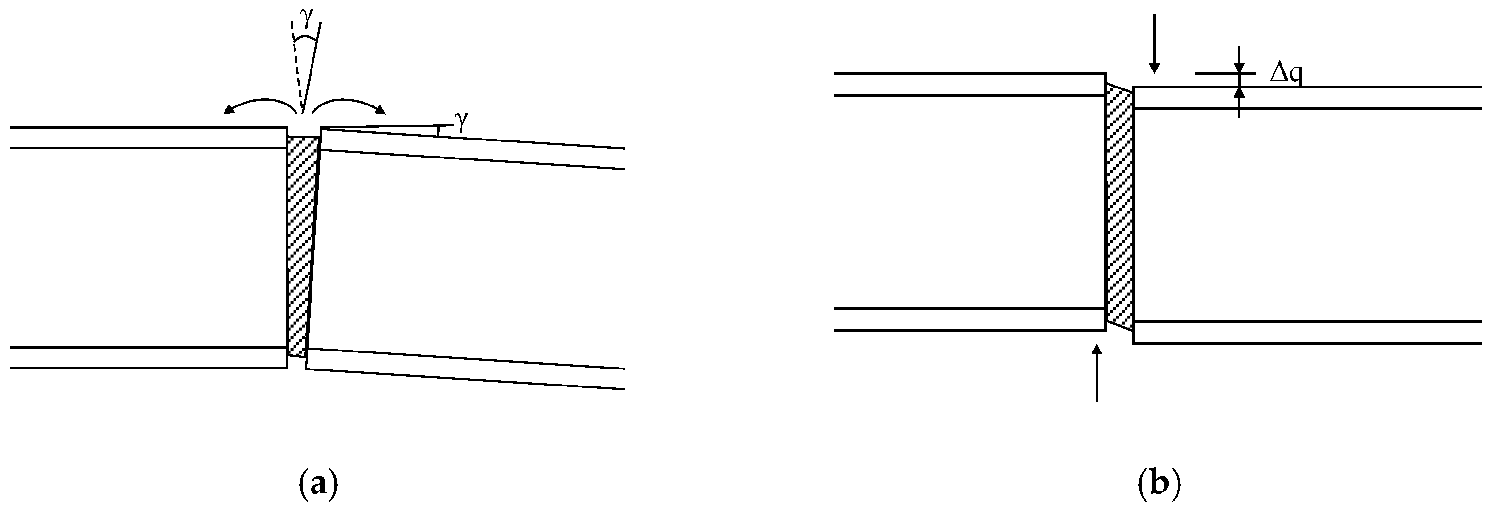
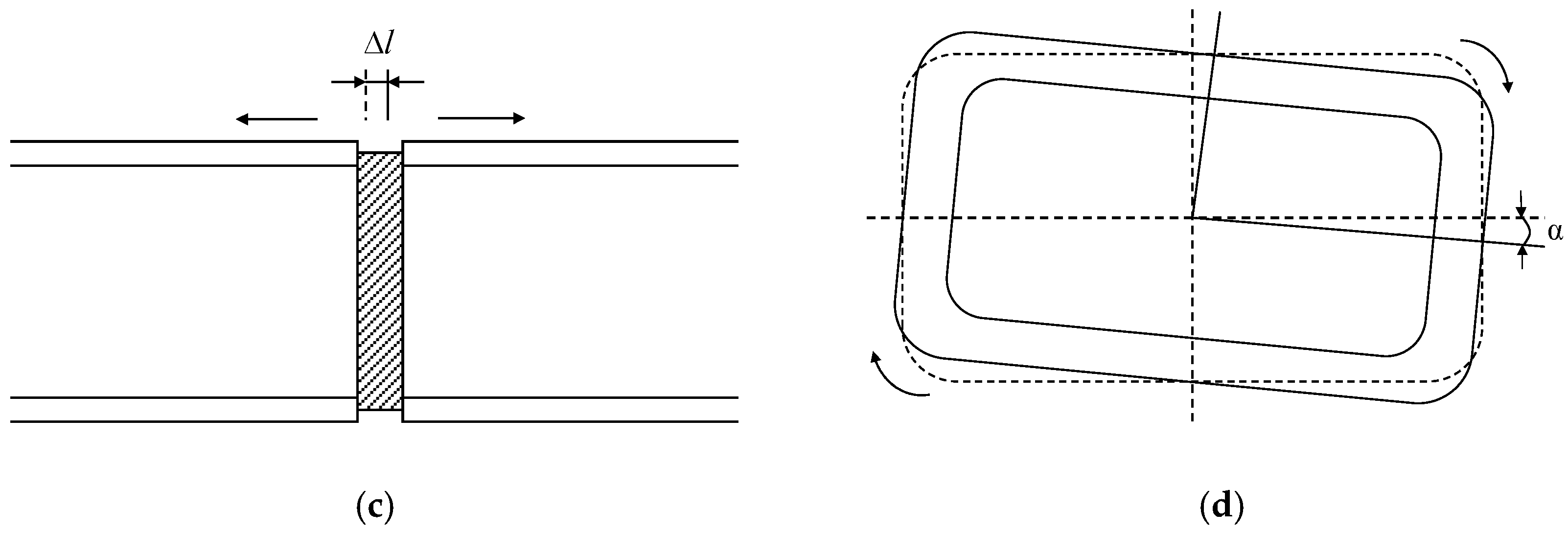
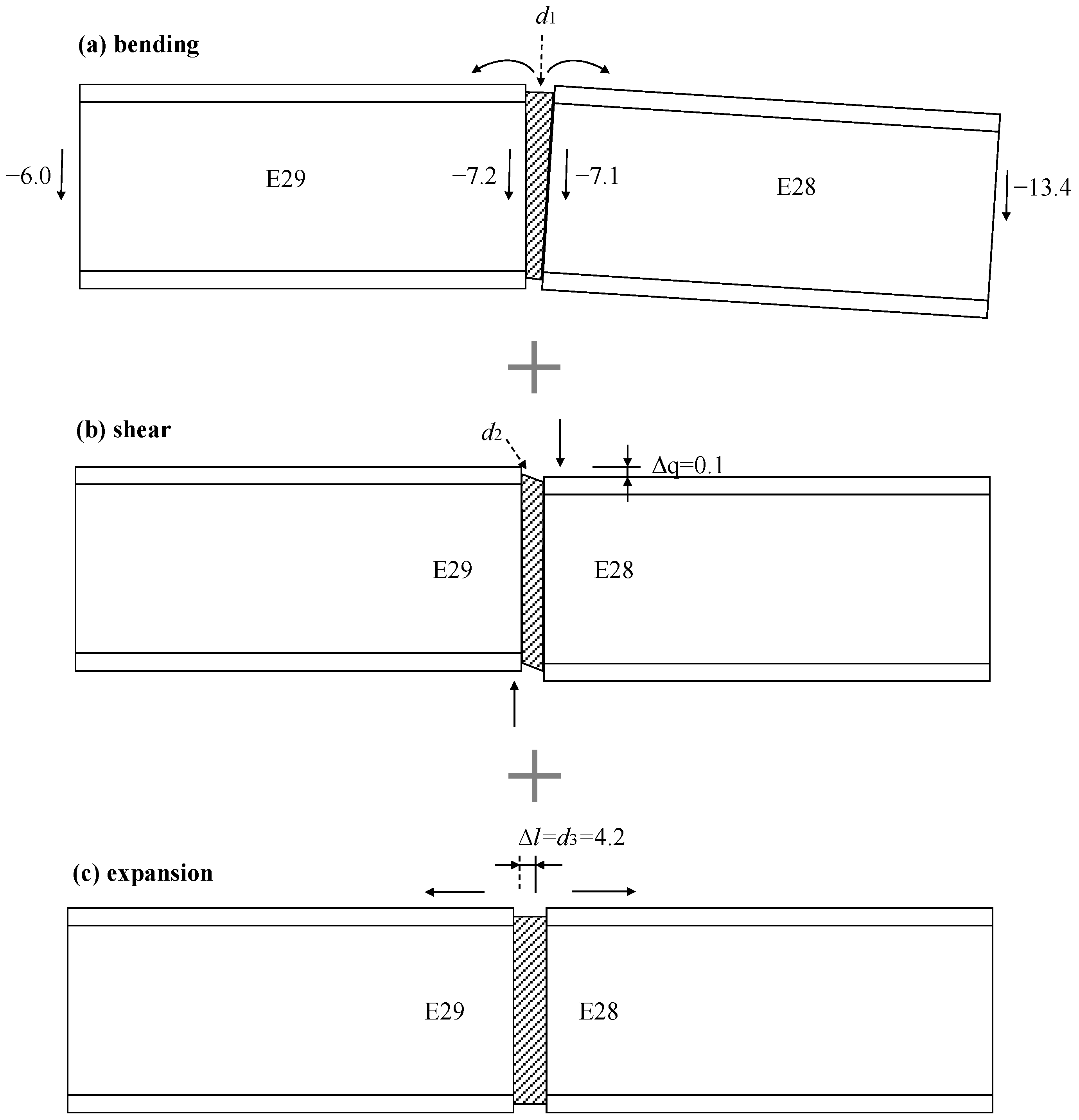
3.2.1. The Four Deformation Modes of Immersed Tunnel Joint

Regarding the change in compression caused by uneven settlement, i.e., d in Equation (4), this term can be estimated by mechanical analysis of the immersed tunnel joint. Generally, the uneven settlement of the immersed tunnel can lead to four deformation modes of the immersed tunnel joint, as shown in Figure 8, which are bending, shear, expansion, and torsion.
The formulas for calculating the change in compression due to the four deformation modes of the uneven settlement are presented as follows (revised according to HPCLab [27]).
  • Bending deformation
As shown in Figure 9, the change in compression can be obtained by Equations (6)–(9) in the case of bending deformation,
h = L · sin ( θ γ ) + Δ s = L · sin θ
d 1 = H sin γ
d 1 2 + H L cos θ ( L · sin θ Δ s ) d 1 + H 2 L 2 ( Δ s 2 2 Δ s · L · sin θ ) = 0
d 1 = H L [ sin θ L 2 ( L · sin θ Δ s ) 2 ( L · sin θ Δ s ) cos θ ]
where Δ s is the uneven settlement in the vertical direction; h is the design height difference at both ends of the elements; γ is the rotation angle caused by the deviation of the elements from the original equilibrium position; L is the length of the element; H is the vertical height of the element; H is the height difference for the installation centerline of GINA gasket; θ is the fabrication elevation of the element; and d 1 is the change in compression for the GINA gasket due to bending deformation.
The assumptions in the above geometric calculation are illustrated as follows:
(1)
The element is completely rigid, the axis of the element remains straight in the rotation, the axial length is unchanged, and the deformation of the element is negligible.
(2)
The amount of rigid body translation displacement for each element is identical, and the element under the effect of uneven settlement only produces the corresponding rotation.
(3)
The tensile stiffness of the joint is less than the compressive stiffness, and the center point of rotation is located on the compressive side of the end of the element.
(4)
The bending deformation of the joint is small.
The bending direction determines the change in the compression of each part of the GINA gasket. If the bending is counterclockwise, the compression of the GINA gasket at the top of the element increases while the compression at the bottom of the element decreases.
2.
Shear deformation
As shown in Figure 10, the change in compression can be obtained by Equation (10) in the case of shear deformation.
d 2 = Δ q 2 + B 2 B
In Figure 10 and Equation (10), B is the initial compression of the GINA gasket; Δ q is the shear deformation; and d 2 is the change in compression for the GINA gasket due to shear deformation.
The assumptions in the above geometric calculation are illustrated as follows:
(1)
The element is completely rigid, and the deformation of the element is negligible.
(2)
The element only has rigid translation in the vertical direction, and it does not produce rotation and movement in the horizontal direction.
(3)
The relative settlement is small, smaller than the shear displacement limit of the joint. There is sufficient friction between the GINA gasket and the end of the steel.
The change in compression of the GINA gasket caused by shear deformation will reduce the remaining compression. If the dislocation distance is large, the immersed tunnel joint will occur leakage, which may lead to direct damage to the immersed tunnel joint in serious situations.
3.
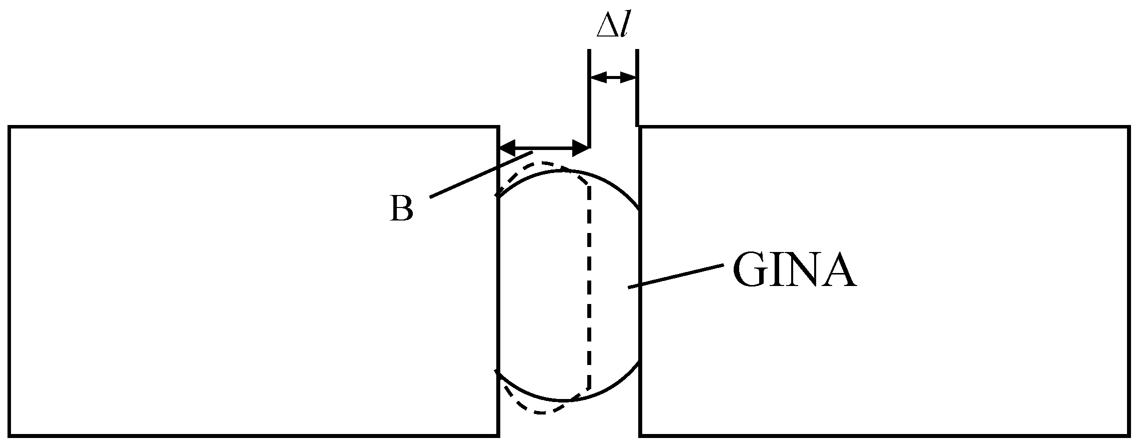
Expansion deformation
As shown in Figure 11, the change in compression can be obtained by Equation (11) in the case of expansion deformation,
d 3 = Δ l
where B is the initial compression of the GINA gasket; Δ l is the expansion deformation; and d 3 is the change in compression of the GINA gasket due to expansion deformation.
The assumptions in the above geometric calculation are illustrated as follows:
(1)
The element only has rigid body translation along the axial direction, and it does not produce rotation and uneven settlement in the vertical direction;
(2)
The deformation along the axis of the end of steel to the end of the joint can be ignored.
4.
Torsion deformation
The torsion deformation of the joint is induced by the uneven settlement along the cross-section of the element. Since the torsion deformation only occurs on the plane of the cross-section of the element and does not deform in the perpendicular direction, this minuscule torsion deformation of the joint hardly changes the compression of the GINA gasket, which can be ignored in the calculation.

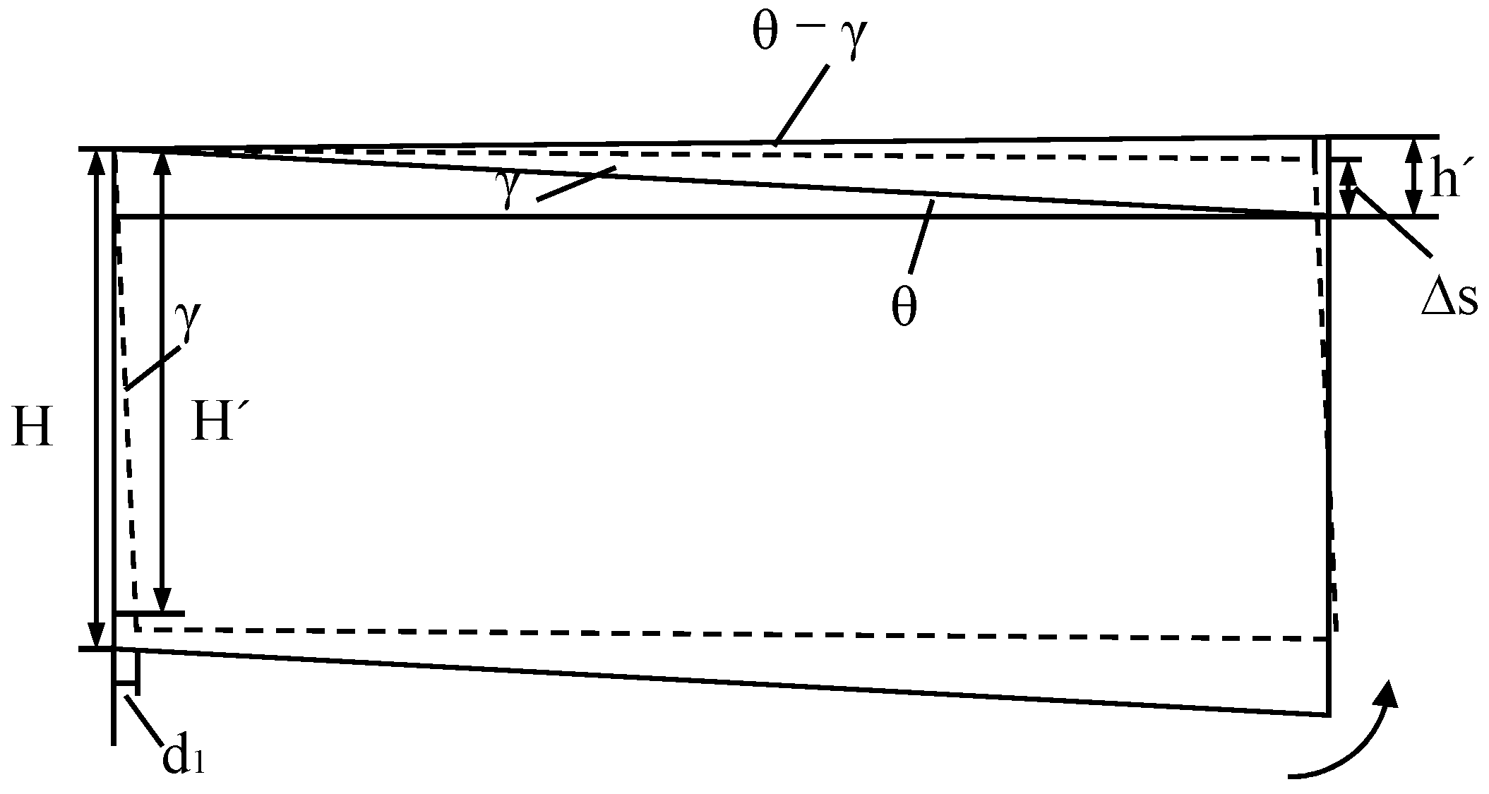
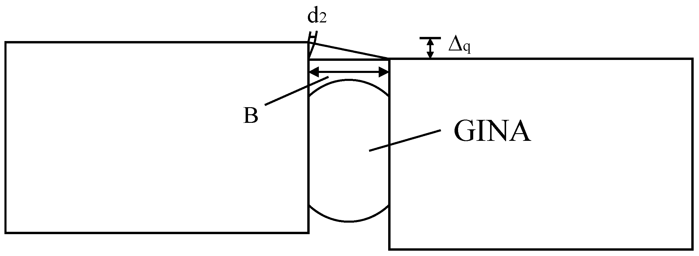
3.2.2. Formulas of Final Change of Compression

According to the analysis in Section 3.2.1, the final change in compression of the GINA gasket caused by the uneven settlement can be calculated by Equation (12).
d = d 1 + d 2 + d 3
Thus, the remaining compression of the GINA gasket can be determined according to Equations (12) and (4). This term is important because excessive change may result in insufficient remaining compression of the GINA gasket and trigger an early warning.

3.3. Estimation of Relaxation Coefficient

According to Equation (3), the relaxation coefficient is also involved in determining the warning thresholds of the GINA gasket. This paper reviews the test results related to the stress relaxation of the GINA gasket, and they are summarized in Table 1.
It can be easily estimated that the relaxation rate of the GINA gasket is positively proportional to its rubber hardness and initial compression, based on the data in Table 1. Furthermore, it is also revealed that the relaxation rate is positively proportional to the service time. The stress relaxation rate of the GINA gasket is nearly 40% after 50 years and more than 50% after 100 years [29]. Therefore, the relaxation coefficient k in Equation (3) can be estimated by Equation (13),
k = 1 s ( n ,   Δ d )
where s is the relaxation rate; n is the service time of immersed tunnel; and Δ d is the design compression.

4. Warning Method of Immersed Tunnel

4.1. Graded Warning Method

4.1.1. Graded Warning of GINA Gasket

Using monitoring data for early warning is an important measure to ensure the structural safety of the immersed tunnel, and the graded early warning method can pay attention to possible problems in advance and take corresponding measures. Liu et al. [25] gave the graded warning method for the warning threshold of each monitoring index based on the Yongjiang immersed tunnel, as shown in Table 2. Xie et al. [26] investigated the graded warning thresholds of the remaining compression of the GINA gasket, of which the stress relaxation was considered in the minimum compression of the GINA gasket.
Xu et al. [31,32] established a monitoring system for the Honggu tunnel during operation. In this study, the warning threshold of the GINA gasket was not directly obtained, but the warning threshold of the relative displacement for the immersed tunnel joint was given. The warning thresholds were divided into four grades, A, B, C, and D, where A was the best and D was the worst, as shown in Table 3.

4.1.2. The Specification of Graded Warning for GINA Gasket

Currently, there is no specification of graded warning for the structural health monitoring of the GINA gasket, but it is clearly stipulated that the compression of the GINA gasket should be monitored during the operation in the Specifications for Design of Highway Immersed Tunnel (JTG/T 3371-01—2022) [33]. The transportation administration of Jiangsu Province of China also released the latest relevant specification involving the description of the graded warning, which is the Technical Specification of Structure Health Monitoring for Underwater Tunnel (DB32/T 4243–2022) [34]. This specification proposed a unified graded warning threshold method for all monitored components, as shown in Table 4.
In the above tables, the graded warning is divided into multiple levels, and the graded warning coefficients are roughly similar to those in other studies. This classification method can be used for reference. Although a general graded warning method has been given, there is still a lack of a unified formulation method for determining the graded warning threshold of the GINA gasket during operation.

4.2. Determining the Warning Thresholds of an Immersed Tunnel

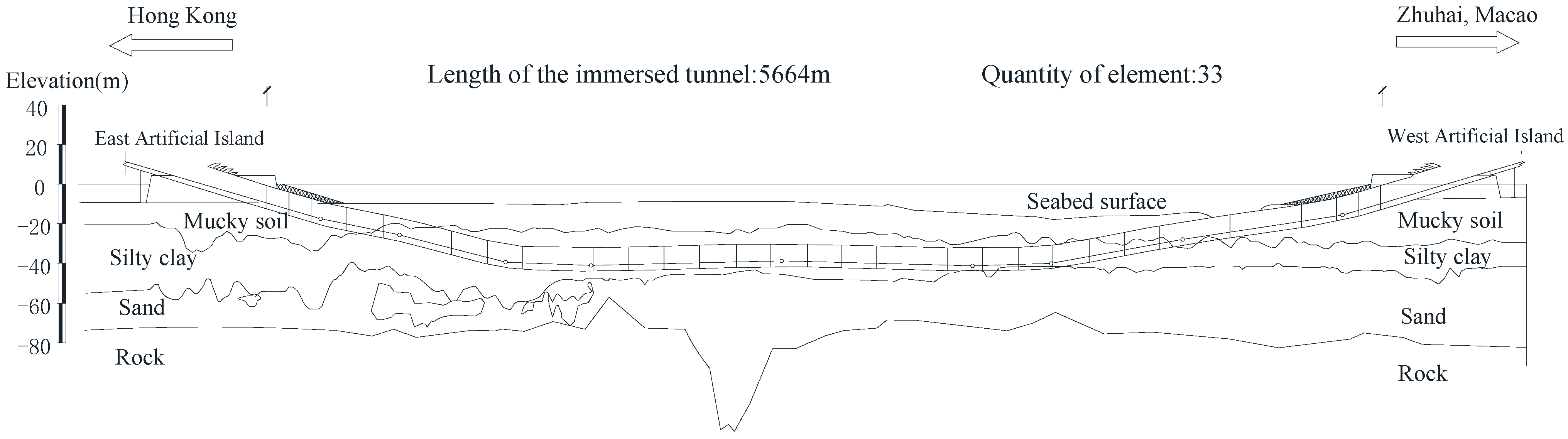
4.2.1. Outlines of the Hong Kong–Zhuhai–Macao Bridge Immersed Tunnel

This study adopts the Hong Kong–Zhuhai–Macao Bridge (HZMB) Immersed Tunnel as an illustrative example. The HZMB is a 55-km-long mega project spanning Lingdingyang Bay. It includes three components: the main project of the bridge, island, and undersea tunnel; the ports of Hong Kong, Zhuhai, and Macao; and the connecting line between the three cities. As a part of the main project, the most challenging task is the 6.7-km-long undersea tunnel [35,36]. As a complex sea-crossing project, the HZMB immersed tunnel has a transition section at the head of the artificial islands where different foundation solutions are adopted: pile foundations in the artificial island and sand compaction pile (SCP) flexible composite foundations in the transition section. More details about the foundation strategy of the HZMB immersed tunnel can be found in Hu et al. [37]. Additionally, the thickness of the placed backfill is uneven [38]. Meanwhile, the deposition of sediments should also be taken into consideration during the operation life of the structure. Load changes in the tunnel’s longitudinal direction will also result in a larger internal force in the tunnel [39,40]. All the above situations will make the operational safety of the GINA gasket of the immersed tunnel a great challenge.
The immersed tunnel section has a length of 5.67 km and consists of 33 elements, as shown in Figure 12. Among all the elements, E28–E33 is located on the flat curve with a radius (R) of 5500 m, and the rest are located on the straight section [41]. The closure joint is between E29 and E30, and the water depth at the bottom of the closure joint is 27.9 m. The mechanical properties of soil layers under the HZMB-immersed tunnel were extracted from recent publications [37], as shown in Table 5.
The standard tunnel element is 180 m long, consisting of eight segments, each of which stretches 22.5 m. The immersed tunnel provides a dual three-lane carriageway with a width of 2 × 14.55 m and a vertical clearance of 8.4 m, as shown in Figure 13. The GINA gasket between E28 and E29 is selected for analysis. The central elevation of the E29 element is −25.5 m. The total length of the GINA gasket of each section is 92 m.

4.2.2. Estimated Values of Thresholds and Safety Assessment

According to Equation (2) and the compressive stress–deformation curve of the GINA gasket (Figure 14), it can be estimated that the design compression of the GINA gasket of the E29 element is approximately 140 mm.
According to the elevation of the E29 element and the curve of the relationship between the minimum compression and water pressure (Figure 6), the minimum compression is approximately 35 mm. According to Section 3.3, the stress relaxation rate of the GINA gasket is estimated at 40%. Thus, the relaxation coefficient is 0.6, according to Equation (13), and the warning threshold U 0 of the GINA gasket is 108 mm, according to Equation (3).
The graded warning method is a risk management tool that is related to the risk acceptance level of managers. The HZMB is a mega-project with a low level of risk acceptance. In order to guarantee that no leakage occurs in the immersed tunnel under all warning grades, it is assumed that the contact pressure of the GINA gasket under the highest level of warning still guarantees 1–2 times the water pressure. Therefore, the warning level coefficients are initially set to 1, 0.9, 0.8, and 0.7, corresponding to blue (lowest), yellow, orange, and red (highest) warning levels, respectively. The graded warning thresholds of the remaining compression of the GINA gasket can be established, as shown in Table 6. The GINA gasket’s ability to resist water pressure at the deformations corresponding to these warning levels was verified by finite element analysis in Section 4.3.

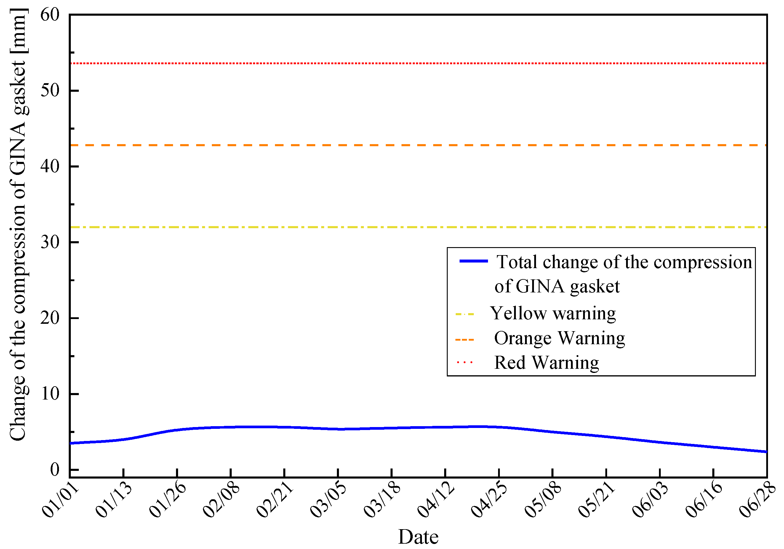
4.3. Illustrative Example of the Proposed Graded Warning Method

4.3.1. Results Identified by Simplified Formulations

Based on the uneven settlement data of E28 and E29 of the HZMB Immersed Tunnel during the first half of 2020, the total change in compression of the GINA gasket can be calculated by Equation (12). The mechanical decomposition of the deformation modes of immersed tunnel joint is presented in Figure 15.
(1)
The uneven settlement of the head and tail for E28 is 6.3 mm, and the uneven settlement of the head and tail for E29 is 1.2 mm. According to Equation (9), d 1 of the E28 and E29 elements can be calculated as 0.16 mm.
(2)
The differential post-construction settlement between the tail of E28 and the head of E29 is only 0.1 mm. According to Equation (10), d 2 of the E28 and E29 elements can be calculated as 3.6 × 10⁻⁵ mm, which can be ignored.
(3)
At the same time, there is also a compression change d 3 caused by expansion deformation. Based on the monitoring data, the maximum value of d 3 is recorded as 4.2 mm.
The summation of ( d 1 + d 2 + d 3 ) is assumed to be equal to the total change of the GINA gasket d . Then, the total change of the GINA gasket d varying with time is calculated by the monitoring data, which is shown in Figure 16.
As shown in Figure 16, the maximum total change of the GINA gasket between E28 and E29 elements does not exceed 10 mm, which means that the remaining compression of the GINA gasket is greater than 130 mm. According to Table 6, the GINA gasket between E28 and E29 elements is in a safe state, and the risk of water leakage can be assessed to be very low. The results are also consistent with the actual situation on site.

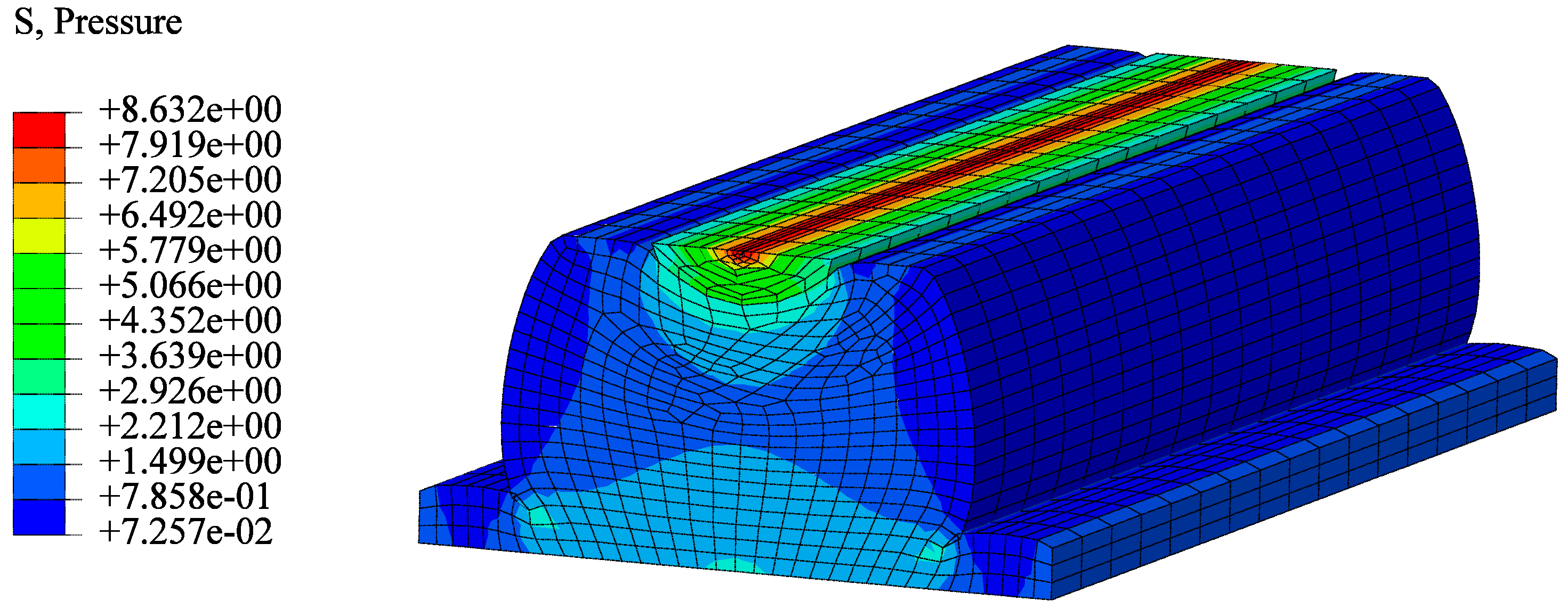
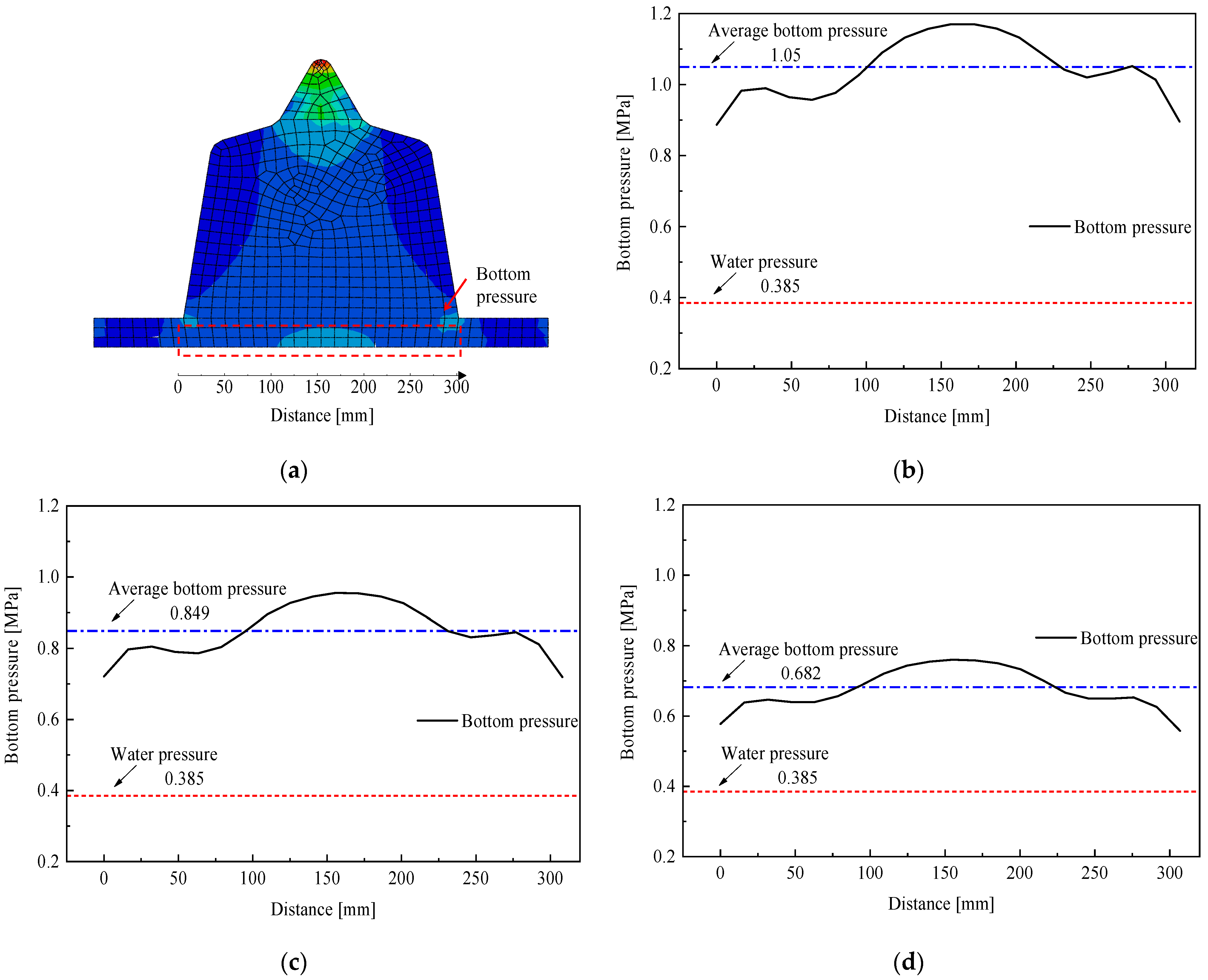
4.3.2. Results Verified by Finite Element Analysis

To further verify whether the graded warning thresholds are reasonable, a finite element analysis of the GINA gasket between E28 and E29 elements is conducted in this paper. The geometry and finite element mesh of the GINA gasket are shown in Figure 17.
The GINA gasket adopted in the immersed tunnel of HZMB is a rubber material including two parts, the nose and main body, which have different hardness. The simulation was carried out by ABAQUS, using the rubber super-elastic Mooney–Rivlin constitutive model with a C3D8H mesh and a friction factor of 0.6 between the GINA gasket and the concrete part of the immersed tunnel joint. The parameters in the Mooney–Rivlin constitutive model are shown in Table 7.
The design compression of the GINA gasket is 140 mm. Based on the average water depths of E28 and E29 and the height of the pipe section, the water pressure p w = 0.385 MPa. The design compression of 140 mm of GINA gasket is simulated in ABAQUS, and the results are shown in Figure 18. The stresses (pressure) at the top and bottom of the GINA gasket both exceed 1.5 MPa, which is much higher than the water pressure 3 × p w = 1.155 MPa. Therefore, the waterproofing capacity of the GINA gasket fully meets the requirements under the situation of design compression.
Previous GINA gasket waterproof tests showed that the leakage parts are in the bottom of the main body, and the bottom pressure is also much smaller than the tip of the nose from simulation results; thus, the analysis of the bottom pressure of the GINA gasket is more significant in practical engineering. In this study, authors set different levels of warning thresholds (remaining compression = 108 mm, 97.2 mm, 86.4 mm, respectively) as the actual compression to simulate the bottom pressure distributions of the GINA gasket and compare the ratios between the bottom pressures and the water pressure. The numerical simulation results are shown in Figure 19.
As shown in Figure 19b–d, different characteristic values of the bottom pressure of the GINA gasket are extracted, and the results of their ratios to the water pressure are shown in Table 8.
From Table 8, it is concluded that the average bottom pressures of the GINA gasket are all greater than 1.5 times the water pressure at all warning thresholds of the remaining compression, which is consistent with the assumptions in Section 4.2. In addition, the remaining compression of 86.4 mm is the most dangerous situation, at which the minimum bottom pressure of the GINA gasket is 0.558 MPa, which is close to the value of water pressure, so it is reasonable to set this value as the threshold of the red warning alert, i.e., there is a possibility of water infiltration if the remaining compression is less than this value.
Through the analysis of numerical simulation results, it can be obtained that the graded warning thresholds proposed in this study have strong feasibility in practical engineering, and the proposed method can timely determine whether there is a risk of water leakage to provide safe operation of immersed tunnels.

5. Conclusions

This study analyzed the factors affecting the compression of the GINA gasket and summarized the computation model for the deformation of the GINA gasket due to uneven settlement. The calculation formulas for determining the graded warning thresholds were given, and their feasibility was verified by a real project. The following conclusions are drawn:
(1)
The waterproof performance of the GINA gasket is directly related to the hardness of the rubber material and the cross-sectional shape. Properly increasing the rubber hardness can significantly improve the compression stiffness of the GINA gasket. The type of main part hole can significantly reduce the stress concentration of the top rib, which is more effective for long-term waterproofing.
(2)
Uneven settlement is the main reason for the increase (decrease) in the compression of the GINA gasket during operation. The bending, shear, and expansion deformation will affect the compression of the GINA gasket. Therefore, to evaluate the waterproof status of the immersed tunnel during operation, monitoring the settlements of elements and the joint opening is indispensable.
(3)
A material-to-mechanical analysis method is proposed to obtain the warning thresholds of the GINA gasket of immersed tunnels according to the material properties and mechanical computation model. This method is validated by the monitoring data at the joint of E28 and E29 of the HZMB Immersed Tunnel. The results show that there is no risk of leakage at this joint, which is consistent with the actual situation on site. The finite element analysis verified that the graded warning thresholds are feasible for different levels of leakage risks. Therefore, the proposed graded warning method for the GINA gasket is proven to be applicable to practical engineering.

Author Contributions

Conceptualization, H.D. and Q.A.; methodology, J.H. and Q.A.; software, J.H.; validation, J.H., X.J. and Y.Y.; investigation, J.C.; resources, Y.Y.; writing—original draft preparation, J.H.; writing—review and editing, Q.A. and S.D.; supervision, H.D. and S.D.; project administration, Y.Y.; funding acquisition, X.J. and H.D. All authors have read and agreed to the published version of the manuscript.

Funding

This study was funded by the National Key R&D Program of China (No.2019YFB1600702), the Chongqing Natural Science Foundation (Distinguished Youth Fund) Project (cstc2021jcyj-jqX0012), the National Natural Science Foundation of China (No.51978600), and the Natural Science Foundation of Chongqing Municipality (cstc2021jcyj-bshX0131).

Institutional Review Board Statement

Not applicable.

Informed Consent Statement

Not applicable.

Data Availability Statement

Data available on request to the authors.

Acknowledgments

We acknowledge the full support given by the Hong Kong-Zhuhai-Macao Bridge Authority.

Conflicts of Interest

The authors declare no conflict of interest.

References

  1. Olsen, T.; Kasper, T.; de Wit, J. Immersed tunnels in soft soil conditions experience from the last 20 years. Tunn. Undergr. Space Technol. 2022, 121, 104315. [Google Scholar] [CrossRef]
  2. Niu, Y.; Xie, Y.; Zhang, H.; Yue, X.; Han, Y.; Hu, Z. Study on Deformation Characteristics of Segment Joints of the Immersed Tunnel in Hong Kong-Zhuhai-Macau Bridge. Adv. Mater. Sci. Eng. 2022, 2022, 7152132. [Google Scholar] [CrossRef]
  3. Wang, W.; Luo, Y.; Kong, L.; Zhang, Y.; Chen, Y. Numerical Simulation and Experimental Study on Mechanical Properties of GINA Waterstop. Mod. Tunn. Technol. 2021, 58, 237–243. (In Chinese) [Google Scholar]
  4. Grantz, W.C. Immersed tunnel settlements. Part 1: Nature of settlements. Tunn. Undergr. Space Technol. 2001, 16, 195–201. [Google Scholar] [CrossRef]
  5. Grantz, W.C. Immersed tunnel settlements: Part 2: Case histories. Tunn. Undergr. Space Technol. 2001, 16, 203–210. [Google Scholar] [CrossRef]
  6. Ding, W.; Liu, P. Research on the Three-Dimensional Nonlinear Stiffness Mechanical Model of Immersed Tube Tunnel Joints. In Proceedings of the 2014 Geoshanghai International Congress, Shanghai, China, 26–28 May 2014. [Google Scholar]
  7. Liu, P.; Chen, J.; Chen, Y.; Yang, J.; Tang, Q. Mechanical model for joints of immersed tunnel considering the influence of joint differential settlement. Int. J. Geosynth. Ground Eng. 2020, 6, 1–10. [Google Scholar] [CrossRef]
  8. Wang, Y.N.; Zhou, H.Z.; Wang, L.C. Settlement mode analysis for an immersed tube tunnel considering a nonuniform foundation under tidal load. China Ocean Eng. 2022, 36, 427–438. [Google Scholar] [CrossRef]
  9. Xiao, W.; Yu, H.; Yuan, Y.; Taerwe, L.; Chai, R. Compression–bending behavior of a scaled immersion joint. Tunn. Undergr. Space Technol. 2015, 49, 426–437. [Google Scholar] [CrossRef]
  10. Xiao, W.; Yu, H.; Yuan, Y.; Taerwe, L.; Xu, G. Compression-shear behavior of a scaled immersion joint with steel shear keys. Tunn. Undergr. Space Technol. 2017, 70, 76–88. [Google Scholar] [CrossRef]
  11. Yu, H.; Xiao, W.; Yuan, Y.; Taerwe, L. Seismic mitigation for immersion joints: Design and validation. Tunn. Undergr. Space Technol. 2017, 67, 39–51. [Google Scholar] [CrossRef]
  12. Yu, H.; Yuan, Y.; Xu, G.; Su, Q.; Yan, X.; Li, C. Multi-point shaking table test for long tunnels subjected to non-uniform seismic loadings-part II: Application to the HZM immersed tunnel. Soil Dyn. Earthq. Eng. 2018, 108, 187–195. [Google Scholar] [CrossRef]
  13. Liu, Z.G.; Huang, H.W.; Zhang, D.M. 3D nonlinear numerical simulation on immersed tunnel joint. Undergr. Space Eng. 2011, 7, 691–694. (In Chinese) [Google Scholar]
  14. Huang, J.; Chen, X.K.; Li, H.; Zhang, Z.Y. Application of intelligent health monitoring system in underwater tunnel. Undergr. Space Eng. 2017, 13 (Suppl. 1), 306–313. (In Chinese) [Google Scholar]
  15. Song, E.; Li, P.; Lin, M.; Liu, X. The rationality of semi-rigid immersed tunnel element structure scheme and its first application in Hong Kong Zhuhai Macao bridge project. Tunn. Undergr. Space Technol. 2018, 82, 156–169. [Google Scholar] [CrossRef]
  16. GB/T 51318-2019; Standard for design of immersed tunnel. China Building Industry Press: Beijing, China, 2019.
  17. Wei, G.; Lu, S.J. Present Status and Prospects of Research on Flexible Joint Models of Immersed Tube Tunnels. Mod. Tunn. Technol. 2019, 56, 6–13. (In Chinese) [Google Scholar]
  18. Xue, Y. Research on the joint of tube tunnel. Spec. Struct. 2003, 20, 4–8. (In Chinese) [Google Scholar]
  19. Peng, L.Q.; Luo, Y.H.; Wu, X.L.; Li, B.; Lin, D.W.; Wang, J. Mechanical Property Test of Gina Seal Blet in Immersed Tunnel. Special Purpose Rubber Products 2020, 41, 56–60. (In Chinese) [Google Scholar]
  20. What is a Shore A Hardness and why is it important? Available online: https://www.barnwell.co.uk/shore-a-hardness/ (accessed on 6 February 2023).
  21. Zhang, L.; Li, Z.; Ma, X. Study on Parameter Characteristics of Rubber Mooney-rivlin model. Noise Vib. Control. 2018, 38 (Suppl. S2), 427–430. (In Chinese) [Google Scholar]
  22. Jiang, Z.W.; Bai, Y.; Su, Q.K. Element Joint Stiffness Properties of Large Immersed Tube Tunnels. Mod. Tunn. Technol. 2017, 54, 168–174. (In Chinese) [Google Scholar]
  23. Hu, Z.N.; Yang, P.; Shan, C.; Ren, Y.Z.; Dang, D. Comparative Study on Structural Types of GINA Gaskets Used in Immersed Tunnels. Tunn. Constr. 2014, 34, 937–943. (In Chinese) [Google Scholar]
  24. Tang, Y.; Guan, M.; Wan, X. The analysis and study of rail joints in immersed tunnel. China Railw. Sci. 2002, 23, 67–72. (In Chinese) [Google Scholar]
  25. Liu, Z.G.; Huang, H.W.; Zhao, Y.H.; Xie, X.Y. Immersed Tube Tunnel Real-time Health Monitoring System. Undergr. Space Eng. 2008, 4, 1110–1115. (In Chinese) [Google Scholar]
  26. Xie, X.Y.; Yi, C.M.; Li, W.P.; Fang, Y.G. Safety analysis of settlement monitoring data of joints of Yongjiang immersed tube tunnel during operation period. Chin. J. Geotech. Eng. 2019, 41, 2338–2344. (In Chinese) [Google Scholar]
  27. HPCLab. A Review Report on the Performances of Immersed Tunnel Joint; HPCLab, Tongji University: Shanghai, China, 2010. (In Chinese) [Google Scholar]
  28. Lu, M.; Zhu, Z.X.; Zhang, Y. Experimental study on watertightness of connections of pipe sections used in a large sunk pipe tunnel. China Build. Waterproofing 2003, 10, 9–12. (In Chinese) [Google Scholar]
  29. Huang, F. Numerical Simulation Analysis of GINA Rubber Water Stop. Struct. Eng. 2010, 26, 96–102. (In Chinese) [Google Scholar]
  30. Hu, J.Z.; Wang, Y.; Xu, G.P.; Xu, Y.; Yu, G.Z.; Gong, Y. Experimental Study and Selection Design of Domestic GINA Gasket for the Immersed Tunnel. Mod. Tunn. Technol. 2020, 57, 171–177. (In Chinese) [Google Scholar]
  31. Xu, X.; Tong, L.; Liu, S.; Li, H. Evaluation model for immersed tunnel health state: A case study of Honggu Tunnel, Jiangxi Province, China. Tunn. Undergr. Space Technol. 2019, 90, 239–248. [Google Scholar] [CrossRef]
  32. Xu, X.; Liu, S.; Tong, L. Establishment of Nanchang Honggu Tunnel health monitoring and assessment system. J. Southeast Univ. 2019, 35, 206–212. [Google Scholar]
  33. JTG/T 3371-01—2022; Specifications for Design of Highway Underwater Immersed Tunnel. Ministry of Transport of People’s Republic of China: Bejing, China, 2022.
  34. DB32/T 4243–2022; Technical Specification of Structure Health Monitoring for Underwater Tunnel. Jiangsu Provincial Administration of Market Supervision and Jiangsu Provincial Department of Housing and Urban-Rural Development: Nanjing, China, 2022.
  35. Hu, Z.N.; Xie, Y.L.; Wang, J. Challenges and strategies involved in designing and constructing a 6 km immersed tunnel: A case study of the Hong Kong–Zhuhai–Macao Bridge. Tunn. Undergr. Space Technol. 2015, 50, 171–177. [Google Scholar] [CrossRef]
  36. Hu, Z.; Xie, Y.; Xu, G.; Bin, S.; Liu, H.; Lai, J. Advantages and potential challenges of applying semi-rigid elements in an immersed tunnel: A case study of the Hong Kong-Zhuhai-Macao Bridge. Tunn. Undergr. Space Technol. 2018, 79, 143–149. [Google Scholar] [CrossRef]
  37. Hu, Z.N.; Xie, Y.L.; Xu, G.P.; Bin, S.L.; Zhang, H.G.; Lai, H.P.; Liu, H.Z.; Yan, C.G. Segmental joint model tests of immersed tunnel on a settlement platform: A case study of the Hongkong-Zhuhai-Macao Bridge. Tunn. Undergr. Space Technol. 2018, 78, 188–200. [Google Scholar] [CrossRef]
  38. Li, B.; Hou, J.; Min, K.; Zhang, J. Analyzing immediate settlement of Hong Kong-Zhuhai-Macao Bridge immersed tunnel based on monitoring data. Ships Offshore Struct. 2021, 16 (Suppl. 2), 100–109. [Google Scholar] [CrossRef]
  39. Jiang, X.; Lang, Q.; Jing, Q.; Wang, H.; Chen, J.; Ai, Q. An improved wavelet threshold denoising method for health monitoring data: A case study of the Hong Kong-Zhuhai-Macao Bridge immersed tunnel. Appl. Sci. 2022, 12, 6743. [Google Scholar] [CrossRef]
  40. Chen, J.; Jiang, X.; Yan, Y.; Lang, Q.; Wang, H.; Ai, Q. Dynamic Warning Method for Structural Health Monitoring Data Based on ARIMA: Case Study of Hong Kong–Zhuhai–Macao Bridge Immersed Tunnel. Sensors 2022, 22, 6185. [Google Scholar] [CrossRef] [PubMed]
  41. Lin, M.; Lin, W.; Wang, Q.; Wang, X. The deployable element, a new closure joint construction method for immersed tunnel. Tunn. Undergr. Space Technol. 2018, 80, 290–300. [Google Scholar] [CrossRef]
  42. Lin, W.; Liu, X. Analysis of GINA uneven compression during hydraulic connection of immersed tunnel element at curved plane design line. China Harbour Engineering 2016, 36, 51–53, 76. (In Chinese) [Google Scholar]
Figure 1. The different types of immersed tunnel joints (redrawn according to Wei and Lu [17] and Xue [18]). (a) Semi-flexible to semi-rigid joint. (b) Semi-rigid joint. (c) Flexible joint.
Mathematics 11 01010 g001
Figure 2. Stiffness–deformation curve of the GINA gasket (redrawn according to the results of Peng et al. [19]).
Mathematics 11 01010 g002
Figure 3. The traditional GINA gasket (redrawn according to Xiao et al. [10]).
Mathematics 11 01010 g003
Figure 4. The different cross-sectional shapes of GINA gaskets (redrawn according to Hu et al. [23]).
Mathematics 11 01010 g004
Figure 5. The four typical types of GINA gaskets (redrawn according to Hu et al. [23]).
Mathematics 11 01010 g005
Figure 6. The relationship curve between the minimum compression and water pressure (redrawn according to the results of Tang, Guan and Wan [24]).
Mathematics 11 01010 g006
Figure 7. The relationship of compression characteristics of GINA gasket (redrawn according to Liu et al. [25]).
Mathematics 11 01010 g007
Figure 8. The four deformation modes of immersed tunnel joint (redrawn according to Xie et al. [26]): (a) bending; (b) shear; (c) expansion; (d) torsion.
Mathematics 11 01010 g008aMathematics 11 01010 g008b
Figure 9. Geometric diagram of bending deformation.
Mathematics 11 01010 g009
Figure 10. Geometric diagram of shear deformation.
Mathematics 11 01010 g010
Figure 11. Geometric diagram of expansion deformation.
Mathematics 11 01010 g011
Figure 12. Longitudinal layout of the HZMB immersed tunnel (redrawn according to Lin et al. [41]).
Mathematics 11 01010 g012
Figure 13. Cross-sectional geometry of the HZMB immersed tunnel (unit: cm).
Mathematics 11 01010 g013
Figure 14. The compressive stress–deformation curve of the GINA gasket (redrawn according to Lin and Liu [42]).
Mathematics 11 01010 g014
Figure 15. Mechanical decomposition of the deformation modes of immersed tunnel joint between E28 and E29 elements.
Mathematics 11 01010 g015
Figure 16. Total change of the compression of GINA gasket between E28 and E29 elements varying with time.
Mathematics 11 01010 g016
Figure 17. Geometry and finite element mesh of GINA gasket.
Mathematics 11 01010 g017
Figure 18. Stresses of GINA gasket under design compression (MPa).
Mathematics 11 01010 g018
Figure 19. Bottom pressure of GINA gasket under different remaining compressions: (a) range of bottom pressure; (b) remaining compression = 108 mm; (c) remaining compression = 97.2 mm; (d) remaining compression = 86.4 mm.
Mathematics 11 01010 g019
Table 1. Testing results of the stress relaxation rate in previous studies.
AuthorRubber Hardness (Shore A)Initial Compression (mm)Accumulated Stress Relaxation (kN/m)Estimated Stress Relaxation Rate after 100a
Lu et al. [28] (2003)658089.455%
100184.2
110317
Huang [29] (2010)/30approximately 20% of the total stress52.3%
40
50
Hu et al. [30] (2020)4850approximately 35% of the total stress30.6%
7032%
11034.3%
12543.1%
Table 2. The graded warning thresholds of Yongjiang immersed tunnel (revised according to the results of Xie et al. [26]).
Alert LevelGraded WarningColors
IVU < 0.5U0Green
III0.5U0U < 0.7U0Yellow
II0.7U0U < 0.9U0Orange
IU ≥ 0.9U0Red
Notes: U0 is the warning threshold and U is the monitoring value.
Table 3. The graded warning thresholds of Honggu tunnel (revised according to Hu et al. [31]).
IndexABCD
Joint opening (mm)≤21.621.6–2525–28.3≥28.3
Joint compression (mm)≤20.520.5–23.323.3–33.3≥33.3
Joint horizontal displacement (mm)≤2525–3030–35.3≥35.3
Uneven settlement (mm)≤3030–4040–50≥50
Table 4. The unified graded warning thresholds for monitored components of underwater tunnel (revised according to Table 6.6.8 in [34]).
Alert LevelDescriptionAlert StatusWarning Thresholds
IParticularly seriousRed warningU0
IISeriousOrange warning[0.75–1) U0
IIIRelatively seriousYellow warning[0.5–0.75) U0
IVGeneralBlue warning[0.25–0.5) U0
VNormal/<0.25 U0
Notes: U0 is the warning threshold.
Table 5. Mechanical properties of soil layers under the HZMB immersed tunnel (data extracted from Hu et al. [37]).
Soil LayerUnit Weight
(kN/m3)
Direct Shear Test
Quick ShearConsolidated Quick Shear
c (kPa) φ (°) c (kPa) φ (°)
Mucky soil17.68.07.010.016.0
Silt clay19.320.020.025.025.0
Sand21.4////
Table 6. The graded warning thresholds of the remaining compression of GINA gasket for the HZMB Immersed Tunnel.
Alert LevelDescriptionAlert StatusRemaining Compression (mm)Change of Compression (mm)
IParticularly seriousRed warning<86.4>53.6
IISeriousOrange warning[86.4–97.2)(42.8–53.6]
IIIRelatively seriousYellow warning[97.2–108)(32–42.8]
IVGeneralBlue warning≥108≤32
Table 7. Parameters of the GINA gasket constitutive model.
PartHardness
(Shore A)
C10
(MPa)
C01
(MPa)
Nose500.0120.309
Main body650.74050.1851
Table 8. Ratios of bottom pressures of GINA gasket to water pressure.
Remaining Compression (mm)Average Bottom Pressure/Water PressureMaximum Bottom Pressure/Water PressureMinimum Bottom Pressure/Water Pressure
1082.733.042.30
97.22.202.481.87
86.41.771.971.45
Disclaimer/Publisher’s Note: The statements, opinions and data contained in all publications are solely those of the individual author(s) and contributor(s) and not of MDPI and/or the editor(s). MDPI and/or the editor(s) disclaim responsibility for any injury to people or property resulting from any ideas, methods, instructions or products referred to in the content.

