Article

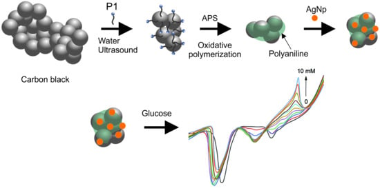
Non-Enzymatic Electrochemical Sensing of Glucose with a Carbon Black/Polyaniline/Silver Nanoparticle Composite

by
Claudia Ivone Piñón-Balderrama
1,*,
Claudia Alejandra Hernández-Escobar
1,
Simón Yobanni Reyes-López
2,
Alain Salvador Conejo-Dávila
3,
Anayansi Estrada-Monje
3 and
Erasto Armando Zaragoza-Contreras
1,*
1
Centro de Investigación en Materiales Avanzados, S.C. (Advanced Materials Research Center), Miguel de Cervantes Saavedra No. 120, Complejo Industrial Chihuahua, Chihuahua 31136, Chihuahua, Mexico
2
Institute of Biomedical Sciences, Universidad Autónoma de Ciudad Juárez (Autonomous University of Juarez City), Envolvente del PRONAF and Estocolmo s/n, Ciudad Juárez 32310, Chihuahua, Mexico
3
Centro de Innovación Aplicada en Tecnologías Competitivas (Applied Innovation Center in Advanced Technologies), Omega No. 201 Colonia Industrial Delta, León 37545, Guanajuato, Mexico
*
Authors to whom correspondence should be addressed.
Chemosensors 2024, 12(2), 26; https://doi.org/10.3390/chemosensors12020026
Submission received: 4 December 2023 / Revised: 25 January 2024 / Accepted: 29 January 2024 / Published: 9 February 2024
(This article belongs to the Special Issue Advanced Glucose Biosensors)

Abstract

:
The present work describes the synthesis of an electroactive nanocomposite consisting of carbon black (CB) and polyaniline (PANI) obtained by in situ oxidative polymerization. Monomer P1 was used as a polyaniline precursor. P1 has surfactant properties that allow obtaining core–shell structures dispersed in an aqueous medium. The nanocomposite, together with silver nanoparticles (AgNPs) as an electrocatalytic element, was used to modify the surface of a glassy carbon electrode (GCE) for glucose detection. Electroactive areas were calculated using the Randles–Sevick equation. The results showed that the CB-PANI.1-1/AgNP nanocomposite exhibited a larger electroactive surface area (0.3451 cm2) compared to AgNP alone (0.0973 cm2) or the CB-PANI.1-1 composite (0.2989 cm2). Characterization of CB-PANI.1-1/AgNP, by cyclic voltammetry in the presence of glucose, showed a new oxidation peak with a maximum current close to 0.7 V due to the oxidation of glucose to gluconolactone. The amperometry test at 0.7 V showed a linear response with R2 of 0.999 as a function of the analyte concentration. The glucose sensor presented a linear detection range of 1 to 10 mM, a sensitivity of 41 µA mM−1 cm−2, and a limit of detection (LOD) of 520 µM.

Graphical Abstract

1. Introduction

Carbon materials have played a significant role in various fields of materials science for many years. With the advent of nanotechnology, certain forms of carbon materials, such as carbon nanotubes, graphene, fullerenes, and nanodiamonds, have become increasingly important in energy storage, energy production, sensors and biosensors, and other applications [1,2,3].
However, another more traditional form of carbon, carbon black, has been around for decades, allowing innovative contributions in different specialties. Even so, with the advent of the aforementioned forms of carbon, it seems to lag behind current developments. Carbon black (CB) is a nanomaterial with a spherical nanostructure, high surface area, and excellent electrical conductivity. However, perhaps its most relevant property is its comparatively low cost regarding carbon nanotubes or graphene [4,5,6].
Although CB has been used for several decades in electrochemical sensing [7], with the emergence of carbon nanotubes or graphene it has been left out of this crucial application. Fortunately, recent studies have recovered this relevant material, and electrochemical sensors based on CB have been reported [8,9,10]. Several of these studies have shown that CB is as efficient in electrochemical electrode modification as other more sophisticated nanometer forms of carbon [5,11]. It is worth noting that CB has been used for the design of pastes for the elaboration of working electrodes for electrochemical measurements [12]; however, in this application, CB is not part of the detection element.
Combinations of CB with conductive polymers are some of the most exciting applications since their properties allow for obtaining composites with interesting electrical and electroactive properties. CB/polyaniline (PANI) systems have allowed developments in various applications. For instance, PANI/CB nanocomposites were obtained via electrochemical polymerization in the presence of CB suspensions. The core–shell morphology, determined via electron microscopy, showed that the PANI constitutes the core and CB the shell. Measurements of electrical conduction indicated a CB content dependence [13].
Regarding the use of CB/PANI composite in the design of sensors, the literature indicates that this type of system has been little studied. A PANI/CB composite was used as a chemo-resistive detector for biogenic amine vapors. The detector consists of PANI (doped with dodecylbenzene sulfonic acid (DBSA)) and 20 wt% CB, demonstrating a higher affinity for butylamine than other non-aminated compounds [14]. Likewise, a PANI/CB system (where CB is the doping agent) was used for ammonium detection. 2,3,5,6-tetrafluoro-7,7,8,8-tetracyanoquinodimethane (F4TCNQ) was the doping agent for PANI. The study focused on the comparison of both doping agents. Electrical resistance measurements indicated that with increasing dopant loading, the resistance decreased. Electrical resistance tests showed better performance when the doping agent was F4TCNQ. The authors attributed this result to an inhomogeneous dispersion of CB in the PANI [15]. As for electrochemical sensing, a PANI/CB system was applied for the oxidation of methanol, where a platinum catalyst was responsible for the electrocatalysis [16].
Assessment of glucose levels in both people and foods is an essential tool for the management of human health and the production of safe and nutritious foods. In the case of humans, it contributes to the control of diseases such as diabetes and, in general, the control of metabolic health. In this sense, the development of electrochemical glucose sensors that exhibit real-time monitoring, are non-intrusive, easy to use, and low-cost is a current topic of intense research activity. In this sense, several innovative configurations and materials have been incorporated for glucose detection including, metal nanoparticles [17], carbon-based nanomaterials [18], metallic oxide [19], and conductive polymers (CP) [20]. Specifically, the use of silver nanoparticles (AgNP) has demonstrated that by the use of an anodic sweep, the formation of oxidative species is promoted, which in turn can provide an efficient and fast electrocatalytic response toward the reaction between glucose and noble metal oxides formed in positive potentials.
The literature showed that even though PANI/CB composites have been widely used for decades, functions in chemical and electrochemical sensing have been discrete. The lack of information about this relevant application opens up important potential for the development of sensing systems based on this composite. Consequently, in this work, we reported the modification of a glassy carbon electrode (GCE) with an Ag/CB/PANI core–shell composite for the non-enzymatic detection of glucose in a basic medium. To maximize the dispersion and interaction between PANI and CB, P1 (anilinium dodecyl sulfate) was used as the PANI monomer. It is worth noting that P1, due to its surface-active properties (critical micellar concentration of 2.99 mmol dm−3), allows for the stabilization of styrene emulsion polymerizations [21,22]. In this research, P1 allowed CB efficient dispersion in the aqueous phase to be later polymerized on the surface of the CB nanoparticles via oxidative polymerization. The core–shell composite was complemented with silver nanoparticles as the electrocatalyst of glucose.

2. Materials and Methods

2.1. Materials and Reagents

Carbon black (Vulkan XC 72R, Cabot, Billerica, MA, USA) was used as received. Aniline, sodium dodecyl sulfate, ammonium peroxydisulfate (APS), potassium ferrocyanide (K4[Fe(CN)6]), potassium ferricyanide (K3[Fe(CN)6]), and glucose were purchased from Aldrich Co. (Wyoming, IL, USA) Sulfuric acid was delivered by J.T. Backer (Xalostock, Mexico State, Mexico)

2.2. Characterization and Methods

2.2.1. Characterization Techniques

The morphology of the core–shell composites was analyzed using a transmission electron microscope (TEM 7700, Hitachi, Chiyoda, Tokyo, Japan); the analyses were carried out at 100 KV. The structure of PANI-P1 and CB-PANI.1-1/AgNP composite were observed with a field emission electron microscope (JSM-7401F, Jeol, Akishima, Tokyo, Japan) with an ultra-high vacuum and 1 nm resolution. Silver nanoparticles were observed using a high-resolution transmission electron microscope (JEM 2200FS, Jeol, Akishima, Tokyo, Japan) equipped with a spherical aberration corrector in the condenser lens and operated at 200 kV. Functional group characterization was performed using a Fourier-transform spectrophotometer (GX-FTIR, Perkin Elmer, Waltham, MA, USA). The spectra were obtained using the attenuated total reflectance (ATR) technique. Each spectrum corresponds to an average of 30 scans, with a resolution of 40 cm−1 in the range of 400 to 4000 cm−1. A three-electrode cell was employed to carry out the electrochemical characterization. The arrangement of electrodes included a GCE (ø = 3 mm), a platinum sheet (1 cm2), and an Ag/AgCl that were used as the working electrode, counter electrode, and reference electrode, respectively. Cyclic voltammetry (CV), electrochemical impedance spectroscopy (EIS), and linear sweep voltammetry (LSV) techniques were performed using a potentiostat (EmStat3 + blue, PalmSens, Houten, The Netherlands).

2.2.2. Core–Shell Composite Synthesis

Our group [21] previously reported the synthesis of P1 monomer. Briefly, the salt of anilinium hydrochloride was obtained by reacting aniline with hydrochloric acid in a 1:1 molar ratio using enough amount of water to dissolve the salt. Subsequently, an aqueous solution of sodium dodecyl sulfate (SDS) corresponding to a 1:1 molar ratio concerning aniline was mixed with the salt of anilinium hydrochloride. The exchange of ions produced the precipitation of the sulfate salt of anilinium due to a much lower solubility of this salt in water at room temperature. Salt purification was performed by saturating an aqueous solution at 50 °C. Finally, the solution was allowed to cool in laboratory conditions and then refrigerated at 4 °C for 12 h, and the solid precipitated was recovered by filtration and dried under vacuum at 60 °C. P1 has active surface properties, as it is analogous to SDS; the CMC is also reported in the mentioned reference. Due to this characteristic, we used it to disperse carbon black (CB) in the aqueous phase. Once the carbon black was dispersed, potassium persulfate (oxidizing agent) was added to polymerize P1 via an oxidative polymerization and obtain the PANI-P1.
Core–shell composites were prepared as follows. P1 was loaded in a glass vessel (the reactor) with 20 g of tridistilled water. Next, the reactor was placed in an oil bath warmed to 40 °C to let the P1 dissolve in the water. The solution was kept warm for 1 h with vigorous magnetic stirring. Subsequently, an amount of CB was added to prepare composites in weight ratios, as reported in Table 1. Due to the structure proposed for the composites, the designation CB-PANI (core–shell) was used, followed by 1-1, 1-2, and 1-4 to indicate the weight ratios of CB to P1. The CB was dispersed in the aqueous solution with magnetic stirring for 1 h and then the dispersion was sonicated for 15 more min in an ultrasonic bath. The reactor was then placed back in the 40 °C oil bath. Meanwhile, a solution of APS of 0.1586 g (0.6958 mmol) in 5 g of tridistilled water was prepared in a separate vessel. Once the temperature was reached, the APS solution was added to the CB dispersion to initiate the oxidative polymerization of P1 under continuous magnetic stirring. The weight ratio of APS to P1 was 1.25 to 1 and the polymerization was left for 4 h.

2.2.3. Synthesis of Silver Nanoparticles

The synthesis of silver nanoparticles (AgNPs) was carried out following the method previously reported [23]. Briefly, the synthesis was performed from a chemical reduction, in which silver nitrate was used as the metal precursor, gallic acid as the reducing agent, and sodium hydroxide as the stabilizing agent. A 10 mM silver nitrate solution was prepared under magnetic stirring, to which the reducing agent was added (100 mg of gallic acid on 10 mL of deionized water) and, subsequently, sodium hydroxide (1 M) was added dropwise to adjust the solution to pH 11.

2.2.4. Electrode Modification and Electrochemical Analysis

Firstly, the GCE was polished with an alumina suspension (0.05 µm) and rinsed thoroughly with deionized water followed by sonication in isopropanol and deionized water. Then, 10 µL of dispersion (CB-PANI.1-1, CB-PANI.1-2, and CB-PANI.1-4) with a concentration of 5 mg/mL was drop-cast on the GCE surface and left to dry. Cyclic voltammetry (CV) was achieved on the bare GCE, composites (CB-PANI.1-1, CB-PANI.1-2, or CB-PANI.1-4), and the detection system of PANI-CB.1-1/AgNP. To prepare the detection system, two suspensions were prepared. One suspension of 5 mg mL−1 of CB-PANI.1-1 and another of 10 mM of AgNP in tridistilled water. Then, 1 mL of each suspension was mixed into a vial. Subsequently, 10 µL of the mixture was drop-cast on the GCE. CV was evaluated at a potential window from −0.4 to 1.0 V and a scan rate of 100 mV s−1 during 3 cycles of oxidation–reduction. For glucose detection, only the CB-PANI.1-1/AgNP electrode was employed. For this purpose, the amperometry test was carried out applying a potential of 0.7 V. Additionally, linear sweep voltammetry was employed to evaluate this electrode response to a linear sweep of potential at a constant scan rate of 100 mV s−1.
The quantitative evaluation of glucose was achieved by employing a solution of sodium hydroxide (NaOH) 0.1 M as a supporting electrolyte. Linear sweep voltammetry was evaluated with glucose concentrations from 0 to 10 mM, using a potential window of 0.4 to 1.0 V at a scan rate of 100 mV s−1. The amperometric response of CB-PANI.1-1/AgNP in the presence of glucose was determined by applying a constant potential of 0.7 V. At the beginning of the measurement, the current was allowed to stabilize the blank (electrolyte without glucose) for 2 min. Then, the necessary volume of the standard solution (200 mM) was added to increase the concentration by 1 mM. This procedure was repeated successively until the desired final concentration was reached. The measurement was performed with a magnetic stirring of 600 rpm. A calibration curve was prepared based on three amperometric measurements; the same GCE was used, which was modified with CB-PANI.1-1/AgNP before each assay. To carry out the assays, solutions with glucose concentrations of 0 to 10 mM were analyzed.

3. Results

3.1. Morphology

As mentioned before, the main reason for the use of P1 as a polyaniline monomer is its surface-active property, which allows for obtaining aqueous dispersions of polyaniline with high stability, since P1 is a molecule analogous to sodium dodecyl sulfate, a widely used surfactant. When dispersing CB in the aqueous solutions of P1, with the assistance of ultrasound, the CB disperses quickly and homogeneously. The adsorption of P1 on the CB surface allows the disintegration of the nanomaterial agglomerations, favoring dispersion presumably at the colloidal level. Subsequent oxidative polymerization of P1 allowed the polyaniline to remain on the surface of the CB nanoparticles. It is worth noting that the study of the dispersion stability of the colloidal systems was outside the scope of this study.
The composites’ morphology, CB, and polyaniline synthesized from P1 (PANI-P1) were closely examined. Figure 1 displays the composites at low and high magnifications on the left and right sides, respectively. The images show light and dark areas, with clear areas representing CB surfaces that have not been completely covered with polyaniline and darker areas representing surfaces covered. The high-magnification images show that with an increase in the P1 content in the initial polymerizations, greater areas of the CB are covered by PANI-P1, as interpreted from Figure 1a,c,e. With higher magnifications, as seen in Figure 1b,d,f, it was observed in detail that the dark area increased with the increase in the P1 charge. Additionally, these images show some of the details of the typical CB structure in the exposed areas [6]. From this study, it was deduced that the higher the P1 content, the greater the areas of CB covered with polyaniline, which suggests the core–shell structure. Therefore, henceforth, the composites are referred to as CB-PANI.1-4, CB-PANI.1-2, and CB-PANI.1-1. Figure 1g illustrates the high-resolution image of CB, where particles smaller than 50 nm are present. Figure 1h shows the structure of the PANI-P1, which is mainly fibrous, although not very clear.

3.2. Functional Groups

Figure 2 shows the FTIR spectra of the core–shell composites and PANI-P1 as a reference. For simplicity, the spectrum of PANI-P1 is first described. In summary, the spectrum shows the typical absorptions of polyanilines, the most representative being those located between 1200 and 1600 cm−1 [24,25]. Specifically, the absorptions at 1412 cm−1 and 1549 cm−1 are, respectively, ascribed to benzenoid (N-B-N) and quinoid (N=Q=N) ring-stretching vibrations. In addition, the peaks at 1120 cm−1 and 1283 cm−1 are associated with the stretching modes of C–N bands and π-electron delocalization due to protonation, respectively. The most relevant feature of this set of spectra is that the composites show the same signal profile as polyaniline and that the intensity of the signals increases progressively with the P1 content in the polymerization. This indicates that the amount of PANI-P1 increases from CB-PANI.1-1 to CB-PANI.1-4, confirming the trend observed in the electron microscopy images.
It is worth saying that although CB has a well-known infrared spectrum with characteristic functional groups [26], in the present FTIR study none of these signals appeared. This suggests that in the three composites, the amounts of PANI deposited on the CB are such that they completely mask the CB signals. For composites with larger amounts of CB, it has been shown that the CB absorption bands are evident [27].

3.3. Electrochemical Characterization of Core–Shell Composites

Electrochemical characterization of the core–shell composites was achieved via cyclic voltammetry. Figure 3a shows the voltammograms of the three composites, with PANI-P1 and CB as the references. These measurements were performed using an electrolyte of SDS in pH 2.5 sulfuric acid solution to preserve the dodecyl sulfate counterion, which is the counterion of P1. Firstly, as noted, CB did not present any electrochemical response, i.e., it was not electroactive, as observed previously [28]. Next, the voltammogram of PANI-P1 showed, in the anodic zone, at 0.3 V and 0.85 V, the middle-peak oxidation signals of the transitions from leucoemeraldine to emeraldine and emeraldine to pernigraniline, respectively. However, in the cathodic zone, at 0.15 V and 0.7 V, the middle-peak reduction signals from pernigraniline to emeraldine and from emeraldine to leucoemeraldine appeared, respectively. As for the core–shell composites, they presented the pattern of PANI-P1 in the three cases but exhibited a higher non-Faradaic or capacitive current as the CB content increased. The CB content at the electrode surface was estimated as 0.00008, 0.00004, and 0.00002 g for CB-PANI.1-1, CB-PANI.1-2, and CB-PANI.1-4, respectively. As noted, CB-PANI.1-1, the composite with the highest content of CB exhibited the highest electroactivity since larger Faradaic current intensity peaks in the voltammograms are observed, also attributed to the greater amount of CB. The non-Faradaic current is associated with a capacitive process, such as the charging and discharging of capacitors at the electrode–electrolyte interface due to charge accumulation at the electrical interface of the electrode, while the Faradaic current is specific to redox chemical reactions that involve electron transference [29].
In contrast, its analogs presented behaviors very similar to that of PANI-P1. Figure 3b shows the analysis of the composites, PANI-P1, CB, and GCE in the ferricyanide/ferrocyanide (K4[Fe(CN)6], K3[Fe(CN)6]) redox probe, which is widely used for the characterization of modified electrodes. As observed, the voltammogram of PANI-P1 is very similar to that of the GCE. This indicates that polyaniline does not exert an electrocatalytic effect very different from the bare electrode. In the case of core–shell composites, there are important improvements in electrocatalysis regarding PANI-P1 and GCE; therefore, CB produces an improvement in the systems, and CB-PANI.1-1, again, produces the best result. The literature indicates that the increment in surface area due to the increase in the content of CB improves the behavior of the modified electrode [30]. Like surface area, dispersion also produces improvements in the performance of PANI/CB systems. A research focused on electromagnetic interference shielding (EMI) using PANI/Poloxalene/CB composites showed that at higher CB contents the dispersion of the nanomaterial becomes more uniform. This allows the formation of an interconnected network, which favors electrical conduction and EMI [31]. Similarly, PANI/dodecylbenzene sulfonic acid-modified CB (CBDBSA) composites showed that the core–shell morphology allows greater dispersion of the composite in a thermoplastic matrix, decreasing the percolation threshold [27]. Another core–shell PANI/CB system used as a microwave absorber revealed that the CB increases the electrical conductivity of the polyaniline, whose effect was dependent on the CB content. In these works, the presence of a surface activity component (Poloxalene, DBSA, and QF-DT-7100S) allowed greater dispersion of the CB into smaller conglomerates, which in turn produced better electrical conductivities than in the absence of the agent. In the present study, the P1 itself, because of its amphiphilic structure, allowed efficient dispersion of CB during oxidative polymerization, which produced systems with high CB–polyaniline interfacial interaction; consequently, the addition of an extra agent is not required. Finally, CB presented a slightly lower electrocatalytic behavior than that exhibited by CB-PANI.1-1; consequently, as commented, CB alone is an efficient electrocatalyst for the ferricyanide/ferrocyanide system.
From the two electrochemical analyses, the decision was made to continue the research focusing only on CB-PANI.1-1 for the detection of glucose since this composite presented the best electrochemical and electrocatalytic behavior. These improvements were related to a high surface area produced by the CB; however, these also indicate that at weight ratios greater than 1 to 1, the composites present behaviors that are increasingly similar to pure polyaniline, which seems not to favor electrocatalytic activity in our composites. This effect may be related to the neutral pH at which the ferricyanide/ferrocyanide redox system is evaluated, where the PANI-P1 must be in a slightly or completely de-doped state. Therefore, at higher contents of dedoped PANI, the core may be acting as an obstacle to the electronic transfer to the electrode. In the case of the CB-PANI.1-1 composite, with the lowest content of PANI, it is possible that the polyaniline coating is mainly exerting a dispersion effect on the carbon black aggregates and, thus, the electronic transfer is improved. These results also make us think about the use of composites with higher CB contents, which, according to the results, could present better electrocatalytic behavior; however, this remains pending for further analysis.

3.4. Characterization of the Electrocatalytic System and Modified Electrode

3.4.1. Morfología de AgNP y CB-PANI.1-1/AgNP

AgNP and CB-PANI.1-1/AgNP were analyzed by electron microscopy. In the high-resolution image, the AgNPs are observed, Figure 4a. As seen, the nanoparticles are spherical with a particle size of the order of 10 nm. Figure 4b portrays the image of the CB-PANI.1-1/AgNP, where the spherical morphology related to the CB particles is maintained (Figure 1a,b). In the inset, a magnified image is illustrated, in which the silver nanoparticles are observed on the core–shell surface as small black particles.

3.4.2. Analysis of Functional Groups of Silver Nanoparticles and CB-PANI.1-1/AgNP Composite

Figure 5a illustrates the infrared spectrum of the silver nanoparticles alone. Three main signals are observed in the spectrum, at 1638, 2112, and 3318 cm−1. These signals are representative of the various interactions of the nanoparticles with the functional groups of the oxidized gallic acid. Consequently, the absorptions correspond to vibrations of OH of phenol (2112 and 3318 cm−1) and carboxylic acid (1638 cm−1) [32]. The interactions of AgNP with gallic acid can be complex; however, studies of such interactions have been carried out for metallic nanoparticles and gallic acid [33].
Figure 5b shows that the absorptions observed in PANI-P1 and the three core–shell (1120, 1283, 1412, and 1549 cm−1) (Figure 2) suffered small shifts with the interaction with the silver nanoparticles. Three prominent signals at 1119, 1374, and 1600 cm−1 were observed in the spectrum of CB-PANI.1-1/AgNP. It appears that the absorptions at 1283 and 1412 cm−1 of PANI-P1 overlapped to produce the signal at 1374 cm−1 in CB-PANI.1-1/AgNP. The FTIR spectrum of CB-PANI.1-1/AgNP shares similarities with spectra reported for the characterization of silver nanoparticles synthesized in the presence of various organic components. For example, for Saccharum officinarum extract, the spectrum of the silver nanoparticles presented signals at 1630 cm−1 corresponding to the stretching of the C=O group of aldehydes and ketones, 1388 cm−1 attributed to bending of N=O of the nitro group, and 1115 cm−1 related to stretching of C-O of the ester group [34]. On the other hand, in the presence of marine macroalgae Padina sp., the spectrum showed absorptions at 1610 cm−1 representative of N-H bend of primary amines, 1384 cm−1 corresponding to stretching of N=O of nitro groups and plane bend of C-H of alkenes, and 1023 cm−1 attributed to C-N stretching of aliphatic amines [35]. In both studies, the three signals are related to the interaction of AgNP with carbonyl groups and with nitrogen-containing groups such as nitro and amino. In our case, it can be interpreted that the three signals correspond to equivalent interactions of AgNP with the amino groups (1600 and 1119 cm−1) and aromatic rings (1374 cm−1) of the polyaniline. It is worth noting that other authors also observed the shifting of signals, Figure 5b, resulting from the interaction of polyaniline with silver nanoparticles [36]. Therefore, it is not surprising that the FTIR spectrum of CB-PANI.1-1/AgNP shares important similarities with the spectra of the cited works.

3.4.3. Analysis of the Electroactive Area of the Modified Electrode

The electroactive areas of AgNP, CB-PANI.1-1, and CB-PANI.1-1/AgNP were determined via cyclic voltammetry measurements. The performance of the electrode was carried out using the system K3[Fe (CN)6]/K4[Fe (CN)6], varying scan rate from 10 to 100 mV s−1. Figure 6a,b show the voltammograms for CB-PANI.1-1 and the plots for anodic and cathodic currents, respectively. The result was subsequently used to calculate the electroactive surface area of the modified electrodes using the Randles–Sevick equation (Equation (1)):
I p a = 2.69 × 10 5   n 3 / 2 A C D v
where A is the electroactive area (cm2), n is the number of electrons involved in the redox reaction (n = 1), v is the scan rate (Vs−1), D is the diffusion coefficient (6.7 × 10⁻⁶ cm2 s−1) [37], and C the molar concentration (mol cm−3) of the ferricyanide/ferrocyanide redox probe. From Equation (1), A can be calculated from the slope of the Ipa vs. (scan rate)1/2 plot. The calculated electroactive surface area of AgNP, CB-PANI.1-1, and CB-PANI.1-1/AgNP was 0.0973 cm2, 0.2989 cm2, and 0.3451 cm2. This result evidenced that CB-PANI.1-1/AgNP has the most prominent electroactive area, which implicates a higher number of active sites for glucose interaction. The improved electrochemical response of CB-PANI.1-1/AgNP could be attributed to the creation of a network formed by interconnected particles of CB, PANI, and AgNP, with a rough and porous surface that facilitates the absorption of the analyte [24,38]. The nanostructures led to a synergistic effect with enhanced conductivity, electroactivity, and enlarged electroactive surface area with multiple active sites, making it optimal for transduction in the electrochemical sensing of glucose.

3.5. Glucose Detection Assay

The development of easy-to-use devices that may help in the diagnosis and control of the aforementioned conditions is a topic of great scientific interest. Accordingly, the synthesized nanocomposite was employed to create an electrode of a modified surface that may sense and detect the glucose concentration present in an evaluated sample. Hence, AgNP was incorporated into the electrode modified by the composite CB-PANI.1-1 to provide it with electroactive properties toward glucose [39]. To evaluate the electrocatalytic activity of CB-PANI.1-1/AgNP, the electrochemical characterization was evaluated via CV. Figure 7 shows the voltammograms of the GCE modified by CB-PANI.1-1/AgNP and pure AgNP in the absence and presence of 5 and 7 mM glucose, using 0.1 M NaOH as the electrolyte. Figure 7a shows that before the addition of the analyte, during the oxidation cycle, three distinctive signals at 0.2548, 0.4113, and 0.7593 V corresponding to the formation of a monolayer of Ag2O, a multilayer of Ag2O, and oxidation of Ag2O to AgO, respectively, were identified. During the reverse scan, the transition of the silver-oxidized species towards the formation of Ag in the metallic state is observed at 0.2961 V (AgO to Ag2O) and −0.2672 V (Ag2O to Ag) [40,41]. It has been reported that the formation of the silver-oxidized species greatly favors glucose oxidation [42]. Once the glucose was incorporated into the electrolyte, the catalytic activity of AgNPs was evident, since in the presence of 5 and 7 mM glucose, the oxidation of glucose appears at 0.6798 V in the anodic potential sweep. This signal is related to the increase in the formation of Ag2O due to the reduction of AgO caused by glucose. Consequently, this peak is correlated to glucose content [41,43]. The higher current recorded for the 7 mM peak versus the 5 mM peak is a manifestation of the sensitivity of the modified electrode towards the presence and content of glucose. The oxidation reaction mechanism of glucose in the presence of AgNPs has been reported by several authors [40,44]. Briefly, glucose is absorbed to the surface of AgNP, which contains a high concentration of silver oxide species. Subsequently, base-mediated extraction of hydrogen from the anomeric carbon of the glucose takes place, giving rise to the peak of high intensity close to 0.7 V [38,45,46]. The alcohol proton of the formed intermediated species then interacts with silver oxide, generating gluconolactone. According to the literature, the complete oxidation of glucose occurs in anodic scanning with the formation of gluconate [47]. Figure 7b demonstrates glucose oxidation by pure AgNP. In the voltammogram, the three analogous signals to those observed when the nanoparticles are part of CB-PANI.1-1/AgNP appear. However, for CB-PANI.1-1/AgNP, the signals are more amplified, which is attributed to the greater electroactive area produced by the core–shell (CB-PANI) composite. With the addition of 5 and 7 mM glucose, the signal close to 0.68 V appears, which was also described for CB-PANI.1-1/AgNP. For the pure AgNP, the glucose oxidation peak current did not vary with glucose content as in the case of CB-PANI.1-1/AgNP. This was attributed to a higher electrode saturation rate and to the poor adhesion of AgNP on the GCE surface, which causes the nanoparticles to detach from the electrode surface as the test progresses.
It is worth saying that although the sensing mechanism is the responsibility of AgNP, each component of the detection system (CB-PANI.1-1/AgNP) plays an important role. The unique morphological features provided by the CB-PANI composite supply of porous and rough surface where the analyte is easily trapped. In addition, the composite improves the distribution of metal nanoparticles onto the electrode surface, at a time that imparts stability, electrical conductivity, and efficient electron transportation by increasing the electroactive area.
Therefore, based on CV, the current close to 0.7 V could be correlated with glucose concentration, which is corroborated by linear scanning voltammetry (LSV) characterization. Determining the catalytic activity of CB-PANI.1-1/AgNP, varying the glucose concentration from 0 to 10 mM, was carried out via LSV. Figure 7c shows that the current increases proportionally with glucose concentration increment. The performance shown by CV and LSV for glucose detection was quite consistent with linear behavior, which represents an operating advantage of the material since it simplifies glucose quantification. Figure 7d shows the linearity curve of the measurements of current vs. glucose concentration; as noted, the linearity is acceptable with a correlation value R2 of 0.9548 in the range of 1 to 10 mM.
The quantitative evaluation of glucose concentration and the performance of CB-PANI.1-1/AgNP as a sensor of the analyte was evaluated by amperometry with successive additions of glucose with increments of 1 mM. The experiment was evaluated at 0.7 V in optimized conditions (100 mV s−1). Figure 8a shows the plot of i (μA) vs. t (s) and Figure 8b the calculated calibration curve. The peak current at 0.7 V was shown to be a function of glucose concentration, displaying a linear response R2 of 0.999 (3% standard deviation). CB-PANI.1-1/AgNP was evaluated as a sensor with a linear range of detection (LROD) from 1 to 10 mM, a sensitivity of 41.26 µA mM−1 cm−2, and a limit of detection (LOD) of 520 µM (LOD = 3.3 × σ/S, where σ y S are the standard deviation and sensitivity, respectively).

3.6. Interference Test

The selectivity CB-PANI.1-1/AgNP was evaluated as shown in Figure 9. This study was carried out using common interferents found in blood and biological fluids such as potassium chloride (KCl), sodium chloride (NaCl), and urea. A known concentration of the interferents was evaluated. The first signal appearing at 120 s of elapsed time corresponds to 5 mM glucose. After 60 s, KCl was added to the electrolyte; in this case, no change was recorded in the current signal. Approximately, at 240 s and 300 s of elapsed time NaCl and urea were added, respectively. In this case, the response of the material remained below 5% concerning the current recorded for glucose. The small change in current for these two interferents was attributed to (a) the interferent slightly blocking the surface of the modified electrode and then being diluted in the electrolyte and (b) the analyte being slightly diluted with the addition of the interferent. Finally, at 360 s of elapsed time, a second addition of glucose was added to the electrolyte, evidencing that the surface remains active for the detection of glucose; for this reason, it could be considered that the presence of these interferents does not affect the detection response.
To compare the performance of the proposed CB-PANI.1-1/AgNP sensor with other works that used metal nanoparticles as electrocatalytic species, PANI, or carbon nanostructures as a non-enzymatic material for glucose detection, we considered operational parameters such as LOD, sensitivity, and linearity (see Table 2). Those values are the most important parameters for an electrochemical glucose sensor and, as can be observed, the obtained results were similar for those that involve the use of more sophisticated and complicated synthesis material and hence of higher cost of production. Thus, it could be concluded that the working range and LOD are suitable for the analysis of levels of glucose to cover a wide range of concentrations that allow evaluation from normal levels (5.6 mM) in people without glycemic conditions to levels that require appropriate medical attention and care (≥7 mM).

4. Conclusions

Three composites with a core–shell morphology, carbon black/polyaniline composite, were synthesized using the amphiphilic monomer P1. This monomer is a precursor of polyaniline, and it was used to induce the dispersion of the carbon nanomaterial in an aqueous medium. The electrochemical characterization indicated that the best electrochemical behavior was obtained with a ratio of 1 to 1 of P1 to carbon black, resulting in the composite CB-PANI.1-1. The incorporation of silver nanoparticles, as an electrocatalyst, allowed the detection of glucose in the range of 1 to 10 mM in an alkaline medium. The composite showed excellent performance for the detection of the analyte, with excellent linearity and reproducibility. It has to be mentioned that even when silver nanoparticles are the component in charge of the glucose oxidation and hence the sensing of the analyte, the core–shell composite showed a higher surface area, which in turn increased the number of active sites available to carry out the oxidation reaction. Therefore, this study showed that the carbon black/polyaniline nanocomposite is an excellent carrier for silver nanoparticles because it favors the dispersion of the metal nanoparticles while generating a high electroactive area.

Author Contributions

Conceptualization, E.A.Z.-C., C.I.P.-B., A.S.C.-D., A.E.-M. and C.A.H.-E.; investigation, E.A.Z.-C., C.I.P.-B., S.Y.R.-L. and C.A.H.-E.; resources, E.A.Z.-C.; writing—original draft preparation, E.A.Z.-C. and C.I.P.-B.; writing—review and editing, E.A.Z.-C. and C.I.P.-B.; supervision, E.A.Z.-C. and C.I.P.-B.; project administration, E.A.Z.-C.; funding acquisition, E.A.Z.-C. All authors have read and agreed to the published version of the manuscript.

Funding

The Secretaría de Innovación, Ciencia y Educación Superior del Estado de Guanajuato, México, through The Program “Ciencia Productiva 2023, Impulso a Actividades Científicas y Tecnológicas (Grant Number: SOL-1279)”.

Institutional Review Board Statement

Not applicable.

Informed Consent Statement

Not applicable.

Data Availability Statement

Data are contained within the article.

Acknowledgments

We wish to thank CONAHCYT for the assignment of a Researcher position of “Investigadores por México Program” for the project “Desarrollo de plataformas de sensores químicos para detección de creatinina” awarded to Claudia Ivone Piñón-Balderrama (CVU 387600). We also thank CONAHCYT for the postdoctoral fellowship awarded to Alain S. Conejo-Dávila (627922). Finally, we thank Raúl Ochoa, Daniel Lardizabal, Manuel Román and Cesar Leyva for their valuable assistance during this research.

Conflicts of Interest

The authors declare no conflicts of interest.

References

  1. Obreja, V.V.N. On the Performance of Supercapacitors with Electrodes Based on Carbon Nanotubes and Carbon Activated Material—A Review. Phys. E Low-Dimens. Syst. Nanostructures 2008, 40, 2596–2605. [Google Scholar] [CrossRef]
  2. Yogeswaran, U.; Chen, S. Recent Trends in the Application of Carbon Nanotubes–Polymer Composite Modified Electrodes for Biosensors: A Review. Anal. Lett. 2008, 41, 210–243. [Google Scholar] [CrossRef]
  3. Lufrano, F.; Staiti, P. Mesoporous Carbon Materials as Electrodes for Electrochemical Supercapacitors. Int. J. Electrochem. Sci. 2010, 5, 903–916. [Google Scholar] [CrossRef]
  4. Han, Z.; Li, H.; Xiao, J.; Song, H.; Li, B.; Cai, S.; Chen, Y.; Ma, Y.; Feng, X. Ultralow-Cost, Highly Sensitive, and Flexible Pressure Sensors Based on Carbon Black and Airlaid Paper for Wearable Electronics. ACS Appl. Mater. Interfaces 2019, 11, 33370–33379. [Google Scholar] [CrossRef] [PubMed]
  5. Arduini, F.; Cinti, S.; Mazzaracchio, V.; Scognamiglio, V.; Amine, A.; Moscone, D. Carbon Black as an Outstanding and Affordable Nanomaterial for Electrochemical (Bio)Sensor Design. Biosens. Bioelectron. 2020, 156, 112033. [Google Scholar] [CrossRef]
  6. Khodabakhshi, S.; Fulvio, P.F.; Andreoli, E. Carbon Black Reborn: Structure and Chemistry for Renewable Energy Harnessing. Carbon N. Y. 2020, 162, 604–649. [Google Scholar] [CrossRef]
  7. Silva, T.A.; Moraes, F.C.; Janegitz, B.C.; Fatibello-Filho, O.; Ganta, D. Electrochemical Biosensors Based on Nanostructured Carbon Black: A Review. J. Nanomater. 2017, 2017, 4571614. [Google Scholar] [CrossRef]
  8. Ibáñez-Redín, G.; Silva, T.A.; Vicentini, F.C.; Fatibello-Filho, O. Effect of Carbon Black Functionalization on the Analytical Performance of a Tyrosinase Biosensor Based on Glassy Carbon Electrode Modified with Dihexadecylphosphate Film. Enzym. Microb. Technol. 2018, 116, 41–47. [Google Scholar] [CrossRef] [PubMed]
  9. Cammarota, M.; Lepore, M.; Portaccio, M.; Di Tuoro, D.; Arduini, F.; Moscone, D.; Mita, D.G. Laccase Biosensor Based on Screen-Printed Electrode Modified Withthionine-Carbon Black Nanocomposite, for Bisphenol A Detection. Electrochimica Acta 2013, 109, 340–347. [Google Scholar] [CrossRef]
  10. Vicentini, F.C.; Raymundo-Pereira, P.A.; Janegitz, B.C.; Machado, S.A.S.; Fatibello-Filho, O. Nanostructured Carbon Black for Simultaneous Sensing in Biological Fluids. Sens. Actuators B Chem. 2016, 227, 610–618. [Google Scholar] [CrossRef]
  11. Lo, T.W.B.; Aldous, L.; Compton, R.G. The Use of Nano-Carbon as an Alternative to Multi-Walled Carbon Nanotubes in Modified Electrodes for Adsorptive Stripping Voltammetry. Sens. Actuators B Chem. 2012, 162, 361–368. [Google Scholar] [CrossRef]
  12. Zhang, X.; Cui, Y.; Lv, Z.; Li, M.; Ma, S.; Cui, Z.; Kong, Q. Carbon Nanotubes, Conductive Carbon Black and Graphite Powder Based Paste Electrodes. Int. J. Electrochem. Sci. 2011, 6, 6063–6073. [Google Scholar] [CrossRef]
  13. Luo, K.; Guo, X.; Shi, N.; Sun, C. Synthesis and Characterization of Core-Shell Nanocomposites of Polyaniline and Carbon Black. Synth. Met. 2005, 151, 293–296. [Google Scholar] [CrossRef]
  14. Sotzing, G.A.; Phend, J.N.; Grubbs, R.H.; Lewis, N.S. Highly Sensitive Detection and Discrimination of Biogenic Amines Utilizing Arrays of Polyaniline/Carbon Black Composite Vapor Detectors. Chem. Mater. 2000, 12, 593–595. [Google Scholar] [CrossRef]
  15. Reiner-Rozman, C.; Pichler, B.; Madi, V.; Weißenböck, P.; Hegedüs, T.; Aspermair, P.; Bintinger, J. Optimization of Printed Polyaniline Composites for Gas Sensing Applications. Sensors 2022, 22, 5379. [Google Scholar] [CrossRef]
  16. Teng, Z.; Zhang, Z.; Li, X. Preparation of Pt Catalysts Supported on Polyaniline Modified Carbon Black and Electrocatalytic Methanol Oxidation. Synth. Met. 2023, 293, 117256. [Google Scholar] [CrossRef]
  17. Taguchi, M.; Ptitsyn, A.; McLamore, E.S.; Claussen, J.C. Nanomaterial-Mediated Biosensors for Monitoring Glucose. J. Diabetes Sci. Technol. 2014, 8, 403–411. [Google Scholar] [CrossRef]
  18. Zhu, Z.; Garcia-Gancedo, L.; Flewitt, A.J.; Xie, H.; Moussy, F.; Milne, W.I. A Critical Review of Glucose Biosensors Based on Carbon Nanomaterials: Carbon Nanotubes and Graphene. Sensors 2012, 12, 5996–6022. [Google Scholar] [CrossRef]
  19. Dong, Q.; Ryu, H.; Lei, Y. Metal Oxide Based Non-Enzymatic Electrochemical Sensors for Glucose Detection. Electrochim. Acta 2021, 370, 137744. [Google Scholar] [CrossRef]
  20. Lakard, B. Electrochemical Biosensors Based on Conducting Polymers: A Review. Appl. Sci. 2020, 10, 6614. [Google Scholar] [CrossRef]
  21. Armando Zaragoza-Contreras, E.; Stockton-Leal, M.; Hernández-Escobar, C.A.; Hoshina, Y.; Guzmán-Lozano, J.F.; Kobayashi, T. Synthesis of Core-Shell Composites Using an Inverse Surfmer. J. Colloid Interface Sci. 2012, 377, 231–236. [Google Scholar] [CrossRef]
  22. Vega-Rios, A.; Hernández-Escobar, C.A.; Zaragoza-Contreras, E.A.; Kobayashi, T. Electrical and Electrochemical Properties of Polystyrene/Polyaniline Core-Shell Materials Prepared with the Use of a Reactive Surfactant as the Polyaniline Shell Precursor. Synth. Met. 2013, 167, 64–71. [Google Scholar] [CrossRef]
  23. Silva-Holguín, P.N.; Reyes-López, S.Y. Synthesis of Hydroxyapatite-Ag Composite as Antimicrobial Agent. Dose-Response 2020, 18, 1559325820951342. [Google Scholar] [CrossRef]
  24. Kato, Y.; Sugino, T. Effect of the Polyaniline/Carbon Black Additive on the Dispersion State of Carbon Nanotubes and Polymer Actuator Performance. Sens. Actuators A Phys. 2023, 355, 114302. [Google Scholar] [CrossRef]
  25. Stejskal, J.; Hajná, M.; Kašpárková, V.; Humpolíček, P.; Zhigunov, A.; Trchová, M. Purification of a Conducting Polymer, Polyaniline, for Biomedical Applications. Synth. Met. 2014, 195, 286–293. [Google Scholar] [CrossRef]
  26. Sugatri, R.I.; Wirasadewa, Y.C.; Saputro, K.E.; Muslih, E.Y.; Ikono, R.; Nasir, M. Recycled Carbon Black from Waste of Tire Industry: Thermal Study. Microsyst. Technol. 2017, 24, 749–755. [Google Scholar] [CrossRef]
  27. Su, C.; Wang, G.; Huang, F.; Sun, Y. Effect of Carbon Black Modified with Polyaniline on Resistivity Behavior of Polyethylene/Carbon Black Composites. J. Macromol. Sci. Part B 2008, 47, 65–75. [Google Scholar] [CrossRef]
  28. Jow, J.J.; Hsieh, L.Y.; Cho, H.P.; Chen, H.R.; Kuo, C.W. Determination of Surface Area of Carbon-Black by Simple Cyclic-Voltammetry Measurements in Aqueous H2SO4. J. Ind. Eng. Chem. 2013, 19, 1730–1734. [Google Scholar] [CrossRef]
  29. Yamada, H.; Yoshii, K.; Asahi, M.; Chiku, M.; Kitazumi, Y. Cyclic Voltammetry Part 1: Fundamentals. Electrochemistry 2022, 90, 102005. [Google Scholar] [CrossRef]
  30. Arduini, F.; Di Nardo, F.; Amine, A.; Micheli, L.; Palleschi, G.; Moscone, D. Carbon Black-Modified Screen-Printed Electrodes as Electroanalytical Tools. Electroanalysis 2012, 24, 743–751. [Google Scholar] [CrossRef]
  31. Kausar, A. Electromagnetic Interference Shielding of Polyaniline/Poloxalene/Carbon Black Composite. Int. J. Mater. Chem. 2016, 6, 6–11. [Google Scholar]
  32. Ahani, M.; Khatibzadeh, M. Size Optimisation of Silver Nanoparticles Synthesised by Gallic Acid Using the Response Surface Methodology. Micro Nano Lett. 2020, 15, 403–408. [Google Scholar] [CrossRef]
  33. Yoosaf, K.; Ipe, B.I.; Suresh, C.H.; Thomas, K.G. In Situ Synthesis of Metal Nanoparticles and Selective Naked-Eye Detection of Lead Ions from Aqueous Media. J. Phys. Chem. C 2007, 111, 12839–12847. [Google Scholar] [CrossRef]
  34. Paulkumar, K.; Gnanajobitha, G.; Vanaja, M.; Pavunraj, M.; Annadurai, G. Green Synthesis of Silver Nanoparticle and Silver Based Chitosan Bionanocomposite Using Stem Extract of Saccharum Officinarum and Assessment of Its Antibacterial Activity. Adv. Nat. Sci. Nanosci. Nanotechnol. 2017, 8, 035019. [Google Scholar] [CrossRef]
  35. Bhuyar, P.; Rahim, M.H.A.; Sundararaju, S.; Ramaraj, R.; Maniam, G.P.; Govindan, N. Synthesis of Silver Nanoparticles Using Marine Macroalgae Padina Sp. and Its Antibacterial Activity towards Pathogenic Bacteria. Beni-Suef Univ. J. Basic Appl. Sci. 2020, 9, 3. [Google Scholar] [CrossRef]
  36. Gupta, K.; Jana, P.C.; Meikap, A.K. Optical and Electrical Transport Properties of Polyaniline-Silver Nanocomposite. Synth. Met. 2010, 160, 1566–1573. [Google Scholar] [CrossRef]
  37. Domínguez-Aragón, A.; Conejo-Dávila, A.S.; Zaragoza-Contreras, E.A.; Dominguez, R.B. Pretreated Screen-Printed Carbon Electrode and Cu Nanoparticles for Creatinine Detection in Artificial Saliva. Chemosensors 2023, 11, 102. [Google Scholar] [CrossRef]
  38. Pasta, M.; La Mantia, F.; Cui, Y. Mechanism of Glucose Electrochemical Oxidation on Gold Surface. Electrochimica Acta 2010, 55, 5561–5568. [Google Scholar] [CrossRef]
  39. Deshmukh, M.A.; Kang, B.C.; Ha, T.J. Non-Enzymatic Electrochemical Glucose Sensors Based on Polyaniline/Reduced-Graphene-Oxide Nanocomposites Functionalized with Silver Nanoparticles. J. Mater. Chem. C 2020, 8, 5112–5123. [Google Scholar] [CrossRef]
  40. Quan, H.; Park, S.U.; Park, J. Electrochemical Oxidation of Glucose on Silver Nanoparticle-Modified Composite Electrodes. Electrochim. Acta 2010, 55, 2232–2237. [Google Scholar] [CrossRef]
  41. Poletti Papi, M.A.; Caetano, F.R.; Bergamini, M.F.; Marcolino-Junior, L.H. Facile Synthesis of a Silver Nanoparticles/Polypyrrole Nanocomposite for Non-Enzymatic Glucose Determination. Mater. Sci. Eng. C 2017, 75, 88–94. [Google Scholar] [CrossRef]
  42. Naikoo, G.A.; Salim, H.; Hassan, I.U.; Awan, T.; Arshad, F.; Pedram, M.Z.; Ahmed, W.; Qurashi, A. Recent Advances in Non-Enzymatic Glucose Sensors Based on Metal and Metal Oxide Nanostructures for Diabetes Management—A Review. Front. Chem. 2021, 9, 748957. [Google Scholar] [CrossRef]
  43. Joshi, A.C.; Markad, G.B.; Haram, S.K. Rudimentary Simple Method for the Decoration of Graphene Oxide with Silver Nanoparticles: Their Application for the Amperometric Detection of Glucose in the Human Blood Samples. Electrochim. Acta 2015, 161, 108–114. [Google Scholar] [CrossRef]
  44. Vassilyev, Y.B.; Khazova, O.A.; Nikolaeva, N.N. Kinetics and Mechanism of Glucose Electrooxidation on Different Electrode-Catalysts Part I. Adsorption and Oxidation on Platinum; Elsevier Sequoia S.A.: Amsterdam, The Netherlands, 1985; Volume 196. [Google Scholar]
  45. Abd El Rehim, S.S.; Hassan, H.H.; Ibrahim, M.A.M.; Amin, M.A. Electrochemical Behaviour of a Silver Electrode in NaOH Solutions. Monatshefte Fuer Chem. Chem. Mon. 1998, 129, 1103–1117. [Google Scholar] [CrossRef]
  46. Pasta, M.; Ruffo, R.; Falletta, E.; Mari, C.M.; Pina, C. Della Alkaline Glucose Oxidation on Nanostructured Gold Electrodes. Gold Bull 2010, 43, 57–64. [Google Scholar] [CrossRef]
  47. Aparicio-Martínez, E.P.; Vega-Rios, A.; Osuna, V.; Dominguez, R.B. Salivary Glucose Detection with Laser Induced Graphene/AgNPs Non-Enzymatic Sensor. Biosensors 2023, 13, 207. [Google Scholar] [CrossRef]
  48. Ravichandran, R.; Martinez, J.G.; Jager, E.W.H.; Phopase, J.; Turner, A.P.F. Type i Collagen-Derived Injectable Conductive Hydrogel Scaffolds as Glucose Sensors. ACS Appl. Mater. Interfaces 2018, 10, 16244–16249. [Google Scholar] [CrossRef]
  49. Comba, F.N.; Romero, M.R.; Garay, F.S.; Baruzzi, A.M. Mucin and Carbon Nanotube-Based Biosensor for Detection of Glucose in Human Plasma. Anal. Biochem. 2018, 550, 34–40. [Google Scholar] [CrossRef]
  50. Asif, M.H.; Razaq, A.; Akbar, N.; Danielsson, B.; Sultana, I. Facile Synthesis of Multisegment Au/Ni/Au Nanowire for High Performance Electrochemical Glucose Sensor. Mater. Res. Express 2019, 6, 095028. [Google Scholar] [CrossRef]
  51. Shahriary, L.; Athawale, A.A. Electrochemical Deposition of Silver/Silver Oxide on Reduced Graphene Oxide for Glucose Sensing. J. Solid State Electrochem. 2015, 19, 2255–2263. [Google Scholar] [CrossRef]
Figure 1. Electron microscopy images of (a,b) CB-PANI.1-1, (c,d) CB-PANI.1-2, (e,f) CB-PANI.1-4, (g) bare CB, and (h) PANI-P1. (Black arrows indicates PANI shell).
Chemosensors 12 00026 g001
Figure 2. FT-IR spectra of PANIP1, CB-PANI.1-4, CB-PANI.1-2, and CB-PANI.1-1.
Chemosensors 12 00026 g002
Figure 3. (a) CV in 0.1 M SDS at pH of 2.5 and 100 mV s−1, (b) CV in water solution of 5.0 mM [Fe(CN)6]−3/−4 redox probe with a pH of 7.4 at 100 mV s−1 of scan rate.
Chemosensors 12 00026 g003
Figure 4. (a) High-resolution microscopy of the silver nanoparticles alone and (b) FESEM images of the CB-PANI.1-1/AgNP composite.
Chemosensors 12 00026 g004
Figure 5. Infrared spectra of (a) silver nanoparticles (AgNP) and (b) composite CB-PANI.1-1/AgNP.
Chemosensors 12 00026 g005
Figure 6. (a) Cyclic voltammograms of CB-PANI.1-1/AgNP composite varying scan rate from 10 to 100 mV s−1, using 5 mM K3[Fe (CN)6]/K4[Fe (CN)6] redox probe as the electrolyte and (b) calibration curve of i vs. scan rate.
Chemosensors 12 00026 g006
Figure 7. Cyclic voltammograms of (a) CB-PANI.1-1/AgNP, (b) bare AgNP on the GCE, (c) linear sweep voltammetry with glucose concentration varying from 0 to 10 mM using 0.1 M NaOH electrolyte, and (d) calibration curve obtained from LSV from 0 to 10 mM of glucose concentration. (Black arrows represent oxidation reactions of AgNPs and glucose).
Chemosensors 12 00026 g007
Figure 8. (a) Amperometry detection via successive additions of 1 mM glucose and (b) calibration curve i vs. glucose concentration. Evaluations were performed using the composite CB-PANI.1-1/AgNP and 0.1 M NaOH as the electrolyte and an applied voltage of 0.7 V.
Chemosensors 12 00026 g008
Figure 9. Interference test evaluation using glucose (5 mM), potassium chloride (KCl 3.5 mM), sodium chloride (NaCl 135 mM), and urea (6 mM).
Chemosensors 12 00026 g009
Table 1. Formulations of the synthesized core–shell composites.
CompositeCB
g (mmol)
P1
g (mmol)
APS
g (mmol)
CB-PANI.1-10.2 (0.5563)0.2 (0.5563) 0.1586 (0.6958)
CB-PANI.1-20.1 (0.5563)0.2 (0.5563)0.1586 (0.6958)
CB-PANI.1-40.05 (0.5563)0.2 (0.5563)0.1586 (0.6958)
Table 2. Comparative values of CB-PANI.1-1/AgNP with Ag- and carbon-based nanomaterial composites for non-enzymatic glucose detection.
Detection SystemLOD (µM)Sensitivity (μA mM−1 cm2)LROD (mM)Reference
GOx/MWCNTs/Pt50288.860–5 [48]
GOx/CNTMuci/Pt3150.002–0.003[49]
GOx/Au/Ni/Au/NW----123.3 mV/decade0.5–10 [50]
Ag/Ag2O/rGO0.06320.2–8[51]
LIG/AgNPs41224.10–10[47]
CB-PANI.1-1/AgNP520411–10 This work
GOx (graphite oxide), MWCNTs (multi-walled carbon nanotubes), rGO (reduced graphite oxide), LIG (Laser Induced Graphene), Au (gold), Ag (silver), Ag2O (silver (I) oxide), Ni (nickel), CNTMuci (carbon nanotubes–mucin composite), NW (nanowires), Pt (platinum).
Disclaimer/Publisher’s Note: The statements, opinions and data contained in all publications are solely those of the individual author(s) and contributor(s) and not of MDPI and/or the editor(s). MDPI and/or the editor(s) disclaim responsibility for any injury to people or property resulting from any ideas, methods, instructions or products referred to in the content.

