Chemical Sensing Applications of Carbon Nanotube-Deposited Optical Fibre Sensors

Temasek Laboratories @ NTU, 50 Nanyang Avenue, Research Techno Plaza, Singapore 637553, Singapore
Chemosensors 2018, 6(4), 55; https://doi.org/10.3390/chemosensors6040055
Submission received: 24 October 2018
/
Revised: 15 November 2018
/
Accepted: 16 November 2018
/
Published: 19 November 2018
(This article belongs to the Special Issue Carbon Nanotube Sensors)
Abstract
:Carbon nanotubes are unique one-dimensional materials which can experience a modification in their optical properties as the chemical composition of their ambient environment varies. One of the ways to interrogate these variations in optical properties is through the use of optical fibres. As such, their integration with optical fibre technology would potentially allow for the development of devices for various chemical sensing applications.
1. Introduction
Since their discovery by Iijima et al. in the 1990s [1,2], carbon nanotubes (CNTs) have generated a lot of research interest. CNTs are 1-dimensional rolled up sheets of graphene (a flat two-dimensional honeycomb lattice of sp2 hybridized carbon atoms) [3,4] and can be fabricated to reach lengths and diameter scales on the order of a few centimetres and micrometres, respectively [5,6]. They can be classified as either multi-walled CNTs (MWCNTs) [1] or single-walled CNTs (SWCNTs) [2]. MWCNTs consist of several rolled up graphene sheets, with the larger diameter CNTs enclosing those with smaller diameters. SWCNTs, as their name suggests, are individually rolled up graphene sheets which are not enclosed by larger nanotubes.
The unique atomic structure of CNTs coupled with the strong covalent bonds between carbon atoms, imbue CNTs with certain outstanding physical properties. An extensive study into these properties have yielded values on the orders of 1012 Pa [7], 106 S/cm [8] and 103 W/mK [9] for their Young’s Modulus, electrical conductivity, and thermal conductivity, respectively. Recent developments in their fabrication procedure have also shown that some properties like electrical conductivity [10] and viscoelasticity [11] can be enhanced further, thus increasing their attractiveness as a material for selected applications.
One unique property of CNTs is the ability to vary their electronic properties with changes in the composition of the ambient environment, and this has led to the development of many electronic-based sensors for environmental sensing applications [12]. The nature of these sensors would, however, make them susceptible to electromagnetic interference and corrosion issues. Thus the last two decades has seen the proposal of an alternative to the electrode that can be deposited with CNTs: optical fibres. This paper will provide a review on CNT-deposited optical fibre sensing probes and their chemical sensing applications. Section 2 will provide a brief introduction of the operating principle of the sensors while Section 3 will detail the various deposition methods. The last section will present some of the CNT-deposited optical fibre chemical sensors that have been demonstrated.
2. Operating Principle
Optical fibres are flexible strands of material with certain properties that allow light to be guided along their lengths. For sensing applications, the light propagating through an optical fibre has to be able to interact with the ambient environment. However, due to the design of an optical fibre, light is generally confined within its core. In this case, the propagating light can only interact with the ambient environment at the ends of the optical fibre, which is the modus operandi of some of the early optical fibre sensors [13].
In recent years, the discovery of new optical fibre modification techniques has led to the development of a variety of optical fibre sensing probes. In order to improve the interaction of light with the ambient environment, various modifications to a short segment of the optical fibre can be introduced to form a sensing probe. As shown in Figure 1a, these can come in various forms such as inscription of a periodic modulation in refractive index (RI) of the fibre core (fibre Bragg gratings [14,15] and long period gratings [16,17]), tapering a short section of an optical fibre [18], fabricating an optical interferometer [19] by fusion splicing certain specialty fibres together [20,21] or partially or completely removing the cladding of a short segment of the optical fibre [22,23]. The result would be the out-coupling of light either into the cladding or ambient environment in these regions. This would result in the formation of various spectral features (as seen from any spectral interrogating equipment) when a broadband light source is coupled into the optical fibre. Variations in the ambient environment in these regions would modulate the out-coupled light, resulting in observable changes (usually in the intensity or wavelength) of these spectral features.
The sensing capabilities of these optical fibre sensing probes are however fundamentally limited to detecting only variations in refractive index (RI) and temperature in the ambient environment or some form of strain exerted along their axes. A material overlay, which varies its optical properties to variations in chemical properties of its environment, thus has to be deposited onto these sensing probes in order for them to exhibit any chemical sensing capabilities. CNTs are materials with unique optical properties [24] and can be deposited onto these optical fibre sensing probes for various chemical sensing applications. Figure 1b shows two examples of how this is usually done. Light entering the sensing probes would now interact with the deposited CNTs. Changes in the chemical properties of the ambient environment would result in a variation in optical properties of the deposited CNTs, resulting in the modulation of the light propagating through these regions.
3. Methods of Deposition
CNTs can be deposited in a variety of ways onto a segment of an optical fibre sensing probe. The deposited CNTs generally adhere to the fibre surface via strong covalent bonds. For some of these methods, a CNT suspension has to first be prepared. This is done by dispersing CNTs grown through the chemical vapour deposition (CVD) process in a liquid medium and ultrasonicating the suspension. Some of the more commonly used mediums are chloroform, N,N-dimethylformamide (DMF) or 1,2-dichlorobenzene (DCB) as these solutions will prevent the re-agglomerating of CNTs after the ultrasonication process. In certain cases, where a higher quality suspension is required, the resulting suspension can be centrifuged after the ultrasonication process. The suspension is then decanted and the process is repeated until a suspension with very fine CNT particles is obtained. The following subsections will describe some of the more commonly used deposition methods.
3.1. Drop Casting and Dip Coating
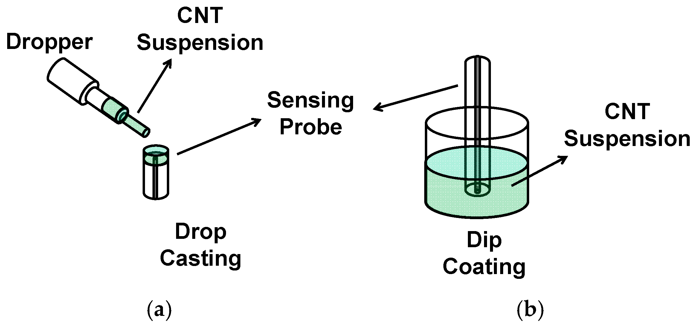
Drop casting and dip coating are two very similar deposition methods. Drop casting involves the dispersion of a solution (or suspension) onto a substrate [25] while dip coating involves the dipping of a substrate into the solution (or suspension) and removing the substrate at a controlled rate [26,27]. Figure 2 illustrates the drop casting and dip coating of CNTs onto an optical fibre sensing probe. For drop casting (Figure 2a), a CNT suspension is dripped onto the sensing region of the optical fibre. In the case of dip coating (Figure 2b), the fibre segment is dipped into the CNT suspension for a period of time before being removed. To evaporate the liquid medium, the fabricated sensor is then either left to stand for a period of time or placed in an oven. The deposition process can be repeated until the desired thickness of the deposited CNTs can be obtained.
3.2. Langmuir-Blodgett (LB)
In this method, CNTs are first dispersed over a sub-phase as shown in Figure 3. The sub-phase is pressurized from opposite sides by means of moving barriers to give a solid phase where molecules are packed into a highly ordered array [28]. The sensing probe is then immersed in the solid phase and drawn at a fixed rate out of it. Pressure on the solid phase is maintained at all times through continuous pressure from the moving barriers. Monolayers of CNTs would be transferred onto the sensing probe when the fibre segment is drawn out. The number of transferred monolayers would depend on the number of times the process is carried out. This method of deposition has the advantage of high precision control over the thickness of the deposited CNTs [29,30,31].
3.3. Optical Deposition
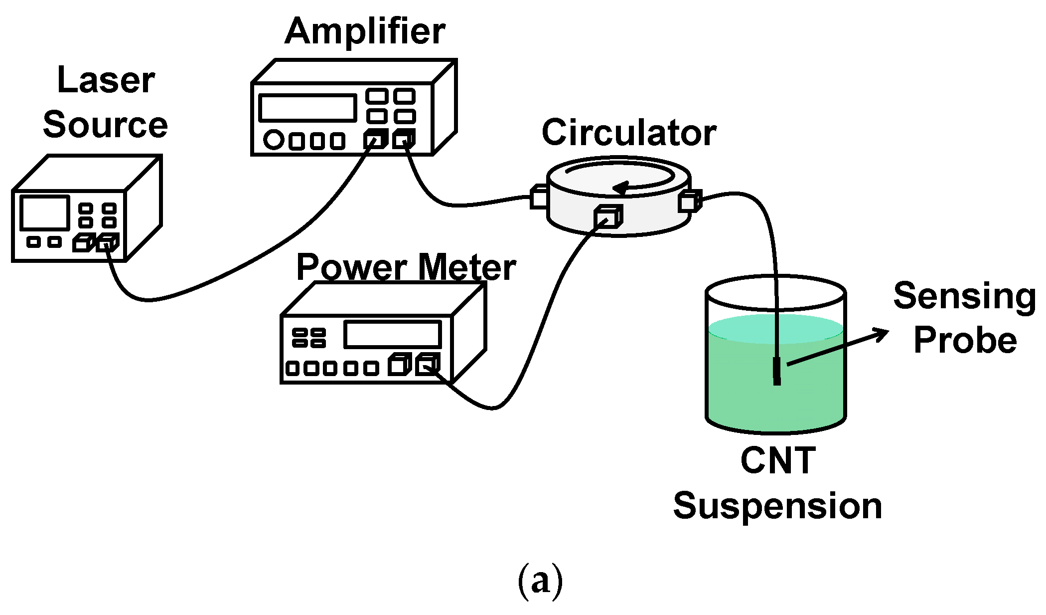
Optical deposition is a process where particulate matter can be deposited onto the surface of an optical fibre [32,33]. As shown in Figure 4a, light with a certain intensity is coupled into the fibre segment where CNTs are to be deposited. When immersed in a CNT suspension, the emitted light would result in the occurrence of four physical effects. These effects would affect the movement of CNTs as shown in Figure 4b, which uses the deposition of CNTs onto the end face of an optical fibre as an example. The first is the Gradient force where particles would move from a region of lower light intensity to a region of higher light intensity. The next effect would be the formation of convection currents generated due to the heating of the liquid medium. These induced currents would result in the upward movement of CNTs, towards the fibre end. The third, and the only force that acts against the deposition mechanism is the scattering force. This acts in the direction of propagation of the emitted beam and is dependant on the intensity of the input light. Thermophoresis, the last and the dominant effect, is the effect which results in the movement of particles down a temperature gradient [34] i.e., from the warm liquid to the cold fibre surface. As shown in Figure 4a, the back-reflected light is coupled into a power meter via a circulator (or coupler). The intensity of the light is continuously monitored and a large change in intensity would indicate that CNTs have adhered onto the surface of the optical fibre. The desired thickness of the deposited CNTs can, therefore, be obtained through control of the intensity of the input light as well as the duration of the deposition.
3.4. Spray Coating
Spray coating is another method for depositing CNTs onto a segment of an optical fibre [35,36,37]. As shown in Figure 5, the region to be deposited is held straight over a substrate (usually glass). A spray gun, which contains a small volume of the CNT suspension, is connected to a nitrogen gas supply set to a certain pressure, and directed at an angle to the fibre. A heating source directed at the dispersion path can be included to evaporate the liquid medium that exits the spray gun with the CNTs. The fibre has to be rotated over the course of the deposition to ensure that the CNTs are uniformly deposited. The thickness of the deposited CNTs can be observed from the substrate if conventional microscopy techniques are not available or suitable for direct observation for that of the optical fibre segment. As shown in Figure 5, the output ends of the fibre sensor can also be respectively connected to a source and detector, allowing for the monitoring of the spectral features throughout the deposition process.
4. Chemical Sensing Applications
In the last two decades, several CNT-deposited optical fibre sensing probes have been proposed for the detection of various chemicals. This section will briefly present some of these sensing probes. The reader should note that it is not the intention of this work to make performance comparisons between sensing probes and all quoted numerical values are meant to give an idea of the sensing characteristics of these sensors only.
In a series of works, Penza et al., Consales et al. and Cusano et al., demonstrated a sensing probe for the detection of various volatile organic compounds (VOCs) in the air [38,39,40,41,42,43], water [44] and hydrogen at cryogenic temperatures [45]. The sensing probe was fabricated by first depositing several monolayers of Cadmium Arachidate (CDA) onto the end-face of an optical fibre using the LB method. SWCNTs were then dispersed into chloroform and spread over a sub-phase of Cadmium Chloride and De-ionized water. The LB method was then used to deposit a few monolayers of SWCNTs onto the CDA coated optical fibre end to form the sensing probe. Several sensing probes with different numbers of monolayers were fabricated in this series of works. The sensing probes were exposed to various VOCs such as isopropanol (IPA), toluene and xylene, and their relative reflectance were obtained through an interrogation set up. In a gaseous medium, the sensing probes were able to detect changes in VOC concentrations within the range of 0 to 100 parts per million (ppm) and exhibited sensitivities of 0.5 × 10⁻³ ppm−1, 0.6 × 10⁻³ ppm−1, 1.3 × 10⁻³ ppm−1, 3.2 × 10⁻³ ppm−1, for Ethanol, IPA, Toluene and Xylene, respectively [43]. In an aqueous medium, a sensitivity of 6 × 10⁻⁴ ppm−1 was achieved for Toluene [44]. At cryogenic temperatures (~113 K), the sensing probe was also able to exhibit a response to a 1% increase in hydrogen [45].
Manivannan et al. demonstrated a sensing probe which was fabricated by dip coating a poly-methyl methacrylate (PMMA) optical fibre with part of its cladding removed in a suspension of SWCNTs and 1,2-dichlorobenzene [46]. Several sensing probes were fabricated, each with a different number of iterations for the dip coating process. The sensing probes were exposed to ammonia, ethanol and methanol vapours with concentrations ranging from 10 to 50 ppm and achieved respectively, sensitivities of 1.3 ΔI/ppm, 1.12 ΔI/ppm and 3.54 ΔI/ppm (ΔI is the change in intensity of the interrogated light).
Shivananju et al. [47] fabricated a sensing probe by first inscribing a fibre Bragg grating (FBG) into an optical fibre and etching the cladding region around the FBG to a diameter of ~4.5 µm. MWCNTs were then grown via chemical vapour deposition onto the etched region. The sensing probe was able to detect variations in humidity of the ambient environment with a sensitivity of 31 pm/%RH and 0.03 RH limit of detection (RH is the relative humidity).
Using the drop casting method, Shabaneh et al. deposited MWCNTs, that had been functionalized with nitric acid and dispersed in acetone, onto the end face of a multimode fibre [48]. Several sensing probes with different thickness of deposited MWCNTs were studied. This was done by using different concentrations of MWCNT suspensions during the deposition process. The sensing probes were further annealed in an oven to improve their adhesion onto the fibre surface. They were then exposed to aqueous ethanol with concentrations ranging from 5% to 80%. The best performing sensing probe achieved a sensitivity of 0.02%R/%C (R is the reflectance and C is the concentration of ethanol). Using the same deposition method, Batumalay et al. deposited a SWCNT polyethylene oxide (PEO) composite onto an etched plastic optical fibre [49]. The SWCNTs were first prepared by mixing 99% SWCNTs with sodium dodecyl sulfate and further refined in an ultrasonication and centrifugation process similar to that described in Section 3. The composite was then prepared through mixing the SWCNT solution with a PEO solution. The sensing probe was exposed to aqueous uric acid with concentrations ranging from 0 to 500 ppm. The sensing probe achieved a sensitivity of 0.0023 mV/%C.
Tan et al. spray coated a long period grating (LPG) [50] and a photonic crystal fibre interferometer (PCFI) [51] with CNTs dispersed in DMF. The sensing probes were used to detect variations in refractive indices (RIs) of various solutions. The RIs of each of these solutions were obtained through varying the concentration of glucose dissolved in a fixed concentration of deionised water. There was a nonlinear variation in intensity with RI for both sensing probes. For the CNT-deposited LPG, the sensitivity was reported to be 31 dB/RIU and 47 dB/RIU (RIU is a refractive index unit) for the RI ranges of 1.33–1.38 and 1.38–1.42, respectively. The achieved sensitivity for the CNT-deposited PCFI was 19.4 dB/RIU and 24.2 dB/RIU for the same RI ranges. Repeatability tests were also carried out for both sensing probes to show that there was minimal degradation in performance over time. A third sensing probe was fabricated through optical deposition of CNTs in DMF onto the end-face of a multimode fibre interferometer [52]. The sensing probe was similarly immersed in solutions of varying glucose concentrations and was able to demonstrate sensitivities of 35.9 dB/RIU and 157.9 dB/RIU for the RI ranges of 1.33–1.40 and 1.40–1.45, respectively.
Allsop et al. demonstrated a sensing probe for the specific detection of carbon dioxide (CO2) at room temperature [53]. The sensing probe was fabricated by first sputtering a series of coatings (Germanium, Silicon Dioxide and Platinum) onto a D-shaped fibre (fabricated through mechanical lapping of a single-mode fibre). The sputtered region was then exposed to an ultraviolet laser over a phase mask which resulted in the formation of surface relief structures. Purified SWCNTs and Polyvinyl Pyrrolidone were added to N-methyl-2-pyrrolidone and ultrasonicated and centrifuged. The SWCNTs were then deposited onto the coated D-shaped fibre via dip coating. The group demonstrated the specificity of their sensing probe to CO2 and yielded index sensitivities in excess of 3 × 10⁴ nm/RIU and 4.2 × 10⁴ dB/RIU for atmospheric conditions approaching that of 100% CO2 concentration.
5. Conclusions
The unique material properties of carbon nanotubes (CNTs) have allowed for the extension of their applications into the field of chemical sensing. This paper has highlighted one of the ways this has been done, which is the integration of CNTs with various optical fibre sensing probes. The various deposition methods for their fabrication, general operating principle of these sensing probes and some demonstrated examples have been described. The interested reader would notice that there is a lot more work that can be accomplished in this area. For example, the functionalizing of CNTs for selective sensing and the enhancement of deposition methods (for better sensitivity, reproducibility and repeatability of sensing behaviour) for integration with optical fibres is still a significant challenge. Significant breakthroughs in these areas would contribute largely to the development and expansion of this field.
Funding
This work was funded by Temasek Laboratories @ NTU.
Acknowledgments
The author would like to acknowledge the support provided by Temasek Laboratories, OPTIMUS, COEB and COFT of NTU, Singapore.
Conflicts of Interest
The author declares no conflicts of interest.
References
- Iijima, S. Helical microtubules of graphitic carbon. Nature 1991, 354, 56–58. [Google Scholar] [CrossRef]
- Iijima, S.; Ichihashi, T. Single-shell carbon nanotubes of 1-nm diameter. Nature 1993, 363, 603–605. [Google Scholar] [CrossRef]
- Allen, M.J.; Tung, V.C.; Kaner, R.B. Honeycomb carbon: A review of graphene. Chem. Rev. 2009, 110, 132–145. [Google Scholar] [CrossRef] [PubMed]
- Yamashita, S. A tutorial on nonlinear photonic applications of carbon nanotube and graphene. J. Lightw. Technol. 2012, 30, 427–447. [Google Scholar] [CrossRef]
- Wang, X.; Li, Q.; Xie, J.; Jin, Z.; Wang, J.; Li, Y.; Jiang, K.; Fan, S. Fabrication of ultralong and electrically uniform single-walled carbon nanotubes on clean substrates. Nano Lett. 2009, 9, 3137–3141. [Google Scholar] [CrossRef] [PubMed]
- Zhang, R.; Zhang, Y.; Zhang, Q.; Xie, H.; Qian, W.; Wei, F. Growth of half-meter long carbon nanotubes based on Schulz-Flory distribution. ACS Nano 2013, 7, 6156–6161. [Google Scholar] [CrossRef] [PubMed]
- Yu, M.F.; Files, B.S.; Arepalli, S.; Ruoff, R.S. Tensile loading of ropes of single wall carbon nanotubes and their mechanical properties. Phys. Rev. Lett. 2000, 84, 5552–5555. [Google Scholar] [CrossRef] [PubMed]
- Collins, P.G.; Avouris, P. Nanotubes for electronics. Sci. Am. 2000, 283, 62–69. [Google Scholar] [CrossRef] [PubMed]
- Balandin, A.A. Thermal properties of graphene and nanostructured carbon materials. Nat. Mater. 2011, 10, 569–581. [Google Scholar] [CrossRef] [PubMed] [Green Version]
- Tran, T.Q.; Headrick, R.J.; Bengio, E.A.; Myint, S.M.; Khoshnevis, H.; Jamali, V.; Duong, H.M.; Pasquali, M. Purification and Dissolution of Carbon Nanotube Fibres Spun from Floating Catalyst Method. ACS Appl. Mater. Interfaces 2017, 9, 37112–37119. [Google Scholar] [CrossRef] [PubMed]
- Khoshnevis, H.; Tran, T.Q.; Mint, S.M.; Zadhoush, A.; Duong, H.M.; Youssefi, M. Effect of alignment and packing density on the stress relaxation process of carbon nanotube fibres spun from floating catalyst chemical vapor deposition method. Colloid Surf. A 2018, 558, 570–578. [Google Scholar] [CrossRef]
- Zaporotskova, I.V.; Boroznina, N.P.; Parkhomenko, Y.N.; Kozhitiv, L.V. Carbon nanotubes: sensor properites. A review. Mod. Electron. Mater. 2016, 2, 95–105. [Google Scholar] [CrossRef]
- Meyer, M.S.; Eesley, G.L. Optical fibre refractometer. Rev. Sci. Instrum. 1987, 58, 2047–2048. [Google Scholar] [CrossRef]
- Othonos, A.; Kalli, K. Fibre Bragg Gratings: Fundamentals and Applications in Telecommunications and Sensing; Artech House: Norwood, MA, USA, 1999. [Google Scholar]
- Kersey, A.D.; Davis, M.A.; Patrick, H.J.; LeBlanc, M.; Koo, K.P.; Askins, C.G.; Putnam, M.A.; Friebele, E.J. Fibre grating sensors. J. Lightw. Technol. 1997, 15, 1442–1463. [Google Scholar] [CrossRef]
- Vengsarkar, A.M.; Lemaire, P.J.; Judkins, J.B.; Bhatia, V.; Erdogan, T.; Sipe, J.E. Long-period fibre gratings as band-rejection filters. J. Lightw. Technol. 1996, 14, 58–65. [Google Scholar] [CrossRef]
- Bhatia, V.; Vengsarkar, A.M. Optical fibre long-period grating sensors. Opt. Lett. 1996, 21, 692–694. [Google Scholar] [CrossRef] [PubMed]
- Kieu, K.Q.; Mansuripur, M. Biconical fibre taper sensors. IEEE Photonics Technol. Lett. 2006, 18, 2239–2241. [Google Scholar] [CrossRef]
- Lee, B.H.; Kim, Y.H.; Park, K.S.; Eom, J.B.; Kim, M.J.; Rho, B.S.; Choi, H.Y. Interferometric fibre optic sensors. Sensors 2012, 12, 2467–2486. [Google Scholar] [CrossRef] [PubMed]
- Jha, R.; Villatoro, J.; Badenes, G. Ultrastable in reflection photonic crystal fibre modal interferometer for accurate refractive index sensing. Appl. Phys. Lett. 2008, 93, 1911061–1911063. [Google Scholar] [CrossRef]
- Silva, S.; Frazão, O.; Santos, J.L.; Malcata, F.X. A reflective optical fibre refractometer based on multimode interference. Sens. Actuators B 2012, 161, 88–92. [Google Scholar] [CrossRef]
- Gupta, B.D.; Dodeja, H.; Tomar, A.K. Fibre optic evanescent field absorption sensor based on a U-shaped probe. Opt. Quantum Electron. 1996, 28, 1629–1639. [Google Scholar] [CrossRef]
- Banerjee, A.; Mukherjee, S.; Verma, R.K.; Jana, B.; Khan, T.K.; Chakroborty, M.; Das, R.; Biswas, S.; Saxena, A.; Singh, V.; et al. Fibre optic sensing of liquid refractive index. Sens. Actuators B 2007, 123, 594–605. [Google Scholar] [CrossRef]
- Margulis, V.A.; Gaiduk, E.A. Nature of near-infrared absorption in single-wall carbon nanotubes. Phys. Lett. A 2001, 281, 52–58. [Google Scholar] [CrossRef]
- Sreekumar, T.V.; Liu, T.; Kumar, S. Single-wall carbon nanotube films. Chem. Mater. 2002, 15, 175–178. [Google Scholar] [CrossRef]
- Spotnitz, M.E.; Ryan, D.; Stone, H.A. Dip coating for the alignment of carbon nanotubes on curved surfaces. J. Mater. Chem. 2004, 14, 1299–1302. [Google Scholar] [CrossRef]
- Jang, E.Y.; Kang, T.J.; Im, H.W.; Kim, D.W.; Kim, Y.H. Single-walled carbon-nanotube networks on large-area glass substrate by the dip-coating method. Small 2008, 4, 2255–2261. [Google Scholar] [CrossRef] [PubMed]
- Krstic, V.; Duesberg, G.S.; Muster, J.; Burghard, M.; Roth, S. Langmuir-Blodgett films of matrix-diluted single-walled carbon nanotubes. Chem. Mater. 1998, 10, 2338–2340. [Google Scholar] [CrossRef]
- Guo, Y.; Wu, J.; Zhang, Y. Manipulation of single-wall carbon nanotubes into aligned molecular layers. Chem. Phys. Lett. 2002, 362, 314–318. [Google Scholar] [CrossRef]
- Kim, Y.; Minami, N.; Zhu, W.; Kazaoui, S.; Azumi, R.; Matsumoto, M. Langmuir-Blodgett films of single-wall carbon nanotubes: layer-by-layer deposition and in-plane orientation of tubes. Jpn. J. Appl. Phys. 2003, 42, 7629–7634. [Google Scholar] [CrossRef]
- Li, X.; Zhang, L.; Wang, X.; Shimoyama, I.; Sun, X.; Seo, W.S.; Dai, H. Langmuir-Blodgett assembly of densely aligned single-walled carbon nanotubes from bulk materials. J. Am. Chem. Soc. 2007, 129, 4890–4891. [Google Scholar] [CrossRef] [PubMed]
- Nicholson, J.W.; Windeler, R.S.; DiGiovanni, D.J. Optically driven deposition of single-walled carbon-nanotube saturable absorbers on optical fibre end-faces. Opt. Express 2007, 15, 9176–9183. [Google Scholar] [CrossRef] [PubMed]
- Kashiwagi, K.; Yamashita, S.; Set, S.Y. Optically Manipulated Deposition of Carbon Nanotubes onto Optical Fibre End. Jpn. J. Appl. Phys. 2007, 46, 988–990. [Google Scholar] [CrossRef]
- McNab, G.S.; Meisen, A. Thermophoresis in liquids. J. Colloid Interfaces Sci. 1973, 44, 339–346. [Google Scholar] [CrossRef]
- Set, S.Y.; Yaguchi, H.; Tanaka, Y.; Jablonski, M. Laser mode locking using a saturable absorber incorporating carbon nanotubes. J. Lightw. Technol. 2004, 22, 51–56. [Google Scholar] [CrossRef]
- Song, Y.W.; Morimune, K.; Set, S.Y.; Yamashita, S. Polarization insensitive all-fibre mode-lockers functioned by carbon nanotubes deposited onto tapered fibres. Appl. Phys. Lett. 2007, 90, 0211011–0211013. [Google Scholar] [CrossRef]
- Chow, K.K.; Yamashita, S.; Set, S.Y. Four-wave-mixing-based wavelength conversion using a single-walled carbon-nanotube-deposited planar lightwave circuit waveguide. Opt. Lett. 2010, 35, 2070–2072. [Google Scholar] [CrossRef] [PubMed]
- Penza, M.; Cassano, G.; Aversa, P.; Antolini, F.; Cusano, A.; Cutolo, A.; Giordano, M.; Nicolais, L. Alcohol detection using carbon nanotubes acoustic and optical sensors. Appl. Phys. Lett. 2004, 85, 2379–2381. [Google Scholar] [CrossRef]
- Penza, M.; Cassano, G.; Aversa, P.; Cusano, A.; Consales, M.; Giordano, M.; Nicolais, L. Carbon nanotube acoustic and optical sensors for volatile organic compound detection. Nanotechnology 2005, 16, 2536. [Google Scholar] [CrossRef]
- Penza, M.; Cassano, G.; Aversa, P.; Cusano, A.; Consales, M.; Giordano, M.; Nicolais, L. Acoustic and Optical VOCs Sensors incorporating carbon nanotubes. IEEE Sens. J. 2006, 6, 867–875. [Google Scholar] [CrossRef]
- Consales, M.; campopiano, S.; Cutolo, A.; Penza, M.; Aversa, P.; Cassano, G.; Giordano, M.; Cusano, A. Carbon nanotubes thin films fibre optic and acoustic VOCs sensors: performance analysis. Sens. Actuators B Chem. 2006, 118, 232–242. [Google Scholar] [CrossRef]
- Consales, M.; Cutolo, A.; Penza, M.; Aversa, P.; Cassano, G.; Giordano, M.; Cusano, A. Carbon nanotubes coated acoustic and optical VOCs sensors: Towards the tailoring of the sensing performances. IEEE Trans. Nanotechnol. 2007, 6, 601–612. [Google Scholar] [CrossRef]
- Consales, M.; Crescitelli, A.; Penza, M.; Aversa, P.; Veneri, P.D.; Giordano, M.; Cusano, A. SWCNT nano-composite optical sensors for VOC and gas trace detection. Sens. Actuators B Chem. 2009, 138, 351–361. [Google Scholar] [CrossRef]
- Consales, M.; Crescitelli, A.; Campopiano, S.; Cutolo, A.; Penza, M.; Aversa, P.; Giordano, M.; Cusano, A. Chemical detection in water by single-walled carbon nanotubes-based optical fibre sensors. IEEE Sens. J. 2007, 7, 1004–1005. [Google Scholar] [CrossRef]
- Cusano, A.; Consales, M.; Cutolo, A.; Penza, M.; Aversa, P.; Giordano, M.; Guemes, A. Optical probes based on optical fibres and single-walled carbon nanotubes for hydrogen detection at cryogenic temperatures. Appl. Phys. Lett. 2006, 89. [Google Scholar] [CrossRef]
- Mannivannan, S.; Saranya, A.M.; Renganathan, B.; Sastikumar, D.; Gobi, G.; Park, K.C. Single-walled carbon nanotubes wrapped poly-methyl methacrylate fibre optic sensor for ammonia, ethanol and methanol vapors at room temperature. Sens. Actuators B Chem. 2012, 171, 634–638. [Google Scholar] [CrossRef]
- Shivananju, B.N.; Yamadagni, S.; Fazuldeen, R.; Kumar, A.K.S.; Nithin, S.P.; Varma, M.M.; Asokan, S. Highly Sensitive Carbon Nanotubes Coated Etched Fibre Bragg Grating Sensor for Humidity Sensing. IEEE Sens. J. 2014, 14, 2615–2619. [Google Scholar] [CrossRef]
- Shabaneh, A.A.; Girei, S.H.; Arasu, P.T.; Rashid, S.A.; Yunusa, Z.; Mahdi, M.A.; Paiman, S.; Ahmad, M.Z.; Yaacob, M.H. Reflectance response of optical fibre coated with carbon nanotubes for aqueous ethanol sensing. IEEE Photonics J. 2014, 6, 68029101–680291010. [Google Scholar] [CrossRef]
- Batumalay, M.; Ahmad, F.; Lokman, A.; Jasim, A.A.; Harun, S.W.; Ahmad, H. Tapered plastic optical fibre coated with single wall carbon nanotubes polyethylene oxide composite for measurement of uric acid concentration. Sens. Rev. 2014, 34, 75–79. [Google Scholar] [CrossRef]
- Tan, Y.C.; Ji, W.B.; Mamidala, V.; Chow, K.K.; Tjin, S.C. Carbon-nanotube-deposited long period fibre grating for continuous refractive index sensor applications. Sens. Actuators B Chem. 2014, 196, 260–264. [Google Scholar] [CrossRef]
- Tan, Y.C.; Tou, Z.Q.; Mamidala, V.; Chow, K.K.; Chan, C.C. Continuous refractive index sensing based on carbon-nanotube-deposited photonic crystal fibres. Sens. Actuators B Chem. 2014, 202, 1097–1102. [Google Scholar] [CrossRef]
- Tan, Y.C.; Huang, J.Y.; Chow, K.K. Continuous Refractive Index Sensing based on Carbon-nanotube-deposited joint single-mode multi-mode fibre segment. In Proceedings of the 2015 IEEE Photonics Conference, Reston, VA, USA, 4–8 October 2015. [Google Scholar]
- Allsop, T.; Arif, R.; Neal, R.; Kalli, K.; Kundrát, V.; Rozhin, A.; Culverhouse, P.; Webb, D.J. Photonic gas sensors exploiting directly the optical properties of hybrid carbon nanotube localized surface plasmon structures. Light Sci. Appl. 2016, 5, e16036. [Google Scholar] [CrossRef] [PubMed]
Figure 1.
(a) Examples of various optical fibre sensing probes. Diagrams show a fibre grating (top left), tapered fibre (top right), optical fibre interferometer (bottom left) and a cladding-removed optical fibre (b) Examples of how carbon nanotubes (CNTs) can be deposited onto various optical fibre sensing probes. The diagram on the left shows the deposition of CNTs onto the surface of a fibre grating while that on the right shows the deposition of CNTs onto the end-face of an optical fibre.

Figure 2.
Illustration of the drop casting (a) and dip coating process (b) for the deposition of CNTs onto an optical fibre sensing probe.
Figure 2.
Illustration of the drop casting (a) and dip coating process (b) for the deposition of CNTs onto an optical fibre sensing probe.

Figure 3.
Schematic of the Langmuir-Blodgett deposition process.

Figure 4.
(a) Schematic of the experimental set up for optical deposition of CNTs onto an optical fibre sensing probe; (b) Illustration of the various physical effects which would result in the deposition of CNTs onto the end-face of an optical fibre.
Figure 4.
(a) Schematic of the experimental set up for optical deposition of CNTs onto an optical fibre sensing probe; (b) Illustration of the various physical effects which would result in the deposition of CNTs onto the end-face of an optical fibre.


Figure 5.
Schematic of the experimental set up for spray coating of CNTs onto an optical fibre sensing probe.
Figure 5.
Schematic of the experimental set up for spray coating of CNTs onto an optical fibre sensing probe.

© 2018 by the author. Licensee MDPI, Basel, Switzerland. This article is an open access article distributed under the terms and conditions of the Creative Commons Attribution (CC BY) license (http://creativecommons.org/licenses/by/4.0/).
Share and Cite
MDPI and ACS Style
Tan, Y.C. Chemical Sensing Applications of Carbon Nanotube-Deposited Optical Fibre Sensors. Chemosensors 2018, 6, 55. https://doi.org/10.3390/chemosensors6040055
AMA Style
Tan YC. Chemical Sensing Applications of Carbon Nanotube-Deposited Optical Fibre Sensors. Chemosensors. 2018; 6(4):55. https://doi.org/10.3390/chemosensors6040055
Chicago/Turabian StyleTan, Yung Chuen. 2018. "Chemical Sensing Applications of Carbon Nanotube-Deposited Optical Fibre Sensors" Chemosensors 6, no. 4: 55. https://doi.org/10.3390/chemosensors6040055
Note that from the first issue of 2016, this journal uses article numbers instead of page numbers. See further details here.