
Recent Advances in Membrane-Based Biogas and Biohydrogen Upgrading
by
 , , , and
Cenit Soto
1,2,
Laura Palacio
1,2 ,
,
Raúl Muñoz
2,3,
Pedro Prádanos
1,2,* and
and
Antonio Hernandez
1,2,* 
1
Surfaces and Porous Materials (SMAP), Associated Research Unit to CSIC, Facultad de Ciencias, University of Valladolid, Paseo Belén 7, E-47011 Valladolid, Spain
2
Institute of Sustainable Processes (ISP), Dr. Mergelina s/n, 47011 Valladolid, Spain
3
Department of Chemical Engineering and Environmental Technology, School of Industrial Engineering, University of Valladolid, Dr. Mergelina s/n, 47011 Valladolid, Spain
*
Authors to whom correspondence should be addressed.
Processes 2022, 10(10), 1918; https://doi.org/10.3390/pr10101918
Submission received: 29 August 2022
/
Revised: 15 September 2022
/
Accepted: 18 September 2022
/
Published: 22 September 2022
(This article belongs to the Special Issue New Frontiers in Anaerobic Digestion (AD) Processes)
Abstract
:Biogas and biohydrogen, due to their renewable nature and zero carbon footprint, are considered two of the gaseous biofuels that will replace conventional fossil fuels. Biogas from anaerobic digestion must be purified and converted into high-quality biomethane prior to use as a vehicle fuel or injection into natural gas networks. Likewise, the enrichment of biohydrogen from dark fermentation requires the removal of CO2, which is the main pollutant of this new gaseous biofuel. Currently, the removal of CO2 from both biogas and biohydrogen is carried out by means of physical/chemical technologies, which exhibit high operating costs and corrosion problems. Biological technologies for CO2 removal from biogas, such as photosynthetic enrichment and hydrogenotrophic enrichment, are still in an experimental development phase. In this context, membrane separation has emerged as the only physical/chemical technology with the potential to improve the performance of CO2 separation from both biogas and biohydrogen, and to reduce investment and operating costs, as a result of the recent advances in the field of nanotechnology and materials science. This review will focus on the fundamentals, potential and limitations of CO2 and H2 membrane separation technologies. The latest advances on membrane materials for biogas and biohydrogen purification will be systematically reviewed.
1. Biogas and Biohydrogen as Green Energy Vectors
Biogas is produced via Anaerobic Digestion (AD) of residual biomass from diverse origins such as urban solid waste, livestock waste, agricultural waste, and wastewater. AD is a biological process (based on the action of micro-organisms) able to convert this residual biomass, by means of oxidations and reductions of organic carbon, to carbon dioxide and methane (CO2 and CH4, respectively) in the absence of oxygen [1,2]. This biological conversion is carried out through a sequence of hydrolysis, acidogenesis, acetogenesis and methanogenesis steps in an anaerobic digester [3]. Biogas is typically composed of CH4 and CO2 in a concentration range of 45–85% and 25–50%, respectively, and minor concentrations of other components such as H2O (5–10%), N2 (~0–1%), O2 (~0–0.5%), H2S (0–10,000 ppm), NH3 (0–100 ppm) and hydrocarbons (0–200 mg Nm−3) [4,5]. The biogas produced by AD represents an excellent alternative to fossil-based energy vectors [2], since biogas can be employed for the production of electricity, steam and heat, as a feedstock in fuel cells, as a green substitute of natural gas for domestic and industrial use or as a vehicle fuel [1]. The contribution of biogas in the European Union could account for 10% of the natural gas demand by 2030 and up to 30–40% by 2050.
Based on the latest report of the World Biogas Association [6], 50 million micro-scale digesters generating biogas for cooking or heating were in operation, mainly in China (42 million) and India (4.9 million). On the other hand, 18,774 large-scale plants devoted to generating 11 GW (a biomethane plant produces an average of 36 GWh per year) of electricity were in operation in 2021 in Europe, Germany being the leader in the European market with 11,279 in 2020 plants (140 plants/1 Mio capita), followed by Italy (1666 in 2020) and France (833 new plants in 2020) [4,7]. China with 6972 large scale digesters and the USA with 2200 AD plants in 2015 represented the second and third largest biogas producer in the world, respectively. The global electricity generation from biogas increased by 90% in six years (from 46,108 GWh in 2010 to 87,500 GWh in 2016) and by 11.5 % from 2016 to 2020 (from 87,500 GWh in 2016 to 96,565 GWh in 2020) [6,8].
Biogas can be purified and converted into a high-quality biomethane via three sequential processes: desulfurization (elimination of the H2S), CO2 removal and biomethane polishing (removal of the minor biogas contaminants) [9]. The European EN-16723 Standard for biomethane introduction into natural gas networks (UNE-EN 16723-1-2016) and automotive/vehicle fuel (UNE-EN 16723-2-2017) requires an effective cleaning of biogas. This UNE-EN 16723-1-2016 standard has resulted in a specific Spanish standard for biomethane injection into the natural gas grid, requiring a minimum methane content of 90% and a maximum CO2 content of 2% (v/v) [10]. In 2017, the number of biogas upgrading plants in the world accounted for 700 plants, Europe being the leading region with 540 upgrading plants in operation.
At the end of 2020 (the most recent data available), 880 biogas upgrading plants with a production capacity of 2.43 billion m3 were in operation in Europe (161 additional plants relative to 2019) [4,7]. By 2021 the increase in the number of biomethane plants is expected to be even faster since 115 plants have started operation by August 2021 [7].
On the other hand, biologically produced hydrogen (commonly referred to as biohydrogen) generated via Dark Fermentation (DF) represents another alternative bioenergy source [11]. Biohydrogen (bioH2) has the potential to become a relevant H2 generation platform for the creation of a green economy [12]. In this context, hydrogen has multiple advantages as a clean energy vector such as: (i) the combustion of H2 gas can be pollution-free in fuel cells, (ii) its energy efficiency in H2 fuel cells is approx. 50% higher than that of gasoline, (iii) it has a specific energy content of 122 kJ/g (~2.75-fold larger than conventional fossil fuels), (iv) its conversion efficiency to electricity could be doubled using fuel cells instead of gas turbines, and finally (v) it can be stored as a metal hydride.
Dark fermentation is based on hydrogen and carbon dioxide (CO2) production via anaerobic bacteria [13] and/or algae growing in the absence of light and with high carbohydrate content as substrate [14,15]. The biohydrogen produced is mainly composed of hydrogen (40–60%) and carbon dioxide (47–60%) with traces of methane and H2S [16,17]. Currently, only 1% of hydrogen is produced from biomass [15]. This fact is probably due to the relatively late research on bioH2 production by dark fermentation, where research is still conducted at a laboratory scale with a limited number of experiments at pilot scale [18]. Despite the fact that the H2 yield from dark fermentation is higher than that of other processes, the main disadvantage of the gas generated during dark fermentation is its low hydrogen concentration (40–60%; v/v) [19], which hinders its direct use in fuel cells for electricity generation (where the purity of hydrogen is crucial to achieve high energy yields) [16]. Therefore, it is crucial to separate H2 from the multiple gas by-products from DF, mainly CO2, in order to obtain purified hydrogen. For instance, a hydrogen content of 73% can be obtained in a two-step gas membrane separation module [19].
The sustained use of non-polluting renewable energy vector such as biogas and bioH2 is required to reduce the demand and dependence from fossil fuels [20]. Based on the International Energy Agency, the share of renewable and low-carbon transport fuels should increase up to 6.8% in 2030 in Europe, with advanced biofuels representing at least 3.6% of the total fuel consumption. The development of low footprint and cost technologies for the conversion of biogas to a purified biomethane and bioH2 to pure H2 is essential to guarantee the competitiveness of these green gas vectors as an energy source.
2. Biogas and Biohydrogen Purification with Membrane Technology
Nowadays, there are two main types of technologies for biogas purification, physicochemical and biological methods, while bioH2 purification is only performed by physicochemical methods. Physicochemical technologies exhibit high energy and chemical demand, and therefore they present large operating costs and environmental impacts. As an example, this section will only focus on CO2 removal technologies.
Pressure swing adsorption (PSA), cryogenic CO2 separation, scrubbing with H2O, chemical solutions or organic solvents, and membrane separation, dominate the biogas upgrading market nowadays [21], while cryogenic distillation, PSA and membrane separation are the most popular processes for H2 purification at commercial scale [22,23,24].
Separation of gas mixtures through membranes has become a relevant unitary operation for the recovery of valuable gases and mitigation of atmospheric pollution, which offers several advantages over conventional gas separation methods [25]. Indeed, Membrane Separation (MS) is considered nowadays the most promising gas purification technology. Membrane separation relies on the interaction (physical or chemical) of certain gases with the membrane material [26]. The membranes used are selective physical barriers with certain components that permeate across them [27]. Gas separation by membrane technology is characterized by selectivity properties and flux, which supports a functional transport of the target gases across the barrier (permeability). This technology presents a low energy consumption, a simple operation, cost effectiveness, smaller footprint, a negligible chemical consumption and low environmental impacts [28,29]. The potential of MS to achieve high efficiencies of gas separation foster their use in different industrial applications including refineries and chemical industries, and recent advances in material science render MS a competitive technology [30]. The lifetime of commercial membranes account for 5–10 years [31]. Today, the use of membranes in industry includes the separation of N2 or O2 from air, separation of H2 from gases such as CH4, separation of CH4 from biogas, separation of H2S and CO2 from natural gas, etc. The use of membranes in separation processes is rapidly growing, especially in Europe (Figure 1). Among the available technologies for the purification of biogas to biomethane, membrane separation is currently the most widely used technology (39%), followed by water scrubbing (22%) and chemical scrubbing (18%). Pressure swing adsorption (12%), cryogenic separation (1%) and physical washing (1%) complete the market share (with the exception of 7% of European biomethane plants, with no data available in the EBA database) [7]. For instance, Baker (2002), calculated that the market share of membrane gas separation processes in 2020 would be five times higher than that of year 2000 [32]. Indeed, the market share of MS for biogas upgrading application has increased from 10% in 2012 to 25% in 2017 [33]. Likewise, MS has grown exponentially since the initial commercial application of Prism membranes by Permea (Monsanto) for H2 separation from the off-gas stream of NH3 production plants [26].
A detailed economic study of the total costs of biogas purification is a difficult task nowadays due to the large number of parameters to be considered. However, Miltner and co-workers (2017) have published some general estimates and a comparison of the most common physicochemical technologies such as pressurized water scrubbing, amine scrubbing, pressure swing adsorption and gas permeation. This study included investment costs (15 years’ depreciation), plant reliability of 98%, operational consumptions in terms of electricity and consumables (electricity price 15 €ct/kWh), as well as maintenance and overhaul (without engineering costs, taxes and revenues). Thus, the costs for an installation with a capacity of 250 m3 STP/h are in the range of 25 €ct/m3 STP, while these costs drop below 15 €ct/m3 STP for capacities above 2000 m3 STP/h. This work concluded that gas permeation is slightly more advantageous for sizes below 1000 m3 STP/h. Overall, small-scale biogas upgrading entails higher capital and operational costs [34].
Ideally, membrane materials for gas separation should exhibit a high selectivity and big fluxes, excellent chemical, mechanical and thermal stability, a defect-free production and be cost effective. Membranes are classified according to the type of material, configuration, structure, composition, support material and industrial reactions, among others (Figure 2) [35,36,37]. Four kinds of membranes are typically proposed for development and commercialization in hydrogen purification: (i) polymeric membranes (organic), (ii) porous membranes (ceramic, carbon, metal) (iii) dense metal membranes and (iv) ion conductive membranes, the last three also referred to as inorganic membranes [27]. In this context, dense-metal membranes and polymeric have experienced the largest advances in terms of scale-up [38]. The most commonly used polymeric membranes for gas separation are nonporous membranes, which are classified as glassy or rubbery. Of them, glassy polymers are most typically used for gas separation applications. These polymers include polysulfones (PSF), polycarbonates (PC) and polyimides (PI), which are often employed for the separation of H2/CH4, H2/N2 and O2/N2 [39]. On the other hand, membranes can be configured as hollow fibers, capillaries, flat sheets and tubular and can be installed in a suitable membrane module. The most commonly used modules are pleated cartridges, tubular and capillary, hollow-fiber and plate-and-frame and spiral-wound systems [40].
H2 separation was one of the pioneered applications in gas separation membranes, DuPont (E. I. du Pont de Nemours and Co., Wilmington, DE, USA) being the pioneer in manufacturing small-diameter hollow-fiber membranes. Due to the limited productivity (or permeance) of these membranes and their high cost, Monsanto Co. (Monsanto Company, St. Louis, MO, USA) developed polysulfone hollow-fiber membranes, which considerably increased the transport through the fibers, and consequently were successfully implemented at industrial-scale for hydrogen recovery from ammonia purge gases [41]. Then, Separex Corp (Champigneulles, France) developed Separex® spiral-wound cellulose acetate membranes (including separations for natural gas and dehydration [41] providing better performance than hollow fiber membranes due to their high resistance of hydrogen impurities [42]. Polymeric membranes, especially polyimides, have been employed to separate hydrogen from gaseous mixtures (N2, CO and hydrocarbons) based on their economic viability, easy processibility and satisfactory thermal stability (350–450 °C) [43]. Polyimide membranes with excellent heat resistances were introduced by Ube in Japan (Ube Industries, Ltd., Tokyo, Japan), and the refinery at Seibu Oils (Seibu Oil Company Limited, Onoba, Japan) was the first facility to apply them commercially [41]. Commercial membrane systems provide a H2 purity of 90–95% during hydrogen purification with a moderate recovery of 85–90% [44].
At the beginning of the 1990s, gas mixture separation membranes with a poor recovery of methane and low selectivity were installed for the upgrading of landfill biogas [45]. In 2007, Air Liquide MedalTM further developed and tested new selective membranes combining high CH4 recoveries with high CH4 concentrations.
Today, membrane-based biogas upgrading can provide methane concentrations of 97–98% in the biomethane with a concomitant methane recovery above 98%, based on the high permeabilities of CO2 in commercial membrane materials. The permeation rate mainly depends on the molecular size of the gas components and on the membrane construction material [46]. Membrane-based biogas upgrading at commercial scale is carried out at 6–20 bar, which entails energy consumption of 0.18–0.20 kWh/Nm3 of raw biogas or 0.14–0.26 kWh/Nm3 of biomethane [9].
In this regard, despite polymeric membranes having consistently demonstrated promising results and being commercially available at large-scale for hydrogen and biogas purification, their use is limited to 8–9 polymeric materials (e.g., cellulose acetate, polyimides, perfluoropolymer etc.) [47,48]. Therefore, further research in the field of material science needs to be conducted to achieve new membranes with superior gas separation properties: higher permeability, selectivity and stability (mainly restricted plasticization) [47].
3. Fundamentals of Membrane-Based Gas Separation
The membrane gas separation process is based on the separation of gases by selective permeation of one or more gaseous components through a thin membrane (porous or dense membrane) [49]. The separation potential of the membrane is governed by its transport properties of the components of a mixture. This transport rate is in turn dictated by the permeability and selectivity of the membrane material and its driving force [38].
Gas separation takes place according to the morphology of the membrane materials and can be based on three transport mechanisms depending on the porous size: solution-diffusion, molecular sieve and Knudsen diffusion (Figure 3). In this context, the transport of gases by Knudsen diffusion takes place in porous membranes (pore diameter in the range of 50–100 Å), with smaller pore size than the gas molecules. In this mechanism, gas molecules interact more frequently with the pore walls, colliding with each other, allowing diffusion of lighter molecules to occur through the pores. The molecular sieving mechanism, with pore size between 3.0–5.2 Å, is based on the size exclusion of gas molecules, leading to the separation of gas molecules of different kinetic sizes. Indeed, the pores only allow the passage of molecules smaller than that size, preventing the passage of larger ones [26,29].
Gas transport in non-porous dense polymeric membranes is most commonly described by solution-diffusion mechanisms (used exclusively in current commercial devices), which allows gases to pass through the membrane free volume units and consists of three steps [50]: (i) sorption in upstream side; (ii) diffusion through the membrane and (iii) desorption at the downstream side. Figure 4 shows a schematic overview of mass transfer by solution-diffusion, where gas molecules sorb into the high-pressure face of the membrane, then diffuse through along the membrane and later desorb from the low-pressure face of the membrane [51]. This mechanism of solution-diffusion is determined by the occurrence of differences in the thermodynamic activities at the upstream and downstream faces of the membrane, and the interacting force working among the gas molecules, which depends on the membrane components and the permeate molecules [52].
A key parameter to evaluate membrane transport properties is the Permeability coefficient (P), which refers to the gas flux across a membrane considering the membrane thickness and pressure gradient (pi,0-pi,l) through the membrane (Equation (1)).
where Ni is molar flux of a gas component i through the membrane, l is the membrane thickness and ∆p is the pressure gradient, calculates as the difference between pi,0 (the upstream pressure) and pi,l (the downstream pressure) [53].
The Permeability coefficient ranges from 10−4 to 104 Barrer as a function of the gas component and the polymer structure [52]. Permeability coefficients are expressed in mol (m2·s·Pa) in the international system of units. However, P is typically given in Barrer, where .
The solution-diffusion model considers that the conditions of equilibrium between sorption and desorption are maintained. In this context, a solubility coefficient, Si, is introduced, which is the ratio between the concentration of gas component dissolved in the membrane material, Ci, and the pressure of the gas, pi, in contact with the polymer (Equation (2)). The solubility of a gas component i in the polymeric material depends mainly on the gas molecule condensability.
where and stand for concentration of the gas component i at the feed and permeate side, respectively.
On the other hand, the molar flux, Ni, can be expressed as a function of the diffusivity coefficient (Di) described by the Fick’s Law (Equation (3)):
According to the solution-diffusion model, the ability of a gas molecule to pass through the membrane depends on a kinetic factor, the diffusivity, (Di), which characterizes the movement of the gas molecules diffusing through the polymer, and a thermodynamic factor, the solubility, (Si), which characterizes the number of gas molecules passing through the membrane. Thus, P can be represented as the product of the diffusion coefficient, Di, and gas solubility coefficient, Si (Equation (4)) [53,54].
On the other hand, a parameter characteristic of gas separation is the ability of a membrane to separate two gas components (A and B). Typically, selectivity is also treated as a material property of the polymer and is represented by Equation (5). The parameter α is defined as the permeability ratio of the faster permeable gas (PA) between the slower permeable gas (PB), so that αAB > 1 [52].
Usually, pure gas permeabilities are used in Equation (5) giving the so-called ideal selectivity (α). According with the solution-diffusion model, Equation (5) can be reworded using Equation (4), and the selectivity of diffusivity and solubility can be expressed using Equation (6):
where DA/DB stands for the diffusion coefficients ratio of gas components A and B, while SA/SB is the ratio of their solubility coefficients. Membrane selectivity determines the energy needed to support gas separation and directly impacts on the operating cost of a membrane system [55].
4. Challenges in Polymer Membranes for Gas Separation
The membrane transport properties are governed by factors such as the change in feed composition and the degree of swelling at the gas–membrane interface. In addition, other phenomena such as plasticization and ageing influence the transport properties of membranes. In this context, large contents of condensable gases such as CO2 may plasticize the membrane material. Nowadays, research in membrane-based gas separation targets the development of new membranes with increasing permeabilities and selectivities, with increasing permeabilities without compromising the selectivity or improving the selectivity maintaining the permeability values. Indeed, the increase in permeability without compromising selectivity is typically considered one of the main target routes to expand the market share of membrane materials for gas separation [56].
4.1. Trade-Off Relationship
Membrane gas separation has been used for the purification of hydrogen (in H2/CO2, H2/CH4 and H2/N2 gas mixtures) in refineries and the petrochemical industry, for the separation of CO2/CH4 mixtures (in natural gas sweetening and biogas upgrading) and for the treatment of flue gas (CO2/N2) [24,30,57,58,59].
As stated above, permeability and selectivity represent key parameters for optimal gas separation. However, these parameters typically experience a trade-off relationship since highly permeable polymers tend to have less selectivity and vice versa. In this context, an experimental upper-bound relationship between selectivity and permeability was proposed by Robeson in order to benchmark membranes for gas separation [60,61]. This upper bound has been employed to relate gas permeability values in a different format. Later on, Robeson 1991 and Freeman provided a fundamental theory for this observation [62]. As more data on the gas separation characteristics of the polymers employed in the analysis published in 1991 were available, an updated compilation was published in 2008 [60], where the most significant changes were triggered by the information of perfluorinated polymers not reported in 1991. These data confirmed that when the permeability of a gas increases, the permeability of other gases also increases, since the diffusion coefficient of gases is related to the polymer free volume [53]. Figure 5, displays an example of a Robeson-type trade-off graph for CO2/CH4, where the CO2/CH4 selectivity is shown against the CO2 permeable support material [60,61].
Swaidan reported in 2015 new permeability/selectivity “upper bounds” for commercial membrane modules for air and hydrogen separation (H2/N2, H2/CH4 and O2/N2) [63]. The Robeson upper bound behavior was redefined by Comesaña-Gandara in 2019 for CO2/N2 and CO2/CH4 separations using ultra-permeable Polymers of Intrinsic Microporosity (PIM) [64].
By transferring this trade-off relationship to the Robeson upper bound, the optimum balance involving a high selectivity in combination with a high permeability is determined. Nowadays, the research in this field is focused on developing new polymer materials capable of exceeding the upper bounds for the most relevant gas pairs. The key variables of the upper bound plots from the upper bound correlations are tabulated in Table 1, for the present upper bound data against the previous upper bound data.
4.2. Physical Aging and Plasticization
Plasticization is a frequently observed problem affecting the performance of membranes for gas separation (mostly from glassy polymers) [66,67]. Plasticization occurs when the gas concentration inside a polymer increases, causing swelling. As a result, the free volume and chain movement in the polymer material increase and in turn, the coefficients of gas diffusion increase and diffusion selectivity decreases [53,68]. A typical phenomenon observed during plasticization of glassy polymers is the increase in the permeability of a pure (or mixed) gas as the partial pressure (upstream) of the gas increases [67] caused by the loss of the polymer selectivity. The permeability increase is driven by the increase in diffusion coefficient, which in turn is governed by the penetrant (upstream) pressure [69]. CO2 is the gas most commonly investigated in plasticization studies [70,71,72,73]. Gas sorption is known to increase after exposing a glassy polymer to CO2 at a given pressure for a certain timeframe, which can even affect the mechanical properties of the polymer [74]. For glassy polymers, plasticization typically occurs at pressures of 10–40 bars and CO2 concentration of 38 ± 7 cm3 (STP)/cm3 polymer. Since pressure is related to CO2 concentration in the polymer, it has been hypothesized that each polymer needs the same CO2 concentration to induce plasticization but a different pressure to achieve it. As a rule of thumb, polymers that absorb more CO2 are more likely to plasticize than those that absorb less CO2 at a given pressure [53]. The thickness of a glassy polymer film (membrane) represents a key factor in the plasticization process because thinner films tend to be more sensitive to CO2 pressure changes. Thus, a thin film tends to plasticize more quickly [75].
There is a wide variety of glassy polymers with outstanding performance in gas separations. These materials, by their nature, are not in equilibrium and have a high free volume due to their inefficient packing (caused by the movement of their chains), which avoids fully equilibrium properties to be reached [76]. This gradual approach to equilibrium influences various properties that change over time and consequently the material undergoes “physical aging”. This frequent drawback affecting the membrane performance is a steady continuation of the glass transition that sets in around Tg. Thus, physical ageing influences all temperature-dependent properties that change significantly and sharply at Tg. Ageing can be explained by the free-volume theory (Figure 6). The free-volume concept assumes that the transport mobility of the particles depends mainly on the degree of packing of the system. If packing is efficient, the number and size of free volume elements are reduced, and thus the gas diffuses slower through the membrane over time [76]. The rate of physical ageing should then decrease over time because, when the free volume gradually decreases, the driving force governing physical ageing decreases, and also the pace of segmental movements that help reorganize the polymer chains decreases [53].
Physical ageing, apart from reducing gas permeability, also impacts other physical properties with an increase in internal energy concomitant with an increase in entropy [77]. Therefore, as the polymer ages, the free volume decreases along with permeability (although at slower rates as time goes on), which is accompanied by an increase in selectivity as a consequence of the reduction of membrane flux over time [53].
Membrane thickness represents another factor influencing physical ageing. According to Baker and Low (2014), the free volume elements migrate to the surface as bubbles, leaving a viscous liquid, with the migration distance being proportional to the square of the thickness of the membrane. Therefore, rearrangement and loss of permeability occurs in a short time in thin membranes [46]. In this context, Tiwari and co-workers investigated the impact of physical ageing on gas permeability in thin and thick membranes manufactured with “high free-volume” glassy polymers (e.g., PIM-1). The results of this study showed a dominant ageing effect in thin films, where even physical ageing overcame the CO2 plasticization effects [71]. Figure 7 displays an example of the time course of the decrease in membrane permeability. This effect, using Matrimid® coated with polydimethylsiloxane (PDMS) membranes, was investigated by Rowe and co-workers (2009), who observed that ageing rapidly increases in thinner membranes [76]. Likewise, Xia and co-workers (2014) investigated both the effect of the membrane thickness on ageing and the influence of the ageing time on the plasticization using a commercial polyimide membrane, Matrimid®, for gas separation [78]. This study concluded that membranes become more vulnerable to CO2 plasticization as their thickness decreases and the ageing time increases [78]. Finally, it is worth mentioning that the ageing process can be reversed by heating the membrane above Tg [79].
4.3. Novel Polymeric Membrane Materials for Gas Separation
Good mechanical strength, sorption capacity and chemical resistance rank among the most relevant criteria for selecting polymeric material for gas separation. However, the membrane permeability, the capacity of the polymer to withstand swelling mediated plasticization and the processability of the polymer into a useful asymmetric or thin film composite morphology have been identified as key properties of membrane materials. Moreover, the polymer material should exhibit a good interaction with at least one of the components of the mixture in order to induce an effective separation [29]. Today, research in the field of gas separation is devoted to the development of novel membranes materials with superior permeability and selectivity performance exceeding the latest published Robeson upper bound limit, and consequently overcome the trade-off effect of conventional membranes [60,61,63,64,65].
According to Galizia and co-workers [55], most of the polymers developed for gas separation membranes in the last 30 years were evaluated without systematically proving their superior performance compared to the existing materials. Due to their high flexibility, one of the most synthesized families of materials for creating and understanding structure-property relationships are polyimides [55]. However, it has not been possible to significantly improve the structure-property balance of polyimides-based membranes. Therefore, despite polymeric membranes can be utilized in the separation of almost any gas mixtures such as O2/N2 separation, hydrogen purification (H2/N2, H2/CH4, and H2/CO), CO2/CH4 biogas mixtures and vapor/gas separation, it is necessary to move beyond conventional polymers. In this context, new membrane materials for gas separation must provide higher permeabilities and permselectivities than conventional membranes. In addition, the production of new membranes for gas separation must consider good film-forming, good mechanical properties, absence of microdefects in the thin film, outstanding thermal and chemical stability, and absence of ageing [52].
Poly(benzimidazoles) (PBIs) often exhibit glass transition temperatures (Tg) greater than 400 °C, and a good thermal, mechanical and chemical stability, which is not typical among glassy polymers. Celazole® (PBI Performance Products, Inc., Charlotte, NC, USA) (sometimes named as m-PBI) is an example of membranes derived from PBIs that exhibit promising gas transport properties. However, Celazole® exhibits a low solubility in common solvents due to its structural features and intermolecular hydrogen bonding forces [80,81]. Borjigin and co-workers synthesized a novel PBI with sulfonyl moieties by performing a structural modification using 3,3′,4,4′-tetraamino-diphenylsulfone (TADPS) as monomer, which entailed a good solubility in common solvents such as N-methyl-2-Pyrrolidinone, NMP, N,N-dimethylacetamide, DMAc and dimethylsulphoxide, DMSO. Unfortunately, despite the good thermal stability and high permeabilities of PBIs, these materials are still susceptible to physical ageing [82].
Aromatic Polyamides (PA) were one of the first aromatic linear polymers considered thermally stable. PA typically exhibit a high cohesive energy density, a strong tendency for highly efficient polymer chain packing and a semicrystalline morphology [83]. Additionally, PA reported also a fair balance of properties: good chemical stability, high thermal resistance, good mechanical properties and an easier processability than aromatic polyimides [84,85]. However, PA support a low gas permeability of small molecules compared to polyimides. In recent years, there have been many attempts to improve PA gas separation performance by introducing bulky moieties, contoured structures or by introducing hexa-fluoropropane parts into the macromolecular chain, but with a limited success [86,87]. Likewise, Lozano and co-workers carried out in situ sialylation of diamines by adding trimethylchlorosilane (TMSCl) to the diamine solutions that, after the addition of a diacid chloride, resulted in high molecular weight aromatic polyamides, which guarantees high performance [88].
On the other hand, the so-called nanoporous polymers, as a result of their extremely fine nanoporous structure, have shown an outstanding performance in terms of gas separation. Examples of these materials are:
- (i)
- Polymers of Intrinsic Microporosity (PIMs): PIMs were initially developed by McKeown and Budd [89] and have been demonstrated to be good candidates for gas separation due to their strong interactions with gas molecules and their nanometer pore size [89,90,91]. However, their physical ageing and the instability of their permeability properties over time are the major obstacles to their commercialization [46,70,71].
- (ii)
- Thermally Rearranged polymers (TR): TRs were initially introduced by Park and co-workers in 2007 [92] and show a high selectivity and an extraordinarily high permeability. Additionally, TRs exhibit a good resistance to plasticization as well as a strong chemical and thermal resistance.
Recently, significant advances were achieved in the optimization of Mixed Matrix Membranes (MMMs) [35]. MMMs allow tuning the transport properties of conventional polymers for target applications by combining the high permeability of the polymer and the good selectivity of the filler materials.
5. Mixed Matrix Membranes for Gas Separation
Polymeric membranes have been successful in some gas separation processes such as natural gas sweetening but are still subject to the trade-off between permeability and selectivity, and the impact of physical ageing and plasticization, which makes them unstable for industrial applications. Recently, Barker (2014) reviewed the barriers limiting the development of membranes with high selectivity and permeance from the last 35 years and identified the need to develop new materials for new and future membrane applications [46]. Therefore, most research efforts are devoted nowadays to the development of new polymeric materials and membranes material such as zeolites, metal organic framework (MOF), carbon molecular sieves, carbon nanotubes and graphenes to improve the gas separation performance of membranes [93].
In this context, hybrid materials known as MMMs have been manufactured by adding inorganic materials as the disperse phase into polymers in order to take advantage of the processability of polymers and simultaneously overcome the trade-off between permeability and selectivity. The mixed matrix membranes concept has been described in multiple scientific publications. According to the most recent definitions, MMMs results from the combination of an inorganic or inorganic-organic hybrid material (micro or nanoparticles)—in the form of dispersed particles called additive or filler—and a polymeric matrix-continuous phase (Figure 8) [30,93]. PIMs and HPI are the most commonly used polymeric matrices, and zeolites the most common fillers. Moreover, MMMs have been recently thermally treated to obtain MMM-TR with outstanding gas transport properties for gas pairs such as CO2/CH4, O2/N2, H2/CO2, etc. [94,95,96,97,98].
MMMs have emerged as a promising material for gas separation in membrane technology. The main objective of the manufacture of MMMs is to provide solutions to the existing permeability versus selectivity trade-off relationship of gas separation polymeric membranes by taking advantage of the superior properties of inorganic particles [100,101]. In addition, MMMs compensate the unavoidable fragility limitation of inorganic membranes using a flexible polymer as the continuous matrix. These features provide MMMs with the potential to achieve a greater selectivity, permeability (caused by increasing the diffusion coefficients) or both, compared to existing polymeric membranes and to exceed the upper limit proposed by Robeson. These organic and inorganic materials employed as fillers could have a unique structure, surface chemistry and mechanical strength. Inorganic fillers contribute to enhanced diffusivity selectivity by acting as molecular sieves due to their precise pore size and shape and geometry, thus overcoming the properties of common polymeric membranes [55,102]. Overall, MMMs support unprecedented increases in permeability while maintaining selectivity by introducing fillers into the polymeric matrix, due to the increase in diffusion coefficients.
The first reports of the manufacture of MMMs were published in the 1970s. For instance, Paul and Kemp (1973) added a commercial zeolite (Molecular Sieve Type 5A) as a filler to a PDMS rubber used as polymer matrix [103]. A good interaction between the polymer and the zeolite was observed due to the flexibility of the rubber polymer and a large increase of a delayed diffusion time lag effect. However, high fluxes of gas in the polymer matrix can result in a low improvement in the selectivity [30]. In the last decade, manufacture of MMMs, researcher on of their mechanical and transport properties, as well as the investigation of their nanostructure have increased a significant attention in the membrane research field [52].
5.1. Factors Influencing Mixed-Matrix Membrane Manufacture
Multiple factors during the preparation of MMMs can cause: interfacial defects caused by particle sedimentation (due to the differences in physical properties and density with the polymer), migration of filler particles or agglomeration in the surface, especially when the fillers load is high due to the fact that this scenario increases the diffusion distance within the solid phase agglomerate [100].
According to Noble (2011), the compatibility between the disperse and continuous phases in terms of permeability is an important factor to consider due to the fact that the resistance to mass transfer is typically much higher in phases with much lower gas permeability [104]. In addition, there is a relationship between the filler particle size and membrane thickness, as smaller particles provide a higher surface area/volume ratio, which supports a greater mass transfer between phases. Finally, an effective contact between the two phases is necessary to prevent any gaps between them that could block the access to the pores [104].
Today, the achievement of the desired morphology, mechanical/chemical stability, and gas separation properties in MMMs requires overcoming multiple manufacturing challenges such as: obtaining a flawless interface to guarantee a good separation performance of the membranes, obtaining a homogeneous dispersion between the two phases, avoiding agglomerations responsible for low selectivity and finally selecting materials with excellent separation properties and good compatibility between the phases [102,105].
5.1.1. Morphologies of the Mixed-Matrix Membrane
The desired morphology of MMMs would include the absence of defects in the polymer–particle interface and must ensure gas transport across the dispersed phase instead through the continuous phase (polymeric matrix) (Figure 9) [101]. The advantages of morphology can be understood in terms of the ideal Maxwell model that represents the simplest case for mixed matrix transport properties [106]. This model, described by Robeson as a dilute suspension of particles in a polymeric matrix, was mainly developed for estimating dielectric properties of composites and describes the effective permeability of MMMs, as follows [107,108]:
where is the continuous phase permeability (i.e., polymer matrix), represents the dispersed phase permeability (i.e., filler) and Φd is the dispersed phase volume fraction. Note that Equation (7) goes to the appropriate value of P in the limits as Φd = 0 or 1. Maxwell’s model can be complicated by assuming that the dispersed phase, being uniformly distributed, is encapsulated by an “interface” (region between polymer matrix and inorganic fillers) with characteristics different from both the dispersed and continuous phases [104,106]. The formation of the interface is attributed to the inhibition of the mobility of the polymer chains in compressive stress near the polymer–particle interface. Figure 10 shows a representation of the polymer matrix, the dispersed phase and the rigidified interface (three-phase MMM system) [109].
One of the disadvantages of this model for MMMs is the need to determine the transport properties (e.g., through kinetic sorption in monodispersed crystals) in order to obtain a good characterization of the dispersed phase [106]. Moreover, it is also only applicable to low filler loadings with free volume fractions lower than 0.2. In this context, high values of Φd render the ideal Maxwell model useless. In addition, the Maxwell model does not consider the morphological properties of the filler such as particle shape, particle size distribution or the aggregation of filler particles [100].
Thus, the preparation of ideal MMMs entails a difficult procedure as a result of the formation of defects at the polymer–particle interface, which are typically caused by a weak particle-polymer adhesion, induced by the difference in properties between both phases [102]. These interface defects between the continuous and dispersed phases can impact membrane properties such as the membrane separation performance.
The most common factors responsible for interfacial defects can be divided into three main categories: (i) Interfacial voids or sieves-in-a-cage, (ii) Rigidified polymer layer around the inorganic fillers, and (iii) Particle pore blockage [100,105,106].
A low linkage between the continuous phase and the dispersed phase could lead to the formation of non-selective voids in the interfacial region (Figure 11, case i). Other factors responsible for interfacial voids formation are the modification of the polymer packing in the vicinity of the dispersed phase, the repulsive force between the two phases, the different thermal expansion coefficients and the elongation stress during fiber spinning [100]. In addition, interfacial voids or sieves-in-a-cage are attributed to the de-wetting of the polymeric chains on the external surface of the particles [101]. Moore and Koros (2005) observed that solvent evaporation, thermal effects and the resulting stresses at the polymer-disperse phase interface cause defects such as interface void formation, due to the partial or apparent clogging of the dispersed phase [106]. The formation of these defects allows the gases to pass and, hence, deteriorates the apparent selectivity and increases the permeability of MMMs.
Rigidified polymer layer around the inorganic fillers occurs when the polymer matrix chains, in direct contact with the filler surface, are rigidified as compared with the bulk polymer chains, which reduces the free volume and is related to a uniform tension around the particles [102,105]. Moore and Koros (2005) hypothesized that polymer rigidification (Figure 11, case ii) enhanced the diffusive selectivity and decreased membrane permeability [106].
Particle pore blockage occurs when the surface pores of the filler are partially blocked by the rigidified polymer chains (Figure 11, case iii). This clogging is usually generated by the presence of sorbent, solvent traces, a contaminant or a minor component in the feed gas, before, during and after the manufacture of the MMMs [105,106,108,110]. However, there is no accurate methodology to differentiate the influence of these factors. Based on previous research, if the pores are completely blocked, the gas cannot pass through the particle fillers, and no enhancement in selectivity over the neat polymer is reached as in the case of MMMs filled with nonporous particles.
The formation of a rigidified polymer layer around the inorganic fillers and particle pore blockage are caused by sorption of a strongly retained molecule. In the first case, the strongly retained molecule completely prevents the penetrants of interest from entering the dispersed phase, while in the second case, the penetrants of interest enter or pass through the dispersed phase more slowly than usual [105,106].
In summary, poor adhesion, mobility of polymer matrix chains and pore clogging by the matrix are just some of the phenomena observed when incorporating a dispersed phase into a continuous phase during the fabrication of MMMs.
Methods for Manufacturing Defect-Free Membranes
Poor adhesion and repulsive forces between the continuous and disperse phases, incompatibility between polymer and filler, solvent evaporation during membrane formation, polymer packing disruption in the vicinity of the inorganic phase, and different thermal expansion coefficients for polymer and filler can induce multiple interfacial defects and non-ideal morphologies in MMMs [102]. In order to avoid these interfacial defects and manufacture defect-free MMMs, the following methodological strategies have been applied:
An important factor during the manufacture of an ideal MMM with optimal performance is the homogeneous distribution (or dispersion) of the filler within the continuous phase in order to guarantee an effective filler/polymer contact [101]. In fact, a poor filler distribution can affect membrane performance by agglomeration, which leads to the formation of non-selective interfacial voids [99]. Unfortunately, high filler loadings can sometimes result in particle aggregation, which can form voids within the particle aggregates that cannot be reached by polymer chain segments and act as channels facilitating gas molecules transport, thus reducing the selectivity of the MMMs. Similarly, high filler loadings can cause sedimentation, which also contributes to the poor dispersion of the filler into the continuous phase [101]. This filler agglomeration entails the creation of pinholes that cannot be reached by polymer segments, resulting in non-selective defects in MMMs [105].
In this context, the so called “priming” method created by Mahajan and Koros (2002) is the most common strategy to avoid filler agglomeration [111]. This technique can reduce the stress at the filler/polymer interface, thus resulting in an improved interaction between the polymer primed filler and the bulk polymer, concomitantly with a reduced agglomeration of the filler [101,102]. This prime method consists in dispersing the particles in a suitable solvent, subjecting them to sonication followed by coating the surface of the filler in suspension. This coating is carried out by adding a small percentage of homogeneous polymer solution prior to the dispersion in the bulk polymer solution [110]. On the other hand, the preparation of polymer diluted solutions to increase the viscosity and decrease membrane thickness have been proposed to avoid agglomeration since this methodology can reduce particle sedimentation. Alternatively, the membrane can be cast “quickly” so that the fillers do not have time to precipitate.
Finally, another approach to achieve flexibility during membrane formation is to mimic the use of a low Tg polymer by forming the membrane close to the Tg of the polymer matrix used as a precursor of the MMMs. An obvious limitation of this strategy is the common tendency to use suitable casting solvents that boil at temperatures below the Tg of a typical rigid polymer such as Matrimid® [112].
5.1.2. Polymer Materials
The optimum selection of materials for both the continuous phase and the dispersed phase is a key factor during the development of MMMs since the properties of the precursor materials can affect the morphology and separation performance of membranes [105]. Despite the selection of optimum fillers being the major concern in the early manufacture of MMMs, the selection of the polymer used as the matrix greatly impacts the gas separation performance of MMMs [105].
In the field of gas separation using membranes, rubbery and glassy polymers have been traditionally used. Rubbery polymers contain flexible polymer chain structures and have the ability to stretch the chains apart, the chains returning to their original position when tension is released. Rubbery polymers also exhibit a high permeability and a low selectivity for the separation of common gas pairs, as a result of the different condensability of the gas components [30]. On the contrary, glassy polymers possess rigid chain structures with restricted segmental motion. This rigid chain structure offers desirable separation properties such as high selectivity combined with medium/low permeability [26]. The high selectivity of glassy polymers can be attributed to their lower free volume, the narrower distribution of the free volume and the lower flexibility of the polymer chains compared to their rubbery counterparts.
Due to the high degree of mobility, rubbery polymers ensure good adhesion between the polymeric matrix and the fillers, which can avoid interfacial voids and facilitate the manufacture of defect-free MMMs. However, a high mobility also entails a high permeability, which suggests that gas transport is dominated mainly by the polymer matrix and only a small portion is attributed to the filler. On the other hand, although glassy polymers exhibit superior properties to rubbery polymers, their rigid chain structure typically results in a poor adhesion of the pair polymer-filler, thus generating voids at the interface [101]. Therefore, the gas transport properties of the materials and adhesion between the phases should be carefully considered when selecting the polymer matrix [102]. In this context, novel polymers capable of separating gas mixtures by solubility selectivity are needed.
Material selection to manufacture MMMs is a difficult task, especially for glassy polymers. However, a considerable number of glassy polymers are being employed as continuous phase in MMMs such as cellulose acetate (CA), polyimide (PI), polysulfone (PSU), polyamide (PA), polypropylene (PP), polyethersulfone (PES), poly-vinylidene fluoride (PVDF) and perfluorinated materials, etc. [95,97,113,114,115,116]. Polymers such as PMP (4-methyl-2-pentyne), PTBA (tert-butylacetylene) and PTMSP (1-trimethylsilyl-1-propyne), namely “reverse-selective polymers”, have also been used as continuous phase due to their high fractional free volume. In the latter membranes, the gas transport mechanism shifts from being controlled by diffusivity to being controlled by solubility (contrarily to the observations in traditional low-free volume glassy polymers), and therefore, transport properties are favored for more condensable species (e.g., CO2) than for smaller molecules [117].
In recent years, the most common materials developed for the manufacture of MMMs are divided into three groups: (i) Advanced high permeability polymers (PIM, Polyimides and TR polymers), (ii) Polymers with moderate permeability and high selectivity and (iii) Ionic liquid/poly ionic liquids with high permeability and high selectivity [118]. For instance, a limited number of researchers have studied the transport properties using PIM-1 as a continuous phase for the separation of CO2/CH4 with a notable increase in permeabilities compared to the matrix. These studies also demonstrated that the introduction of a filler (ZIF-8) to this polymeric matrix mediates an increase in free volume, as a result of the combination of the contributing cavities and looser polymeric chains at the boundary between the filler and the PIM-1 matrix [98,119,120]. These membranes represent good candidates for CO2 removal from biogas, although they suffer from severe physical ageing. On the other hand, the introduction of TR materials (e.g., hydroxypolyimide, HPI, and hydroxypolyamide, HPA) as a continuous phase has been proposed as a promising alternative since TR polymers show superior gas separation properties and can help to reduce non-selective voids during the manufacture of MMMs [97,121,122,123].
The permeation properties of MMMs are mainly determined by the shape and size of the filler, its pore size, pore size distribution, sedimentation and agglomeration properties and the gas separation operational conditions (gas composition, pressure, and temperature). In addition, the permeability of both the continuous and disperse phase should be comparable since a continuous phase with a high permeability reduces the contribution of the filler to gas separation [100].
5.1.3. Advanced Functional Fillers
The major challenges encountered during the manufacture of MMMs are the selection of adequate fillers that provide a good interaction with the polymer for the enhancement of gas separation properties. Indeed, the addition of suitable fillers in the polymer matrix results in a significant increase in the overall separation efficiency and therefore in a superior gas selectivity performance by MMMs [35].
There is a great variety of fillers that have been used in the development of MMMs as disperse phase. In recent years, the synthesis of novel organic/inorganic membrane materials has yielded in emerging materials used as high-performance fillers in MMMs for gas separation. Here, the most studied fillers (with a good compatibility with polymers) to date are briefly reviewed, particularly Zeolites, Metal Organic frameworks (MOFs) [124], Covalent Organic Frameworks (COFs) [125], Porous Aromatic Framework (PAFs) [126] and Porous Polymer Networks (PPNs) [127], recently named Porous Organic Polymers (POPs) [128] (Figure 12). Due to the fact that only few of the fillers used in the field of mixed matrix membranes have been mentioned, this article will only focus on representative work for the separation of CO2 and H2 from biogas and biohydrogen.
- Zeolites
Based on structural features, zeolites are an inorganic material frequently used as disperse phase for the manufacture of MMMs. Zeolites are hydrated aluminosilicate materials with opened three-dimensional framework structures that possess regular intracrystalline cavities and channels of molecular dimension (3–12 Å). Its structure is formed by SiO4 and AlO4 tetrahedral, by sharing an oxygen ion. Due to the presence of the tetrahedron AlO4, the chemical characteristics of the frameworks are determined, which tend to have negative charge compensated by alkali or earth alkali cations, located in the micropores [130]. Moreover, zeolites are materials with shape/size-selective nanopores [131,132]. The pore sizes of zeolites range between 0.3 and 1 nm, with pore volumes of about 0.10–0.35 cc/g [133]. There are 176 types of zeolite structures approved by the IZA Structures Commission (IZA-SC) in February 2007 and assigned with a 3-letter code [134], of which, according to Bastani and co-workers, the most common are: 4A (3.8 Å), 5A (4.3 Å), 13X (7.4 Å), NaY (7.4 Å), ZSM-5 (5.1 × 5.5 Å and 5.3 × 5.6 Å), SSZ-13 (3.8Å), etc. [135].
Zeolites have received increasing attention due to the fact that they have a wide range of structures with different chemical compositions and physicochemical properties. Zeolites are widely used as catalysts, adsorbents and ion exchange media. The transport of gas molecules starts by molecular adsorption into the pores, diffusion onto the zeolite surface and desorption into the permeate. The gas molecules that have the strongest attractive force with the zeolite pores are those with the highest dipole moment, which is why CO2 is adsorbed most strongly on zeolites, followed by H2, CH4 and N2 [135]. The success of zeolite-based MMMs is attributed to the type of zeolites used and their adsorption capacity [133]. For example, zeolite 5A has a CO2 adsorption capacity of 222 mg CO2/g adsorbent at 0.1 MPa. Moreover, due to their good selectivity and adsorbent selection parameters, zeolite 5A turns out to be a better adsorbent for removing CO2 and N2O from air and for separating CO2/CH4 gas mixture compared with MOFs [136]. Likewise, NaX zeolites have an adsorption capacity of 263 mg CO2/g adsorbent, which renders it an excellent candidate for separating CO2 from CH4 [137]. Similarly, zeolite 13X is another kind of zeolite with a great CO2 adsorption capacity of 324 mg CO2/g adsorbent, making it an excellent candidate for the purification of methane from natural gas [138].
One of the most relevant properties of this material is sorption and diffusion due to the different sizes of its channels and cavities, which determines the free space or void volume of the MMMs [132]. Zeolites possess interesting thermal and chemical stability, a well-defined microstructure and high mechanical strength, which makes them suitable candidates to be used as a dispersed phase in the manufacture of MMMs [135,139]. Interestingly, the low packing density of zeolites makes them an unsuitable material for gas separation, however their use as a dispersed phase in the fabrication of MMMs provides an opportunity to overcome this problem [101]. In addition, zeolites exhibit a permeability and selectivity superior to polymeric materials due to their unique molecular sieving characteristics.
Zeolites have traditionally received attention as potential fillers due to their thermal stability and promising separation and transport properties. Thus, the specific sorption properties and shape selectivity of zeolites, when applied to polymers with easy processability, provide superior gas separation properties to MMMs [132]. Several investigations have shown that the transport properties of MMMs are affected by the type of zeolite used. For instance, MMMs prepared with zeolite 4A support an effective O2/N2 separation due to their adequate pore size (3.8–4.0 Å), with selectivities up to 37. Membranes with zeolite 5A as filler exhibit much higher H2/N2 and O2/N2 selectivity than membranes with zeolite 4A as filler. In this context, zeolites are still of interest for membrane investigations despite providing low permeabilities for O2 (0.8 Barrer) [111,140]. Ahmad and co-workers (2021) investigated the CO2/CH4 separation properties behavior of MMMs fabricated with SSZ-16 zeolite at different loading ratios as filler and 6FDA-DAM:DABA as polymeric matrix. As a result, MMMs loaded at 5 wt.% SSZ-16 supported up to two-fold higher CO2 permeability with respect to pristine membranes, while maintaining the CO2/CH4 selectivity. In addition, these authors found that a 5 wt.% loading provides an excellent filler dispersion [141]. Zhang and co-workers (2008) prepared MMMs based on Matrimid and ZSM-5 zeolite, increasing the H2/N2 separation from 79 for Matrimid and 143 at 10% load, while the ideal H2/CH4 separation factor increased from 83 to 169 at 20% load, further confirming the excellent interactions between the particles and the polymer [142]. Ebadi Amooghin and co-workers (2016) modified zeolite-Y by introducing silver cations (via ion-exchange method) to form Ag+ zeolite and use it as filler on Matrimid® to form novel Matrimid®/AgY MMMs. In this particular study, CO2 permeability increased from 8.34 Barrer for the pure membrane up to 18.62 Barrer for Matrimid/AgY (15 wt.%) without affecting CO2/CH4 selectivity, which increased from 36 to 60 for pure membrane and MMMs, respectively [143]. Finally, Montes Luna and co-workers modified the natural zeolite Clinoptilolite (CLINO) with CaCl2 in an aqueous solution to replace Na+ ions with Ca2+ ions, thus enhancing gas separation properties for CH4/N2/CO2 gas mixtures [144].
Despite the promising results obtained in the laboratory, MMMs with zeolites as the dispersed phase have not been commercially exploited due to the poor adhesion at the zeolite–polymer interface (especially glassy polymers), resulting in a “sieve-in-a-cage” morphology. This defect is responsible for the non-selective penetration of gas molecules, the reduction in selectivity and poor mechanical properties, especially in the formation of thin films. In addition, high zeolite loadings often result in non-uniform dispersions in MMMs [55].
- Metal Organic Frameworks
Metal Organic Frameworks, MOFs, are hybrid materials prepared by combining organic ligands with metal ions or metal-oxide clusters. Ligands play a key role in defining the final framework of MOFs, while metal ions also influence the structure of MOFs due to their tunable geometries [145]. MOFs are highly porous chemically mutable materials, with unique properties, different pore sizes and shapes, and multiple functional sites and high specific surface areas that allow creating a wide variety of crystals [93,118]. Compared to zeolites, the tunable structure of MOFs results in well-dispersed fillers, which allows high affinity organic linkers in MOFs and polymer chains, thus reducing non-selective defects at the polymer–filler interface. The partially organic nature of MOFs supports a better polymer-filler interaction, which represents a structural advantage compared to other porous materials [55].
In order to optimize gas diffusion and selectivity, new strategies for the formation of high-performance MMMs using MOFs as dispersed phase have been assessed. A wide variety of MOFs subfamilies with ultrasmall aperture sizes have been chosen as potential fillers. The most typically studied MOFs are Zeolitic Imidazolate Frameworks (ZIFs), copper-based MOFs (Cu-MOFs), Materials Institute Lavoisier (MIL) series, MOF-74 series, and University of Oslo-66 (UiO-66) series [146]. ZIFs possess a similar topology to zeolites with tunable pore structures and with high thermal and chemical stabilities [35]. In this context, ZIF-8, HKUST-1, MIL-53, MIL-101, MOF-74, and UiO-66 have been specifically tested. For instance, ZIFs-8 are a new class of porous crystals (3.4 Å pore aperture and 11.6 Å cages) [147] composed of tetrahedral metal ions (typically zinc or cobalt) forming extended three-dimensional structures bridged by imidazolate (Im) [148].
Khdhayyer and co-workers studied the gas transport properties of MMMs based on PIM-1 as polymeric matrix and three isoreticular MOFs (UiO-66, UiO-66-NH2 and UiO-66-(COOH)2) as fillers, confirming the good prospects of these MMMs for CO2 removal from biogas [98]. Ahmad and co-workers investigated the gas separation properties of MMMs using three types of Zr-based MOFs (UiO-66 and its functionalized derivatives, UiO-66-NH2 and UiO-66-NH-COCH3) as fillers on 6FDA-DAM as a polymeric matrix. The addition of these particles improved both CO2 permeability and CO2/CH4 selectivity. For instance, permeabilities of the polymer 6FDA-DAM and its 14–16 wt.% Zr MOFs MMMs, tested with binary (30:70 vol.%; CO2:CH4) feed mixture, were 231, 541, 359 y 291 Barrer, and for tertiary (30:5:65 vol.%; CO2:H2S:CH4) feed mixture, permeabilities of 167, 385, 243 and 193 Barrer were recorded for neat membranes, UiO-66-based MMMs, UiO-66-NH2-based MMMs and UiO-66- NH-COCH3-based MMMs, respectively [149].
Recently, Kertik and co-workers (2017) created in-situ molecular sieves with controlled heat treatment up to 350 °C for 24 h for Matrimid®/ZIF-8, obtaining excellent selectivity for CO2/CH4 gas mixtures due to the excellent interfacial filler-polymer adhesion [150]. Matrimid®/ZIF-8 (40 wt.%) thermally treated MMMs exhibited a CO2 permeability of ~1.9 Barrer and a CO2/CH4 selectivity of ~134 at 40 bar, 35 °C with gas mixtures containing 50 vol.% CO2/50 vol.% CH4 [55,150]. ZIF-8 as inorganic filler was added into 6FDA-durene diamine, obtaining a notable increase in CO2 permeability from 1468 Barrer to 2185 Barrer for pure membrane and 30 wt.% loaded ZIF-8 MMM, respectively, and 17.1 of selectivity for CO2/CH4 gas pair [151].
Finally, it should be stressed that the preparation of membranes with well-dispersed fillers, good filler-polymer interfacial adhesion and a defect-free membrane surface represent nowadays the major challenges of MOF-based MMMs [152].
- Covalent Organic Frameworks
Covalent Organic Frameworks, COFs, developed by Côté and co-workers in 2005 [125], have been recently proposed as a type of porous organic material used as a filler for the fabrication of MMMs. COFs are crystalline porous materials synthesized by the covalent combination of rigid and stable organic monomers (phenyl diboronic acid and hexahydroxytriphenylene), which offer superior chemical and thermal stability compared with MOFs [153,154]. COF materials have well-defined and predictable 2D or 3D crystalline structures as a result of the formation of strong covalent bonds [155]. COFs are classified into three groups, based on their uptake capacities, pore size and structural dimensions: (i) 2D structures featuring small 1D pores (9 Å for COF-1 and -6); (ii) 2D structures with large 1D pores (27, 16 and 32 Å for COF-5, -8 and -10, respectively) and (iii) 3D structures containing medium-sized 3D pores (12 Å for COF-102 and -103) [154]. Three-dimensional COFs, COF-1 and COF-5 presented a high hydrothermal stability, and regular and stable porosity, with surface areas ranging from 700 and 1600 m2 g−1 [125], while two-dimensional COFs, COF-6, -8, and -10 showed structures with pore sizes ranging from 6.4 to 34.1 Å and exhibited high thermal stability, low densities and high porosity with specific surface areas of 980, 1400, and 2100 m2 g−1 for COF-6, -8, and -10, respectively [156]. The highest reported surface area for a COF is 4210 m2 g (BET) in COF-103 [157]. Due to their properties such as low crystal density, ultrahigh accessibility and rich electronic lattice, COFs can be efficiently used for gas storage and selective adsorption. According to theoretical studies performed through grand canonical Monte-Carlo simulated calculations, the H2 storage capacity with COF has been predicted, showing about 10% excess H2 storage with COF-105 and 108 at 77 K, being the best-known organic materials for H2 storage [154]. Han and co-workers (2008) conducted a study focused on the H2 uptake capacities with experimental H2 loading data for COF-5, achieving a total evacuation of the pores at 3.4 wt.% at 50 bar and 77 K. In the same study, a H2 storage capacity of 8.9 wt.% at 77 K for COF-108 was observed, while the highest volumetric yield was shown for COF-102 (40.4 g L−1 of H2 at 77 K). [158].
Due to their variable structures, easily modifiable scaffold and high affinity to the polymeric matrix, good thermal stability, appropriate solvent compatibility, COFs have demonstrated to be excellent candidates in the field of gas separation [118,159,160,161]. Despite the advantages offered by COFs, a limited research has been conducted with COF-based MMMs. For instance, Wu and co-workers (2017) incorporated COFs as particles into PIM-1 as a polymeric matrix, obtaining a remarkable improvement in CO2 permeability and CO2/CH4 and CO2/N2 selectivity compared to pure PIM-1 [153]. Likewise, Biswal and co-workers (2016) manufactured MMMs incorporating TpBD into polybenzimidazole (PBI), resulting in permeabilities above 18 Barrer for CO2 and selectivities of ~48 and 23 for CO2/CH4 and CO2/N2, respectively [162]. COF (imine-based COF with a two-dimensional network) was also incorporated into poly(vinylamine) (PVAm) to enhance membrane performance for CO2/H2 separation. As a result, a MMM at 10 wt.% COF load showed a CO2/H2 selectivity of 15 and a CO2 permeance of 396 GPU at 0.15 MPa, which further suggested that COFs possess good compatibility with polymers, thus enabling the fabrication of MMMs with a superior performance [163].
- Porous Aromatic Framework
Porous Aromatic Framework, PAFs, are a subfamily of Covalent Organic Frameworks (COFs) that, unlike traditional COFs and MOFs, are stronger and more stable and exhibit a good physical-chemical stability [118]. PAFs are synthesized via irreversible cross-coupling reactions by aromatic rigid linkers [154] and constructed from carbon−carbon-bond-linked aromatic-based building units [164]. Moreover, compared to conventional porous materials (such as zeolites and MOFs), PAFs exhibit specificity in their chemistry and functionalities due to their strong carbon–carbon bonding, which makes them stable under severe chemical treatment [164]. Due to their covalent backbone, PAFs are chemically robust materials, although with a high irregular internal structure that reduces their porosity and associated crystallinity [93,154]. Indeed, these fillers exhibit a high porosity, narrow pore-size distributions for amorphous solids and Brunauer−Emmett−Teller (BET) surface areas as high as 5200 m2 g−1, which typically results in high affinities for adsorption of CO2 and other gases [93,165]. PAF surface area and CO2 capture may vary depending on the batch, tetrahedral core, phenyl chain length, functionalization and also the arrangement of the nanoparticles in the fillers [166]. PAFs, which are porous materials, have voids that serve to accommodate gas molecules, making them excellent absorbents. These PAFs are prepared with ultrahigh surface areas to enhance their H2 storage capacity. For instance, the first reported PAF, PAF-1 with ultrahigh specific surface area (BET: 5600 m2 g−1, Langmuir: 7100 m2 g−1) [167], exhibited a hydrogen adsorption capacity of 7.0 wt.% at 48 bar and 77 K [164]. On the other hand, due to their high surface area and stability, the capacity of PAFs as CH4 sorbents has also been investigated. For instance, the CH4 uptake capacity of PAF-1 is 18 cm3 g−1 at 14 KJ mol−1 heat adsorption, while PAF-3 (BET surface area of 2932 m2 g−1) showed the highest uptake capacity at 27 cm3 g−1 and 15 KJ mol−1 heat adsorption and PAF-4 (BET surface area of 2246 m2 g−1) presented a similar capacity to PAF-1 but at 23.2 KJ mol−1 heat adsorption. With their well-defined networks, PAFs also offer a high potential for CO2 capture at low pressure. For example, CO2 sorption capacities of 46 cm3 g−1 (9.1 wt.%) for PAF-1, 78 cm3 g−1 (15.3 wt.%) for PAF-3 and 54 cm3 g−1 (10.7 wt.%) for PAF-4 were recorded at 273 K and 1 atm. [168].
However, despite their exceptional surface areas and good thermal and hydrothermal stability, PAFs exhibit weak interactions with gases, which limits their gas storage capacity and operating temperature [169]. However, Hou and co-workers (2022) added PAF-1 into PIM-1, which improved gas separation performance following the conventional method to manufacture MMMs and combining the filler with a post UV irradiation treatment. As a result, MMMs permeability showed a high permeability (i.e., P(H2) = 4800 Barrer) as well as a remarkable improvement in the separation factor (i.e., improvement for H2/CH4 selectivity, from 5.4 to 90), surpassing the 2008 upper bounds for H2/CO2 and CO2/CH4 and 2015 upper bounds for H2/N2 and H2/CH4 [170]. Ben and co-workers (2009) synthesized a porous aromatic framework PAF-1 via phenyl-phenyl coupling with a Langmuir surface area of 7100 m2 g−1 [171]. Likewise, Lau and co-workers (2014) demonstrated that the addition of PAF-1 as disperse phase into PTSMP and poly(methylpentyne) (PMP) can mitigate the permeability loss associated with physical ageing of these super glazed polymers [165].
- Porous Polymer Networks
Recent investigations have attributed new merits for gas separation to this family of adsorbents as a result of their high thermal and chemical stability, easy processing and low cost [172,173]. PPNs are synthesized by the homocoupling of tetrahedral monomers via the oxidative Eglinton coupling or Yamamoto-type Ullmann coupling reaction, exhibit high thermal and chemical stability and are insoluble in conventional solvents. PPNs possess Langmuir surface areas as high as 5323 m2 g−1. Between the first reported PPNs (ie. PPN-1, 2 and 3), PPN-1 showed the highest gas affinity and exhibited more micropores of less than 1 nm diameter than PPN-2 and PPN-3. Despite the lowest surface area (827 m2 g−1), PPN-1 showed the best CO2/CH4 selectivity. On the other hand, PPN-3 exhibited the highest H2 uptake capacity (4.28 wt.%, 77 K) among these three (3.30 and 3.76 wt. % H2 uptake for PPN-1 and PPN2, respectively) [172].
A new generation of PPNs, namely Porous Organic Polymers, POPs, was recently developed by reacting rigid trifunctional aromatic monomers with ketones exhibiting electron-withdrawing groups, in superacidic media via acid-catalyzed condensation (Lewis or Brönsted) at low temperatures. PPNs and POPs are microporous materials with Brunauer−Emmett−Teller (BET) surface areas ranging from 580 to 790 m2 g−1 and from 760 to 935 m2 g−1, respectively, and have attractive properties such as: excellent CO2 uptake capacity as solid adsorbents (up to 207 mg g−1 (105 cm3 (STP) g−1) at 0 °C and 1 bar), ability to regenerate by vacuum without heating and an exceptional chemical and thermal stability [114,127]. Their ease of synthesis and high conversion render PPNs as materials easy to scale-up. In addition, these materials present a selective adsorption of CO2 (32.7) superior to N2 (22.5) under postcombustion conditions, which are higher when compared to other high-performance microporous materials [114]. In this context, Aguilar-Lugo and co-workers (2019) added PPNs (at different loads) as filler into Matrimid®, resulting in an improvement in the permeability of up to 700% for the gases tested without significantly affecting selectivity (CO2/N2 and CO2/CH4 selectivities decreased by 4% and 12%, respectively). These authors also observed a good filler-polymer adhesion, which was supported by the increase in the Tg of the MMMs compared to the pure polymer matrix [114]. Likewise, Rico-Martínez and coworkers incorporated bipyridine moieties-based on POPs into aromatic polyimides at different loads, which supported four- and seven-fold increases in CO2 and CH4 permeability, respectively [115].
6. Thermally Rearranged Polymers
As previously mentioned, new materials with superior gas separation performance, increased chemical/thermal resistance to aggressive feed conditions and high selectivity are needed. Significant advances have been generated in the chemistry of polymeric membranes for gas separation, mainly aimed at increasing the molecular stiffness and improving the free volume fraction (FVF) of membranes, leading to a high permeability without a significant decrease in selectivity [174,175]. In this context, glassy polymers such as polybenzoxazoles (PBO), polybenzothiazoles (PBT), polypyrrolones (PPL) or benzimidazoles (PBI), represent a class of rigid-rod ordered polymers with outstanding mechanical and thermal properties, and extreme rigidity [176]. However, these materials are unattractive in gas separation because their efficient packing entails few free volume elements accessible to gas penetration, which hinders their manufacture in the form of flexible and tough films. Moreover, the above-mentioned glassy polymers are soluble only in strong acids, and consequently not suitable candidates for membrane fabrication [177]. Therefore, the new strategies for the synthesis of rigid-rod polymers are mainly focused on enhancing solubility and processability.
In this regard, Park and co-workers (2007), based on the thermal conversion of imides containing hydroxides to benzoxazoles performed by Tullos and co-workers (1999) [92,177], demonstrated the occurrence of free-volume structures in dense glassy polymers that can be systematically modified by thermal rearrangement. This process enables an extraordinary gas separation performance and constitutes a novel method to prepare high-performance polymers for molecular-scale separations [92]. This successful research based on poly(1,3-benzoazole)s membranes was carried out by subjecting membranes to a thermal treatment in solid state of poly(o-hydroxyimide)s, containing ortho positioned functional groups (with respect to the amino group) [55,178]. This thermal rearrangement process involves a thermal cyclization step subjected to temperatures of 350–450 °C for a certain duration of time and under inert atmosphere or vacuum. The need for thermal processing to manufacture these materials is responsible of their name as ‘thermally rearranged’, or TR polymers. Depending on the functional group in the ortho position (-OH, -SH, or -NH2) of the precursor, the structures resulting from the cyclization process are PBO, PBT, PPL or PBI [92,179,180]. Since polybenzoxazoles may be a source of possible cross-linking as a consequence of the high temperature used during their conversion, which would also explain their insolubility, this material cannot be processed. In this sense, TR-precursors during the manufacture of these membranes can be ortho-hydroxyl polyimides (HPI) and ortho-hydroxyl polyamides (HPA) (also called α-TR and β-TR polymers, respectively, HPIs being the most studied [178]. Figure 13 shows the solid-state mechanism of a poly(hydroxyimide) (PI) and a poly(hydroxyamide) (PA) to form a TR-polymer with the proposed PBOs structure.
In both cases a final polyheterocycle of the polybenzoxazole type is reached by a cyclization process, where the heat treatment is carried out at different temperatures, depending on the TR-precursor. Additionally, the solid-state conversion process involves decarboxylation when the precursor is a polyimide, while the thermal reorganization phenomenon takes place through the loss of water molecules, or cyclodehydration, when using a polyimide as a precursor. The final PBO materials possess a chemically stable structure, resistance to CO2 plasticization (likely due to their cross-linked structure) and excellent permeability and selectivity values due to the formation of a desirable free volume element distribution during thermal conversion [175,181,182,183].
Although in both cases the final structure of the PBO is similar, membranes exhibit different characteristics, especially in terms of gas transport properties. The TR precursor HPI can efficiently separate condensable gases, while TR precursor HPA has an outstanding ability to separate light gases. These aromatic polyamides exhibit an appropriate balance of properties such as good mechanical and chemical stability, high thermal resistance and easier processability when their precursor monomers are adequately selected [85].
Park and co-workers (2007) demonstrated that polymers with a medium cavity size, with a narrow cavity size distribution and a shape reminiscent of bottlenecks connecting adjacent chambers, possess high selectivity and high permeability [92]. Thus, TR polymers provide an increase in FFV as a consequence of the generation of microcavities with controlled size bimodal distribution in the range of 0.3–0.4 nm (which is beneficial for selective transport of gas molecules such as CO2) and 0.7–0.9 nm (which entails an enhanced gas diffusion) [178]. The above bimodal cavity size distribution is governed by the structure of the precursor and the protocol of thermal treatment used to produce the TR-PBO [184].
Gas transport in TR-polymer membranes depends on the degree of thermal conversion, the nature of the free volume elements and their size distribution [185]. It is assumed that the newly created micropores mediating the transport of gases in TR polymers are responsible for the usual molecular screening in the separation of gases by glassy polymeric membranes. The narrowest part of these micropores plays a role of a molecular size caliber. Today, there are consistent empirical proofs confirming the exceptional selective molecular transport performance and high permselectivity in small molecules because of the free volume structure of these polymers.
7. Thermally Rearranged Mixed Matrix Membranes
Recent investigations in membrane gas separations are focused on taking advantage of the MMMs and the Thermally Rearranged polymers’ properties, in order to improve the performance of gas transport properties, mainly for CO2/CH4, H2/CO2, CO2/N2 separation. MMMs manufactured with TR-able polymers are known as Thermally Rearranged Mixed Matrix Membranes (TR-MMMs). Membranes manufactured with thermally rearranged (TR) polymers result in unusually high selectivities and permeabilities, attributed to their unique hourglass configuration, while the addition of particles can add selective pathways for gas transport [97,185,186]. Despite this field of research being very recent, promising results in gas separations mixtures have been obtained. For instance, in 2017, Brunetti and co-workers manufactured the first TR-MMMs loaded with 0.5 wt.% of oxidized multi-wall carbon nanotubes (MWCNT) for CO2 separation with an enhanced permselectivity and conducted an aging study. The addition of the nanotube entailed the increase of H2 permeability followed by CO2, N2 and CH4 compared to the neat TR (increasing from 171 a 201 Barrer for H2, 105 to 126 for CO2, 9.2 to 9.3 for N2 and 4.4 to 4.9 for CH4). Additionally, the influence of addition of nanotubes on aging resulted in a decrease in CO2 permeability after 150 days of 13% [187]. Kim and co-workers (2019) fabricated TR-MMM for hydrogen separation using a TR-able Polyimide (HPI: HBA-DAM-6FDA) as polymeric matrix and a zeolitic imidazolate framework-8 (ZIF-8) as filler. As a result, MMMs loaded with 20% of ZIF-8 and thermally rearranged for 90 min Dwell time, exhibited excellent H2 separation properties, with an increase from 365 to 1206 Barrers for H2 permeability, before and after thermal treatment, respectively, and selectivity of 22.3 and 25.7 for H2/N2 and H2/CH4 gas pairs, respectively [121]. Smith and co-workers also carried out a pioneer study on TR-MMMs prepared by adding PAF-1 into 6FDA-HAB5DAM5 (DAM) TR-able polyimide in order to improve permeation properties. As a result, TR-MMMs showed an increase of 37-fold H2 permeability and 55-fold for CO2 gas permeability with similar gas selectivities [97]. Soto and co-workers (2020) developed a new family of TR-MMMs to enhance CO2/CH4 permselectivity using recent porous polymer networks (PPNs) as fillers on a polyamide, 6FCl-APAF, capable of producing benzoaxazoles, as a polymeric matrix. In this study, TR-MMMs showed a notable increase in gas permeability. For example, CO2 permeability increased 34-fold for TR-MMM at 30% of filler compared to MMM at 30%, with a slight decrease in CO2/CH4 selectivity (from 27.75 pristine membrane to 24.02 for TR-MMM). Similarly, TR-MMMs with PPNs as a filler and polyimides (ortho-hydroxypolyimide, PIOH, or an ortho-acetylpolyimide, PIOAc) as polymer matrix have been recently carried out by Aguilar-Lugo and co-workers (2021), where membranes loaded at 30% of filler showed 1036 Barrer for CO2 permeability with a CO2/CH4 selectivity of 28 for PIOAc-based TR-MMMs [122].
In general, TR-MMMs offer improvements in gas transport properties favored by the use of microporous materials with a high thermal stability. In addition, thermal treatment at high temperature contributes to eliminate the interfacial voids between the filler and the polymer matrix, leading to an increase in the gas selectivity of the membranes [121]. However, the excellent results in gas permeability can be accompanied by the loss of other desirable properties such as anti-aging permeability and pressure resistance, which requires further research [97].
8. Membrane Modules and System Design
8.1. Membrane Modules
The separation units in which the membrane surface is fitted are called membrane modules, which refer to the central part of a membrane device. The module should allow a separate conduction of the feed and permeate gas streams on both sides of the membrane. Figure 14 shows the schematic of the simplest design in which a single module is used. A feed stream with a given composition and flow rate is introduced into the separation module (Feed), divided into two streams, one of which enters through the membrane (permeate) and the other (retentate) leaves the module in a smaller proportion [26,188]. The feed composition and flow rate within the module will change as a function of distance, as the membrane has the ability to transport one component more readily than another [188].
The modules engineered to date are based on the membrane configuration, classified in two geometries: (1) flat sheet membranes, which include plate-and-frame and spirally wound modules and (2) tubular membranes, including tubular hollow fiber and modules based on fine capillaries or tubes housed such as a shell and tube heat exchanger [29]. The main difference between these types of membranes is based on their dimensions: tubular membranes exhibit diameters larger than 10 mm, diameters below 0.5 mm for hollow fibers and diameters between 10 mm and 0.5 mm for capillary membranes [189].
8.2. Plate-and-Frame Module
Plate-and-frame modules represent the pioneer types of membrane unit, whose design is based on the conventional filter-press [190]. Plate and frame modules are the most common setups, which are similar to the flat membranes used in the laboratory. They can be mounted in plate, bag or spiral-wound form [26]. These module membranes are separated by a feed spacer, with the separate layers stacked towards each other, like a sandwich. These spacers serve to seal the module and allow the flow of material through the drilled holes and alternate channels [29]. The membrane surfaces per module volume (packing density) range from 100–400 m2/m3. A stop disc is used in order to favor the flow over the surface membrane and reduce the formation of preferential channels [189]. Plate-and-frame modules present advantages such as: exchange ability of single membranes, low sensitivity to particulate blocking of the feed channels and usage of flat membranes without the usage of glue. In addition, they exhibit disadvantages such as: need of several sealings, high pressure drop and low packing density [191]. Currently, this kind of module is still used in ultrafiltration and pervaporation processes and represents the only plate-and-frame configuration used in solution-diffusion membranes [192]. Since plate-and-frame modules present smaller membrane surface area per unit volume, they are effective in pervaporation applications [192]. However, compared to hollow fiber and spiral-wound modules, plate-and-frame modules are less applied in gas separation [190]. For instance, oxygen enrichment from air, organic vapor recovery and even medical applications are among the commercial applications of these modules in gas separation [193].
8.3. Spirally Wound Modules
The spiral-wound format was the first to be commercialized [26] and was initially developed for reverse osmosis applications. Spiral-wound modules are typically applied in CO2 removal from natural gas and vapor/gas separations [32]. Currently, this configuration is also used in ultrafiltration and gas permeation applications, which render it an important module in membrane applications [194]. This kind of module is used when countercurrent flow is not required to increase separation efficiency and when pressure drop must be taken into account [50].
This configuration consists of a plate-and-frame system that wraps around a central collection tube, similar to a sandwich roll. A spacer material is placed between the membranes to prevent contact of the feed and permeate, as well as to allow free space for the interaction of gas molecules with the membrane [29]. The interleaved sheets are spirally wound around a central permeate collection channel [26,188]. The feed stream flows along the center tube in axial direction, while the permeate flows in radial direction towards the center tube and is collected on the inside of the envelope. The packing density of this spirally wound module (300–1000 m2/m3) is greater than that of the plate-and-frame module. However, this parameter depends on the channel height, which in turn is determined by the permeate and feed-side spacer material. According to Caro and co-workers (2007), spiral-wound modules exhibit a good mass transfer due to feed spacers, are simple, and present a cost-effective fabrication and relatively high packing density/membrane area-to-volume ratio (up to 1000 m2/m3). However, spirally wound modules exhibit disadvantages such as difficultly to be cleaned and long permeate pathway [195]. Less than 20% of gas separation membranes nowadays are manufactured as spiral-wound modules. Currently, spiral-wound modules are industrially used in natural gas processing.
8.4. Tubular Modules
Tubular membrane modules are based on cylindrical membranes, which consist of thin layers of selective membrane deposited on the two membrane faces of a porous stainless steel, ceramic, or plastic tubular support with a diameter superior to 10 mm. Tubular membranes can be manufactured with inner diameters ranging from 5–25 mm, with 12.5 mm being the most common diameter. Although the number of tubes placed in the module is not limited, it can vary from 4 to 18 tubes [26,188]. The feed flows through the center of the membrane tubes and the permeate moves across the membrane from the inside to the outside, subsequently flowing into the larger tube [189]. Ceramic membranes are mainly assembled in such tubular module configurations. The packing density is rather low, typically <300 m2/m3 [29,188]. The main advantages of this module are: membrane fouling can be easily controlled, which reduces operating costs, as well as concentration polarization effects [26]. Thus, given their resistance to fouling (due to the effect of good fluid hydrodynamics), the use of tubular modules is often restricted to ultrafiltration applications [196].
8.5. Capillary Module
The capillary module consists of a large number of capillaries assembled together in a module with an inner diameter of 0.2–3 mm arranged in parallel as a bundle in a shell tube [26]. They are self-supporting and the free ends of the capillaries are encapsulated with agents such as epoxy resins, silicone rubber or polyurethanes. There are two types of module arrangements: (1) membranes where the feed passes through the bore of the capillary and the permeate exits through the side of the membrane and (2) membranes where the feed enters the module on the shell side and the permeate exits through the bores of the membrane [188,189]. The selection of the module arrangement will depend on the application, and parameters such as operating pressure, pressure drop, type of membrane material available, etc. Packing densities range from 600 to 1200 m2/m3 [188].
8.6. Hollow Fiber
The hollow fiber module is similarly to the capillary module. Spiral-wound and hollow fiber modules are commercially available for gas separation. Hollow fibers are based on a porous, non-selective support layer (~200 μm) and an active layer (actual membrane) (<40 nm). As a result of the small thickness of the active layer, this must be supported by a thicker layer in order to obtain mechanical strength, to withstand the pressure difference between the feed and permeate side [197].
The hollow fiber membrane module consists of a large number of hollow fibers assembled together into a bundle, which is encapsulated at the ends to prevent leakage between the feed and permeate chambers [29]. The fibers, arranged in parallel to pass through the tubular sheets or one or both ends of the device, range between 1.0 and 1.5 mm outside diameter and the bore of the fibers has a typical diameter of 0.5–1 mm. Two types of module arrangement can be distinguished: (1) membranes where the feed enters through the bore of the fiber (“inside-out”) and the permeate is collected outside the membrane in the housing or (2) membranes where the feed enters on the outside (“outside-in”) and the permeate passes into the membrane bore. Hollow fiber modules exhibit the highest packing density among all module configurations, reaching values of up to 30,000 m2/m3 [188]. The high membrane area-to-volume ratio, together with their high packing density and cheap fabrication cost, are the main advantage of the hollow fiber module. The low-pressure resistance and mostly laminar flows, which increases mass transfer limitations, rank among the main disadvantages of this membrane module [190].
8.7. Module Selection Criteria
Gas separation systems are commercially available as hollow fiber or spirally wound modules and, in some applications, also in plate-and-frame modules. The selection of the appropriate membrane module is typically determined by cost considerations. Hollow fiber modules are more economical per square meter, however the fabrication of very thin selective layers in the form of hollow fibers is a difficult process. As a result, the permeance in this type of membrane tends to be lower than in flat sheet membranes based on the same polymer. Hollow fiber modules require more membrane surface area to achieve the same separation factor. They also require more feed pretreatment than spirally wound modules for the removal of particles, oil residues and other fouling components [32,59]. According to Ismail and co-workers (2015), the manufacturing cost ($/m2) for hollow fiber ranges from 2 to 10 $ per m2, from 5 to 50 $ per m2 for capillary fibers, from 5 to 50 $ per m2 for spirally wound, and from 50 to 200 $ per m2 for plate-and-frame and tubular membranes [26,32]. However, capital costs are not the only factor to consider when selecting membranes modules. Therefore, it is necessary to consider that the choice of membrane module will also depend on the application (Table 2) [32,197].
In gas separation plants, especially refinery and petrochemical operations, the cost of the modules corresponds to only 10–25% of the total cost of gas separation. Indeed, even if the cost of the membrane modules was reduced, the total cost of the plant would decrease significantly [32].
The economics of the process of membrane-based separation is determined by process design. Single-stage configurations entail low capital costs and are only suitable when the required purity and product recovery are moderate. More demanding applications require multiple stages of separation and recycling. The design of a membrane system involves the configuration of the permeator network and the operating conditions of the individual permeator systems [198]. A key part of the membrane gas separation design is the selection of the separation configuration. Single-stage configurations without gas recycling are the most common and simplest design. However, the demand for higher product purity (for instance methane contents of 98–99.5% in biomethane) and the need for recovery target products makes the use of recycle streams as well as multi-stage configurations a must [199]. These multi-stage systems are typically designed using two, three or four stages [200]. Figure 15 displays the main process configurations.
The one-step system uses a single membrane and compressor (Figure 15a), which entails a low energy consumption, with no internal recirculation of the rejected gas [9,31,201]. This configuration needs less maintenance and reduces the operational cost compared to multistage membrane units [9]. The second-step system (Figure 15b) involves a gas recirculation loop for the gas retained to a second membrane installed to increase the purity of biomethane and the recovery of methane [9]. The third-step (Figure 15c) system is also based on two membranes, where the rejected gas from the first membrane is purified in a second membrane and recirculated to the first membrane [9]. The most complex configuration (Figure 15d) involves the purification of the permeate from the first membrane in a sequential membrane in order to increase the efficiency of the process, and the recovery of the CH4 from the gas rejected by the first membrane (using a third membrane) and from the rejected gas of the polishing membrane via recirculation [31].
9. Conclusions
The development of compact and low-cost biogas-to-biomethane and biohydrogen-to-high purity H2 conversion technologies is crucial to ensure the competitiveness of these green energy vectors, and to promote the implementation of anaerobic digestion and dark fermentation for organic waste treatment. Nowadays, the removal of CO2 from biogas at the industrial scale is carried out by physical/chemical technologies, which exhibit high operating costs and corrosion problems. In fact, CO2 removal at the commercial scale is performed using very energy-intensive technologies that require a prior removal of H2S, such as pressurized water scrubbers, chemical and organic solvent scrubbers, PSA adsorption systems or cryogenic CO2 separators. On the other hand, biological technologies for CO2 removal from biogas are still in an experimental development phase and require large areas of land or the availability of renewable hydrogen. In this context, the energy demand and effectiveness of membrane-based CO2 separation from biogas and biohydrogen is gradually decreasing as a result of the rapid advance in material science. In the last decades, a wide variety of polymeric materials have been developed to increase the gas transport performance of membranes. However, several challenges remain in the field, such as the trade-off between permeability and selectivity (which often prevents overcoming the Robeson limits), the physical aging of membranes and material plasticization (which visibly affects membrane performance). In this context, novel inorganic materials, with outstanding chemical and thermal properties (superior to polymeric materials) and excellent performance in gas separation, have been recently synthesized. However, despite these materials being difficult to process, their combination with polymeric materials in order to develop MMMs has resulted in unprecedented gas separation performance. In addition, polymeric materials capable of producing benzoaxazoles have been recently used to develop thermally rearranged MMMs, leading to excellent gas separation properties, exceeding the Robeson limit, as well as delaying physical aging. Thus, the development of new materials with enhanced physical and chemical properties compared with conventional organic and inorganic membranes, providing a superior performance in terms of permeability and selectivity, represents the cornerstone in biogas and biohydrogen upgrading.
Author Contributions
Conceptualization, methodology, investigation, writing-original draft preparation, C.S.; validation and visualization, C.S., L.P., R.M., P.P. and A.H.; writing—review and editing and supervision, L.P., R.M., P.P. and A.H.; supervision, R.M., P.P. and A.H.; funding acquisition, L.P. All authors have read and agreed to the published version of the manuscript.
Funding
This work was supported by the Spanish Government (AEI) through projects PID2019-109403RB-C21/AEI/10.13039/501100011033; and by the Regional Government of Castilla y León and the EU-FEDER programme (CLU2017-09, UIC082, CL-EI-2021-07 and UIC 315) and CDTI (ECLOSION PROJECT).
Acknowledgments
C.S. acknowledges the Regional Government of Castilla y León for her Ph. D. contract.
Conflicts of Interest
The authors declare no conflict of interest.
References
- Andriani:, D.; Wresta, A.; Atmaja, T.D.; Saepudin, A. A review on optimization production and upgrading biogas through CO2 removal using various techniques. Appl. Biochem. Biotechnol. 2014, 172, 1909–1928. [Google Scholar] [CrossRef]
- Kougias, P.G.; Angelidaki, I. Biogas and its opportunities—A review. Front. Environ. Sci. Eng. 2018, 12, 14. [Google Scholar] [CrossRef]
- Zhang, Q.; Hu, J.; Lee, D.J. Biogas from anaerobic digestion processes: Research updates. Renew. Energy 2016, 98, 108–119. [Google Scholar] [CrossRef]
- EBA. 2020 Statical Report of the European Biogas Association 2020; EBA: Brussels, Belgium, 2021.
- Toledo-Cervantes, A.; Estrada, J.M.; Lebrero, R.; Muñoz, R. A comparative analysis of biogas upgrading technologies: Photosynthetic vs. physical/chemical processes. Algal Res. 2017, 25, 237–243. [Google Scholar] [CrossRef]
- WBA Global Potential of Biogas. 2019. Available online: https://www.worldbiogasassociation.org/wp-content/uploads/2019/07/WBA-globalreport-56ppa4_digital.pdf (accessed on 28 August 2022).
- EBA. 2021 Statistical Report of the European Biogas Association 2021; EBA: Brussels, Belgium, 2021.
- IRENA. 2022. Available online: https://www.irena.org/bioenergy (accessed on 14 September 2022).
- Angelidaki, I.; Treu, L.; Tsapekos, P.; Luo, G.; Campanaro, S.; Wenzel, H.; Kougias, P.G. Biogas upgrading and utilization: Current status and perspectives. Biotechnol. Adv. 2018, 36, 452–466. [Google Scholar] [CrossRef]
- BOE. Resolución de 8 de Octubre de 2018, de La Dirección General de Política Energética y Minas, Por La Que Se Modifican Las Normas de Gestión Técnica Del Sistema NGTS-06, NGTS-07 y Los Protocolos de Detalle PD-01 y PD-02; Boletín Oficial Del Estado: Madrid, Spain, 2018; pp. 102917–102948. [Google Scholar]
- Bakonyi, P.; Nemestóthy, N.; Bélafi-Bakó, K. Biohydrogen purification by membranes: An overview on the operational conditions affecting the performance of non-porous, polymeric and ionic liquid based gas separation membranes. Int. J. Hydrog. Energy 2013, 38, 9673–9687. [Google Scholar] [CrossRef]
- Ramírez-Morales, J.E.; Tapia-Venegas, E.; Toledo-Alarcón, J.; Ruiz-Filippi, G. Simultaneous production and separation of biohydrogen in mixed culture systems by continuous dark fermentation. Water Sci. Technol. 2015, 71, 1271–1285. [Google Scholar] [CrossRef] [PubMed]
- Rittmann, S.; Herwig, C. A comprehensive and quantitative review of dark fermentative biohydrogen production. Microb. Cell Fact. 2012, 11, 20–25. [Google Scholar] [CrossRef]
- Das, D.; Veziroglu, T.N. Advances in biological hydrogen production processes. Int. J. Hydrogen Energy 2008, 33, 6046–6057. [Google Scholar] [CrossRef]
- Bharathiraja, B.; Sudharsanaa, T.; Bharghavi, A.; Jayamuthunagai, J.; Praveenkumar, R. Biohydrogen and biogas—An overview on feedstocks and enhancement process. Fuel 2016, 185, 810–828. [Google Scholar] [CrossRef]
- Ramírez-Morales, J.E.; Tapia-Venegas, E.; Nemestóthy, N.; Bakonyi, P.; Bélafi-Bakó, K.; Ruiz-Filippi, G. Evaluation of two gas membrane modules for fermentative hydrogen separation. Int. J. Hydrog. Energy 2013, 38, 14042–14052. [Google Scholar] [CrossRef]
- IEA. CO2 Emmisions from Fuel Combustion Highlights; International Energy Agency: Paris, France, 2019. [Google Scholar]
- Tapia-Venegas, E.; Ramirez-Morales, J.E.; Silva-Illanes, F.; Toledo-Alarcón, J.; Paillet, F.; Escudie, R.; Lay, C.H.; Chu, C.Y.; Leu, H.J.; Marone, A.; et al. Biohydrogen production by dark fermentation: Scaling-up and technologies integration for a sustainable system. Rev. Environ. Sci. Biotechnol. 2015, 14, 761–785. [Google Scholar] [CrossRef]
- Mona, S.; Kumar, S.S.; Kumar, V.; Parveen, K.; Saini, N.; Deepak, B.; Pugazhendhi, A. Green technology for sustainable biohydrogen production (waste to energy): A review. Sci. Total Environ. 2020, 728, 138481. [Google Scholar] [CrossRef]
- Elbeshbishy, E.; Dhar, B.R.; Nakhla, G.; Lee, H.S. A critical review on inhibition of dark biohydrogen fermentation. Renew. Sustain. Energy Rev. 2017, 79, 656–668. [Google Scholar] [CrossRef]
- Muñoz, R.; Meier, L.; Diaz, I.; Jeison, D. A review on the state-of-the-art of physical/chemical and biological technologies for biogas upgrading. Rev. Environ. Sci. Biotechnol. 2015, 14, 727–759. [Google Scholar] [CrossRef]
- Liemberger, W.; Groß, M.; Miltner, M.; Harasek, M. Experimental analysis of membrane and Pressure Swing Adsorption (PSA) for the hydrogen separation from natural gas. J. Clean. Prod. 2017, 167, 896–907. [Google Scholar] [CrossRef]
- Hinchliffe, A.B.; Porter, K.E. A comparison of membrane separation and distillation. Chem. Eng. Res. Des. 2000, 78, 255–268. [Google Scholar] [CrossRef]
- Ockwig, N.W.; Nenoff, T.M. Membranes for hydrogen separation. Chem. Rev. 2007, 107, 4078–4110. [Google Scholar] [CrossRef] [PubMed]
- Sridhar, S.; Smitha, B.; Aminabhavi, T.M. Separation of carbon dioxide from natural gas mixtures through polymeric membranes—A review. Sep. Purif. Rev. 2007, 36, 113–174. [Google Scholar] [CrossRef]
- Ismail, A.F.; Khulbe, K.C.; Matsuura, T. Gas Separation Membranes: Polymeric and Inorganic; Springer: Ottawa, ON, Canada, 2015; ISBN 9783319010953. [Google Scholar]
- Adhikari, S.; Fernando, S. Hydrogen membrane separation techniques. Ind. Eng. Chem. Res. 2006, 45, 875–881. [Google Scholar] [CrossRef]
- Chen, H.Z.; Chung, T.S. CO2-selective membranes for hydrogen purification and the effect of carbon monoxide (CO) on its gas separation performance. Int. J. Hydrog. Energy 2012, 37, 6001–6011. [Google Scholar] [CrossRef]
- Sridhar, S.; Bee, S.; Bhargava, S. Membrane-based gas separation: Principle, applications and future potential. Chem. Eng. Dig. 2014, 1, 1–25. [Google Scholar]
- Bernardo, P.; Drioli, E.; Golemme, G. Membrane gas separation: A review/state of the art. Ind. Eng. Chem. Res. 2009, 48, 4638–4663. [Google Scholar] [CrossRef]
- Bauer, F.; Hulteberg, C.; Persson, T.; Tamm, D. Biogas Upgrading—Review of Commercial Technologies; SGC Rapport; Svenskt Gastekniskt Center AB: Malmö, Sweden, 2013; Volume 270. [Google Scholar]
- Baker, R.W. Future directions of membrane gas separation technology. Ind. Eng. Chem. Res. 2002, 41, 1393–1411. [Google Scholar] [CrossRef]
- EBA. Statistical Report of the European Biogas Association 2018; EBA: Brussels, Belgium, 2018.
- Miltner, M.; Makaruk, A.; Harasek, M. Review on available biogas upgrading technologies and innovations towards advanced solutions. J. Clean. Prod. 2017, 161, 1329–1337. [Google Scholar] [CrossRef]
- Vinoba, M.; Bhagiyalakshmi, M.; Alqaheem, Y.; Alomair, A.A.; Pérez, A.; Rana, M.S. Recent progress of fillers in mixed matrix membranes for CO2 separation: A review. Sep. Purif. Technol. 2017, 188, 431–450. [Google Scholar] [CrossRef]
- Al-Mufachi, N.A.; Rees, N.V.; Steinberger-Wilkens, R. Hydrogen selective membranes: A review of palladium-based dense metal membranes. Renew. Sustain. Energy Rev. 2015, 47, 540–551. [Google Scholar] [CrossRef]
- Sazali, N.; Salleh, W.N.W.; Ismail, A.F. Synthetic polymer-based membranes for hydrogen separation. In Synthetic Polymeric Membranes for Advanced Water Treatment, Gas Separation, and Energy Sustainability; Elsevier: Amsterdam, The Netherlands, 2020; pp. 273–292. [Google Scholar]
- Edlund, D. Hydrogen membrane technologies and application in fuel processing. In Hydrogen and Syngas Production and Purification Technologies; Liu, K., Song, C., Subramani, V., Eds.; Wiley-Blackwell: Hoboken, NJ, USA, 2009; pp. 357–384. ISBN 978-0-471-71975-5. [Google Scholar]
- Jeon, Y.W.; Lee, D.H. Gas membranes for CO2/CH4 (Biogas) separation: A review. Environ. Eng. Sci. 2015, 32, 71–85. [Google Scholar] [CrossRef]
- Strathmann, H. Membrane separation processes: Current relevance and future opportunities. AIChE J. 2001, 47, 1077–1087. [Google Scholar] [CrossRef]
- Perry, J.D.; Nagai, K.; Koros, W.J. Polymer membranes for hydrogen separations. MRS Bull. 2006, 31, 745–749. [Google Scholar] [CrossRef]
- Kaboorani, A.; Riedl, B.; Blanchet, P.; Fellin, M.; Hosseinaei, O.; Wang, S. Nanocrystalline Cellulose (NCC): A renewable nano-material for Polyvinyl Acetate (PVA) adhesive. Eur. Polym. J. 2012, 48, 1829–1837. [Google Scholar] [CrossRef]
- Freeman, B.D.; Pinnau, I. Gas and Liquid Separations Using Membranes: An Overview. In Advanced Materials for Membrane Separations; ACS Symp., Ser.; Freeman, B.D., Pinnau, I., Eds.; American Chemical Society: Washington, DC, USA, 2004; Volume 876, pp. 1–23. [Google Scholar]
- Peramanu, S.; Cox, B.G.; Pruden, B.B. Economics of hydrogen recovery processes for the purification of hydroprocessor purge and off-gases. Int. J. Hydrog. Energy 1999, 24, 405–424. [Google Scholar] [CrossRef]
- Petersson, A.; Wellinger, A. Biogas upgrading technologies—Developments and innovations task 37—Energy from biogas and landfill gas IeA bioenergy aims to accelerate the use of environmental sound and cost-competitive bioenergy on a sustainable basis, and thereby achieve a substant. IEA Bioenergy 2009, 13, 1–19. [Google Scholar]
- Baker, R.W.; Low, B.T. Gas separation membrane materials: A perspective. Macromolecules 2014, 47, 6999–7013. [Google Scholar] [CrossRef]
- Basu, S.; Khan, A.L.; Cano-Odena, A.; Liu, C.; Vankelecom, I.F.J. Membrane-based technologies for biogas separations. Chem. Soc. Rev. 2010, 39, 750–768. [Google Scholar] [CrossRef]
- Ozturk, B.; Demirciyeva, F. Comparison of biogas upgrading performances of different mixed matrix membranes. Chem. Eng. J. 2013, 222, 209–217. [Google Scholar] [CrossRef]
- Kohl, A.L.; Nielsen, R.B. Gas Purification, 5th ed.; Gulf Publishing Company: Houston, TX, USA, 1997. [Google Scholar] [CrossRef]
- Koros, W.J.; Fleming, G.K. Membrane-based gas separation. J. Membr. Sci. 1993, 83, 1–80. [Google Scholar] [CrossRef]
- Wu, A.X.; Drayton, J.A.; Smith, Z.P. The perfluoropolymer upper bound. AIChE J. 2019, 65, e16700. [Google Scholar] [CrossRef]
- Yampolskii, Y. Polymeric gas separation membranes. Macromolecules 2012, 45, 3298–3311. [Google Scholar] [CrossRef]
- Sanders, D.F.; Smith, Z.P.; Guo, R.; Robeson, L.M.; McGrath, J.E.; Paul, D.R.; Freeman, B.D. Energy-efficient polymeric gas separation membranes for a sustainable future: A review. Polymer 2013, 54, 4729–4761. [Google Scholar] [CrossRef]
- Matteucci, S.; Yampolskii, Y.; Freeman, B.D.; Pinnau, I. Transport of Gases and Vapors in Glassy and Rubbery Polymers. In Materials Science of Membranes for Gas and Vapor Separation; Yampolskii, Y., Pinnau, I., Freeman, B.D., Eds.; John Wiley & Sons: Chichester, UK, 2006; pp. 1–47. ISBN 0-470-85345-X. [Google Scholar]
- Galizia, M.; Chi, W.S.; Smith, Z.P.; Merkel, T.C.; Baker, R.W.; Freeman, B.D. 50th anniversary perspective: Polymers and mixed matrix membranes for gas and vapor separation: A review and prospective opportunities. Macromolecules 2017, 50, 7809–7843. [Google Scholar] [CrossRef]
- Adewole, J.K.; Ahmad, A.L.; Ismail, S.; Leo, C.P. Current challenges in membrane separation of CO2 from natural gas: A review. Int. J. Greenh. Gas Control 2013, 17, 46–65. [Google Scholar] [CrossRef]
- Baker, R.W.; Lokhandwala, K. Natural gas processing with membranes: An overview. Ind. Eng. Chem. Res. 2008, 47, 2109–2121. [Google Scholar] [CrossRef]
- Brunetti, A.; Scura, F.; Barbieri, G.; Drioli, E. Membrane technologies for CO2 separation. J. Membr. Sci. 2010, 359, 115–125. [Google Scholar] [CrossRef]
- Bernardo, P.; Drioli, E. Membrane gas separation progresses for process intensification strategy in the petrochemical industry. Pet. Chem. 2010, 50, 271–282. [Google Scholar] [CrossRef]
- Robeson, L.M. The upper bound revisited. J. Membr. Sci. 2008, 320, 165–185. [Google Scholar] [CrossRef]
- Robeson, L.M. Correlation of separation factor versus permeability for polymeric membranes. J. Membr. Sci. 1991, 62, 165–185. [Google Scholar] [CrossRef]
- Freeman, B.D. Basis of permeability/selectivity tradeoff relations in polymeric gas separation membranes. Macromolecules 1999, 32, 375–380. [Google Scholar] [CrossRef]
- Swaidan, R.; Ghanem, B.; Pinnau, I. Fine-tuned intrinsically ultramicroporous polymers redefine the permeability/selectivity upper bounds of membrane-based air and hydrogen separations. ACS Macro Lett. 2015, 4, 947–951. [Google Scholar] [CrossRef]
- Comesaña-Gándara, B.; Chen, J.; Bezzu, C.G.; Carta, M.; Rose, I.; Ferrari, M.C.; Esposito, E.; Fuoco, A.; Jansen, J.C.; McKeown, N.B. Redefining the robeson upper bounds for CO2/CH4 and CO2/N2 separations using a series of ultrapermeable benzotriptycene-based polymers of intrinsic microporosity. Energy Environ. Sci. 2019, 12, 2733–2740. [Google Scholar] [CrossRef]
- Robeson, L.M.; Burgoyne, W.F.; Langsam, M.; Savoca, A.C.; Tien, C.F. High performance polymers for membrane separation. Polymer 1994, 35, 4970–4978. [Google Scholar] [CrossRef]
- Comesaña-Gandara, B.; Ansaloni, L.; Lee, Y.M.; Lozano, A.E.; De Angelis, M.G. Sorption, diffusion, and permeability of humid gases and aging of Thermally Rearranged (TR) polymer membranes from a novel Ortho-Hydroxypolyimide. J. Membr. Sci. 2017, 542, 439–455. [Google Scholar] [CrossRef]
- Wind, J.D.; Staudt-Bickel, C.; Paul, D.R.; Koros, W.J. The effects of crosslinking chemistry on CO2 plasticization of polyimide gas separation membranes. Ind. Eng. Chem. Res 2002, 41, 45. [Google Scholar] [CrossRef]
- Paul, D.R.; Pixton, M.R.; Paul, D.R. Relationships between structure and transport properties for polymers with aromatic backbones. In Polymeric Gas Separation Membranes; CRC Press: Boca Raton, FL, USA, 1994; pp. 83–154. [Google Scholar]
- Singh, A.; Freeman, B.D.; Pinnau, I. Pure and Mixed Gas Acetone/Nitrogen Permeation Properties of Polydimethylsiloxane [PDMS]; John Wiley & Sons, Inc.: Hoboken, NJ, USA, 1998; Volume 36. [Google Scholar]
- Swaidan, R.; Ghanem, B.; Litwiller, E.; Pinnau, I. Physical aging, plasticization and their effects on gas permeation in “rigid” polymers of intrinsic microporosity. Macromolecules 2015, 48, 6553–6561. [Google Scholar] [CrossRef]
- Tiwari, R.R.; Jin, J.; Freeman, B.D.; Paul, D.R. Physical aging, CO2 sorption and plasticization in thin films of Polymer with Intrinsic Microporosity (PIM-1). J. Membr. Sci. 2017, 537, 362–371. [Google Scholar] [CrossRef]
- Ying, Y.; Cheng, Y.; Peh, S.B.; Liu, G.; Shah, B.B.; Zhai, L.; Zhao, D. Plasticization resistance-enhanced CO2 separation at elevated pressures by mixed matrix membranes containing flexible metal-organic framework fillers. J. Membr. Sci. 2019, 582, 103–110. [Google Scholar] [CrossRef]
- Chen, C.C.; Qiu, W.; Miller, S.J.; Koros, W.J. Plasticization-resistant hollow fiber membranes for CO2/CH4 separation based on a thermally crosslinkable polyimide. J. Membr. Sci. 2011, 382, 212–221. [Google Scholar] [CrossRef]
- Chiou, J.S.; Paul, D.R. Effects of CO2 exposure on gas transport properties of glassy polymers. J. Membr. Sci. 1987, 32, 195–205. [Google Scholar] [CrossRef]
- Horn, N.R.; Paul, D.R. Carbon dioxide plasticization and conditioning effects in thick vs. thin glassy polymer films. Polymer 2011, 52, 1619–1627. [Google Scholar] [CrossRef]
- Rowe, B.W.; Freeman, B.D.; Paul, D.R. Physical aging of ultrathin glassy polymer films tracked by gas permeability. Polymer 2009, 50, 5565–5575. [Google Scholar] [CrossRef]
- Struik, L.C.E. Physical aging in amorphous polymers and other materials. Polym. Eng. Sci. 1978, 17, 165–173. [Google Scholar]
- Xia, J.; Chung, T.S.; Paul, D.R. Physical aging and carbon dioxide plasticization of thin polyimide films in mixed gas permeation. J. Membr. Sci. 2014, 450, 457–468. [Google Scholar] [CrossRef]
- McCaig, M.S.; Paul, D.R. Effect of film thickness on the changes in gas permeability of a glassy polyarylate due to physical aging: Part I. experimental observations. Polymer 2000, 41, 629–637. [Google Scholar] [CrossRef]
- Vogel, H.; Marvel, C.S. Polybenzimidazoles, new thermally stable polymers. J. Polym. Sci. 1961, 50, 511–539. [Google Scholar] [CrossRef]
- Borjigin, H.; Liu, Q.; Zhang, W.; Gaines, K.; Riffle, J.S.; Paul, D.R.; Freeman, B.D.; McGrath, J.E. Synthesis and characterization of Thermally Rearranged (TR) polybenzoxazoles: Influence of isomeric structure on gas transport properties. Polymer 2015, 75, 199–210. [Google Scholar] [CrossRef]
- Borjigin, H.; Stevens, K.A.; Liu, R.; Moon, J.D.; Shaver, A.T.; Swinnea, S.; Freeman, B.D.; Riffle, J.S.; McGrath, J.E. Synthesis and characterization of polybenzimidazoles derived from tetraaminodiphenylsulfone for high temperature gas separation membranes. Polymer 2015, 71, 135–142. [Google Scholar] [CrossRef]
- Ghosal, K.; Freeman, B.D.; Chern, R.T.; Alvarez, J.C.; de la Campa, J.G.; Lozano, A.E.; de Abajo, J. Gas separation properties of aromatic polyamides with sulfone groups. Polymer 1995, 36, 793–800. [Google Scholar] [CrossRef]
- De Abajo, J.; De la Campa, J.G.; Lozano, A.E.; Espeso, J.; García, C. Designing aromatic polyamides and polyimides for gas separation membranes. Macromol. Symp. 2003, 199, 293–306. [Google Scholar] [CrossRef]
- De Abajo, J.; de la Campa, J.G.; Lozano, A.E.; Alvarez, J.C. Thermally stable polymers: Novel aromatic polyamides. Adv. Mater. 1995, 148, 151. [Google Scholar] [CrossRef]
- Espeso, J.; Lozano, A.E.; de la Campa, J.G.; de Abajo, J. Effect of substituents on the permeation properties of polyamide membranes. J. Membr. Sci. 2006, 280, 659–665. [Google Scholar] [CrossRef]
- Maya, E.M.; García-Yoldi, I.; Lozano, A.E.; De La Campa, J.G.; De Abajo, J. Synthesis, characterization, and gas separation properties of novel copolyimides containing adamantyl ester pendant groups. Macromolecules 2011, 44, 2780–2790. [Google Scholar] [CrossRef]
- Lozano, A.E.; de Abajo, J.; de la Campa, J.G. Synthesis of aromatic polyisophthalamides by in situ silylation of aromatic diamines. Macromolecules 1997, 30, 2507–2508. [Google Scholar] [CrossRef]
- Mc Keown, N.B.; Budd, P.M. Polymers of intrinsic microporosity (PIMs): Organic materials for membrane separations, heterogeneous catalysis and hydrogen storage. Chem. Soc. Rev. 2006, 35, 675–683. [Google Scholar] [CrossRef]
- Budd, P.M.; Msayib, K.J.; Tattershall, C.E.; Ghanem, B.S.; Reynolds, K.J.; McKeown, N.B.; Fritsch, D. Gas separation membranes from polymers of intrinsic microporosity. J. Membr. Sci. 2005, 251, 263–269. [Google Scholar] [CrossRef]
- Lanč, M.; Pilnáček, K.; Mason, C.R.; Budd, P.M.; Rogan, Y.; Malpass-Evans, R.; Carta, M.; Gándara, B.C.; McKeown, N.B.; Jansen, J.C.; et al. Gas sorption in polymers of intrinsic microporosity: The difference between solubility coefficients determined via time-lag and direct sorption experiments. J. Membr. Sci. 2019, 570, 522–536. [Google Scholar] [CrossRef]
- Park, H.B.; Jung, C.H.; Lee, Y.M.; Hill, A.J.; Pas, S.J.; Mudie, S.T.; Van Wagner, E.; Freeman, B.D.; Cookson, D.J. Polymers with cavities tuned for fast selective transport of small molecules and ions. Science 2007, 318, 254–258. [Google Scholar] [CrossRef]
- Dechnik, J.; Gascon, J.; Doonan, C.J.; Janiak, C.; Sumby, C.J. Mixed-matrix membranes. Angew. Chem. Int. Ed. 2017, 56, 9292–9310. [Google Scholar] [CrossRef]
- Kim, S.; Hou, J.; Wang, Y.; Ou, R.; Simon, G.P.; Seong, J.G.; Lee, Y.M.; Wang, H. Highly permeable thermally rearranged polymer composite membranes with a graphene oxide scaffold for gas separation. J. Mater. Chem. A 2018, 6, 7668–7674. [Google Scholar] [CrossRef]
- Kim, S.; Shamsaei, E.; Lin, X.; Hu, Y.; Simon, G.P.; Seong, J.G.; Kim, J.S.; Lee, W.H.; Lee, Y.M.; Wang, H. The enhanced hydrogen separation performance of mixed matrix membranes by incorporation of two-dimensional zif-l into polyimide containing hydroxyl group. J. Membr. Sci. 2018, 549, 260–266. [Google Scholar] [CrossRef]
- Wang, Y.; Low, Z.X.; Kim, S.; Zhang, H.; Chen, X.; Hou, J.; Seong, J.G.; Lee, Y.M.; Simon, G.P.; Davies, C.H.J.; et al. Functionalized boron nitride nanosheets: A thermally rearranged polymer nanocomposite membrane for hydrogen separation. Angew. Chem. Int. Ed. 2018, 57, 16288–16293. [Google Scholar] [CrossRef]
- Smith, S.J.D.; Hou, R.; Lau, C.H.; Konstas, K.; Kitchin, M.; Dong, G.; Lee, J.; Lee, W.H.; Seong, J.G.; Lee, Y.M.; et al. Highly permeable Thermally Rearranged Mixed Matrix Membranes (TR-MMM). J. Membr. Sci. 2019, 585, 260–270. [Google Scholar] [CrossRef]
- Khdhayyer, M.R.; Esposito, E.; Fuoco, A.; Monteleone, M.; Giorno, L.; Jansen, J.C.; Attfield, M.P.; Budd, P.M. Mixed matrix membranes based on UiO-66 MOFs in the polymer of intrinsic microporosity PIM-1. Sep. Purif. Technol. 2017, 173, 304–313. [Google Scholar] [CrossRef]
- Lin, R.; Villacorta Hernandez, B.; Ge, L.; Zhu, Z. Metal organic framework based mixed matrix membranes: An overview on filler/polymer interfaces. J. Mater. Chem. A 2018, 6, 293–312. [Google Scholar] [CrossRef]
- Vinh-Thang, H.; Kaliaguine, S. Predictive models for mixed-matrix membrane performance: A review. Chem. Rev. 2013, 113, 4980–5028. [Google Scholar] [CrossRef]
- Dong, G.; Li, H.; Chen, V. Challenges and opportunities for mixed-matrix membranes for gas separation. J. Mater. Chem. A 2013, 1, 4610–4630. [Google Scholar] [CrossRef]
- Aroon, M.A.; Ismail, A.F.; Matsuura, T.; Montazer-Rahmati, M.M. Performance studies of mixed matrix membranes for gas separation: A review. Sep. Purif. Technol. 2010, 75, 229–242. [Google Scholar] [CrossRef]
- Paul, D.R.; Kemp, D.R. Containing adsorptive fillers. J. Polym. Sci. Polym. Symp. 1973, 93, 79–93. [Google Scholar]
- Noble, R.D. Perspectives on mixed matrix membranes. J. Membr. Sci. 2011, 378, 393–397. [Google Scholar] [CrossRef]
- Chung, T.S.; Jiang, L.Y.; Li, Y.; Kulprathipanja, S. Mixed Matrix Membranes (MMMs) comprising organic polymers with dispersed inorganic fillers for gas separation. Prog. Polym. Sci. 2007, 32, 483–507. [Google Scholar] [CrossRef]
- Moore, T.T.; Koros, W.J. Non-ideal effects in organic-inorganic materials for gas separation membranes. J. Mol. Struct. 2005, 739, 87–98. [Google Scholar] [CrossRef]
- Tena, A.; de la Viuda, M.; Palacio, L.; Prádanos, P.; Marcos-Fernández, Á.; Lozano, Á.E.; Hernández, A. Prediction of gas permeability of block-segregated polymeric membranes by an effective medium model. J. Membr. Sci. 2014, 453, 27–35. [Google Scholar] [CrossRef]
- Zimmerman, C.M.; Singh, A.; Koros, W.J. Tailoring mixed matrix composite membranes for gas separations. J. Membr. Sci. 1997, 137, 145–154. [Google Scholar] [CrossRef]
- Shimekit, B.; Mukhtar, H.; Murugesan, T. Prediction of the relative permeability of gases in mixed matrix membranes. J. Membr. Sci. 2011, 373, 152–159. [Google Scholar] [CrossRef]
- Mahajan, R.; Koros, W.J. Factors controlling successful formation of mixed-matrix gas separation materials. Ind. Eng. Chem. Res. 2000, 39, 2692–2696. [Google Scholar] [CrossRef]
- Mahajan, R.; Koros, W.J. Mixed matrix membrane materials with glassy polymers. Part 1. Polym. Eng. Sci. 2002, 42, 1420–1431. [Google Scholar] [CrossRef]
- Mahajan, R.; Burns, R.; Schaeffer, M.; Koros, W.J. Challenges in forming successful mixed matrix membranes with rigid polymeric materials. J. Appl. Polym. Sci. 2002, 86, 881–890. [Google Scholar] [CrossRef]
- Nasir, R.; Mukhtar, H.; Man, Z.; Mohshim, D.F. Material advancements in fabrication of mixed-matrix membranes. Chem. Eng. Technol. 2013, 36, 717–727. [Google Scholar] [CrossRef]
- Aguilar-Lugo, C.; Suárez-García, F.; Hernández, A.; Miguel, J.A.; Lozano, Á.E.; De La Campa, J.G.; Álvarez, C. New materials for gas separation applications: Mixed matrix membranes made from linear polyimides and porous polymer networks having lactam groups. Ind. Eng. Chem. Res. 2019, 58, 9585–9595. [Google Scholar] [CrossRef]
- Rico-Martínez, S.; Álvarez, C.; Hernández, A.; Miguel, J.A.; Lozano, Á.E. Mixed matrix membranes loaded with a porous organic polymer having bipyridine moieties. Membranes 2022, 12, 547. [Google Scholar] [CrossRef]
- Etxeberria-Benavides, M.; David, O.; Johnson, T.; Łozińska, M.M.; Orsi, A.; Wright, P.A.; Mastel, S.; Hillenbrand, R.; Kapteijn, F.; Gascon, J. High performance Mixed Matrix Membranes (MMMs) composed of ZIF-94 filler and 6FDA-DAM polymer. J. Membr. Sci. 2018, 550, 198–207. [Google Scholar] [CrossRef]
- Merkel, T.C.; He, Z.; Pinnau, I.; Freeman, B.D.; Meakin, P.; Hill, A.J. Sorption and transport in Poly(2,2-Bis(Trifluoromethyl)-4,5-Difluoro-1,3-Dioxole-Co-Tetrafluoroethylene) containing nanoscale fumed silica. Macromolecules 2003, 36, 8406–8414. [Google Scholar] [CrossRef]
- Ebadi Amooghin, A.; Mashhadikhan, S.; Sanaeepur, H.; Moghadassi, A.; Matsuura, T.; Ramakrishna, S. Substantial breakthroughs on function-led design of advanced materials used in Mixed Matrix Membranes (MMMs): A new horizon for efficient CO2 separation. Prog. Mater. Sci. 2019, 102, 222–295. [Google Scholar] [CrossRef]
- Bushell, A.F.; Attfield, M.P.; Mason, C.R.; Budd, P.M.; Yampolskii, Y.; Starannikova, L.; Rebrov, A.; Bazzarelli, F.; Bernardo, P.; Carolus Jansen, J.; et al. Gas permeation parameters of mixed matrix membranes based on the polymer of intrinsic microporosity PIM-1 and the zeolitic imidazolate framework ZIF-8. J. Membr. Sci. 2013, 427, 48–62. [Google Scholar] [CrossRef]
- Tien-Binh, N.; Vinh-Thang, H.; Chen, X.Y.; Rodrigue, D.; Kaliaguine, S. Crosslinked MOF-polymer to enhance gas separation of mixed matrix membranes. J. Membr. Sci. 2016, 520, 941–950. [Google Scholar] [CrossRef]
- Kim, J.S.; Moon, S.J.; Wang, H.H.; Kim, S.; Lee, Y.M. Mixed matrix membranes with a thermally rearranged polymer and ZIF-8 for hydrogen separation. J. Membr. Sci. 2019, 582, 381–390. [Google Scholar] [CrossRef]
- Aguilar-Lugo, C.; Lee, W.H.; Miguel, J.A.; De La Campa, J.G.; Prádanos, P.; Bae, J.Y.; Lee, Y.M.; Álvarez, C.; Lozano, Á.E. Highly permeable mixed matrix membranes of thermally rearranged polymers and porous polymer networks for gas separations. ACS Appl. Polym. Mater. 2021, 3, 5224–5235. [Google Scholar] [CrossRef]
- Soto, C.; Aguilar Lugo, C.; Rodríguez, S.; Palacio, L.; Lozano, E.; Prádanos, P.; Hernandez, A. Enhancement of CO2/CH4 permselectivity via thermal rearrangement of mixed matrix membranes made from an o-hydroxy polyamide with an optimal load of a porous polymer network. Sep. Purif. Technol. 2020, 247, 116895. [Google Scholar] [CrossRef]
- Seoane, B.; Coronas, J.; Gascon, I.; Benavides, M.E.; Karvan, O.; Caro, J.; Kapteijn, F.; Gascon, J. Metal-organic framework based mixed matrix membranes: A solution for highly efficient CO2 capture? Chem. Soc. Rev. 2015, 44, 2421–2454. [Google Scholar] [CrossRef]
- Coté, A.P.; Benin, A.I.; Ockwig, N.W.; O‘keeffe, M.; Mtzger, A.J.; Yaghi, O.M. Porous, crystalline, covalent organic frameworks. Science 2005, 310, 1166–1170. [Google Scholar] [CrossRef]
- Lau, C.H.; Konstas, K.; Thornton, A.W.; Liu, A.C.Y.; Mudie, S.; Kennedy, D.F.; Howard, S.C.; Hill, A.J.; Hill, M.R. Gas-separation membranes loaded with porous aromatic frameworks that improve with age. Angew. Chem. 2015, 127, 2707–2711. [Google Scholar] [CrossRef]
- Lopez-Iglesias, B.; Suárez-García, F.; Aguilar-Lugo, C.; González Ortega, A.; Bartolomé, C.; Martínez-Ilarduya, J.M.; De La Campa, J.G.; Lozano, Á.E.; Álvarez, C. Microporous polymer networks for carbon capture applications. ACS Appl. Mater. Interfaces 2018, 10, 26195–26205. [Google Scholar] [CrossRef] [PubMed]
- Esteban, N.; Ferrer, M.L.; Ania, C.O.; De La Campa, J.G.; Lozano, Á.E.; Álvarez, C.; Miguel, J.A. Porous organic polymers containing active metal centers for Suzuki-Miyaura heterocoupling reactions. ACS Appl. Mater. Interfaces 2020, 12, 56974–56986. [Google Scholar] [CrossRef] [PubMed]
- Chakrabarty, T.; Giri, A.K.; Sarkar, S. Mixed-matrix gas separation membranes for sustainable future: A mini review. Polym. Adv. Technol. 2022, 33, 1747–1761. [Google Scholar] [CrossRef]
- Millini, R.; Bellussi, G. Zeolite Science and Perspectives. In Zeolites in Catalysis; Royal Society of Chemistry: London, UK, 2017; pp. 1–36. ISBN 9781788010610. [Google Scholar]
- Kim, W.G.; Zhang, X.; Lee, J.S.; Tsapatsis, M.; Nair, S. Epitaxially grown layered MFI-Bulk MFI hybrid zeolitic materials. ACS Nano 2012, 6, 9978–9988. [Google Scholar] [CrossRef] [PubMed]
- Goh, P.S.; Ismail, A.F.; Sanip, S.M.; Ng, B.C.; Aziz, M. Recent advances of inorganic fillers in mixed matrix membrane for gas separation. Sep. Purif. Technol. 2011, 81, 243–264. [Google Scholar] [CrossRef]
- Castro-Muñoz, R.; Fíla, V. Progress on incorporating zeolites in Matrimid® 5218 mixed matrix membranes towards gas separation. Membranes 2018, 8, 30. [Google Scholar] [CrossRef]
- McCusker, L.B.; Olson, D.H.; Baerlocher, C. Atlas of Zeolite Framework Types; 6th Revised Edition; Elsevier: Amsterdam, The Netherlands, 2007; 308p, ISBN 9780444530646. [Google Scholar]
- Bastani, D.; Esmaeili, N.; Asadollahi, M. Polymeric mixed matrix membranes containing zeolites as a filler for gas separation applications: A review. J. Ind. Eng. Chem. 2013, 19, 375–393. [Google Scholar] [CrossRef]
- Saha, D.; Bao, Z. Adsorption of CO2, CH4, N2O and N2 on MOF-5, MOF-177, and Zeolite 5A. Environ. Sci. Technol. 2010, 44, 1820–1826. [Google Scholar] [CrossRef]
- Li, Y.; Yi, H.; Tang, X.; Li, F.; Yuan, Q. Adsorption separation of CO2/CH4 gas mixture on the commercial zeolites at atmospheric pressure. Chem. Eng. J. 2013, 229, 50–56. [Google Scholar] [CrossRef]
- Cavenati, S.; Grande, C.A.; Rodrigues, A.E. Adsorption equilibrium of methane, carbon dioxide, and nitrogen on zeolite 13X at high pressures. J. Chem. Eng. Data 2004, 49, 1095–1101. [Google Scholar] [CrossRef]
- Sanaeepur, H.; Kargari, A. Modeling and analysis cellulose acetate/nano-porous zeolite mixed matrix membrane for CO2 separation. Greenh. Gas Sci. Technol. 2015, 5, 291–304. [Google Scholar] [CrossRef]
- Muhammad Hussain, A.K. Mixed-matrix membrane for gas separation: Polydimethylsiloxane filled with zeolite. Chem. Eng. Technol. 2012, 35, 561–569. [Google Scholar] [CrossRef]
- Ahmad, M.Z.; Martin-Gil, V.; Supinkova, T.; Lambert, P.; Castro-Muñoz, R.; Hrabanek, P.; Kocirik, M.; Fila, V. Novel MMM using CO2 selective SSZ-16 and high-performance 6FDA-Polyimide for CO2/CH4 separation. Sep. Purif. Technol. 2021, 254, 117582. [Google Scholar] [CrossRef]
- Zhang, Y.; Balkus, K.J.; Musselman, I.H.; Ferraris, J.P. Mixed-matrix membranes composed of Matrimid® and mesoporous ZSM-5 nanoparticles. J. Membr. Sci. 2008, 325, 28–39. [Google Scholar] [CrossRef]
- Ebadi Amooghin, A.; Omidkhah, M.; Sanaeepur, H.; Kargari, A. Preparation and characterization of ag+ ion-exchanged Zeolite-Matrimid®5218 mixed matrix membrane for CO2/CH4 separation. J. Energy Chem. 2016, 25, 450–462. [Google Scholar] [CrossRef]
- Montes Luna, A.D.J.M.; de León, G.; Rodríguez, S.P.; López, N.C.; López, N.C.; Camacho, O.P.; Mercado, Y.A.P. Na+/Ca2+ aqueous ion exchange in natural clinoptilolite zeolite for polymer-zeolite composite membranes production and their CH4/CO2/N2 separation performance. J. Nat. Gas Sci. Eng. 2018, 54, 47–53. [Google Scholar] [CrossRef]
- Kuppler, R.J.; Timmons, D.J.; Fang, Q.R.; Li, J.R.; Makal, T.A.; Young, M.D.; Yuan, D.; Zhao, D.; Zhuang, W.; Zhou, H.C. Potential applications of metal-organic frameworks. Coord. Chem. Rev. 2009, 253, 3042–3066. [Google Scholar] [CrossRef]
- Cheng, Y.; Ying, Y.; Japip, S.; Jiang, S.D.; Chung, T.S.; Zhang, S.; Zhao, D. Advanced porous materials in mixed matrix membranes. Adv. Mater. 2018, 30, 1802401. [Google Scholar] [CrossRef]
- Park, K.S.; Ni, Z.; Cô, A.P.; Choi, J.Y.; Huang, R.; Uribe-Romo, F.J.; Chae, H.K.; O’keeffe, M.; Yaghi, O.M. Exceptional Chemical and Thermal Stability of Zeolitic Imidazolate Frameworks. Proc. Natl. Acad. Sci. USA 2006, 103, 10186–10191. [Google Scholar] [CrossRef]
- Phan, A.; Doonan, C.J.; Uribe-Romo, F.J.; Knobler, C.B.; Okeeffe, M.; Yaghi, O.M. Synthesis, structure, and carbon dioxide capture properties of zeolitic imidazolate frameworks. Acc. Chem. Res. 2009, 43, 58–67. [Google Scholar] [CrossRef]
- Ahmad, M.Z.; Peters, T.A.; Konnertz, N.M.; Visser, T.; Téllez, C.; Coronas, J.; Fila, V.; de Vos, W.M.; Benes, N.E. High-pressure CO2/CH4 separation of Zr-MOFs based mixed matrix membranes. Sep. Purif. Technol. 2020, 230, 115858. [Google Scholar] [CrossRef]
- Kertik, A.; Wee, L.H.; Pfannmöller, M.; Bals, S.; Martens, J.A.; Vankelecom, I.F.J. Highly selective gas separation membrane using in situ Amorphised metal-organic frameworks. Energy Environ. Sci. 2017, 10, 2342–2351. [Google Scholar] [CrossRef]
- Nafisi, V.; Hägg, M.B. Gas separation properties of ZIF-8/6FDA-durene diamine mixed matrix membrane. Sep. Purif. Technol. 2014, 128, 31–38. [Google Scholar] [CrossRef]
- Zhang, Y.; Feng, X.; Yuan, S.; Zhou, J.; Wang, B. Challenges and recent advances in MOF-Polymer composite membranes for gas separation. Inorg. Chem. Front. 2016, 3, 896–909. [Google Scholar] [CrossRef]
- Wu, X.; Tian, Z.; Wang, S.; Peng, D.; Yang, L.; Wu, Y.; Xin, Q.; Wu, H.; Jiang, Z. Mixed matrix membranes comprising polymers of intrinsic microporosity and covalent organic framework for gas separation. J. Membr. Sci. 2017, 528, 273–283. [Google Scholar] [CrossRef]
- Díaz, U.; Corma, A. Ordered covalent organic frameworks, COFs and PAFs: From preparation to application. Coord. Chem. Rev. 2016, 311, 85–124. [Google Scholar] [CrossRef]
- Ding, S.-Y.; Wang, W. Covalent Organic Frameworks (COFs): From design to applications. Chem. Soc. Rev. 2013, 42, 548. [Google Scholar] [CrossRef]
- Côté, A.P.; El-Kaderi, H.M.; Furukawa, H.; Hunt, J.R.; Yaghi, O.M. Reticular synthesis of microporous and mesoporous 2D covalent organic frameworks. J. Am. Chem. Soc. 2007, 129, 12914–12915. [Google Scholar] [CrossRef]
- El-Kaderi, H.M.; Hunt, J.R.; Mendoza-Cortés, J.L.; Côté, A.P.; Taylor, R.E.; O’Keeffe, M.; Yaghi, O.M. Designed synthesis of 3D covalent organic frameworks. Science 2007, 316, 268–273. [Google Scholar]
- Sang, S.H.; Furukawa, H.; Yaghi, O.M.; Goddard, W.A. Covalent organic frameworks as exceptional hydrogen storage materials. J. Am. Chem. Soc. 2008, 130, 11580–11581. [Google Scholar] [CrossRef]
- Gao, X.; Zou, X.; Ma, H.; Meng, S.; Zhu, G. Highly selective and permeable porous organic framework membrane for CO2 capture. Adv. Mater. 2014, 26, 3644–3648. [Google Scholar] [CrossRef] [PubMed]
- Huang, N.; Chen, X.; Krishna, R.; Jiang, D. Two-dimensional covalent organic frameworks for carbon dioxide capture through channel-wall functionalization. Angew. Chem.—Int. Ed. 2015, 54, 2986–2990. [Google Scholar] [CrossRef]
- Hao, D.; Zhang, J.; Lu, H.; Leng, W.; Ge, R.; Dai, X.; Gao, Y. Fabrication of a COF-5 membrane on a functionalized α-Al2O3 ceramic support using a microwave irradiation method. Chem. Commun. 2014, 50, 1462–1464. [Google Scholar] [CrossRef]
- Biswal, B.P.; Chaudhari, H.D.; Banerjee, R.; Kharul, U.K. Chemically stable Covalent Organic Framework (COF)-Polybenzimidazole hybrid membranes: Enhanced gas separation through pore modulation. Chem. Eur. J. 2016, 22, 4695–4699. [Google Scholar] [CrossRef]
- Cao, X.; Qiao, Z.; Wang, Z.; Zhao, S.; Li, P.; Wang, J.; Wang, S. Enhanced performance of mixed matrix membrane by incorporating a highly compatible covalent organic framework into Poly(Vinylamine) for hydrogen purification. Int. J. Hydrog. Energy 2016, 41, 9167–9174. [Google Scholar] [CrossRef]
- Tian, Y.; Zhu, G. Porous Aromatic Frameworks (PAFs). Chem. Rev. 2020, 120, 8934–8986. [Google Scholar] [CrossRef]
- Lau, C.H.; Nguyen, P.T.; Hill, M.R.; Thornton, A.W.; Konstas, K.; Doherty, C.M.; Mulder, R.J.; Bourgeois, L.; Liu, A.C.Y.; Sprouster, D.J.; et al. Ending aging in super glassy polymer membranes. Angew. Chem. Int. Ed. 2014, 53, 5322–5326. [Google Scholar] [CrossRef]
- Lau, C.H.; Konstas, K.; Doherty, C.M.; Kanehashi, S.; Ozcelik, B.; Kentish, S.E.; Hill, A.J.; Hill, M.R. Tailoring physical aging in super glassy polymers with functionalized porous aromatic frameworks for CO2 capture. Chem. Mater. 2015, 27, 4756–4762. [Google Scholar] [CrossRef]
- Yuan, Y.; Zhu, G. Porous aromatic frameworks as a platform for multifunctional applications. ACS Cent. Sci. 2019, 5, 409–418. [Google Scholar] [CrossRef]
- Ben, T.; Pei, C.; Zhang, D.; Xu, J.; Deng, F.; Jing, X.; Qiu, S. Gas storage in Porous Aromatic Frameworks (PAFs). Energy Environ. Sci. 2011, 4, 3991–3999. [Google Scholar] [CrossRef]
- Konstas, K.; Taylor, J.W.; Thornton, A.W.; Doherty, C.M.; Lim, W.X.; Bastow, T.J.; Kennedy, D.F.; Wood, C.D.; Cox, B.J.; Hill, J.M.; et al. Lithiated porous aromatic frameworks with exceptional gas storage capacity. Angew. Chem. Int. Ed. 2012, 51, 6639–6642. [Google Scholar] [CrossRef] [PubMed]
- Hou, R.; Smith, S.J.D.; Konstas, K.; Doherty, C.M.; Easton, C.D.; Park, J.; Yoon, H.; Wang, H.; Freeman, B.D.; Hill, M.R. Synergistically improved PIM-1 membrane gas separation performance by PAF-1 incorporation and UV irradiation. J. Mater. Chem. A 2022, 10, 10107–10119. [Google Scholar] [CrossRef]
- Ben, T.; Ren, H.; Shengqian, M.; Cao, D.; Lan, J.; Jing, X.; Wang, W.; Xu, J.; Deng, F.; Simmons, J.M.; et al. Targeted synthesis of a porous aromatic framework with high stability and exceptionally high surface area. Angew. Chem. Int. Ed. 2009, 48, 9457–9460. [Google Scholar] [CrossRef]
- Lu, W.; Yuan, D.; Zhao, D.; Schilling, C.I.; Plietzsch, O.; Muller, T.; Brase, S.; Guenther, J.; Blumel, J.; Krishna, R.; et al. Porous polymer networks: Synthesis, porosity, and applications in gas storage/separation. Chem. Mater. 2010, 22, 5964–5972. [Google Scholar] [CrossRef]
- Davankov, V.; Tsyurupa, M. Hypercrosslinked polymers—A novel class of polymeric materials. Compr. Anal. Chem. 2011, 56, 315–358. [Google Scholar] [CrossRef]
- Comesaña-Gándara, B.; Calle, M.; Jo, H.J.; Hernández, A.; de la Campa, J.G.; de Abajo, J.; Lozano, A.E.; Lee, Y.M. Thermally rearranged polybenzoxazoles membranes with biphenyl moieties: Monomer isomeric effect. J. Membr. Sci. 2014, 450, 369–379. [Google Scholar] [CrossRef]
- Smith, Z.P.; Hernández, G.; Gleason, K.L.; Anand, A.; Doherty, C.M.; Konstas, K.; Alvarez, C.; Hill, A.J.; Lozano, A.E.; Paul, D.R.; et al. Effect of polymer structure on gas transport properties of selected aromatic polyimides, polyamides and TR polymers. J. Membr. Sci. 2015, 493, 766–781. [Google Scholar] [CrossRef]
- Hu, X.D.; Jenkins, S.E.; Min, B.G.; Polk, M.B.; Kumar, S. Rigid-rod polymers: Synthesis, processing, simulation, structure, and properties. Macromol. Mater. Eng. 2003, 288, 823–843. [Google Scholar] [CrossRef]
- Tullos, G.L.; Powers, J.M.; Jeskey, S.J.; Mathias, L.J. Thermal conversion of hydroxy-containing imides to benzoxazoles: Polymer and model compound study. Macromolecules 1999, 32, 3598–3612. [Google Scholar] [CrossRef]
- Han, S.H.; Kwon, H.J.; Kim, K.Y.; Seong, J.G.; Park, C.H.; Kim, S.; Doherty, C.M.; Thornton, A.W.; Hill, A.J.; Lozano, Á.E.; et al. Tuning microcavities in thermally rearranged polymer membranes for CO2 capture. Phys. Chem. Chem. Phys. 2012, 14, 4365–4373. [Google Scholar] [CrossRef]
- Han, S.H.; Lee, J.E.; Lee, K.J.; Park, H.B.; Lee, Y.M. Highly gas permeable and microporous polybenzimidazole membrane by thermal rearrangement. J. Membr. Sci. 2010, 357, 143–151. [Google Scholar] [CrossRef]
- Choi, J.I.; Jung, C.H.; Han, S.H.; Park, H.B.; Lee, Y.M. Thermally Rearranged (TR) poly(benzoxazole-co-pyrrolone) membranes tuned for high gas permeability and selectivity. J. Membr. Sci. 2010, 349, 358–368. [Google Scholar] [CrossRef]
- Smith, Z.P.; Czenkusch, K.; Wi, S.; Gleason, K.L.; Hernández, G.; Doherty, C.M.; Konstas, K.; Bastow, T.J.; Álvarez, C.; Hill, A.J.; et al. Investigation of the chemical and morphological structure of thermally rearranged polymers. Polymer 2014, 55, 6649–6657. [Google Scholar] [CrossRef]
- Díez, B.; Cuadrado, P.; Marcos-Fernández, Á.; de la Campa, J.G.; Tena, A.; Prádanos, P.; Palacio, L.; Lee, Y.M.; Alvarez, C.; Lozano, Á.E.; et al. Thermally rearranged polybenzoxazoles made from Poly(Ortho-Hydroxyamide)s. characterization and evaluation as gas separation membranes. React. Funct. Polym. 2018, 127, 38–47. [Google Scholar] [CrossRef]
- Calle, M.; Chan, Y.; Jo, H.J.; Lee, Y.M. The relationship between the chemical structure and thermal conversion temperatures of Thermally Rearranged (TR) polymers. Polymer 2012, 53, 2783–2791. [Google Scholar] [CrossRef]
- Ye, L.; Wang, L.; Jie, X.; Yu, C.; Kang, G.; Cao, Y. Effect of hexafluoroisopropylidene group contents and treatment temperature on the performance of thermally rearranged Poly(Hydroxyamide)s membranes. J. Membr. Sci. 2020, 595, 117540. [Google Scholar] [CrossRef]
- Park, H.B.; Han, S.H.; Jung, C.H.; Lee, Y.M.; Hill, A.J. Thermally Rearranged (TR) polymer membranes for CO2 separation. J. Membr. Sci. 2010, 359, 11–24. [Google Scholar] [CrossRef]
- Thornton, A.W.; Doherty, C.M.; Falcaro, P.; Buso, D.; Amenitsch, H.; Han, S.H.; Lee, Y.M.; Hill, A.J. Architecturing nanospace via thermal rearrangement for highly efficient gas separations. J. Phys. Chem. C 2013, 117, 24654–24661. [Google Scholar] [CrossRef]
- Brunetti, A.; Cersosimo, M.; Kim, J.S.; Dong, G.; Fontananova, E.; Lee, Y.M.; Drioli, E.; Barbieri, G. Thermally rearranged mixed matrix membranes for CO2 separation: An aging study. Int. J. Greenh. Gas Control 2017, 61, 16–26. [Google Scholar] [CrossRef]
- Mulder, M. Module and process design. In Basic Principles of Membrane Technology; Springer: Dordrecht, The Netherland, 1997; pp. 465–520. ISBN 978-94-009-1766-8. [Google Scholar]
- Kluiters, S.C.A. Status review on membrane systems for hydrogen separation. In Intermediate Report EU Project MIGREYD NNE5-2001-670; Energy Center of the Netherlands: Petten, The Netherlands, 2004. [Google Scholar]
- Baker, R.W.; Cussler, E.L.; Eykamp, W.; Koros, W.J.; Riley, R.L.; Baker, E.L.R.W.; Cussler, W.; Eykamp, W.J.; Koros, R.L.; Riley, H.S. Membrane Separation System: Recent Developments and Future Directions; Noyes Data Corp.: Park Ridge, NJ, USA, 1991; Volume 451, pp. 1–464. [Google Scholar]
- Blackmer, R.H.; Hedman, J.W. Membrane Oxygen Enricher Apparatus. U.S. Patent 4174955-1979, 20 November 1979. [Google Scholar]
- Balster, J. Plate and frame membrane module. In Encyclopedia of Membranes; Drioli, E., Giorno, L., Eds.; Springer: Berlin/Heidelberg, Germany, 2013; pp. 1–3. [Google Scholar]
- Lemanski, J.; Lipscomb, G.G. Effect of shell-side flows on the performance of hollow-fiber gas separation modules. J. Membr. Sci. 2002, 195, 215–228. [Google Scholar] [CrossRef]
- Balster, J. Spiral wound membrane module. In Encyclopedia of Membranes; Drioli, E., Giorno, L., Eds.; Springer: Berlin/Heidelberg, Germany, 2016; ISBN 9783662443248. [Google Scholar]
- Caro, J.; Caspary, K.J.; Hamel, C.; Hoting, B.; Kölsch, P.; Langanke, B.; Nassauer, K.; Schiestel, T.; Schmidt, A.; Schomäcker, R.; et al. Catalytic membrane reactors for partial oxidation using perovskite hollow fiber membranes and for partial hydrogenation using a catalytic membrane contactor. Ind. Eng. Chem. Res. 2007, 46, 2286–2294. [Google Scholar] [CrossRef]
- Balster, J. Tubular membrane module. In Encyclopedia of Membranes; Drioli, E., Giorno, L., Eds.; Springer: Berlin/Heidelberg, Germany, 2016. [Google Scholar]
- Scholz, M.; Wessling, M.B.J. Design of membrane modules for gas separations. In Membrane Engineering for the Treatment of Gases: Gas-Separation Problems with Membranes; Drioli, E., Barbiere, G., Eds.; RSC Publishing: Cambridge, UK, 2011; Volume 5. [Google Scholar]
- Qi, R.; Henson, M.A. Optimal design of spiral-wound membrane networks for gas separations. J. Membr. Sci. 1998, 148, 71–89. [Google Scholar] [CrossRef]
- Rojo, E.; Carmona, A.; Soto, C.; Díaz, I.; Fernández-Polanco, M.; Palacio, L.; Muñoz, R.; Bolado, S. Environment and material science technology for anaerobic digestion-based circular bioeconomy. In Biomass, Biofuels, Biochemicals: Circular Bioeconomy-Current Developments and Future Outlook; Elsevier: Amsterdam, The Netherlands, 2021; pp. 25–55. ISBN 9780128218785. [Google Scholar]
- Lababidi, H.; Al-Enezi, G.A.; Ettouney, H.M. Optimization of module configuration in membrane gas separation. J. Membr. Sci. 1996, 112, 185–197. [Google Scholar] [CrossRef]
- Makaruk, A.; Miltner, M.; Harasek, M. Membrane biogas upgrading processes for the production of natural gas substitute. Sep. Purif. Technol. 2010, 74, 83–92. [Google Scholar] [CrossRef]
Figure 1.
Market share of different upgrading technologies in Europe in 2020. Figure adapted from EBA, 2021.
Figure 1.
Market share of different upgrading technologies in Europe in 2020. Figure adapted from EBA, 2021.

Figure 2.
Classification of membranes for gas separation. Adapted from Vinoba and co-workers, 2017.

Figure 3.
Schematic representation of the three mechanisms for gas mixture separation in membranes: diffusion—Knudsen diffusion, molecular sieving, and solution-diffusion. Orange circle (molecule A), Red circle (molecule B). The figure was adapted from Sridhar and co-workers, 2014, and Ismail and co-workers, 2015.

Figure 4.
Detailed overview of mass transfer by solution-diffusion model.

Figure 5.
CO2/CH4 Robeson plot for conventional glassy polymers. CA: cellulose acetate; PPO: poly(phenylene oxide); PTMST: Poly(trimethylsilylpropyne); TB-Bis A-PC: tetrabromobisphenol A poly(carbonate), Matrimid®: commercial poliimide. Permeabilities for single gases were measured in the range 25–35 °C and pressures from 1 to 20 bar. The continuous line stands for the 2008 upper bound, while dashed line represents the 1991 upper bound (adapted from Galizia and co-workers, 2017).

Figure 6.
The qualitative free volume concept. adapted from Struik, 1978. An increasing degree of packing entails a decrease in the mobility. At a critical degree of packing, the mobility steeply falls to zero.
Figure 6.
The qualitative free volume concept. adapted from Struik, 1978. An increasing degree of packing entails a decrease in the mobility. At a critical degree of packing, the mobility steeply falls to zero.

Figure 7.
Effect of physical aging on CH4 permeability in Matrimid® films as a function on time and thickness at 35 °C and 2 atm (Adapted from Rowe and co-workers, 2009).
Figure 7.
Effect of physical aging on CH4 permeability in Matrimid® films as a function on time and thickness at 35 °C and 2 atm (Adapted from Rowe and co-workers, 2009).

Figure 8.
Illustration of a mixed matrix membrane (adapted from Lin and co-workers, 2018) [99].
Figure 8.
Illustration of a mixed matrix membrane (adapted from Lin and co-workers, 2018) [99].

Figure 9.
Schematic diagram of an ideal MMM. This figure was adapted from Aroon and co-workers, 2010.
Figure 9.
Schematic diagram of an ideal MMM. This figure was adapted from Aroon and co-workers, 2010.

Figure 10.
Schematic representation of polymer matrix, dispersed phase, and their interphase.

Figure 11.
Schematic diagram of an interface void (i), rigidified polymer (ii) and partial blockage (iii) in MMMs. (Adapted from Aroon and co-workers, 2010).
Figure 11.
Schematic diagram of an interface void (i), rigidified polymer (ii) and partial blockage (iii) in MMMs. (Adapted from Aroon and co-workers, 2010).

Figure 12.
Some types of fillers used in MMM preparation (Adapted from Chakrabarty and co-workers, 2022) [129].
Figure 12.
Some types of fillers used in MMM preparation (Adapted from Chakrabarty and co-workers, 2022) [129].

Figure 13.
Mechanism of thermal conversion of a cyclodehydration of a hydroxypoliamide to polybenzoxazole (β–TR–PBO)a and thermal conversion of a hydroxypolyimide to polybenzoxazole (α–TR–PBO)b.
Figure 13.
Mechanism of thermal conversion of a cyclodehydration of a hydroxypoliamide to polybenzoxazole (β–TR–PBO)a and thermal conversion of a hydroxypolyimide to polybenzoxazole (α–TR–PBO)b.

Figure 14.
Module illustration of a membrane process.

Figure 15.
Different design configurations for biogas upgrading (a) single-stage configuration, (b) two-stage configuration with a recirculation loop, (c) two-stage configuration with sweep and (d) three-stage configuration with sweep. Adapted from Angelidaki and co-workers, 2018, and Bauer and co-workers, 2013.


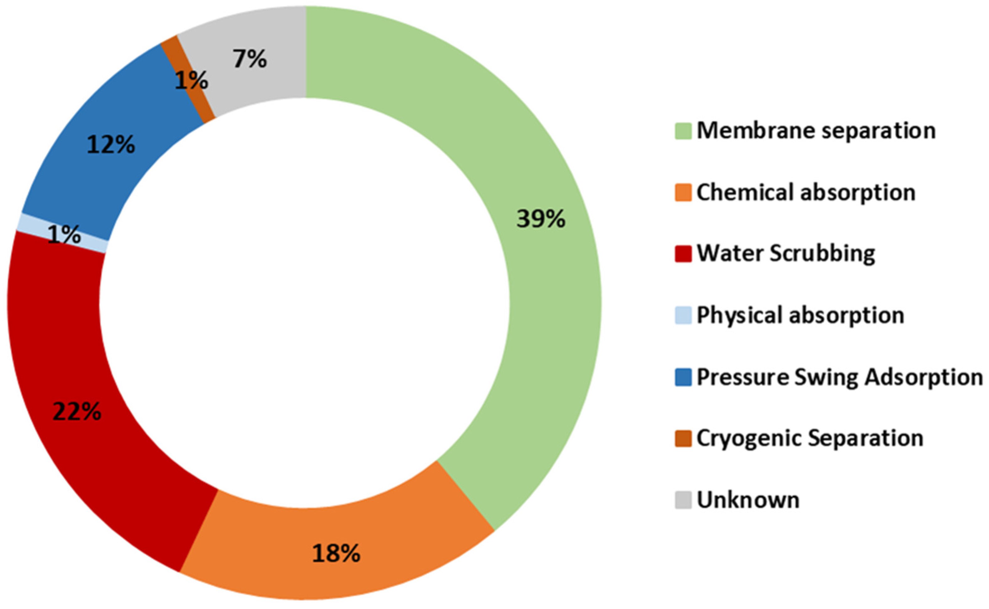
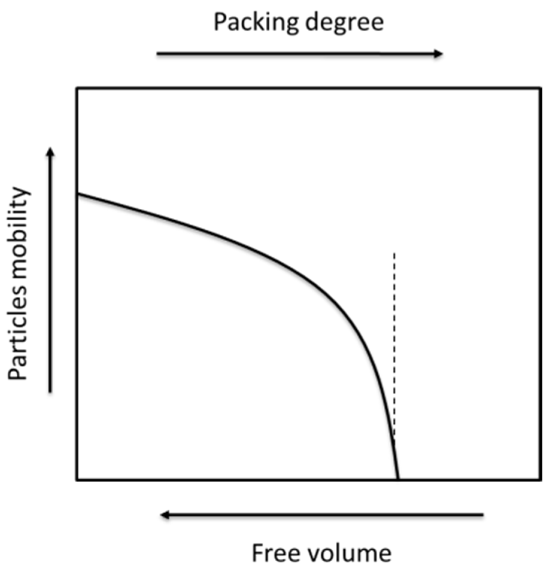
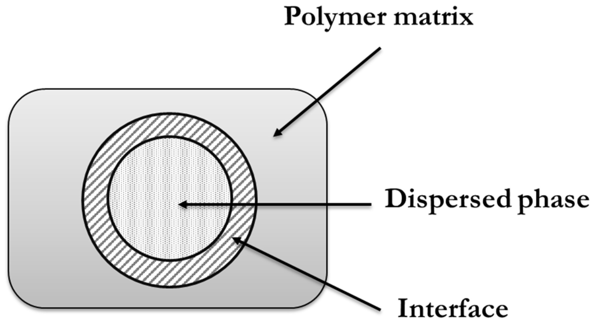
Table 1.
Tabulation of the values of upper bound slope n and the front factor k. Table adapted from Robeson, 2008.
Table 1.
Tabulation of the values of upper bound slope n and the front factor k. Table adapted from Robeson, 2008.
| Gas Pair | k (Barrer) | n |
|---|---|---|
| Before 2008 Robeson’s bond [61,65] | ||
| O2/N2 | 389,224 | −5.800 |
| CO2/CH4 | 1,073,700 | −2.6264 |
| H2/N2 | 52,918 | −1.5275 |
| H2/CH4 | 18,500 | −1.2112 |
| He/N2 | 12,500 | −1.0242 |
| He/CH4 | 5002 | −0.7857 |
| He/H2 | 960 | −4.9535 |
| CO2/N2 | NA | NA |
| N2/CH4 | NA | NA |
| H2/CO2 | 1200 | −1.9363 |
| He/CO2 | 705 | −1.220 |
| H2/O2 | 35,760 | −2.277 |
| He/O2 | 4600 | −1.295 |
| 2008 Robeson’s bond [60] | ||
| O2/N2 | 1,396,000 | −5.666 |
| CO2/CH4 | 5,369,140 | −2.636 |
| H2/N2 | 97,650 | −1.4841 |
| H2/CH4 | 27,200 | −1.107 |
| He/N2 | 19,890 | −1.017 |
| He/CH4 | 19,800 | −0.809 |
| He/H2 | 59,910 | −4.864 |
| CO2/N2 | 30,967,000 | −2.888 |
| N2/CH4 | 2570 | −4.507 |
| H2/CO2 | 4515 | −2.302 |
| He/CO2 | 3760 | −1.192 |
| H2/O2 | NA | NA |
| He/O2 | NA | NA |
Table 2.
Characteristics and typical applications of the different modules for gas separation.
| Module Configuration | Features | Typical Applications | Used by |
|---|---|---|---|
|
|
| Medal Cynara Other |
|
|
| Medal Air products Parker |
|
|
| MTR |
Publisher’s Note: MDPI stays neutral with regard to jurisdictional claims in published maps and institutional affiliations. |
© 2022 by the authors. Licensee MDPI, Basel, Switzerland. This article is an open access article distributed under the terms and conditions of the Creative Commons Attribution (CC BY) license (https://creativecommons.org/licenses/by/4.0/).
Share and Cite
MDPI and ACS Style
Soto, C.; Palacio, L.; Muñoz, R.; Prádanos, P.; Hernandez, A. Recent Advances in Membrane-Based Biogas and Biohydrogen Upgrading. Processes 2022, 10, 1918. https://doi.org/10.3390/pr10101918
AMA Style
Soto C, Palacio L, Muñoz R, Prádanos P, Hernandez A. Recent Advances in Membrane-Based Biogas and Biohydrogen Upgrading. Processes. 2022; 10(10):1918. https://doi.org/10.3390/pr10101918
Chicago/Turabian StyleSoto, Cenit, Laura Palacio, Raúl Muñoz, Pedro Prádanos, and Antonio Hernandez. 2022. "Recent Advances in Membrane-Based Biogas and Biohydrogen Upgrading" Processes 10, no. 10: 1918. https://doi.org/10.3390/pr10101918
Note that from the first issue of 2016, this journal uses article numbers instead of page numbers. See further details here.