

Integration of Decay Time Analysis and Radiation Measurement for Quantum-Dot-Based Scintillator’s Characterization


1
Department of Nuclear Engineering, Kyung-Hee University, Yongin-si 17104, Korea
2
Decommissioning Technology Research Division, Korea Atomic Energy Research Institute, Daejeon 34057, Korea
3
Laser Application Research Team, Decommissioning Technology Research Division, Korea Atomic Energy Research Institute, Daejeon 34057, Korea
4
Nuclear Science and Technology, Quantum Energy Chemical Engineering, University of Science and Technology (UST), 217 Gajeong-ro, Daejeon 34113, Korea
*
Authors to whom correspondence should be addressed.
Processes 2022, 10(10), 1920; https://doi.org/10.3390/pr10101920
Submission received: 1 July 2022
/
Revised: 19 August 2022
/
Accepted: 16 September 2022
/
Published: 22 September 2022
(This article belongs to the Special Issue Evolutionary Process for Engineering Optimization (II))
Abstract
:In this study, we demonstrated the process of an integrated apparatus for decay time analysis and gamma radiation measurement with a liquid-scintillator-based cadmium-doped zinc oxide (CZO) nanomaterial. Generally, time-resolved photon counting is an essential analysis method in the field of precision measurement in the quantum domain. Such photon counting equipment requires a pulse laser that can be repeated quickly while having a sharp pulse width of picoseconds or femtoseconds as a light source. Time-correlated single photon counting (TCSPC) equipment, which is currently a commercial product, is inconvenient for recent development research because the scintillator size and shape are limited. Here, neodymium-doped yttrium aluminum garnet (Nd/YAG) laser TCSPC equipment was constructed to analyze the fluorescence characteristics of scintillators having various sizes and shapes. Then, a liquid scintillator added with CZO nanomaterial was prepared and the Nd/YAG laser TCSPC equipment test was performed. As a result of measuring the scintillator using the manufactured Nd/YAG laser TCSPC equipment, the non-CZO liquid scintillator was analyzed at 2.30 ns and the liquid scintillator equipped with CZO-loaded nanomaterial was analyzed at 11.95 ns. It showed an error within 5% when compared with the result of commercial TCSPC equipment. In addition, it was verified that the Nd/YAG laser TCSPC system can sufficiently measure the decay time in nanoseconds (ns). Moreover, it was presented that the Compton edge energy of Cs−137 is 477.3 keV, which hardly generates a photoelectric effect, and Compton scattering mainly occurs.
1. Introduction
The radiation measurement system is vital for the actual issue in nuclear facility accident preparation, decommissioning nuclear facilities, regular environmental radiation monitoring, medical, nuclear security, and safeguards. In particular, a large-volume measurement system is required in the field of nuclear facilities’ decommissioning and environmental radiation monitoring. When dismantling a nuclear facility, radiological characterization and radiation monitoring must be performed. After decommissioning, it must be proven that the residual contamination level of the decommissioning site is below the release criteria. For this purpose, a plastic scintillator with good processability and a short decay time is widely used, but the plastic scintillator has poor resolution, so radionuclide analysis is not possible. Currently, many studies have been conducted on large-volume plastic detection systems [1,2,3,4,5,6,7].
Time-resolved photon counting is an essential analysis method in the field of precision measurement such as the classical and quantum domains. Among them, time-correlated single-photon counting (TCSPC) is a key technology for applications such as fluorescence life spectroscopy and microscope, time-open/close Raman spectroscopy, time-of-flight (ToF) 3D imaging, and computer diffusion optical tomography [8,9]. By continuously accumulating the detected signal on the time axis, an attenuation curve can be created. When the intensity of fluorescence is high, many photons are detected, and when the intensity of fluorescence is weak, fewer photons are detected. By plotting this histogram, a graph similar to the original attenuation curve can be obtained called TSCPC. Such photon-counting equipment requires a fast pulse laser with a sharp pulse width of ps (picoseconds) or fs (femtoseconds) as a light source. Micro-channel plate (MCP)-photomultiplier tubes (PMT), avalanche photodiodes (APDs), and silicon photomultipliers (SiPMs) are mainly used as detectors. PMTs are widely used because of their excellent performance of high gain, low noise, and fast timing [10,11,12]. In addition, recently, research on a portable or small detector using a single-photon avalanche diode (SPAD) has been conducted. The time resolution of SPAD is about 7 ps, and it is widely used in 3D imaging or medical fields [13,14,15,16]. If multiple photons arrive at the detector at once, the detector records only the first time it arrived. Therefore, the intensity of the light source must be adjusted so that no more than one photon is generated per pulse. In general, the amount of light is adjusted so that one photon is detected per 100 pulses [17,18,19,20,21,22]. The radiation is randomly incident when the electrical signal output is not located at the base line for receiving the next signal, which could trigger pulse pile-up. Energy information can be distorted as a result of the pile-up effect. Therefore, a high-speed pulsed laser is needed to avoid the pile-up effect.
Quantum dots such as CZO, which can control the wavelength and photo-physical properties by the size and shape of particles, have recently been widely used in the field of optical sensor development. Fluorescence analysis is used for qualitative and quantitative analysis of these materials [17,18,19,20,21,22,23,24,25]. The liquid substance used in this study is a toluene-based liquid scintillator. Organic scintillators are generally based on aromatic hydrocarbon compounds. They are also mainly used for pulse shape identification (PSD) or ultra-fast timing and counting applications. However, organic scintillators are not suitable for detecting high-energy photons such as X-rays or gamma rays. This is because the low atomic number of organic materials contributes to the reduction in the macroscopic cross-section of high-energy photons and cannot effectively generate photoelectrons. Recently, research has been conducted to develop a plastic scintillator capable of spectral detection of high-energy photons by loading high-Z nanomaterials into solvents such as polyvinyl toluene (PVT), styrene, and polyvinyl carbazole (PVK). However, a scintillator was manufactured by putting a liquid solution in a transparent cell without the polymerization procedure in this study. As the liquid scintillator does not have a polymerization process, it is possible to quickly prepare a sample according to the purpose of measurement and has the advantage of maintaining high transparency in the emission wavelength range. In 2020, the Berkeley University [26] manufactured a water-based liquid scintillator and conducted a study to measure the decay time for each concentration of PPO. The decay time was calculated as 16.9 ns when 1 wt% of PPO was added, and 15.9 ns when 2 wt% of PPO was added. A water-based liquid scintillator has a faster decay time than an inorganic scintillator, but slower than a commercial organic scintillator. Moreover, at UCLA in 2021 [27], a high-energy photon measurement study was performed by manufacturing a liquid scintillator loaded with hafnium oxide nanomaterials. As a result of testing with a liquid scintillator containing 20 wt% hafnium oxide nanomaterials and a Cs−137 source, a photopeak with 4.8% resolution at 662 keV was observed. The decay time of the liquid scintillator containing hafnium oxide nanomaterials was calculated to be 3.3 ns, which is slightly slower than that of commercial plastics (2.5 ns). However, it is much faster than a commercial inorganic scintillator.
In this study, Nd/YAG Laser TCSPC equipment was built to analyze the fluorescence characteristics of scintillators with various sizes and shapes, and an optical sensor scintillator containing cadmium-doped zinc oxide (CZO) nanomaterial was manufactured and demonstrated with Nd/YAG laser TCSPC equipment. Eventually, a process was demonstrated of an integrated apparatus for decay time analyzer and gamma radiation measurement with a liquid-scintillator-based CZO nanomaterial that could trigger a Compton edge energy.
2. Materials and Methods
2.1. Chemicals and Analysis
All reagents and chemicals were of a high purity grade. Toluene (99.9%), PPO (2,5-diphenyl−1,3-oxazole), and POPOP(1,4-bis(5-phenyl-oxazolyl−2)benzene) were purchased from Sigma-Aldrich (St. Louis, MO, USA). CZO was provided by global ZEUS (Hwaseong, Korea). Absorption/transmission and fluorescence properties were observed to evaluate the optical properties of the prepared liquid scintillator. First, absorption/transmission spectra were obtained using an optical spectrometer (FLAME UV/VIS spectrometer, Ocean Insight). This system consists of a spectrometer, a light source (DH−2000, Ocean Insight), two optical fibers, and a sample holder. The DH−2000 light source combines continuous spectra of deuterium and tungsten halogen light sources in a single optical path. The combined spectral light source produces a stable output from 215 to 2000 nm. Ten points were randomly selected and measured in the circumferential direction, and the average value was calculated. TEM analysis of CZO nanomaterial was performed using a transmission electron microscope (FE-TEM, TECNAI G2 F30 S-TWIN, FEI Company) and analyzed at low magnification (×25,000) and high magnification (×245,000).
2.2. Fabrication of a Liquid Scintillator
The liquid scintillator used in this study was placed in a 35 mL transparent cell and the timing properties were analyzed. The transparent cell size is 50 mm in diameter and 20 mm in path length. The liquid scintillator used toluene as a base matrix and was manufactured by adding fluorescent materials PPO, POPOP, and CZO nanomaterial. A CZO nanomaterial was added to improve the efficiency by increasing the reaction to photons. First, the sample was stirred for 5 hrs by adding toluene (>98%), PPO (0.4 wt%), POPOP (0.01 wt%), and CZO (0.1 wt%). The microbubbles generated through the stirring process were removed through the degassing process for 5 hrs. In addition, the liquid sample was carefully placed in a 35 mL transparent cell and sealed. Figure 1 shows the manufacturing process of a liquid scintillator. A CZO-loaded liquid scintillator and a basal liquid scintillator without CZO were fabricated. As CZO was employed at a high concentration (100 mg/mL) from the supplier, it was diluted 1/100 with toluene and used.
2.3. Set-Up of the TCSPC System and Radiation Measurement System
TCSPC system and radiation measurement system were constructed simultaneously. Figure 2 shows a schematic diagram of the manufactured TCSPC system and radiation measurement system.
A decay time analysis system to observe optical properties of scintillators was performed. The TCSPC system was constructed using Laser (3rd Harmonics of Q-switched Nd:YAG laser, Brilliant B), and the main schematic diagram of the constructed TCSPC system is shown in Figure 2 (left). This system is equipped with a band filter and a dichroic mirror to control the excitation wavelength of light. The Dichroic mirror separated Nd/YAG light into 1064 nm, 532 nm, and 355 nm. Light with a wavelength of 355 nm passed through the sample, and the signal detected by the PMT (R928, HAMAMATSU, Tokyo, Japan) was transmitted to the oscilloscope (DS6104, RIGOL, Suzhou, China) to analyze the output data from the oscilloscope. The oscilloscope stores one sample point per waveform to reduce noise. An average value of 64 collected data was used, and 10 ns pulse data were obtained. All experiments were performed in a dark box to block unnecessary light.
Not only the decay time analysis but also the radiation detection system was constructed so that the decay time and scintillation counting of the liquid sample could be measured quickly. Cs−137 point source was used, and data were analyzed based on Compton edge owing to the inherent resolution of the plastic scintillator. The radiation source was located at 20 mm from the liquid sample. The liquid scintillator was coupled with a 2-inch PMT (ET−9266KB, ET-Enterprises Ltd., Uxbridge, UK). Signals extracted from PMT were processed by Preamp (Amcrys 544, Amcrys, Kharkiv, Ukraine), Amp (DT5781, CAEN, Viareggio, Italy) and MCA (DT5781, CAEN), as shown in Figure 2 (right). Table 1 shows the components of the TCSPC system and radiation measurement.
3. Results
3.1. Characteristics of the Liquid Scintillator
Toluene was used as a polymer material, PPO as a primary fluorescent material, and POPOP as a secondary fluorescent material. When charged particles are incident on the toluene-based plastic scintillator, some energy of the particle is transferred by Coulomb interaction. The transferred energy excites the toluene molecule. The excited molecule is stabilized and emits a photon of corresponding energy. The wavelength of the emitted photons is about 300 nm ultraviolet light (UV), and emitted UV is almost reabsorbed by toluene. However, if the wavelength sifter is uniformly added to the toluene, the UV is absorbed by the wavelength shifter and converted into a relatively long wavelength by Stoke’s shift. As a result, when the charged particles are incident on the plastic, the plastic scintillator emits light in the visible range. The wavelength shifters are PPO and POPOP, which absorb light in the UV region and emit visible light at about 420 nm. Moreover, the additionally used quantum dot is cadmium-doped zinc oxide.
Figure 3 shows the results of TEM analysis of CZO nanomaterial. Figure 3a shows the result of ×25,000 magnification and Figure 3b represents the result of ×245,000 magnification. The result of magnifying a part of Figure 3a at high magnification is Figure 3b. As shown in Figure 3, CZO nanomaterial was observed to have a size of 10 nm and was dispersed without aggregation.
The advantage of quantum dots is that the emission wavelength can be controlled according to the particle size. In this experiment, it was designed to emit blue-based visible light from scintillator using a quantum dot with ~ nm size. High-Z quantum dots not only increase the energy absorption rate by increasing the reaction rate with photons, but also increase the optical gain using multiple excitons (electron-hole pairs). Figure 4 shows a liquid scintillator placed in a quartz cell after mixing all of the solvent, fluorescent dye, and nanomaterials. As shown in Figure 4, fluorescent material was mixed with the uniformly dispersed quantum dot and placed into a 50 mm diameter transparent cell and used as a liquid scintillator. Figure 4a shows a photograph of the manufactured liquid scintillator, when UV is irradiated to the liquid scintillator; it can be seen that the light is emitted evenly, which means that the added materials are dispersed without agglomeration in Figure 4b. In this study, not only the construction of the TCSPC system, but also the optical properties of the fabricated samples were analyzed. Absorbance, transmittance, and photoluminescence of the liquid scintillator were performed.
Absorbance and transmittance were measured three times by randomly selecting ten points of a 50 mm diameter samples and then averaged. When light passes through, the intensity of the light decreases because the light is absorbed by the sample. The amount of light that has passed through the sample (Transmittance, T) is expressed as the ratio of the intensity of light (I0) when there is no light-absorbing material and the intensity (I) of light when there is a light-absorbing material. It is called transmittance and is expressed as T = I/I0. As shown in Figure 5a, the absorption rate of the CZO-loaded liquid scintillator is larger at a wavelength above 400 nm. As shown in Figure 5b, a CZO-loaded liquid scintillator (toluene + PPO + POPOP + CZO) transmits over 400 nm like the basal liquid scintillator (toluene + PPO + POPOP), and transmittance was lower than that of the basal liquid scintillator owing to the effect of the quantum dot. Self-quenching occurred as a result of the quantum dot, which is a high atomic number material, and the quantum effect tends to decrease. Photoluminescence was measured using a spectrophotofluorometer and analyzed at excitation wavelengths of 264 nm and 316 nm, respectively. As shown in Figure 6a,b, it shows an emission wavelength at about 420 nm. Figure 6c,d with quantum dots such as CZO show an emission wavelength at about 450 nm. Figure 6a,b show weak peaks around 440 nm, which appears to be the effect of the secondary nanomaterial (POPOP), and the effect was not observed in Figure 6c,d. All of the energy emitted from POPOP is absorbed by CZO.
3.2. TCSPC Analysis and Radiation Measurement
The TCSPC system and radiation measurement system were directly constructed for the fast analysis of samples of various sizes, shapes, and types. The customized TCSPC system and radiation measurement system are shown in Figure 7. Figure 7a shows a TCSPC system and Figure 7b shows a radiation measurement system. In Figure 7a, all of the components used are marked, and the sample part blocks unnecessary light using a dark box. An Nd/YAG laser was used as the light source of the customized TCSPC system. The laser light divided by the dichroic mirror excites the sample, and the photon emitted from the excited sample is detected by the PMT and converted into an electrical pulse. Then, electrical pulses were analyzed through an oscilloscope. In Figure 7b, the radiation measurement system is located next to the TCSPC system and is configured so that it can be measured immediately from an integrated apparatus.
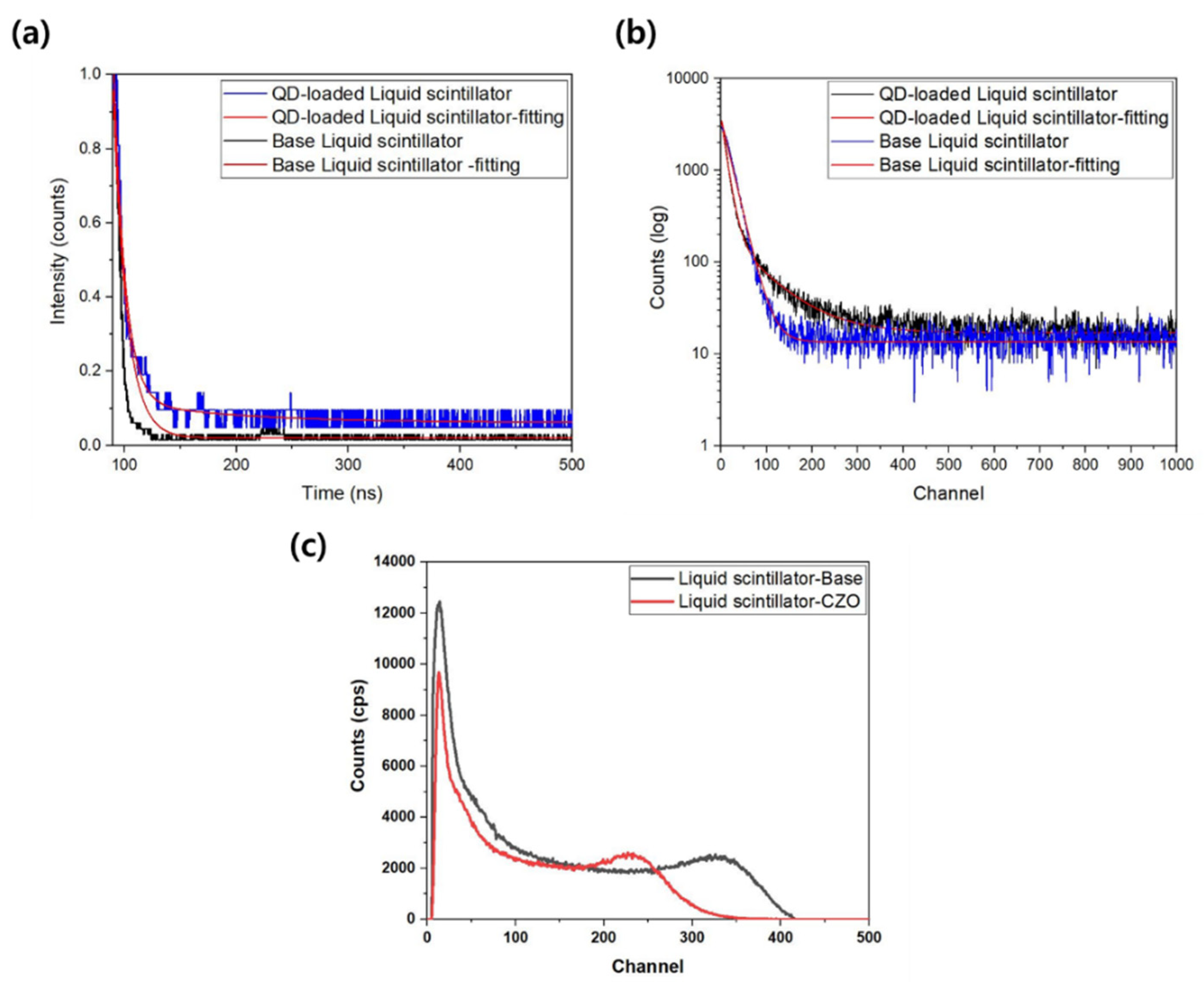
The customized TCSPC system was examined using two liquid scintillators prepared in this study. As shown in Figure 8a,b, decay time was calculated through Equation (1) based on the raw data of the fluorescence decay curve. Equation (1) is used for multi-exponential fitting of the spectrum.
I = A1∗exp(−t1/τ1) + A2∗exp(−t2/τ2)
Here, An is the amplitude of nth component and τn is the decay time of nth component.
Table 2 shows the decay times for two liquid scintillators. The basal liquid scintillator was analyzed at 2.30 ns and the CZO-loaded liquid scintillator was analyzed at 11.95 ns. This is because delayed fluorescence occurred as a result of CZO of the high-Z material. In addition, to evaluate the reliability of the results, analysis was performed using commercial equipment (Spectrophotofluorometer with TCSPC, Fluorolog3, HORIBA). As a result, the basal liquid scintillator was analyzed at 2.18 ns, and the CZO-loaded liquid scintillator was analyzed at 12.03 ns. For the basal liquid scintillator, single-exponential fitting was performed because the error was large when multi-exponential fitting was performed. As multiple excitons can be emitted simultaneously, a single exponential fit is not always correct. If the excited emitter is relaxed through many channels to the ground state, it may be necessary to perform two or more exponential fittings rather than a single exponential fitting. For the CZO-loaded liquid scintillator, the error was the lowest when double exponential fitting was performed. When comparing the results with the commercial equipment using the same fitting methods, it was analyzed that the difference with commercial equipment was within 5%, and the reliability of the customized TCSPC system was verified.
Incident photons interact with the CZO through the photoelectric effect and tend to deposit all of their energy into the photoelectrons produced. This energy excites the plastic matrix and the dye, going through an energy cascade process. Because of these energy transfer characteristics, energy transfer to the fluorescent dye was maximized, and quantum efficiency was improved. To evaluate the performance of the liquid scintillator manufactured by adding CZO nanomaterial, a measurement test was performed by placing a source at a distance of 20 mm from the scintillator surface. The signal generated by the detection system is amplified through the preamplifier and amplifier. The amplified analog signal is digitized and stored through the MCA. A high voltage was applied to the detection system so that the generated electrons were collected on the electrode. The system consisted of PMT, power supply, preamp, amp, and MCA. Unlike inorganic scintillators, a liquid scintillator hardly generates a photoelectric effect and mainly Compton scattering occurs. The Compton edge energy of Cs−137 is 477.3 keV. As the liquid scintillator is dominated by Compton scattering, energy calibration was performed using the Compton edge, and a measurement test was performed for 10 min. The measurement test result using Cs−137 source is shown in Figure 8c. It was analyzed that the spectrum of the liquid scintillator containing the CZO nanomaterial was shifted to lower energy than the spectrum of the liquid scintillator without the CZO nanomaterial. This is considered to be because fluorescence quenching occurred because of CZO nanomaterial, with a high atomic number.
Table 3 shows the results of investigation and analysis by other references of the evaluation of decay time and radiation measurement. Bulk materials such as BGO, CsI (Tl), and NaI (Tl) have decay times of several hundred nanoseconds. A typical plastic scintillator has a decay time of about 2 ns, but nanomaterials with a high atomic number have a decay time of several nanoseconds to several tens of nanoseconds. The decay time of the CZO-loaded liquid scintillator shows a similar trend to the analysis of other references. An organic scintillator without high atomic number material shows fast decay time performance, but when high atomic number nanomaterial is added, the decay time becomes slow. The reason is that the number of transitions to the triplet state generating delayed fluorescence increases because of the nanomaterials. There are many research cases that analyze photopeak for gamma sources using nanomaterials. As the application fields of optical sensors are diverse, scintillators of various shapes, sizes, and types are manufactured. Therefore, a customized TCSPC system that can directly measure various samples without additional processes was constructed. When analyzing the decay time in nanoseconds, it was verified that it is sufficiently possible with a customized TCSPC system.
4. Conclusions
In this study, we demonstrated the process of an integrated apparatus for decay time analysis and gamma radiation measurement with a liquid scintillator based on cadmium-doped zinc oxide (CZO) nanomaterial. Time resolution can be obtained in various methods depending on the required sensitivity and time domain. Time domain methods are more diverse than frequency domain methods for measuring the lifetime of fluorescence. A representative method is time-correlated single photon counting. It measures the time the photons arrive after excitation, which means to obtain a decay curve by accumulating the data on the time axis. A customized TCSPC system capable of analyzing the decay time of various samples was constructed. This system used an Nd/YAG laser, dichroic mirror, and band filter to irradiate the sample with appropriate light. Then, the signal was analyzed using a PMT and an oscilloscope. Unlike commercial TCSPC equipment, a customized TCSPC system can analyze samples of various sizes, shapes, and types. In addition, to evaluate the reliability of this system, base and quantum dot-loaded liquid scintillators were manufactured and the decay time was measured. When comparing the results with commercial TCSPC equipment, it was confirmed that the error was within 5%. Therefore, the applicability of the customized TCSPC system was demonstrated for the purpose of analyzing the timing performance in nanoseconds. In the future, if the PMT of this system is configured as fast PMT, it is expected that the timing performance in picoseconds also makes it possible to analyze various types of scintillators.
As a result of performing a measurement experiment using the Cs−137 source, it was analyzed that the liquid scintillator containing CZO was shifted to a lower energy than the liquid scintillator without the CZO representing the Compton edge energy of Cs−137 is 477.3 keV, which hardly generates a photoelectric effect, and mainly Compton scattering occurs. Finally, a system for radiation measurement and decay time analysis was directly constructed using a manufactured liquid scintillator based on toluene, fluorescent dyes, and nanomaterial. Moreover, this process on a system can directly configure and measure the properties of liquid scintillators of various sizes and different shapes from an apparatus for decay time analysis and radiation measurements.
Author Contributions
Conceptualization and original draft preparation, S.M.; experimental setup, S.M. and K.-H.K.; supervision and editing, B.S., C.R. and S.H. All authors have read and agreed to the published version of the manuscript.
Funding
This work was supported by [the National Research Foundation of Korea (NRF)] Grant funded by [the Ministry of Science and ICT] [NRF−2020M2C9A1068162]. This work was supported by [the National Research Foundation of Korea (NRF)] Grant funded by [the Ministry of Science and ICT] [RS−2022–00154985].
Data Availability Statement
Not applicable.
Acknowledgments
Special thanks to global ZEUS Team members from Korea for their help and support of CZO nanomaterial used in this experiment.
Conflicts of Interest
The authors declare no conflict of interest.
References
- Min, S.J.; Kang, H.R.; Seo, B.K.; Cheong, J.H.; Roh, C.H.; Hong, S.B. Wireless backpack system for detection of radioactive cesium on contaminated soil using portable plasitc scintillator with efficient readout device. Electronics 2021, 10, 2833. [Google Scholar] [CrossRef]
- Min, S.J.; Ko, K.H.; Seo, B.K.; Cheong, J.H.; Roh, C.H.; Hong, S.B. Integrated and portable based on functional plastic scintillator for detection of radioactive cesium. Appl. Sci. 2021, 11, 5210. [Google Scholar] [CrossRef]
- Kim, H.J.; Hyun, Y.J.; Kim, Y.J.; Hwang, S.I. A study on effective management scheme for soil and groundwater contamination by radioactive materials due to nuclear accidents. J. Soil Groundw. Environ. 2011, 16, 113–121. [Google Scholar] [CrossRef]
- Lee, K.J. Development of a Vehicle-Mounted Large Area Radioactive Contamination Measurement Equipment. Master’s Thesis, Josun University, Gwangju, Korea, February 2020. [Google Scholar]
- Lee, B.C.; Hong, S.B.; Seo, B.K.; Kim, J.H.; Kim, Y.E. Gamma-ray spectrometry to find the distribution of diffused radioactive sources underground. New Phys. Sae Mulli 2019, 69, 882. [Google Scholar] [CrossRef]
- Ji, Y.Y.; Min, B.I.; Seo, K.S.; Jeong, S.Y.; Kim, K.P.; Park, J.H. Technical status of environmental radiation monitoring using a UAV and its field application to the aerial survey. J. Korea Ind. Inf. Syst. Res. 2020, 25, 31–39. [Google Scholar] [CrossRef]
- Min, S.J.; Seo, B.K.; Roh, C.H.; Hong, S.B.; Cheong, J.H. Phoswich detectors in sensing applications. Sensors 2021, 21, 4047. [Google Scholar] [CrossRef] [PubMed]
- Gweon, D.G. Design and Analysis of Spectral Fluorescence Lifetime Imaging Microscopy Using Tunable Bandpass Filter. Master’s Thesis, Korea Advanced Institute of Science and Technology (KAIST), Daejeon, Korea, February 2012. [Google Scholar]
- Gratton, E.; Breusegem, S.; Sutin, J.; Ruan, Q.; Barry, N. Fluorescence lifetime imaging for the two-photon microscope: Time domain and frequency domain methods. J. Biomed. Opt. 2003, 8, 381–390. [Google Scholar] [CrossRef]
- Jiang, W.; Chalich, Y.; Deen, M.J. Sensors for positron emission tomography application. Sensors 2019, 19, 5019. [Google Scholar] [CrossRef] [PubMed]
- Jiang, W.; Scott, R.; Deen, M.J. Differential quench and reset circuit for single-photon avalanche diodes. J. Lightwave Technol. 2021, 39, 7334–7342. [Google Scholar] [CrossRef]
- Jiang, W.; Chalich, Y.; Scott, R.; Deen, M.J. Time-gated and Multi-Junction SPADs in Standard 65 nm CMOS Technology. IEEE Sens. J. 2021, 21, 12092–12103. [Google Scholar] [CrossRef]
- Alayed, M.; Palubiak, D.P.; Deen, M.J. Characterization of a time-resolved diffuse optical spectroscopy prototype using low-cost, compact single photon avalanche detectors for tissue optics application. Sensors 2018, 18, 3680. [Google Scholar] [CrossRef]
- Alayed, M.; Naser, M.A.; Aden-Ali, I.; Deen, M.J. Time-resolved diffuse optical tomography system using an accelerated inverse problem solver. Opt. Express 2018, 26, 963–979. [Google Scholar] [CrossRef]
- Li, Z.; Deen, M.J.; Kumar, S.; Selvaganapathy, P.R. Raman Spectroscopy for In-Line Water Quality Monitoring-Instrumentation and Potential. Sensors 2014, 14, 17275–17303. [Google Scholar] [CrossRef]
- Li, Z.; Deen, M.J. Towards a Portable Raman Spectrometer Using a Concave Grating and a Time-gated CMOS SPAD. Opt. Express 2014, 22, 18736–18747. [Google Scholar] [CrossRef]
- Pellegrini, S.; Buller, G.S.; Smith, J.M.; Wallace, A.M. Laser-based distance measurement using picosecond resolution time-correlated single-photon counting. Meas. Sci. Technol. 2000, 11, 712–716. [Google Scholar] [CrossRef]
- Li, B.; Bartos, J.; Xie, Y.; Huang, S.W. Time-magnified photon counting with 550-fs resolution. Optica 2021, 8, 1109–1112. [Google Scholar] [CrossRef]
- Becker, W.; Bergmann, A.; Briskup, C. Multispectral Fluorescence Lifetime Imaging by TCSPC. Microsc. Res. Tech. 2007, 70, 403–409. [Google Scholar] [CrossRef]
- Datta, R.; Gillette, A.; Stefely, M.; Skala, M.C. Recent innovations in fluorescence lifetime imaging microscopy for biology and medicine. J. Biomed. Opt. 2021, 26, 070603. [Google Scholar] [CrossRef]
- Farina, S.; Acconcia, G.; Labanca, I.; Ghioni, M.; Rech, I. Toward ultra-fast time-correlated single-photon counting: A compact module to surpass the pile-up limit. Rev. Sci. Instrum. 2021, 92, 063702. [Google Scholar] [CrossRef]
- Becker, W.; Hickl, H.; Zander, C.; Drexhage, K.H.; Sauer, M.; Siebert, S.; Wolfrum, J. Time-resolved detection and identification of single analyte molecules in microcapillaries by time-correlated single-photon counting (TCSPC). Rev. Sci. Instrum. 1999, 70, 1835. [Google Scholar] [CrossRef]
- Samimi, K.; Guzman, E.C.; Trier, S.M.; Pham, D.L.; Qian, T.; Skala, M.C. Time-domain single photon-excited autofluorescence lifetime for label-free detection of T cell activation. Opt. Lett. 2021, 46, 2168–2171. [Google Scholar] [CrossRef]
- Liu, X.; Ma, Y.; Li, S.; Yang, J.; Zhang, Z.; Tian, X. Photon counting correction method to improve the quality of reconstructed images in single photon compressive imaging systems. Opt. Express 2021, 29, 37945–37961. [Google Scholar] [CrossRef]
- Man, M.T.; Lee, H.S. Clarifying photoluminescence decay dynamics of self-assembled quantum dots. Sci. Rep. 2019, 9, 4613. [Google Scholar] [CrossRef]
- Onken, D.R.; Moretti, F.; Caravaca, J.; Yeh, M.; Gann, G.D.O.; Bourret, E.D. Time response of water-based liquid scintillator from X-ray excitation. Mater. Adv. 2020, 1, 71–76. [Google Scholar] [CrossRef]
- Zhao, H.; Yu, H.; Redding, C.; Li, Z.; Chen, T.; Meng, Y.; Hajagos, T.J.; Hayward, J.P.; Pei, Q. Scintillation Liquids loaded with Hafnium Oxide Nanoparticles for spectral resolution of gamma rays. Appl. Nano Mater. 2021, 4, 1220–1227. [Google Scholar] [CrossRef]
- Cresswell, A.; Sanderson, D.; Murpgy, S. Improved NaI(Tl) and CsI(Tl)Detector Arrays for Environmental Airborne Gamma Spectrometry: Technical Progress Report; Technical Report; Scottish Universities Research and Reactor Centre: East Kilbride, UK, 1999. [Google Scholar]
- Gundacker, S.; Turtos, R.M.; Auffray, E.; Lecoq, P. Precise rise and decay time measurements of inorganic scintillators by means of X-ray and 511keV excitation. Nucl. Instrum. Methods Phys. Res. Sect. A 2018, 891, 42–52. [Google Scholar] [CrossRef]
- Park, J.M.; Kim, H.J.; Hwang, Y.S.; Kim, D.H.; Park, H.W. Scintillation properties of quantum dot styrene based plastic scintillators. J. Lumin. 2014, 146, 157–161. [Google Scholar] [CrossRef]
- Sato, A.; Magi, A.; Koshimizu, M.; Fujimoto, Y.; Kishimoto, S.; Asai, K. Photoluminescence and scintillation characteristics of Bi-loaded PVK-based plastic scintillators for the high counting rate measurement of high energy X-rays. RCS Adv. 2021, 11, 15581–15589. [Google Scholar] [CrossRef]
- Ahirwar, S.; Mallick, S.; Bahadur, D. Electrochemical method to prepare graphene quantum dots and graphene oxide quantum dots. ACS Omega 2017, 2, 8343–8353. [Google Scholar] [CrossRef]
- Franizza, E.; Urso, C.; Iacobazzi, R.M.; Depalo, N.; Corricelli, M.; Panniello, A.; Agostiano, A.; Denora, N.; Laquintana, V.; Striccoli, M.; et al. Fabrication of photoactive heterostructures based on quantum dots decorated with Au nanoparticles. Sci. Technol. Adv. Mater. 2016, 17, 98–108. [Google Scholar] [CrossRef] [Green Version]
- Yuan, C.T.; Chou, W.C.; Tang, J.; Lin, C.A.; Chang, W.H.; Shen, J.L.; Chuu, D.S. Single fluorescent gold nanoclusters. Optics Express 2009, 17, 16111–16118. [Google Scholar] [CrossRef]
- Uddin, J.; Ghann, W. Terahertz spectroscopic studies of quantum dots–conjugated gold nanoparticles. Mater. Sci. Eng. 2018, 2, 75–81. [Google Scholar] [CrossRef]
- Rajakrishna, K.; Dhanasekaran, A.; Yuvaraj, N.; Ajoy, K.C.; Venkatraman, B. Effect of high Z materials loading in the performance of polystyrene-based thin-film plastic scintillators. Nucl. Instrum. Methods Phys. Res. Sect. A 2021, 1008, 165454. [Google Scholar] [CrossRef]
- Rajakrishna, K.; Dhanasekaran, A.; Yuvaraj, N.; Ajoy, K.C.; Venkatraman, B.; Jose, M.T. Improvement in plastic scintillator with loading of BaFBr:Eu2+ Radioluminescence phosphor. IEEE Trans. Nucl. Sci. 2021, 68, 1286–1295. [Google Scholar] [CrossRef]
- Villemot, V.; Dufour, N.; Mauree, S.; Sabot, B.; Bertrand, G.H.V.; Hamel, M. From sintering to particle discrimination: New opportunities in Metal-organic frameworks scintillators. Adv. Photonics Res. 2021, 3, 2100259. [Google Scholar] [CrossRef]
- Cherepy, N.J.; Scanner, R.D.; Beck, P.R.; Swanberg, E.L.; Tillotson, T.M.; Payne, S.A.; Hurlbut, C.R. Bismuth- and lithium-loaded plastic scintillators for gamma and neutron detection. Nucl. Instrum. Methods Phys. Res. Sect. A 2015, 778, 126–132. [Google Scholar] [CrossRef]
- Liu, C.; Li, Z.; Hajagos, T.J.; Kishpaugh, D.; Chen, D.Y.; Pei, Q. Transparent Ultra-High-Loading quantum dot/polymer nanocomposite monolith for gamma scintillation. ACS Nano 2017, 11, 6422–6430. [Google Scholar] [CrossRef]
- Egner, B.V.; Febbraro, M.; Bevins, J.E. Characterization of a boron-loaded deuterated liquid scintillator for fast and thermal neutron detection. Nucl. Instrum. Methods Phys. Res. Sect. A 2021, 996, 165153. [Google Scholar] [CrossRef]
- Xu, Q.; Juang, J.; Liu, J.; Wang, J.; Zhou, S.; Wang, X.; Nie, J.; Guo, Y.; Ouyang, X. Lead halide perovskite quantum dots based liquid scintillator for x-ray detection. Nanotechnology 2021, 32, 205201. [Google Scholar] [CrossRef]
Figure 1.
A schematic procedure for the manufacture of a liquid scintillator.
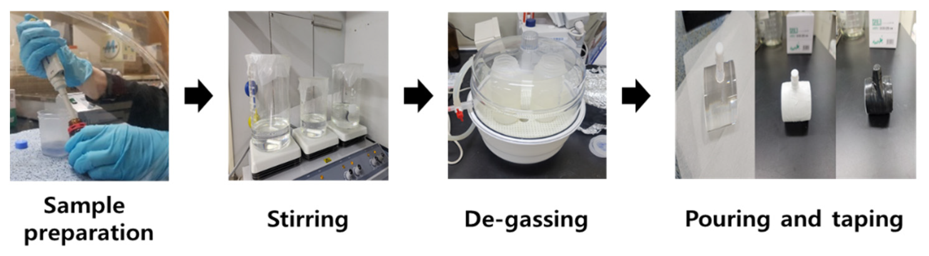
Figure 2.
A schematic diagram for decay time analysis of TCSPC and the radiation measurement system.
Figure 2.
A schematic diagram for decay time analysis of TCSPC and the radiation measurement system.
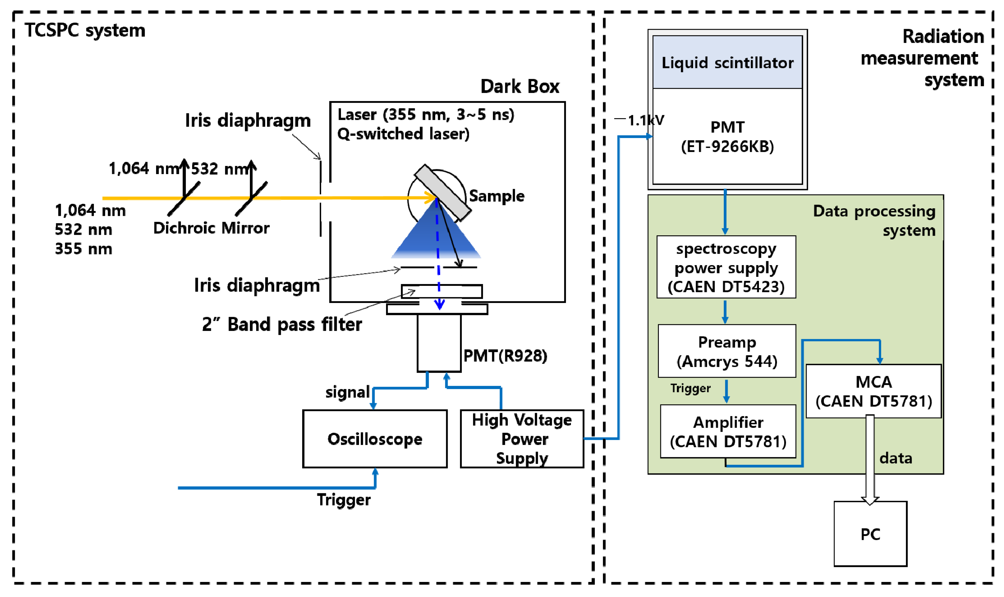
Figure 3.
TEM images of the CZO nanomaterial: (a) ×25,000; (b) ×245,000.

Figure 4.
A real photo of a liquid scintillator (a) and photo of scintillation under UV 365 nm irradiation (b).
Figure 4.
A real photo of a liquid scintillator (a) and photo of scintillation under UV 365 nm irradiation (b).

Figure 5.
Absorbance (a) and transmittance (b) of the liquid scintillator.
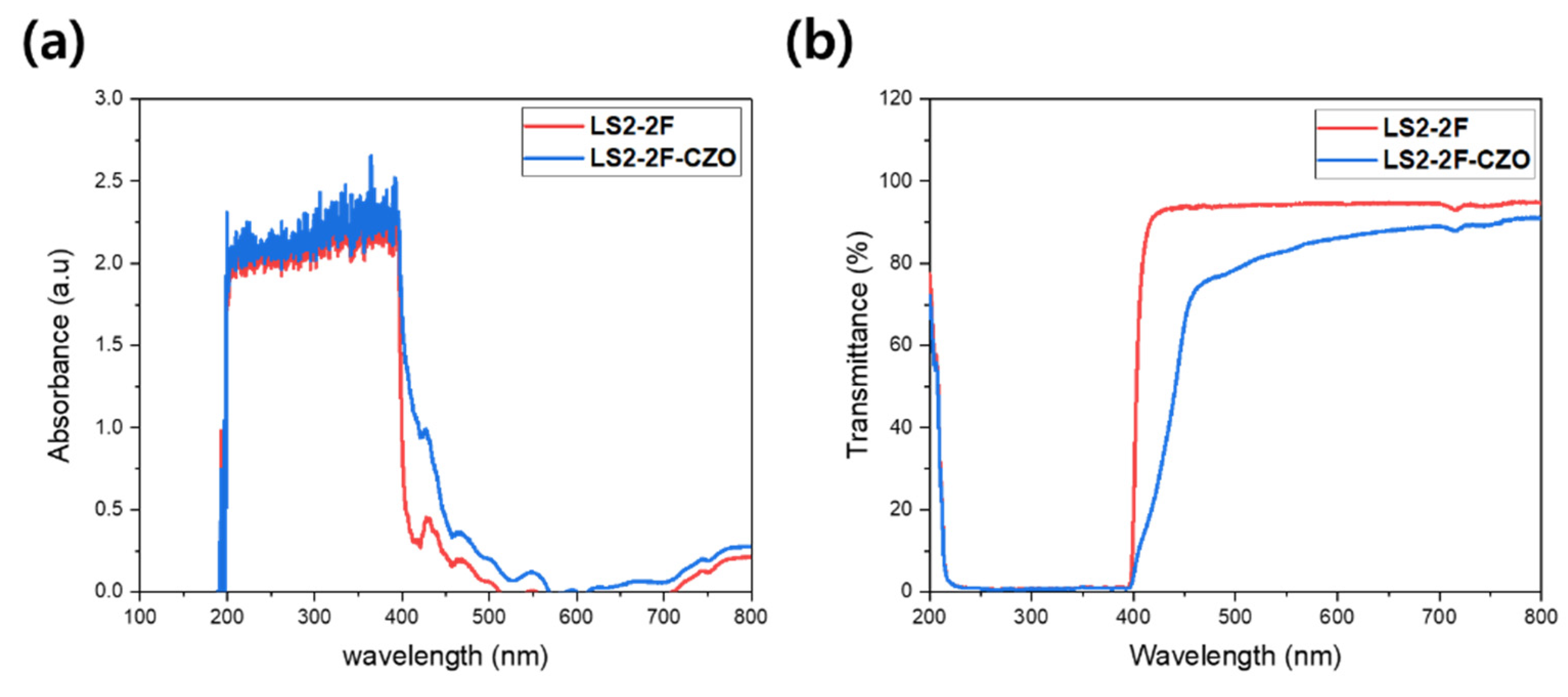
Figure 6.
Photoluminescence of the liquid scintillator (a) PL results of the base liquid scintillator under 264 nm excitation; (b) PL results of the base liquid scintillator under 316 nm excitation; (c) PL results of the CZO-loaded liquid scintillator under 264 nm excitation; (d) PL results of the CZO-loaded liquid scintillator under 316 nm excitation.
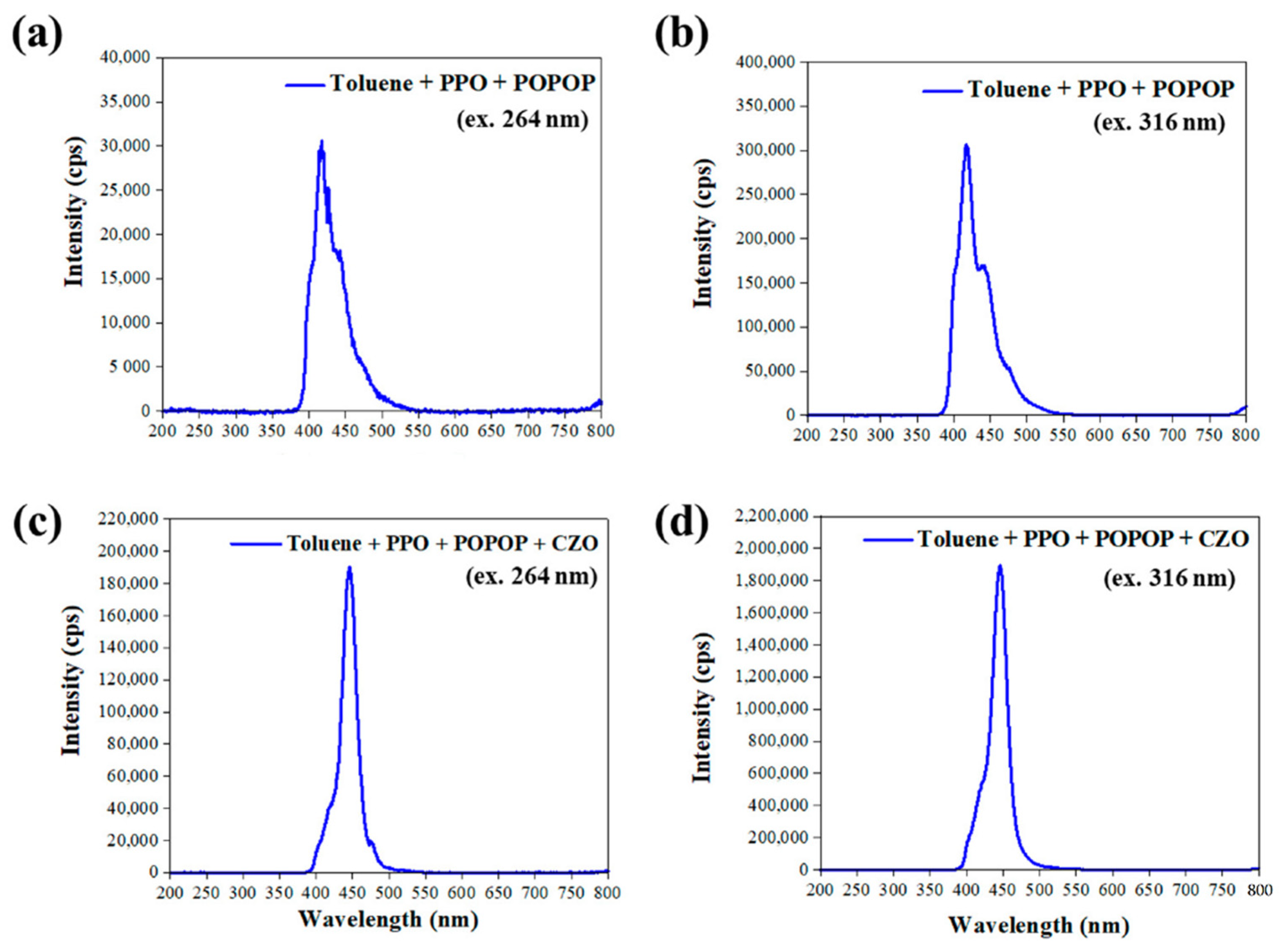
Figure 7.
Setup of the decay time analysis system using the Nd/YAG laser (a) and radiation measurement system (b).
Figure 7.
Setup of the decay time analysis system using the Nd/YAG laser (a) and radiation measurement system (b).
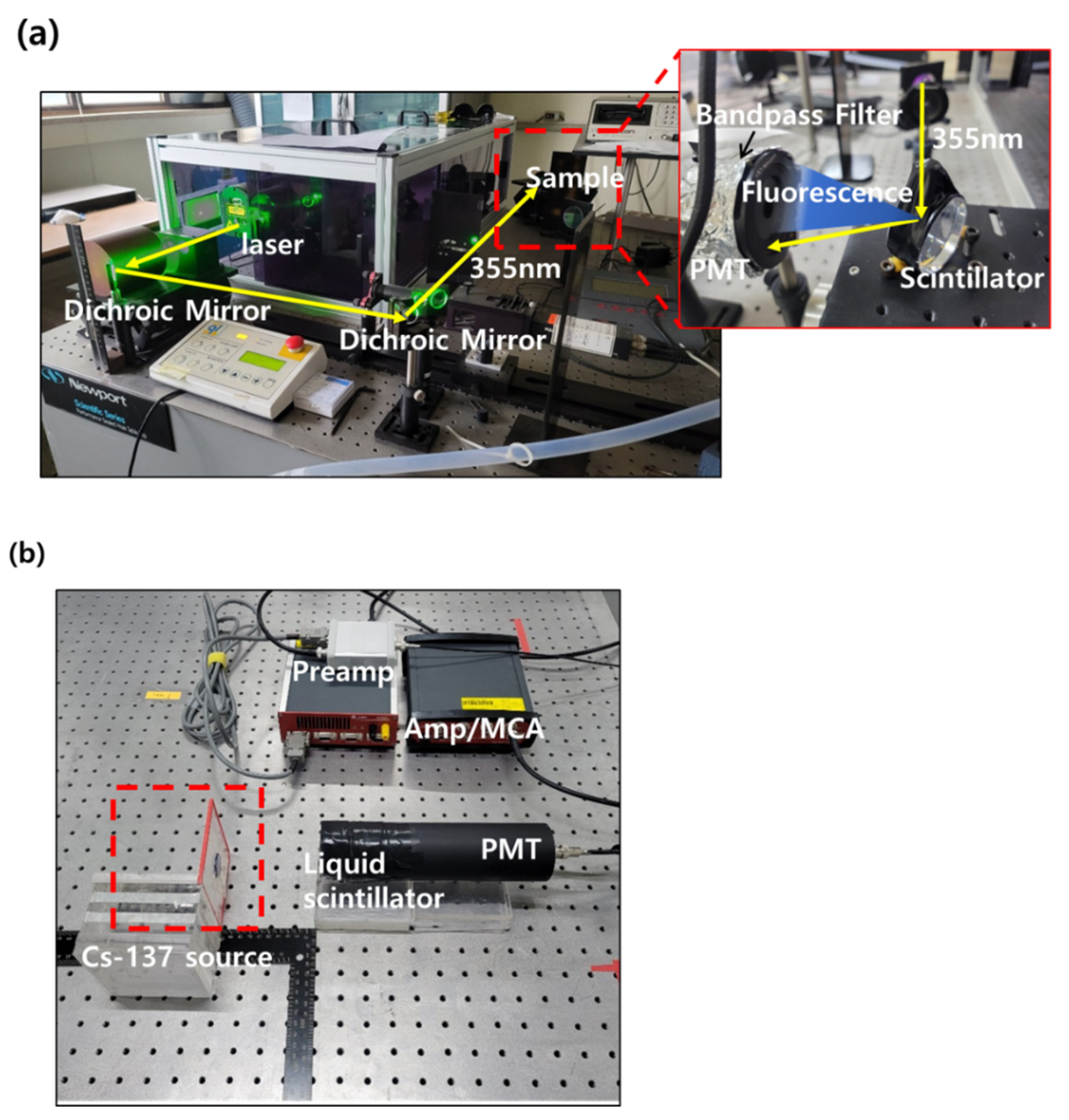
Figure 8.
Decay time spectra and radiation measurement spectra of liquid scintillators: (a) decay time analysis system using the Nd/YAG laser TCSPC; (b) decay time analysis system using the pulsed laser diode TCSPC; (c) radiological measurement to Cs−137 source.
Figure 8.
Decay time spectra and radiation measurement spectra of liquid scintillators: (a) decay time analysis system using the Nd/YAG laser TCSPC; (b) decay time analysis system using the pulsed laser diode TCSPC; (c) radiological measurement to Cs−137 source.

Table 1.
Components for the TCSPC system and radiation measurement system.
| Component | Model No. | Company |
|---|---|---|
| Laser | Brilliant B | Quantel |
| Dichroic Mirror −532 nm | - | KEOC |
| Dichroic Mirror −355 nm | - | KEOC |
| Iris diaphragm | - | THORLABS |
| Band pass filter | FL355–10 | THORLABS |
| PMT (for TCSPC) | R928 | Hamamatsu Photonics |
| High Voltage Power Supply | PS325/2500 V−25 W | Stanford Research Systems |
| Oscilloscope | DS6104 | RIGOL |
| PMT (for radiation measurement) | ET−9266KB | ET-Enterprises Ltd. |
| Preamplifier | Amcrys 544 | Amcrys |
| Amplifier | CAEN DT5781 | CAEN |
| MCA | CAEN DT5781 | CAEN |
Table 2.
Decay time constants of the CZO-loaded liquid scintillator.
| τ1 (ns) | τ2 (ns) | τavg (ns) | χ2 | |
|---|---|---|---|---|
| Base | 2.18 | - | 2.18 | 1.66 |
| CZO-loaded liquid scintillator | 11.47 | 12.43 | 11.95 | 1.17 |
Table 3.
Methods of decay time analysis and radiation measurement used in other references.
| No. | Materials | Decay Time (ns) | Method | Refs. | |
|---|---|---|---|---|---|
| Decay Time Analysis | Radiation Measurement | ||||
| 1 | BGO (Bi4Ge3O12) | 300 | Decay time is not analyzed | -This is a research case comparing the performance of NaI (Tl) and CsI (Tl), and its intended resolution and efficiency by adjusting HV, timing, and gain, among others. -Photopeak analysis was performed using Cs-137, Co-60, and Ba-133 sources. | [28] |
| 2 | CsI (Tl) | 900 | |||
| 3 | NaI (Tl) | 230 | |||
| 4 | Typical Plastic | 2~2.5 | |||
| 5 | GAGG:Ce | 203 | Using X-ray and 511 keV excitation | No detection properties were performed | [29] |
| 6 | GAGG:Ce:Mg | 124 | |||
| 7 | LuAG:Ce | 940.5 | |||
| 8 | LuAG:Ce:Mg | 358 | |||
| 9 | YAG:Ce | 271 | |||
| 10 | YAG:Ce:Mg | 92.5 | |||
| 11 | LuAG:Pr | 473 | |||
| 12 | Plastic (Styrene + PPO + CdSe/ZnS) | 6.9 | Using Cs-137 (661 keV) gamma ray source | No detection properties were performed | [30] |
| 13 | Plasitc (PVK + bis-MSB + 0 wt% BiPh3) | 6.9 | Using a flashlamp-pumped 266 nm Nd/YAG laser | Observe the pulse height spectra of a scintillation detector equipped with a PVK-based plastic scintillator with different bis-MSB contents at 67.41 keV X-ray | [31] |
| 14 | Plasitc (PVK + bis-MSB + 5 wt% BiPh3) | 5.3 | |||
| 15 | Plasitc (PVK + bis-MSB + 10 wt% BiPh3) | 5.1 | |||
| 16 | Plasitc (PVK + bis-MSB + 15 wt% BiPh3) | 4.2 | |||
| 17 | Graphene quantum dot | 2~6 | Using pulsed laser diode (excited at 375 nm) | No detection properties were performed | [32] |
| 18 | CdSe/ZnS | 14 | Using picosecond laser diode 375 nm (NanoLED 375 L) | No detection properties were performed | [33] |
| 19 | Au nanocrystal | 7 | Using pulsed laser diode (excited at ~460 nm) | No detection properties were performed | [34] |
| 20 | CdSe/Zn QD | 9.33 | Using pulsed nano LED (Delta LED) 340 nm | No detection properties were performed | [35] |
| 21 | CdSe/Zn-Au nanoparticle | 4.68 | |||
| 22 | Plastic (polystyrene + [BaFBr:Eu2+ or BaF2 or Gd2O3 or Gd2OS or CeO2 or Bi2O3]) | - | Decay time is not analyzed | This study evaluated the performance of alpha, beta, neutron, and gamma (Pu-238, C-14, Sr-90, Am-241, Ba-133, Cs-137, Am-Be) measurement by loading materials with high atomic numbers on plastic-based materials | [36] |
| 23 | Plastic (polystyrene + p-xylene + PPO + POPOP + BaFBr:Eu2+) | ~10 ns | F920 flash lamp (Excited at 290 nm) | This study evaluated the detection performance for alpha, beta, neutron, and gamma (Pu-238, C-14, Cl-36, Sr-90, Am-241, Cs-137, Am-Be) by BaFBr:Eu2+ contents | [37] |
| 24 | MOF-205 (Metal-organic frameworks scintillators) | 14.3 | Using pulsed laser diode (excited at 274 nm) and X-ray excitation | This study evaluated the detection properties for Cm-244, Co-60, Cl-36, Sr-90, and Am-241 sources | [38] |
| 25 | Plastic (PVT + PPO + DPA + TPB + Bismuth carboxylates) | - | Decay time is not analyzed | Gamma and neutron detection characteristics and PSD test were performed using Cs-137 and Cf-252 source | [39] |
| 26 | Plastic (PVT + PPO + DPA + TPB + Lithium carboxylates) | ||||
| 27 | Plastic (PVT + FBtF + BMEP + CZS (CdZnS)) | 7 (For 2% FBtF/PVT sample) | Using 10uCi Cs-137 (661 keV) gamma ray source | This is a case study in which detection characteristics were evaluated for Cs-137 gamma nuclide and photopeak was observed | [40] |
| 28 | Toluene + PPO + POPOP + Boron (Liquid scintillator) | - | Decay time is not analyzed | Gamma and neutron detection characteristics and PSD test were performed using Cs-137, Am-Be, and Pu-Be sources. | [41] |
| 29 | Perovskite (MAPbBr3) (liquid scintillator) | 58.8 | Using picosecond pulsed diode 365 nm | This study evaluated steady-state photoluminescence (PL) and X-ray excited PL spectra by excitation with 365 nm laser and X-ray (X-ray tube with Ag target, operating voltage 45 kV, current 0.2 mA), respectively | [42] |
| 30 | Perovskite (CsPbBr3) (liquid scintillator) | 44.2 | |||
| 31 | Toluene + Napthalene + PBD + POPOP + HfO2 (liquid scintillator) | 3.3 | Using Cs-137 (661 keV) gamma ray source | This is a case study in which detection characteristics were evaluated for Cs-137 gamma nuclide and photopeak was observed using a liquid scintillator | [27] |
| 32 | Toluene + PPO + POPOP + CZO (liquid scintillator) | 11.95 | Nd/YAG laser | In this study, Cs-137 gamma detection characteristics were evaluated using a liquid scintillator | This work |
Publisher’s Note: MDPI stays neutral with regard to jurisdictional claims in published maps and institutional affiliations. |
© 2022 by the authors. Licensee MDPI, Basel, Switzerland. This article is an open access article distributed under the terms and conditions of the Creative Commons Attribution (CC BY) license (https://creativecommons.org/licenses/by/4.0/).
Share and Cite
MDPI and ACS Style
Min, S.; Ko, K.-H.; Seo, B.; Roh, C.; Hong, S. Integration of Decay Time Analysis and Radiation Measurement for Quantum-Dot-Based Scintillator’s Characterization. Processes 2022, 10, 1920. https://doi.org/10.3390/pr10101920
AMA Style
Min S, Ko K-H, Seo B, Roh C, Hong S. Integration of Decay Time Analysis and Radiation Measurement for Quantum-Dot-Based Scintillator’s Characterization. Processes. 2022; 10(10):1920. https://doi.org/10.3390/pr10101920
Chicago/Turabian StyleMin, Sujung, Kwang-Hoon Ko, Bumkyoung Seo, Changhyun Roh, and Sangbum Hong. 2022. "Integration of Decay Time Analysis and Radiation Measurement for Quantum-Dot-Based Scintillator’s Characterization" Processes 10, no. 10: 1920. https://doi.org/10.3390/pr10101920
Note that from the first issue of 2016, this journal uses article numbers instead of page numbers. See further details here.