Article

Planning Method and Principles of the Cloud Energy Storage Applied in the Power Grid Based on Charging and Discharging Load Model for Distributed Energy Storage Devices

1
Department of System Planning and Research, Grid Planning & Research Center, Guangdong Power Grid Corporation, CSG, Guangzhou 510080, China
2
Department of System Analysis and Hybrid Simulation, Sichuan Energy Internet Research Institute, Tsinghua University, Chengdu 610042, China
*
Author to whom correspondence should be addressed.
Processes 2022, 10(2), 194; https://doi.org/10.3390/pr10020194
Submission received: 15 December 2021 / Revised: 29 December 2021 / Accepted: 31 December 2021 / Published: 20 January 2022
(This article belongs to the Topic Energy Storage and Conversion Systems)

Abstract

:
The cloud energy storage system (CES) is a shared distributed energy storage resource. The random disordered charging and discharging of large-scale distributed energy storage equipment has a great impact on the power grid. This paper solves two problems. On one hand, to present detailed plans for designing an orderly controlled CES system in a realistic power system. On the other hand, Monte Carlo simulation (MCS) is used for analyzing the load curves of five types of distributed energy storage systems to manage and operate the CES system. A method of its planning and the principles of CES for applied in a power grid, are presented by analyzing the impact based on five load curves including the electric vehicle (EV), the ice storage system, the demand response, the heat storage system, and the decentralized electrochemical energy storage system. The MCS simulates the random charging and discharging of the system over a five-year planned scaling of distributed energy storage from 2021 through 2025. The influence of distributed energy storage systems on power grid capacity, load characteristics, and safety margins is researched to summarize the applicable fields of CES in supporting large power grids. Finally, important conclusions are summarized and other research possibilities in this field are presented. This paper represents a significant reference for planners.

1. Introduction

1.1. Motivation

In the future, power systems will operate with a high proportion of renewable energy, which needs more flexible operational resources to compensate for power imbalances that are currently scarce. Significant intermittence in renewable resources for power systems causes great changes in real-time price, and so requires energy storage to balance power. Distributed, shared energy storage technology has high application value and will be an important and widely used resource in future power systems. At present, large-scale, pumped-storage power stations are the main energy storage resource in power systems, with costs lower than those of battery energy storage systems. High cost causes a scarcity applied battery energy storage technology in power grids. To reduce the cost of energy storage services, cloud energy storage (CES) technology, presented in [1,2], is one strategy for centralizing all distributed energy storage devices from consumers into a cloud service center, as virtual energy storage capacity, instead of real devices.
Depending on the interactive value of the consumer and power grid, a CES can be an opportunity to promote a shared business model, setting the precedent for consumers as energy resource suppliers. Such a shared business model can provide users more opportunity to be involved in the power market and to make energy storage more flexible. The advantages thereof are as follows: (1) having no limits to capacity from time, location, or demand; (2) having lower costs than traditional energy storage technology, only paying for leasing; (3) large-scale, flexible, shared, and distributed energy storage devices from load-side consumers and concentrated energy storage equipment from professional providers, working together in the CES environment, to huge social benefit and improved spare energy usage; (4) the consumer who has distributed energy storage participating in their business can reduce their total electricity expenses paid to the grid.
The major consumers are residents and small businesses, who are sensitive to electricity prices. Additionally, some substations within a power grid need distributed energy storage devices for emergency service. At present, to multiple energy systems (MES) a CES can be a flexible resource for end-user demand responsiveness.
Technical support for such a system includes power-load forecasting, planning optimization, communication technology, data and economic analysis, and so on. Buyers send information, such as their needed storage capacities and payments, to sellers, transferred based on the power market, communications companies, and banks. Buyers who need energy storage capacity can purchase the right of use for a given period. After obtaining the right to its use, these consumers can charge and discharge the cloud battery, according to their demand circumstances. Consumers can buy virtual energy storage capacity in a cloud network instead of building physical energy storage to reduce cost.
A CES is used as a distribution network, wherein users benefit from each other. When its battery needs charging, CES suppliers pay for the power. When its batteries discharge, CES suppliers collect fees from the consumers and the distributed power grid. Cloud energy storage suppliers need to make optimization decisions, considering cost and profit under the constraints of consumers’ demand for charging and discharging the cloud battery. Then, energy storage device suppliers control real-world equipment through the building, operating, and maintenance to provide good service.
In summary, the research goal of this paper is as follows.
  • The modelling of distributed energy storage equipment, such as electric vehicles (EV), ice storage systems, and distributed energy storage, based on demand response and electrochemical energy storage systems in different application scenarios, such as on the power-supply side, the distribution-network side, and the user side.
  • The predicting of future charging and discharging behaviors of distributed energy storage users based on the charging-and-discharging load model established in this paper, considering the key factors of temporal and spatial distributional characteristics of charging and discharging loads.
  • Research on the impact of distributed energy storage on power grid capacity, load characteristics, and safety margins in order to summarize the fields involved in the application of a CES supporting a large power grid.

1.2. Paper Innovation

This paper is to solve two problems: (1) how to plan and design an orderly, controlled CES system in a realistic power system; (2) how to manage and operate the CES system. To solve the first problem, this paper presents a detailed planning drawing. To solve the second problem, this paper analyzes the load curve of five types of distributed energy storage system using Monte Carlo simulation (MCS). A planning method and principles of the CES applied in the power grid are presented. In this paper, the main innovations are as follows.
(1)
The traditional research on summarizing the main factors and probabilistic models of load distribution of different types of distributed energy storage in one paper are seldom. We establish the timely and spatial distribution of charge and discharge load model considering multi-variable series of factors such as electricity price and user demand, after summarizing the impact factors from the aspects of energy storage type, battery capacity, state of charge (SOC), charging mode and user behavior.
(2)
The traditional research on the impact of distributed cloud energy storage on grid seldom focuses on comprehensive analysis considering all common seen energy storage device kinds. We model the electric vehicle (EV), ice storage system, distributed energy storage based on demand response and electrochemical energy storage system in different application scenarios.
(3)
We simulated the application scenarios of five kinds of distributed energy storage system through MCS, combined with the preliminary design scheme of a provincial five-year plan, analyzed the load curve of peak load day, and presented some suggestions. This paper designs an integrated energy sharing management platform and market trading mode for the next five years, in order to manage the integrated energy charging orderly and disorderly.

1.3. Structure of the Article

The structure of this article is as follows: Section 2 summarizes our literature review. Section 3 presents the planning method and establishes the charging and discharging load model for distributed energy storage behaviors. Section 4 analyzes the impact of the orderly or disorderly charging and discharging of different energy storage behaviors on power grid capacity, load characteristics, and safety margin, in order to summarize the application fields of CES in supporting large power grids. Section 5 concludes the paper.

2. Literature Review

Over the last ten years, multi-type energy storage technologies for micro grids [3,4] have been the focus of a large number of studies. With the development of large-scale renewable energy resources that easily integrate distributed energy resources into power systems with high power quality and operational control, the building of new transfer lines needs significant investment to meet end-user demand response; to this end, installing suitable scales of energy storage devices is being adopted as a better planning solution. In such a solution, the operation department adopts an active control strategy, such as energy storage systems, to compensate the renewable energy sources’ volatility and smooth peak–valley load differences. For producing maximum comprehensive economic benefit, virtual power plants (VPP) [5,6] aggregate scheduled and non-scheduled units, including renewable and non-renewable energy resources, storage devices, and flexible loads, to operate as a single entity participating in the power market. Much literature has considered frameworks for and the modelling of components and operational systems [7]. To reduce the imbalance between the power generation and consumption due to intermittently generating units, scientifically adopting a bidding strategy for a VPP to elicit maximum benefit is a decidedly primary issue.
Electric vehicles (EV) represent mobile charging loads, as either plug-in electric vehicles or plug-in hybrid electric vehicles. Due to EVs’ ability to stabilize the grid and provide significant battery storage capacity without upfront capital cost to grid infrastructure, research on the integration of vehicle-to-grid (V2G) energy storage units and cooperation with intermittent wind/PV in a VPP is a future social focus [8,9], but it’s presently unrealistic. However, research on vehicle-to-grid aggregators for frequency regulation [10] and operational modeling of electric vehicle charging stations [11] provides novel ideas about distributed energy storage consumption.
The cloud energy storage (CES) systems presented in [1,2] in 2017 centralize all distributed energy storage devices from consumers into the cloud service center as a virtual energy storage capacity, belonging to the energy storage units of such VPP. The framework of the CES system for power grids is presented in [12] and built by the consumer, the CES operator, the energy storage supplier, and the distribution grid. With the information and cash flow calculated through distributed computing, the CES operator, as a centralized agency, is an intermediary service provider in contact with the consumers, the storage supplier, and the grid. For the centralized system, considering the hierarchical architecture of the power grid, cloud–edge intelligence [13,14,15] for wide-area load frequency control, substation simulation and protection control, and load modeling and management, is suitable for application in CES systems. In recent years, distributed storage coordination control strategies [16] and application–research scenarios on large-scale battery energy storage systems [17] are two common fields of energy storage system research.
As for renewable energy resources and EVs, the power grid cannot afford a large volume of electric vehicles (EVs) charging at peak load time because they greatly influence the load curve [18]. To deal with the peak load regulation and demand response for a VPP supporting EVs, three solutions are: optimization dispatch [19,20], control strategies [21], and trade mechanisms [22]. Distributed computing is the main solution for solving the distributed EVs integrated into the power market, e.g., multi-agent intelligent computing [23] and distributed online algorithm [24]. Blockchain represents realistic market and dispatch mechanisms for EVs [25,26,27,28,29] by its technical characteristics e.g., transparent, untampered with, privacy protection, and smart contract, allowing the tracing of EV charging and the extension of its leasing activity.
In recent three years, blockchain technology has led to a complete set of distributed energy trading and supply systems by connecting energy producers and consumers directly, greatly reducing the transactional cost of electricity and improving transactional efficiency. This enables power producers, transmission grid operators, distribution grid operators, and retail energy service providers to trade at different levels, simplifying the complex multilevel structure of current power systems. Blockchain technology can also deploy its tamper-proof characteristics in identifying the certification of carbon power and renewable energy power, directly recording renewable power, and providing the convenience of credible transactions of renewable energy. Building a power-trading platform with blockchain technology will be a technological upgrade to the current power-trading market.
Blockchain, a distributed database technology, has changed some major application fields of the internet of things (IoT) network over the last five years [30,31]. Introduced by Satoshi Nakamoto’s Bitcoin in 2008 [32] as a peer-to-peer (P2P) system for distributed computing and decentralized data sharing, blockchain is composed of a distributed series of blocks, linked together by their hash values, that has the characteristics of decentralization, time traceability, autonomy, openness, and tamper-proof information by using time stamps, asymmetric cryptography, distributed consensus, and flexible programming technique. The application domains of blockchain technologies in IoT, e.g., the internet of vehicles, the internet of energy, the internet of cloud, fog computing, etc., are surveyed in [33]. Blockchain techniques, applied in the Chinese energy internet, is surveyed in [34,35]. The architecture and functionality of the blockchain groups in the intelligent distributed electrical energy systems presented in [36,37] is a realizable model for future implementation. At present, realistic engineering samples are so few that most research focuses on the blockchain’s framework design concerning power system planning [37,38,39,40,41] and market transaction infrastructure [42,43,44,45,46,47,48].

3. Planning Method and Modelling

This section presents the architecture design for a CES and then builds a load model of the charging and discharging of distributed energy storage.

3.1. Planning Method

3.1.1. Architecture Design for CES

Figure 1 shows the architecture design for the CES market trade for local and cross-region power grid. Figure 2 is the unified model architecture for trade participators, a flowchart, and trade codes. The business participators are as follows:
(1)
Consumers: The consumers include the users with wind or PV resources, small commercial users (e.g., load or electric vehicles), distributed generation (e.g., wind farms or PV stations), and the power plant. Distributed generation represents a certain scale of “wind farm /PV station and battery storage (BS)”. Small commercial users include the common industrial/commercial loads or batteries. Fossil-fuel power plants output power to charge energy storage devices through the distribution grid. They send fixed addresses—an ID number—and administrator information as block data.
(2)
CES operators: Information concerning user demand is sent, through the CES operator, to the power market. Energy flows between consumers and the distribution grid. The CES operator is a software platform based on dispatching infrastructure and information technology, not an organization, optimizing dispatch and connected to the grid to send dispatched demand to the power market and receiving basic information about the available storage devices from the power market. In managing discharging and charging, energy flow is the main work of the CES system, that is, to decide how much and when to transfer energy from consumers to the distribution grid under the constraint of balancing supply and demand.
(3)
Distributed energy storage suppliers: Distributed energy storage deploys bi-directional power conversion systems (PCS) and energy management systems (EMS) to different places for flexible scheduling. Its address and company information is fixed in block data. Its operation rules are as follows: (1) when the power plants or the distributed generation companies generate more energy, the energy storage devices store it for use during peak load demand; (2) due to the high cost of these devices, the price of providing energy storage service is higher than paid to the consumer for charging their own batteries; (3) the maximum energy storage capacity needs to be more than the maximum energy output of the distributed generation in a day, deducting the daily power energy supply in order to store excess power; (4) the minimum energy storage capacity needs to be more than the demand for energy during an emergency in the nearby area.
(4)
Distribution grids: Distribution grids are the medium of power, energy, information, and cash flow. The power market trade center and dispatch center are two main operation organizations, including four functional systems, e.g., consumer monitoring centers, forecasting systems, contract management, and transaction settlement systems.
Local consumption of renewable energy is better than long-distance transmission to the power grid. The cost of centralized labor management of operation and maintenance is so high that the smart distributed management system needs user-end intelligence.

3.1.2. Planning of the CES System in a Power Grid

To build the CES system in a realistic power system, this paper presents the planning ideas as follows:
The cloud energy storage operator only needs to build a software platform that has a basic distribution grid with energy storage units. During the planning process, the most important concern is the power/energy flow, information flow, and cost flow. Due to the separation of current dispatching and transaction platforms, the cost flow can be in the market transaction platform. The realistic terminal devices that use these three kinds of flows are the consumers’ electrical appliances and all kinds of energy storage device, which are connected by the distribution grid. There are two kinds of energy storage devices, namely the fixed energy storage stations and distributed mobile energy storage devices. The fixed energy storage stations, because of their large capacities and high cost, need to be built by the power grid or by some significant entrepreneurial investment. Mobile batteries feature location flexibility, without a demand to be located, as they can be anywhere. Thus, no realistic building construction cost in the CES system that only the mobile battery vehicles and the charge/discharge interface stations need to be invested instead.
The CES operator is responsible for the following tasks: building an information cloud detailing all service providers and energy storage suppliers, receiving consumers’ charge/discharge capacities and energy demands, receiving electric vehicles’ charging demands and locations and navigating them to the nearest charging stations, optimizing dispatch suggestions, load shifting from the peak to the valley, smoothing output power, tracking planned output power, ancillary services, primary frequency control in wind/PV and storage systems, meter monitoring, solving the problem of abandoning wind and PV power in order to build a friendly power supply, and improving system operational flexibility. These tasks can be set as functional modules in the desktop platform to be chosen by consumers.
The aim is to operate economically, reliably, with high quality, and efficiently. Costs needs to consider initial investment in the platform and the operation of charging stations based on users’ reported installation of system capacity and energy demands. Then the cost is converted into the service price (currency/kWh). The platform needs to manage payment of all functional modules.

3.1.3. Trade Method

We present trade adopting a bidirectional auction mechanism, as follows. The platform sets the access conditions of energy storage power stations and matches the trade between the supply and demand sides of incorporated energy storage devices. The application scenarios are described next, with each scenario representing the purchase and sale of rental services.
(1)
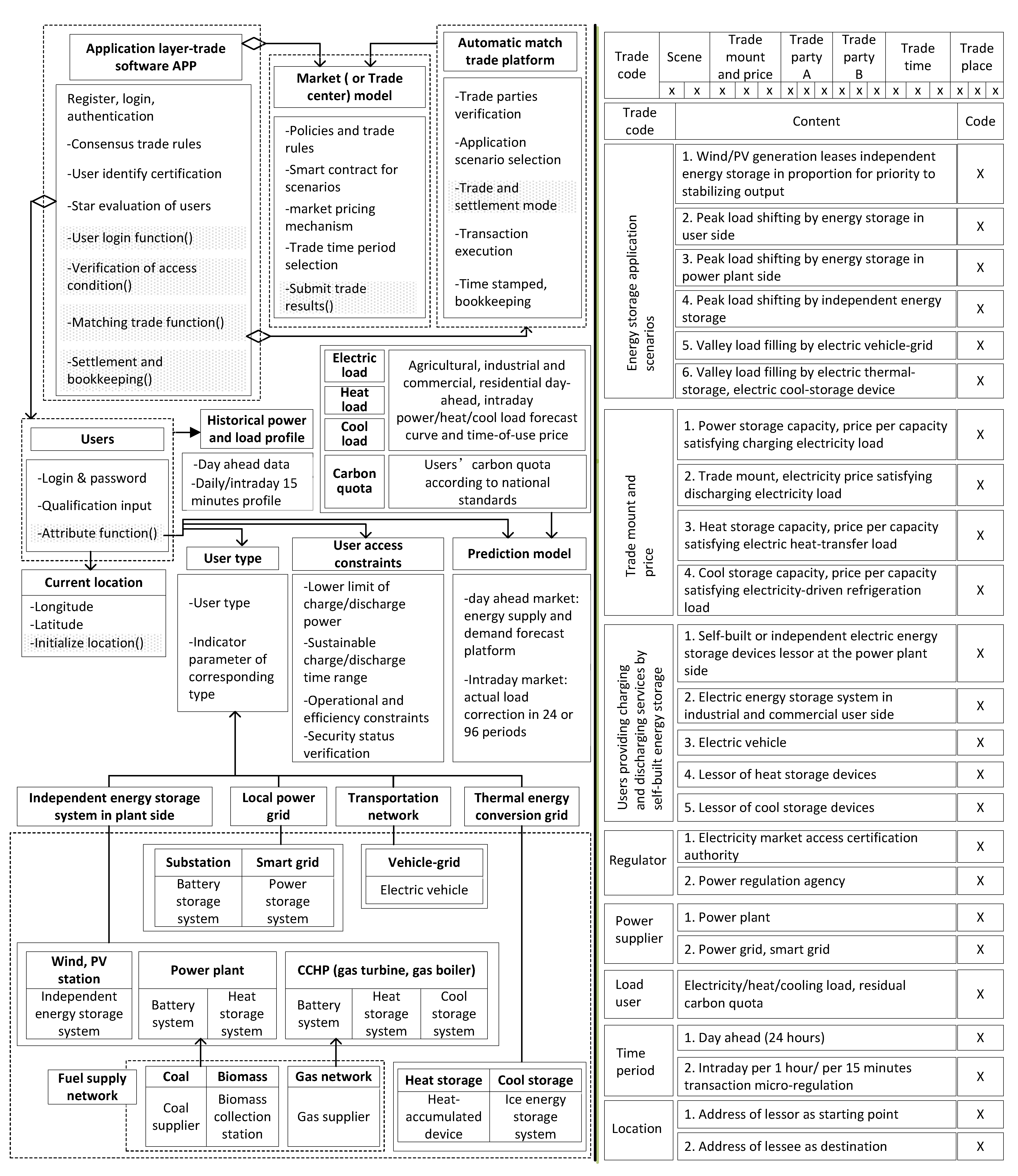
Wind/PV generation is given proportional priority in the rental energy storage services. Wind/PV generation leases shared energy storage facilities and electric vehicle charging to store extra electric output. The rental capacity is regarded as similar to its virtual self-built energy storage capacity, at a proportion of no less than 10% of the total capacity, for which the continuous charging time is no less than 2 h.
(2)
In peak-load shifting, as performed by energy storage devices on the user side, the user side builds electric energy storage devices for self-use and participation in the peak-load shift market trade. During peak-load periods, the user side needs the electric energy storage devices and V2G electric vehicles to discharge for load demand. The charged electricity is traded by the previous valley-load or current market electricity price. When discharging, energy storage devices and V2G can sell electricity, similarly to distributed power generation, to nearby users. The discharge price is settled according to the independent energy storage price stipulated by the territorial government.
(3)
In peak-load shifting by energy storage devices on the power-plant side, during valley-load time periods, electric storage devices built/owned by the power plant are leased to other power plants preparing for peak-load shifting by valley-load charging by signing transaction contracts, or as an independent energy storage entity participating in the peak-load shifting market to improve the frequency regulation performance of other power units. The amount of discharged electricity is equal to the amount of electricity generated at the power plant, and settled according to national standards of price.
(4)
In peak-load shifting by independent electric energy storage, smaller independent electric energy storage suppliers participate in the peak-load shifting transactions of energy storage capacity as the main body of the market, and submit information to nearby local power dispatch departments. The charging and discharging state of energy storage devices are uniformly regulated by the local power dispatch department. The charging electricity is settled by peak and valley electricity price, or purchased at an appointed valley price. When discharging, it is similar to distributed power generation, selling electricity to users in the near area, and the discharge price is settled according to the independent energy storage price stipulated by national standards.
(5)
Electric vehicles fill grid valleys. In night valley-load periods, electric vehicle charging is required to fill the valley. The vehicle network system regulates and displays the valley price information and signals the surplus power of the geographically nearest charging station or pile on the platform, so as to guide the electric vehicle to the nearest station or pile for charging. The charging amount complies with the charging price of electric vehicle stipulated by the government. For electric vehicles with special V2G functions, the independent energy storage price settlement stipulated by the national standards is used when discharging.
(6)
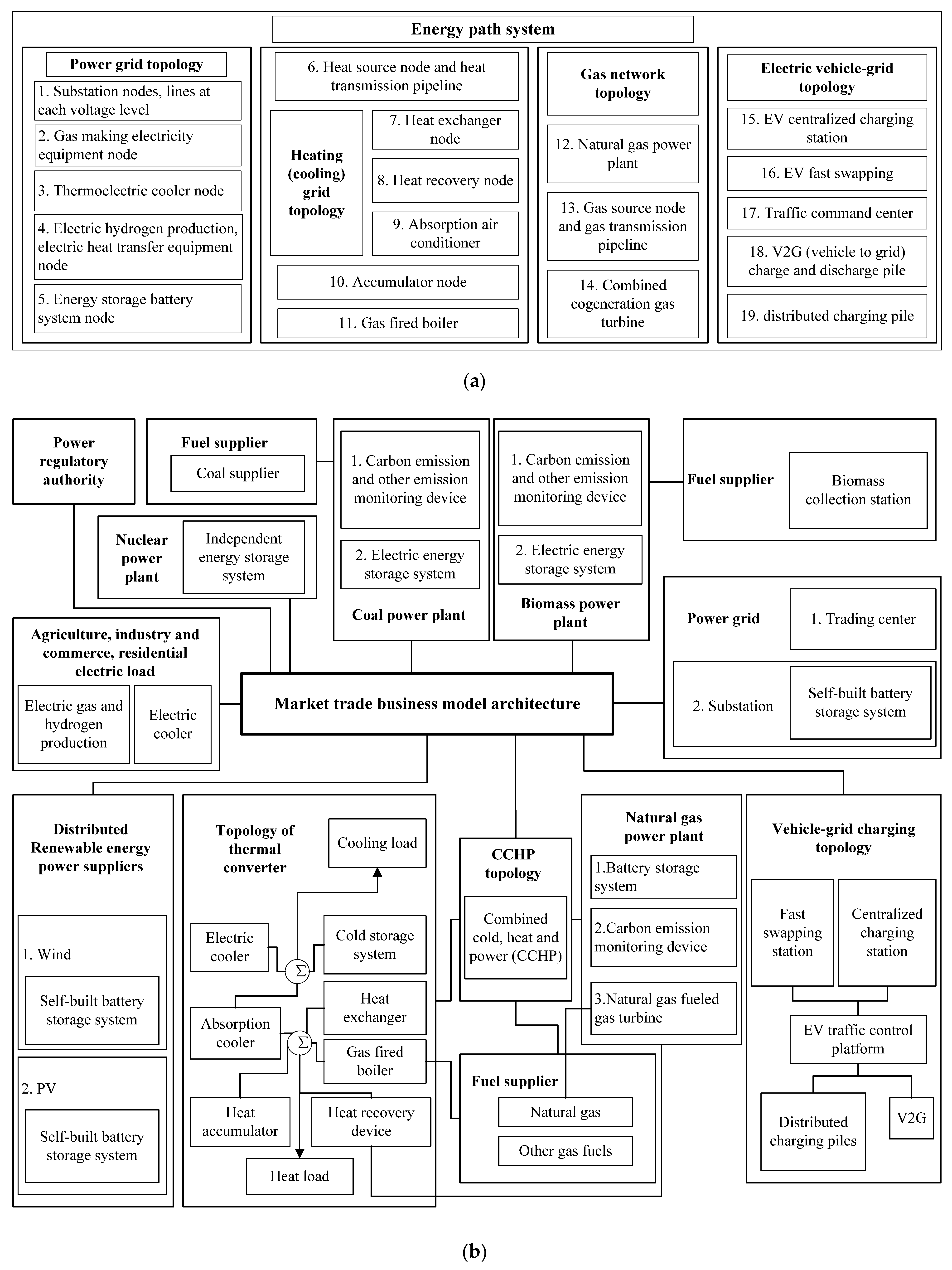
Valley-load electric heat storage, electric cold storage and thermal cold storage. The valley-load electric heat storage, electric cold storage and a heat-and-cold storage structured heat (cold) network topology is composed of heat-source nodes, heat-recovery device nodes, heat-exchange device nodes, electric heating equipment nodes, absorption refrigerator nodes, electric refrigerator nodes, micro gas turbine nodes, gas boiler node and heat (cold) transmission pipelines. Electric heat storage, electric refrigeration, and other heat storage (cooling) should be used when the electricity price is high during the day, so as to reduce the electricity cost of direct heating and cooling during the day.
Concerning carbon emission rights, the remaining carbon quota is measured according to standards of national carbon emission quotas and participates in carbon quota trading according to the requirements of the carbon-trading market. The smaller independent energy storage devices, who set quotes based on self-operating profit, can offer quotes within the scope of a national floating standard.
We present the trading capacity matching method of day-ahead and intraday markets, in which appointments are made for each scenario in the day-ahead market after uploading the supply and demand capacities and quoted energy storage suppliers, including electricity/hot/cold energy storage suppliers, and two or three energy storage demands at the same time. Micro-adjusting the actual supply and demand capacity occurs in 1-h and 15-min increments each day. If the capacity on the supply side is less than the actual capacity on the current demand side, when the supply side cannot provide new capacity, the system will continue to provide at least two options in the near area for the buyer to choose until all transactions on the demand side are completed; if the reserved capacity on the supply side is greater than the actual capacity on the current demand side, only the actual used capacity will be measured. In order to avoid the demand side increasing the forecast demand in the day-ahead market, the range of acceptable error rate and penalty are formulated in the contract. The error rate = (predicted value − actual value)/actual value × 100%, and the range of acceptable error rate is set to ±10%. For the period exceeding the error rate, a penalty of 5‰ should be paid in 24hours of the day.

3.2. Load Model of Charging and Discharging Distributed Energy Storage

3.2.1. Electric Vehicle (EV)

There have been 2,356,657 EVs recorded in the national regulatory platform between 2017 and 2019, of which blade electric vehicles (BEV) account for 84.6%, plug-in hybrid electric vehicles (PHEV) account for 15.3%, and fuel cell electric vehicles (FCEV) account for 0.01% [49]. The disorderly charging behavior of EVs will create harmonics, aggravating the peak–valley load difference and increasing grid loss. The factors affecting the temporal and spatial distribution characteristics of EVs’ charging and discharging are as follows: different EVs types, fast- or normal-charging mode of charging facilities, EVs users’ behavior, number of different types of EVs, environment temperature, and time-of-use price. The EV charging power is assumed to be uniformly distributed U(a, b). The initial state of charge (SOC) is assumed to be normal distribution N(μ, σ). The detail modelling process is as follows.
(1)
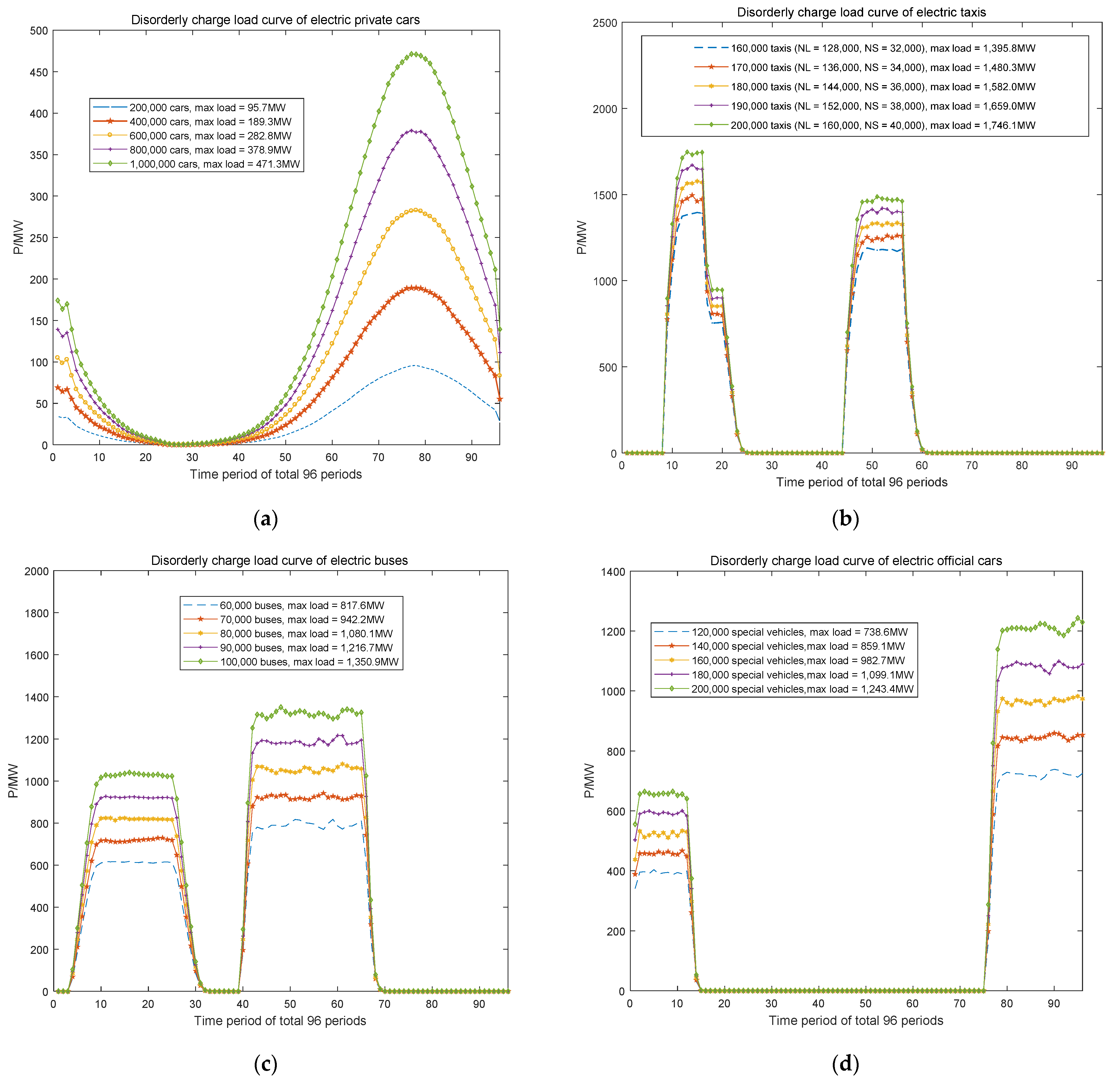
Respectively obtain the charging time probability of buses, private cars, taxis, and official vehicles, charging power, charging time, and discharge probability and time within the preset time period. Obtain a daily 15-min cumulative charging load and discharge power of all types of EVs.
According to the national standard of China GB/T 20,234, shown in Table 1, fast-charging mode adopts DC, with a maximum voltage of 750/1000 V and the maximum currents of 80/125/200/250 A, i.e., the charging powers from 60 kW through 250 kW. The normal charging mode adopts AC, with the maximum voltage 440 V and the maximum current 16/32/63 A, i.e., the charging powers from 7.04 kW through 27.72 kW.
Taking the taxi operation in Beijing, China, as examples, large-class taxi drivers shift every 24 h and small-class taxi drivers shift every 12 h. The ratio of large class to small class is about 4:1. The large class taxi drivers have a long rest and can choose normal charging, satisfying U(14.08, 27.72) (referring to Table 1) at public charging piles in residential or commercial areas. The small-class taxi drivers have a short rest time, and generally charge in fast mode, satisfying U(80, 250) (referring to Table 1). They charge twice a day, respectively, 2:00–5:00 am (the 8th through 20th time period) and 12:00–14:00 pm (the 48th through 56th time period) for large class taxi, and 2:00–4:00 am and 12:00–14:00 pm for small-class taxi. The battery capacity is assumed to be uniformly distributed under U(80, 100). The SOC is assumed to be normally distributed under N(0.5, 0.1). The charging time length, T (number of time periods), is calculated as follows, where CEV is the battery capacity (kW·per time period), η is the charging efficiency 0.8–0.9, and Pcharge is the charging power (kW).
T = ( 1 SOC ) · C EV η · P charge
(2)
According to the probability distribution simulating the type of EV and its charging behavior, randomly sample the charge power, battery capacity, SOC, charge starting time of each EV. Then calculate charging time duration and charging end time. Finally, calculate cumulative charge load curve for 96 time periods.
The battery capacity of private cars follows a uniform distribution, U(20, 30), as does slow-charging power, U(4, 6). Considering that the expectation of the probability distribution at the beginning of charging of private cars is 17.6 h, the variance is 3.4. The expectation of the initial state of charge is 0.6, while the variance is 0.2. The charging efficiency is 0.9. The mean value of the probability distribution of mileage is 3.2, and the variance is 0.88. Figure 3a depicts the load curves of private cars of different sizes during disorderly charging as the number of vehicles grows from 200,000 in 2020 to 1,000,000 in 2025.
Similarly, the disorderly charging load curves of electric taxis, buses, and special vehicles are respectively shown in Figure 3b–d.
The total charge load curve of the four types of EVs shown in Figure 4 includes the cars in Figure 3a, taxis in Figure 3b, buses in Figure 3c, and official and special vehicles in Figure 3d. The maximum charging power, 3425 MW, of EVs in 2025 in Figure 4 accounts for no more than 2.8% of current provincial peak load, about 123,810 MW in 2020.

3.2.2. Ice Storage System

Ice storage systems make use of the low electricity price at night to make ice and store it in an ice storage device. During the peak period of power consumption in the daytime, the ice melting releases its cooling capacity, which reduces the system cooling pressure during the peak load period and reduces the system’s operational cost. The main equipment of an ice storage system includes a refrigerator and an ice storage tank. Its working mode can be divided into separate cooling by the electric refrigerator, separate cooling by the ice storage tank, simultaneous cooling by the electric refrigerator and ice storage tank, and combined cooling by the electric refrigerator and ice storage tank. The electric load and cooling power curves of an ice storage system are shown in Figure 5.
Ice storage units can effectively use surplus power for refrigeration at night, transferring part of the power load at the peak of the day to the low-cost power period at night. The refrigeration host does not turn on, or turns on less, during peak times to reduce power load and improve the load composition of the power grid, which is conducive to the stable operation of the power grid.

3.2.3. Considering Demand Response

According to the power consumption characteristics of users and the operation time and energy consumption demand of different electrical equipment, power loads can be divided into uncontrollable loads, transferable loads, and interruptible loads.
Uncontrollable loads have no energy storage characteristics; the power consumption time is relatively fixed or may use power at any time according to the users’ wishes, such as lighting load, or load from TVs, computers, etc. Their operation time or power fluctuation range are small and basically without ability to transfer load. Transferable loads owe to equipment with or without energy storage characteristics, but whose power consumption periods are flexible. Washing machines and timed rice cookers do not have energy storage, but they use electricity flexibly, and, as their total power consumption is certain, they have load transfer capacity. Interruptible loads, obtain from equipment such as air conditioners and water heaters, have flexible power consumption characteristics and short-term power-off operation without great impact on users, but they may deviate from the original power consumption habits, such as by causing room and water temperature changes. For more on the operational model of integrated controllable load, we refer the reader to [50]. The response curve of a controllable load is shown in Figure 6, below.
According to the Chinese national standard of residential electricity, each family uses maximum 6 kW as the basic design capacity for ordinary residential living in a 61–100 m2 house. The power of the washing machines is generally 0.7–1 kW. The power of the timed rice cooker for a family having six persons is generally 0.8–1 kW. The power of an air conditioner with a heating function is generally 1.1–1.5 kW and there are typically 2–3 air conditioners for a large family. The power of the water heater is generally 1.2–2 kW. All household appliances always don’t use electricity at the same time, to avoid tripping circuit breakers. Thus, for a family, the transferable load, including a washing machine or a timed rice cooker, is about 0.7–1 kW. The interruptible load including an air conditioner or a water heater is about 1.1–1.5 kW.
Supposing there are 93 million people in a province, and every six persons form a family, we can deduce that there are about 15.5 million households in a province. Assuming the maximum load transfer of 20,000 households is 9 MW during the 45th–48th period, 14 MW during the 66th–68th period, and 8.4 MW during the 79th–84th period, we deduce that, ideally, there are about 6975 MW, 10,850 MW, and 6510 MW load transfers at three peak load periods, respectively. For residential interruptible loads, from 10:00 to 12:00 am, shutting down two air conditioners, or only one from 15:00–19:00 pm can reduce peaking load. In Figure 6c,d, if the maximum interrupted load of 20,000 households is 22 MW in the 47th–48th period and 7.5 MW in the 74th–76th period, we deduce that, ideally, there are about 17,050 MW and 5813 MW for a province. Thus, there are about maximum 24,025 MW over 11:30–12:00 am, 10,850 MW over 16:00–16:30 pm, 5813 MW over 18:30–19:00 pm, and 6510 MW over 19:45–21:00 pm in terms of demand response. During the maximum demand response load, the transferable and interrupted load accounts for 29% and 71%, respectively.

3.2.4. Heat Storage System

Heat storage devices can adjust the heating load through the process of repeatedly cycling heat storage and heat release.
The general energy storage system adopts the two charging and discharging cycles of “valley charging and peak discharging” and “flat charging and peak discharging”, every day, to reduce the times of charging and discharging to ensure the service life of the energy storage device. Three different types of heat storage devices are selected for the project, and the heat storage power and capacity meet the normal distribution. The expected values are configured as 1 MW/4 MWh, 2 MW/8 MWh, and 4 MW/12 MWh accounting for 1/3. At the same time, the heat storage exothermic conversion rate of the heat storage device is 0.92, and its heat storage/exothermic efficiency is 0.90. The initial heat storage state and the initial time of heat storage/exothermic efficiency follow different uniform distributions. By changing the total number of heat storage devices to 100, 200, 300, 400, or 500, the disordered charge–discharge curves of heat storage devices in different scales can be obtained from Figure 7a–d, respectively.

3.2.5. Decentralized Electrochemical Energy Storage

Under the time-of-use price proposed by the power grid company, industrial users adopt electrochemical energy storage devices because of their advantages of high energy density, fast response, and low maintenance cost [51]. The user-side energy storage uses the peak valley price difference to obtain income, namely, charging in the low electricity price period and discharging in the peak period to profit between peak and valley electricity prices. The total installed capacity of electrochemical energy storage in a province from 2021 to 2025 is about 480 MW, 1680 MW, 3840 MW, 6000 MW, and 8400 MW, respectively by year, and a decentralized system of 1 MW/2 MWh accounts for 40%, of 2 MW/5 MWh account for 40%, and of 6 MW/36 MWh accounts for 20%. In order to make use of the price differences between peaks and valleys, under two-charge and two-discharge modes, the optimal strategy is to charge the energy storage in the valley period of 0:00–8:00 am every morning and in the normal period of 12:00–14:00 pm, and discharge with a total duration of 4h during the peak period of 10:00–12:00 am and 14:00–16:00 pm every day. The 35% of full charging and discharging load curves of 200, 700, 1600, 2500, and 3500 devices are shown in Figure 8a,b, respectively.
In a sample case, the maximum discharging load is 8243 MW and the maximum charging load is 7462 MW in full charging and discharging mode, resulting in reduced battery life. In a realistic case, to protect battery life, a 30–40% charging and discharging mode is adopted. In the sampled 35% case, the maximum discharging load is 2942 MW and the maximum charging load is about 2671 MW.

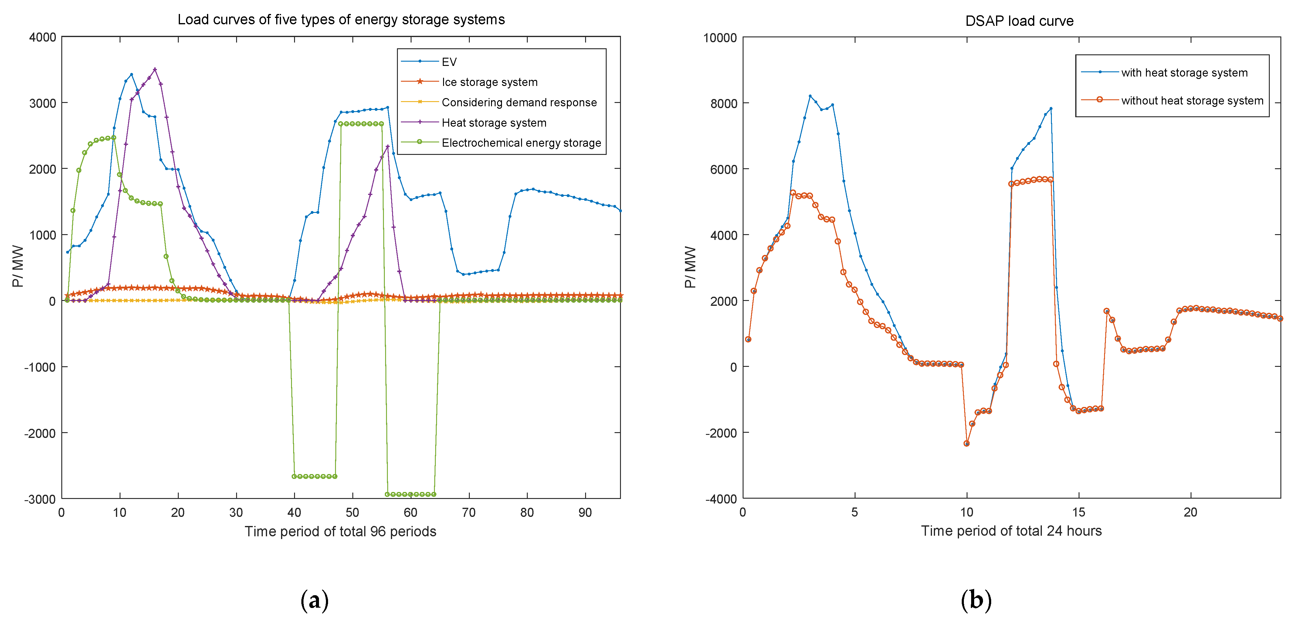
3.2.6. Distributed Storage Aggregation Provider (DSAP)

A DSAP is an independent organization that integrates all kinds of distributed energy storage resources and provides them to market buyers. As an intermediate organization in the distributed energy storage and power grid for providing power resources, it extracts, evaluates, and integrates distributed energy storage resources through professional means, integrates decentralized energy storage into system-schedulable resources, and participates in the operation of the power system.
The grid regulation takes reducing the variance of load curve and reducing the peak load as its charging and discharging objectives when dispatching and managing distributed energy storage. In order to reduce the negative impact of distributed energy storage on the power grid, combined with the time of use price mechanism, the goals of reducing the peak-to-valley difference of loads and reducing peak load can be set. A day is divided into 24 time periods-hours-and the optimization variable is the charge and discharge power of energy storage equipment in each time period.
In Figure 9a, EVs are the main charging load for the basic load curve in the period of 2:00–6:00 a.m. and 12:00–14:00 p.m., accounting for 65% and 52%, respectively, leading to an increased maximum load of 5167–5260 MW at 2:15–3:00 a.m. and of 5526–5670 MW, without a heat storage system, at 12:00–13:45 p.m., as shown in Figure 9b, corresponding to the electricity prices of 0.3052 yuan/kWh and 0.6104 yuan/kWh in Table 2, respectively. Until 2025, considering the heat storage system in summer, an extreme and unrealistic case for evaluating extreme maximum loads, the total increased maximum load of five energy storage systems between 6226–8209 MW at 2:15–3:00 a.m. and 6012–7829 MW at 12:00–13:45 p.m. accounts for 5–7% of Guangdong’s unified regulation load of 123,810 MW in 2020.

4. Impact on Power Grid Capacity, Load Characteristics, and Safety Margins

4.1. Distributed Energy Storage System on Load Side

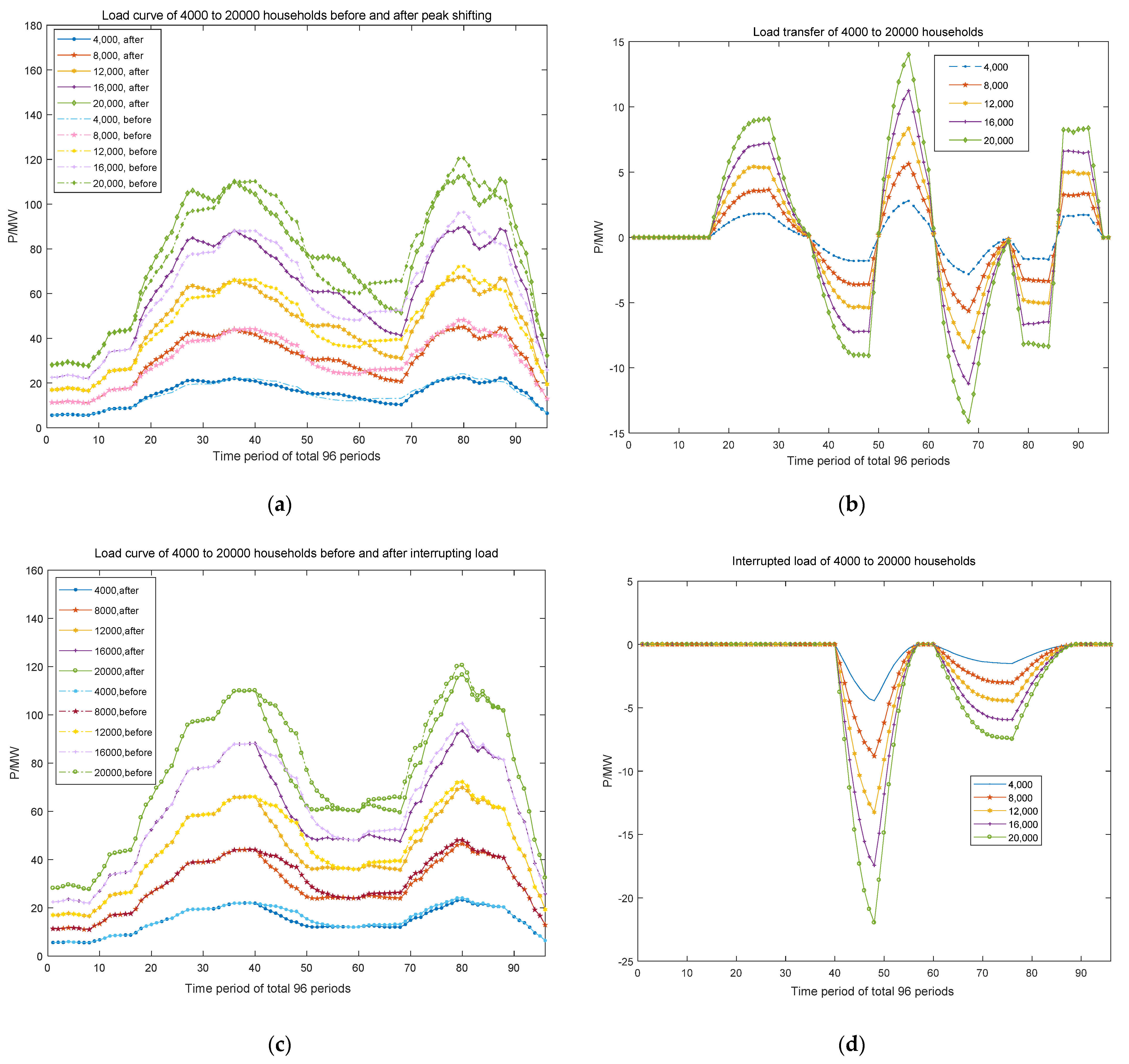
4.1.1. Impact on Peak Shifting, Energy Efficiency, and Economic Benefit for Consumers

The construction of power grid needs to meet the demand of peak load, resulting in low asset utilization and operational efficiency. Especially in summer, more than 40% of the grid load is air-conditioning load, while its annual power consumption is less than 10%. In Figure 9b, without considering heat storage systems until 2025, if the basic load is 123,810 MW in 2020, according to energy storage planning, using distributed energy storage for peak shifting of 1359–2353 MW at 10:00–12:00 a.m. and of 1024–1338 MW at 14:00–16:00 p.m., valley filling of 2314–5260 MW at 1:00–5:00 a.m. and a flat period fulfilling 5526–5670 MW at 12:00–14:00 p.m. can transfer no more than 1–2% of peak load, which increases to 4–5% load in valley and flat periods.
If the power consumption on a peak-load day is 2,000,000 MWh, the total charging and discharging power consumption of four energy storage systems without heat storage systems, depicted in Figure 9b, are 43,224 MWh and 4691 MWh, accounting for 2.2% and 0.23% of the daily consumption, respectively. The net increased daily power consumption is 38,533 MWh, accounting for 2% of the daily consumption. The net increased daily power consumption includes rigid power demand of EVs and energy loss of electrochemical battery system, may cause reduced energy efficiency.
According to rough estimation, the total power fee in the peak load day is 20.73 million yuan at the charging period, and a maximum 4.30 million yuan at the discharging period, as decided by the proportions at the user side, the power grid, and the supplier side. If the electrochemical battery capacity of the user side accounts for 7% of all distributed electrochemical energy storage in 2025, the total saving cost for users on a peak-load day is about 0.3 million yuan.

4.1.2. Impact on Safety Margin

The disorderly charging behavior of large volumes of EVs increases in risk until 2025, although the maximum charging power, 3425 MW, of the EVs simulated in Figure 4 accounts for no more than 2.8% of current provincial peak load, and 52–65% of energy storage load. For five types of energy storage, although the whole energy storage system flattens the single peak at 10:00–12:00 a.m. and 14:00–16:00 p.m., it forms multiple sub-peaks at 1:00–5:00 a.m. and 12:00–14:00 p.m. Although the risk level, at peak periods, of exceeding the limit decreases, the number of multiple sub-peak risks increases.
The orderly charging behavior of electrochemical energy storage invested in by the power grid, in case of emergency, can avoid overloading some equipment and of having low voltage of some nodes. In this case, the energy storage equipment put into operation at such critical moments can play the role of emergency support.

4.1.3. Impact on Planning and Construction Considering EVs

The power demand of EV batteries, accounting for 65% of charging power in the valley period and influenced by their work mode, affects the distribution grid planning, substation capacity, and equipment selection. The site selection of a substation is selected in combination with the distribution of EV charging load. The fixed capacity of the substation refers to the determination of the main transformer capacity of the substation, and the appropriate transformer capacity load ratio shall be considered. The simultaneous rate of conventional load peaks and EV charging load peak have an important impact on the determination of transformer capacity load ratio. With the growth of EVs, the uncertainty of charging load leads to the maximum load prediction deviation, requiring great changes of total substation capacity and layout.
If a large number of EVs are charged at widely distributed charging piles, the voltage waveform of a 380 V public bus will be seriously distorted because the piles are distributed in a 400 V low-voltage distribution system. The short-term fast charging of charging equipment may cause too fast a load change, produce impulse voltage, and endanger the safety of the power grid. In order to ensure power quality, on the one hand, corresponding active-filter and reactive power-compensation devices can be equipped. On the other hand, when planning to build a large-capacity charging station, it may not share the same section of bus with loads sensitive to power quality. The uncertain characteristics of EV charging time add uncertain factors to the power flow calculation of distribution system. In order to meet safe transmission requirements under various operation modes, a certain margin can be reserved for the line capacity. The weak links can be strengthened to ensure that the line current does not exceed the limit. When considering the impact of EV development on distribution network planning, the analysis of planning operational cost is more important. It is necessary to optimize the economic model in the planning process, so that the actual planning scheme can take into account adaptability and economy.

4.2. Distributed Energy Storage System on Power Resource Side

4.2.1. Impact on Stabilizing Output Power of Renewable Energy

In order to reduce the impact of clean energy output fluctuation on the power grid, installing appropriate distributed energy storage can increase the controllability of clean energy output power and stabilize power fluctuation to ensure the safe, stable, and economic operation of the clean energy grid with high permeability.
Based on power grids’ operational requirements, the objectives of stabilizing the output fluctuations of energy storage devices fall into three categories. The first category has the lowest requirements. When the power system’s operational conditions and regulation capacity are certain, it is expected that the grid connection of clean energy will not affect dynamic stability or cause frequency regulation pressure, that is, the output can meet the fluctuation constraints and frequency regulation requirement. The second type has an additional and more stringent requirement that the power generated by clean energy be able to track the power generation plan in real time. The third category has the highest requirements; the expected output must not only quickly respond to changes in power grid frequency and have the abilities of system frequency modulation and peak shaving, but also have a certain schedulability and the ability to coordinate large-scale clean energy generation.

4.2.2. Improving Clean Energy Consumption

We next consider the impact on the clean energy consumption of the power grid under various application modes, such as the joint configuration of a distributed energy storage system and flexible interconnection devices, and on participation in the demand response.
(1)
The joint configuration of distributed energy storage system and flexible interconnection devices. Compared with separate construction, the integrated construction mode of soft open point (SOP) and energy storage realizes the effective reuse of two groups of high-capacity power electronic converters in SOP, improves the utilization rate of SOP equipment, and greatly reduces the system construction investment and operation costs. From the perspective of operation, the addition of energy storage elements improves the operational inertia of SOP devices and enhances the ability of SOP devices to deal with transient disturbances in maintaining system energy balance for adapting to more complex operational scenarios and control requirements. From the perspective of the distribution grid, SOPs containing energy storage will have the energy transfer capability in both spatial and temporal dimensions, which can not only realize the real-time adjustment of transmission power between different feeders or stations, but also realize the functions of stabilizing fluctuation, peak shifting, and valley filling within a given time period, further strengthening the dispatching control capability of SOPs and improving the level of intermittent energy consumption. They will play an important role in improving power supply quality and optimizing the operation level of the distribution network. The dual role of SOPs with energy storage means they face higher technical requirements. In the planning stage, the investment cost and operation cost of SOP including energy storage will be closely related to the capacity and power of energy storage elements and the operation life under different charge and discharge strategies, which need to be fully considered; in terms of operation control, the charging and discharging of energy storage elements need to be completed by the cooperation of two groups of converters in the SOPs, which greatly increases the complexity of the control strategy. In addition, when the DC-side voltage level of SOPs is high, the energy storage components may need to be connected through DC chopper boosting, and the coordination among multiple power electronic converters will also become one of the key issues.
(2)
Distributed power generation combined with a distributed energy storage system participating in demand response. Photovoltaic output is concentrated in the daytime, the fluctuation amplitude and frequency of which are significantly greater. Wind power output fluctuates all day, but the overall output at night is large, having a negative effect in valley periods. Wind and solar grid connections reduce peak load, greatly reduce the overall time series curves, and increases the capacity margin. The net load curve has multiple valleys, and the net load in valley periods can even be negative. In order to avoid the phenomenon of abandoning wind and PV, the main network and other distributed energy sources need to have downward regulation capacity and reserve capacity. In some periods, the wind power output and load trends are inconsistent, resulting in large fluctuation times and amplitude of the net load curve, which requires the system to have a flexible climbing ability.
In order to improve the consumption level of clean energy and avoid the phenomenon of abandoning wind and PV when the net load is negative, distributed energy storage can be charged during valley periods and discharged during peak load periods. Through the time sequence transfer of the net load curve, the energy utilization rate of uncontrollable distributed generation can be increased, to avoid the phenomena of abandoning wind and PV power and high-price power purchasing under the low acceptance capacity of the system.

5. Conclusions

There is a developing trend of establishing a hierarchical and partitioned-energy internet sharing operation platform to gather wind power, photovoltaic, energy storage, flexible load, heat and cold energy systems, and energy suppliers to realize consumer energy services. The energy interconnection and sharing platform of Dongguan’s local dispatching was established in 2017 and put into operation in 2019. Based on cloud–edge computing technology, it has realized the pioneering construction of distributed cloud energy storage with access to a local power grid management platform. Although the current market policy has not been liberalized, the platform performs only power monitoring and operation and the maintenance of power load equipment and does not have the functions of heat energy collection, carbon emission monitoring, or market transaction. However, with the progress of technology and the attention of the national industry, it will further realize such a platform with ideal functionality.
Building a local dispatching platform of the provincial demand side’s response platform has great significance for consolidating new power system infrastructure for carbon peaking and carbon neutralization and for improving the efficiency of comprehensive energy management. Our suggestions are as follows:
(1)
Though energy storage has many advantages, there are some focuses: single-peak load shifting transferring to multiple sub-peak loads; lower energy efficiency, as electricity increase in valley periods are much greater than the reductions of peak loads; the high cost of electrochemical batteries; EV load demand accounting for more than 60% of increased energy storage load and needing a regulated work mode; unnecessary heat load and replaceable and interruptible load implemented by setting enterprise rules.
(2)
The grid company should propose standards of energy storage configuration, improve the features of the proportion of storage capacity, such as location and operational and maintenance measures, and configure energy storage access to the sharing platform.
(3)
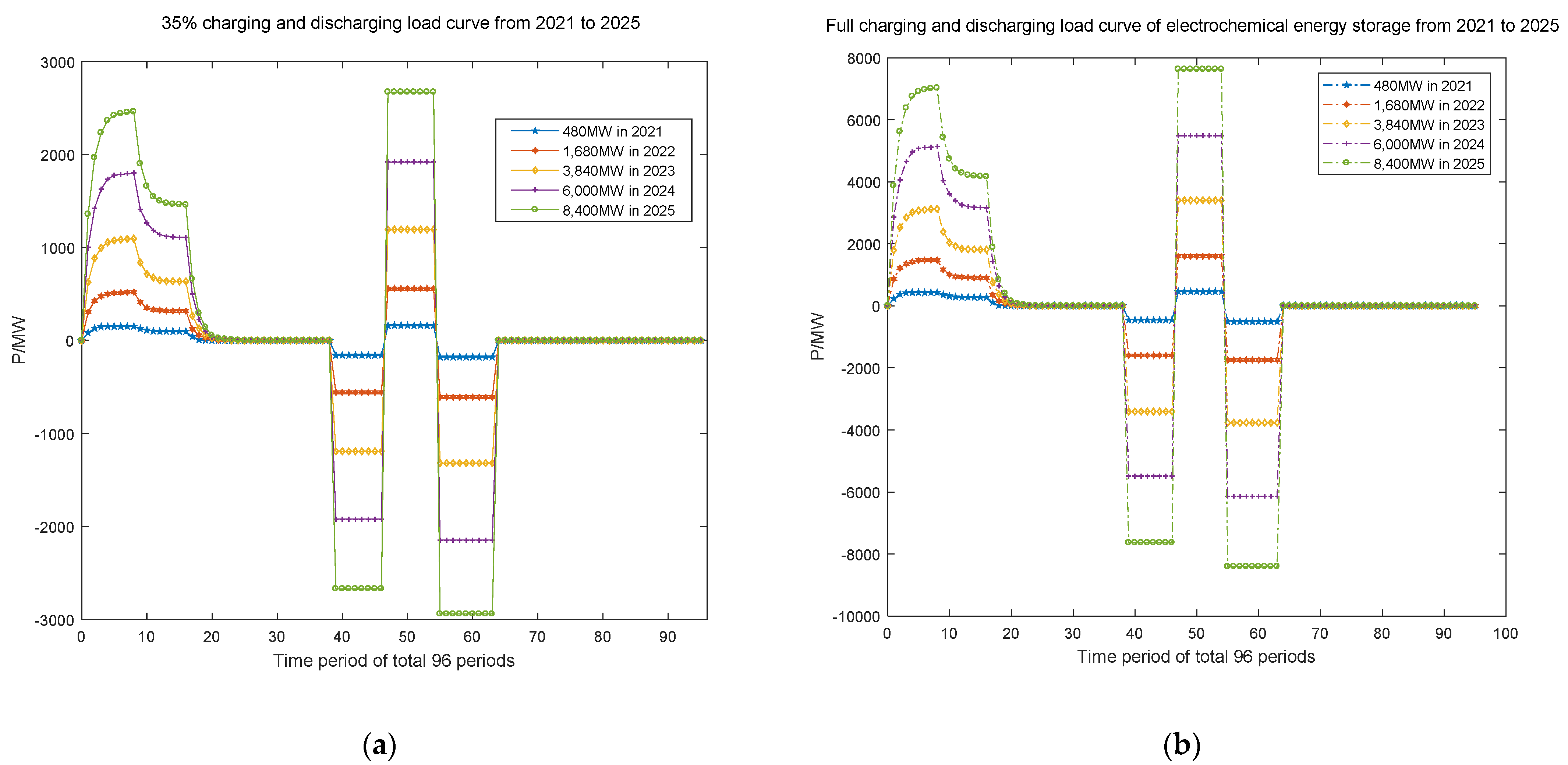
Electrochemical energy storage has the fastest response and highest cost. At present, in order to protect battery service life, realistic operation requires shallow charging and discharging, of about 30–40% in one charging. It is not necessary to plan a too-large overall capacity scale on the power-supply side, power-grid side, or user side in the next five years; rather, we recommend such installed capacity only when other measures cannot solve overload problems.
(4)
Control the power demand of users. It is necessary to make mandatory management rules for energy conservation and emission reduction, such as controllable air conditioning and heating load.

Author Contributions

Conceptualization, J.L. and Y.X.; methodology, J.L., Y.X. and D.Z.; software, Y.X., D.Z. and J.L.; validation, D.Z., Y.X. and J.L.; formal analysis, Y.X., J.L. and D.Z.; investigation, J.L. and D.Z.; resources, Y.X.; data curation, Y.X. and J.L.; writing—original draft preparation, J.L. and Y.X.; writing—review and editing, J.L.; supervision, J.L. and D.Z.; project administration, J.L. and Y.X.; funding acquisition, J.L. All authors have read and agreed to the published version of the manuscript.

Funding

This research was funded by China Southern Power Grid Company Limited Science and Technology Project Foundation (030000KK52190010 (GDKJXM20198116)).

Institutional Review Board Statement

Not applicable.

Informed Consent Statement

Not applicable.

Acknowledgments

Thanks to the researchers in Sichuan Energy Internet Research Institute, Tsinghua University, who helped provide the source code and some analysis contents. We would like to express our gratitude to them for their help and guidance.

Conflicts of Interest

The authors declare no conflict of interest.

References

  1. Liu, J.; Zhang, N.; Kang, C.; Kirschenb, D.; Xia, Q. Cloud energy storage for residential and small commercial consumers: A business case study. Appl. Energy 2017, 188, 226–236. [Google Scholar] [CrossRef] [Green Version]
  2. Liu, J.; Zhang, N.; Kang, C. Research framework and basic models for cloud energy storage in power system. Proc. CESS 2017, 37, 3361–3371. [Google Scholar]
  3. Zhou, L.; Huang, Y.; Guo, K.; Feng, Y. A survey of energy storage technology for micro grid. Power Syst. Prot. Control 2011, 39, 147–152. [Google Scholar]
  4. Chen, W.; Shi, J.; Ren, L.; Tang, Y.; Shi, Y. Composite usage of multi-type energy storage technologies in microgrid. Autom. Electr. Power Syst. 2010, 34, 112–115. [Google Scholar]
  5. Awerbuch, S.; Preston, A. The Virtual Utility: Accounting, Technology & Competitive Aspects of the Emerging Industry; Springer: New York, NY, USA, 2012. [Google Scholar]
  6. Mashhour, E.; Moghaddas-Tafreshi, S.M. Bidding strategy of virtual power plant for participating in energy and spinning reserve markets—Part I: Problem formulation. IEEE Trans. Power Syst. 2011, 26, 949–956. [Google Scholar] [CrossRef]
  7. Ghavidel, S.; Li, L.; Aghaei, J.; Yu, T.; Zhu, J. A Review on the Virtual Power Plant: Components and Operation Systems. In Proceedings of the 2016 IEEE International Conference on Power System Technology (POWERCON), Wollongong, Australia, 28 September–1 October 2016; pp. 1–6. [Google Scholar]
  8. Kempton, W.; Tomić, J. Vehicle-to-grid power implementation: From stabilizing the grid to supporting large-scale renewable energy. J. Power Sources 2005, 144, 280–294. [Google Scholar] [CrossRef]
  9. Tuttle, D.P.; Baldick, R. The evolution of plug-in electric vehicle-grid interactions. IEEE Trans. Smart Grid 2012, 3, 500–505. [Google Scholar] [CrossRef]
  10. Han, S.; Sezaki, K. Development of an optimal vehicle-to-grid aggregator for frequency regulation. IEEE Trans. Smart Grid 2010, 1, 65–72. [Google Scholar]
  11. Tan, X.Q.; Yang, S.C.; Fang, Y.P.; Xue, D. Discussion on operation model to the electric vehicle charging station. AMR 2014, 875–877, 1827–1830. [Google Scholar] [CrossRef]
  12. Li, J.; Zhou, S.; Lu, X. Planning method and principles of the cloud energy storage applied in the power grid. In Proceedings of the 2020 IEEE Sustainable Power and Energy Conference (ISPEC), Chengdu, China, 23–25 November 2020; pp. 2040–2046. [Google Scholar]
  13. Mu, L.; Cui, L.; An, N. Research and Practice of Cloud Computing Center for Power System. Power Syst. Technol. 2011, 35, 171–175. [Google Scholar]
  14. Rao, W.; Ding, J.; Lu, Q. Cloud Computing Platform Construction for Smart Grid. East China Electr. Power 2011, 39, 1493–1496. [Google Scholar]
  15. Bai, Y.; Huang, Y.; Chen, S.; Zhang, J.; Li, B.; Wang, F.-Y. Cloud-edge Intelligence: Status Quo and Future Prospective of Edge Computing Approaches and Applications in Power System Operation and Control. Acta Autom. Sin. 2020, 46, 397–410. [Google Scholar]
  16. Jin, W. Research on Distributed Storage Convergence and Coordination Control Strategy. Master’s Thesis, China Electric Power Research Institute, Beijing, China, June 2018. [Google Scholar]
  17. Guo, B.; Niu, M.; Lai, X.; Chen, L. Application research on large-scale battery energy storage system under Global Energy Interconnection framework. Glob. Energy Interconnect. 2018, 1, 79–86. [Google Scholar]
  18. Jin, R.; Zhang, X.; Wang, Z.; Sun, W.; Yang, X.; Shi, Z. Blockchain-Enabled Charging Right Trading Among EV Charging Stations. Energies 2019, 12, 3922. [Google Scholar] [CrossRef] [Green Version]
  19. Yao, W.; Zhao, J.; Wen, F.; Xue, Y.; Xin, J. A charging and discharging dispatching strategy for electric vehicles based on bi-level optimization. Autom. Electr. Power Syst. 2012, 36, 30–37. [Google Scholar]
  20. Hu, W.; He, L.; Chen, J. A bi-layer optimization based schedule considering large-scale electric vehicles. Power Syst. Prot. Control 2016, 44, 22–28. [Google Scholar]
  21. Zhang, Q.D.; Huang, X.L.; Chen, Z.; Chen, L.X.; Xu, Y.P. Research on control strategy for the uniform charging of electric vehicle battery swapping station. Trans. China Electrotech. Soc. 2015, 30, 447–453. [Google Scholar]
  22. Liu, W.; Wen, F.; Ma, L.; Xue, S. Demand-side Transactive Energy Mechanism Considering Electric Vehicles and Controlable Loads. Electr. Power Constr. 2019, 40, 24–30. [Google Scholar]
  23. Vasirani, M.; Kota, R.; Cavalcante, R.L.G.; Ossowski, S. An Agent-Based Approach to Virtual Power Plants of Wind Power Generators and Electric Vehicles. IEEE Trans. Smart Grid 2013, 4, 1314–1322. [Google Scholar] [CrossRef] [Green Version]
  24. Fan, S.; Liu, J.; Wu, Q.; Cui, M.; Zhou, H.; He, G. Optimal coordination of virtual power plant with photovoltaics and electric vehicles: A temporally coupled distributed online algorithm. Appl. Energy 2020, 277, 115583. [Google Scholar] [CrossRef]
  25. Wang, H.; Chen, S.; Yan, Z.; Ping, J. Blockchain-enabled charging right trading among EV charging stations: Mechanism, model, and method. Proc. CSEE 2020, 40, 425–435. [Google Scholar]
  26. Jin, Z.; Wu, R.; Li, G.; Yue, S. Transaction model for electric vehicle charging based on consortium blockchain. Power Syst. Technol. 2019, 43, 4362–4369. [Google Scholar]
  27. Zhang, F.; Li, G.; Wang, T. Electric vehicle charging chain based on blockchain technology. Comput. Technol. Dev. 2020, 30, 161–166. [Google Scholar]
  28. Yang, Y.; Peng, D.; Wang, W. Block-chain based Energy Tracing Method for Electric Vehicles Charging. In Proceedings of the 2020 IEEE Sustainable Power and Energy Conference (iSPEC 2020), Chengdu, China, 23–25 November 2020; pp. 2622–2627. [Google Scholar]
  29. Zhang, X.; Yang, Y.; Su, S. Study on Electric Vehicle Sharing and Leasing Business Model for Group Users based on Blockchain. In Proceedings of the 2020 IEEE Sustainable Power and Energy Conference (iSPEC 2020), Chengdu, China, 23–25 November 2020; pp. 2628–2633. [Google Scholar]
  30. Tapscott, D.; Tapscott, A. Blockchain Revolution; Tap Publications Inc.: New York, NY, USA, 2016. [Google Scholar]
  31. Di Silvestre, M.L.; Gallo, P.; Guerrero, J.M.; Musca, R.; Sanseverino, E.R.; Sciumè, G.; Vásquez, J.C.; Zizzo, G. Blockchain for power systems: Current trends and future applications. Renew. Sustain. Energy Rev. 2020, 119, 109585. [Google Scholar] [CrossRef]
  32. Nakamoto, S. Bitcoin: A Peer-to-Peer Electronic Cash System. Consulted. 2009, pp. 1–9. Available online: https://www.bitcoin.org or http://www.spacepirates.com/bitcoin.pdf (accessed on 30 March 2009).
  33. Ferrag, M.A.; Derdour, M.; Mukherjee, M.; Derhab, A.; Maglaras, L.; Janicke, H. Blockchain Technologies for the Internet of Things: Research Issues and Challenges. IEEE Internet Things J. 2019, 6, 2188–2204. [Google Scholar] [CrossRef] [Green Version]
  34. Yang, D.; Zhao, X.; Xu, Z.; Li, Y.; Li, Q. Developing Status and Prospect Analysis of Blockchain in Energy Internet. Proc. CSEE 2017, 37, 3664–3671. [Google Scholar]
  35. Wang, S.; Guo, C.; Feng, B.; Zhang, H.; Du, Z. Application of blockchain technology in power systems: Prospects and ideas. Autom. Electr. Power Syst. 2020, 44, 10–24. [Google Scholar]
  36. Yuan, Y.; Wang, F. Blockchain: The state of the art and future trends. Acta Autom. Sin. 2016, 42, 481–494. [Google Scholar]
  37. Zhang, J.; Gao, W.Z.; Zhang, Y.C.; Zheng, X.H.; Yang, L.Q.; Hao, J.; Dai, X.X. Blockchain based intelligent distributed electrical energy systems: Needs, concepts, approaches and vision. Acta Autom. Sin. 2017, 43, 1544–1554. [Google Scholar]
  38. Zhang, N.; Wang, Y.; Kang, C.; Cheng, J.; He, D. Blockchain Technique in the Energy Internet: Preliminary Research Framework and Typical Applications. Proc. CSEE 2016, 36, 4011–4022. [Google Scholar]
  39. Zeng, M.; Cheng, J.; Wang, Y.; Li, Y.; Yang, Y.; Dou, J. Primarily research for multi module cooperative autonomous mode of energy internet under blockchain. Proc. CSEE 2017, 37, 3672–3681. [Google Scholar]
  40. Dong, Z.; Luo, F.; Liang, G. Blockchain: A secure, decentralized, trusted cyber infrastructure solution for future energy systems. J. Mod. Power Syst. Clean Energy 2018, 6, 1–10. [Google Scholar] [CrossRef] [Green Version]
  41. Cui, J.; Wang, S.; Xin, Y. Research on technical framework of smart grid data management from consortium blockchain perspective. Proc. CSEE 2020, 40, 836–848. [Google Scholar]
  42. Tai, X.; Sun, H.; Guo, Q. Electricity transactions and congestion management based on blockchain in energy internet. Power Syst. Technol. 2016, 42, 2630–3638. [Google Scholar]
  43. Ouyang, X.; Zhu, X.; Ye, L.; Yao, J. Preliminary applications of blockchain technique in large consumers direct power trading. Proc. CSEE 2017, 37, 3737–3745. [Google Scholar]
  44. Ma, T.; Peng, L.L.; Du, Y.; Gou, Q.F.; Wang, C.; Guo, X.F. Competition game model for local multi-microgrid market based on block chain technology and its solution algorithm. Electr. Power Autom. Equip. 2018, 38, 191–203. [Google Scholar]
  45. Li, B.; Cao, W.; Zhang, J.; Chen, S.; Yang, B.; Sun, Y.; Qi, B. Transaction system and key technologies of multi-energy system based on heterogeneous blockchain. Autom. Electr. Power Syst. 2018, 42, 183–193. [Google Scholar] [CrossRef]
  46. Wang, B.; Li, Y.; Zhao, S.; Chen, H.; Jin, Y.; Ding, Y. Key technologies on blockchain based distributed energy transaction. Autom. Electr. Power Syst. 2019, 43, 53–64. [Google Scholar]
  47. Qi, B.; Xia, Y.; Li, B.; Li, D.; Zhang, Y.; Xi, P. Photovoltaic trading mechanism design based on blockchain-based incentive mechanism. Autom. Electr. Power Syst. 2019, 43, 132–139. [Google Scholar]
  48. Wang, Y.; Li, J.; Hu, Y. Research on Integrated Energy Trading Mechanism Based on Blockchain Smart Contract Technology. In Proceedings of the 2020 IEEE Sustainable Power and Energy Conference (iSPEC 2020), Chengdu, China, 23–25 November 2020; pp. 2634–2639. [Google Scholar]
  49. National Big Data Alliance of New Energy Vehicles (NDANEV). The National Regulatory Platform for New Energy Vehicles Has Accessed 2.357 Million New Energy Vehicles, with a Driving Mileage of 27.42 Billion Kilometers. 2019. Available online: http://www.china-nengyuan.com/news/141934.html (accessed on 9 July 2019).
  50. Gao, H.; Wang, L.; Liu, J.; Wei, Z. Integrated day-ahead scheduling considering active management in future smart distribution system. IEEE Trans. Power Syst. 2018, 33, 6049–6061. [Google Scholar] [CrossRef]
  51. Jiang, K.; Li, H.; Li, W.; Cheng, S. On several battery technologies for power grids. Autom. Electr. Power Syst. 2013, 37, 47–53. [Google Scholar]
Figure 1. The architecture of a market trade business: (a) energy path system; (b) market trade business model architecture.
Processes 10 00194 g001
Figure 2. Unified model architecture for trade participators, flowchart and trade code.
Processes 10 00194 g002
Figure 3. The disorderly charging load curve of EVs: (a) private cars; (b) taxis; (c) buses; (d) official and special vehicles.
Processes 10 00194 g003
Figure 4. The total charging load curve of private cars, taxis, buses, and official and special vehicles.
Processes 10 00194 g004
Figure 5. An ice storage system: (a) electric load curve of ice storage system; (b) cooling power of an ice storage system.
Processes 10 00194 g005
Figure 6. The response curve of 4000 to 20,000 household loads. (a) Transferable load curve before and after peak shifting and valley filling; (b) load transfer curve; (c) interrupted load curve before and after interrupting load; (d) interrupted load curve.
Processes 10 00194 g006
Figure 7. Electrical load curve of a heat storage system: (a) curve of a type 1 (1 MW/4 MWh) heat storage device; (b) curve of a type 2 (2 MW/8 MWh) heat storage device; (c) curve of a type 3 (4 MW/12 MWh) heat storage device; (d) comprehensive heat storage load curve of a heat storage device.
Processes 10 00194 g007
Figure 8. The charging and discharging load curves of the planned capacity of electrochemically stored energy from 2021 to 2025: (a) 35% charging and discharging; (b) full charging and discharging.
Processes 10 00194 g008
Figure 9. The load curve of distribution energy storage systems in 2025: (a) charging electric load curves of five types of energy storage systems; (b) DSAP total charging power load curve including EVs and ice storage, considering demand response and a decentralized shared system on a day using heat storage systems (in winter) and without the use of heat storage systems (in summer).
Processes 10 00194 g009
Table 1. Different EV charging modes according to national standard of China GB/T 20,234.
Charging ModeAC/DCMaximum Voltage (V)Maximum Current (A)Maximum Power (kW)
L1 (slow charging)AC25010/16/322.5/4/8
L2 (normal charging)AC44016/32/637.04/14.08/27.72
L3 (fast charging)DC750/100080/125/200/25060/93.75/150/187.5 or 80/125/200/250
Table 2. The electricity price of large industrial power in Guangzhou, China, in its distribution grid.
Peak and Valley Time PeriodClassification of Load VoltagePrice (RMB yuan/kWh)
flat load (8:00–10:00, 12:00–14:00, 19:00–24:00)1–10 kV0.6104
20 kV0.6072
35–110 kV0.5854
peak load (10:00–12:00, 14:00–19:00)1–10 kV1.0072
20 kV1.0019
35–110 kV0.9659
valley load (0:00–8:00)1–10 kV0.3052
20 kV0.3036
35–110 kV0.2927
Publisher’s Note: MDPI stays neutral with regard to jurisdictional claims in published maps and institutional affiliations.

