
Flow Modeling in a Vortex Chamber of a Liquid–Steam Jet Apparatus


1
Department of Technical Thermophysics, Sumy State University, 2 Rymskogo-Korsakova St., 40007 Sumy, Ukraine
2
Department of Computational Mechanics Named after Volodymyr Martsynkovskyy, Sumy State University, 2 Rymskogo-Korsakova St., 40007 Sumy, Ukraine
3
Department of Chemical Engineering and Apparatuses, Poznan University of Technology, 4 Berdychowo St., 60-965 Poznan, Poland
4
Department of Manufacturing Engineering, Machines and Tools, Sumy State University, 2 Rymskogo-Korsakova St., 40007 Sumy, Ukraine
5
Department of Mathematics, Anand International College of Engineering, D-40 Shanti Path, Jaipur 303012, India
*
Author to whom correspondence should be addressed.
Processes 2022, 10(5), 984; https://doi.org/10.3390/pr10050984
Submission received: 27 January 2022
/
Revised: 16 April 2022
/
Accepted: 11 May 2022
/
Published: 16 May 2022
(This article belongs to the Collection Modeling, Simulation and Computation on Dynamics of Complex Fluids)
Abstract
:The article investigated the flow of boiling streams through a nozzle with an oblique cut. Due to this flow organization, deviation from the nozzle axis at the vortex chamber inlet occurred. The study of flow modeling in the inlet section was carried out. The flow design and the calculation scheme of the vortex liquid–steam jet apparatus were proposed. Analytical expressions between the main operating parameters were obtained according to the developed mathematical model. A recommended oblique-cut angle for the active-flow nozzle was evaluated considering the transition through the first critical section based on the tangential velocity flow model. Validation of the mathematical model in the inlet section of the vortex chamber was provided based on the comparison with available experimental data. Flow visualization in the inlet section of the vortex chamber was obtained. The assumption of uneven flow distribution was confirmed experimentally. Overall, the boiling liquid flow was implemented in the active flow nozzle. The obtained scientific and practical results help to determine geometric parameters and physical characteristics of the vortex-type liquid–steam jet apparatus at the design stage. The obtained results were implemented to modernize vacuum units based on vortex type liquid–steam jet apparatuses.
1. Introduction
Recently, a few industries have had the need to use vacuum systems. Simultaneously, these systems should have high productivity and should provide a moderate increase in the pressure of the vacuum medium. Due to the mentioned above, the ability of vortex jets to self-vacuum is of particular interest. Such an ability allows for the development of corresponding vortex vacuum pumps. Vacuums created in such devices provide intensive pumping of gas from the vacuumed volume due to creating a vacuum area near the axis of the device.
Jet devices are used to pump mixtures, liquids, and gases, to create and maintain a vacuum, and to mix liquid, solid and gaseous media [1]. Since their creation, significant progress has been made in improving the design of devices and in developing calculation techniques that extend the area of their practical application. However, expanding the functionality of jet devices, including vacuum purposes, is an urgent scientific problem.
The authors of [2] investigated the fundamentals of creating a calculation technique and analyzing boundary modes of the vortex-type liquid–steam jet apparatus (LSJA). The thermodynamic model of the operational process in LSJA of a vortex type is based on the following equations: the Navier–Stokes equations in cylindrical coordinates; state equations for a two-phase medium; mass conservation equation; phase transition equation; energy conservation equation; momentum conservation equation; entropy equation; equation of phase transition kinetics; equation of liquid droplets distribution by size; dependencies for sound speed in a two-phase medium, channel geometry, and shear stress near the wall.
The analysis of advanced research shows that the study of the operational process, the creation of a thermophysical model, and methods for calculating vortex-type LSJA are critical issues that have practical significance. Simultaneously, in designing LSJA, it is necessary to create an appropriate calculation technique. Unlike direct-jet jet devices, simulation of the vaporization process for adiabatic vortex flows is a more complicated problem due to the dominance of inertial forces in the mechanism of origin and growth of the vapor phase.
Moreover, the efficiency of an LSJA largely depends on the perfection of the leakage and formation of the operating steam jet. Therefore, to convert the energy of unheated liquid to saturation and to use the boiling stream as an operating fluid, it is necessary to study adiabatic vaporization in the vortex flow. In this regard, the impact of the oblique cut of the active flow nozzle should be considered.
Significant achievements in liquid–steam jet devices were obtained while studying the jet thermal compression principle in direct-jet devices. Flow dynamics in a convergent–divergent nozzle water jet were simulated in [3]. The authors in [4] also presented a numerical approach to simulate decompression expansion of subcritical flow through a converging–diverging nozzle. In [5], differences between homogenous and heterogenous models of two-phase compressible flow in a heat pump ejector were investigated.
In [6], adiabatic flowing streams in nozzles were considered. As a result, the impact of regular characteristics on relaxation steam formation was studied. In addition, an approach for multidimensional modeling two-phase ejector flow was proposed in [7]. An analysis of the possibility of using water as a refrigerant for a heat pump based on a liquid–vapor ejector was provided in [8].
These seam jet devices have the following disadvantage: they need a separate steam generator and water purification system to create working steam. However, in the proposed liquid–steam jet devices, the generation of working steam occurs directly in the boiling liquid. In addition, the study of using the jet thermal compression principle in heat pumps based on liquid–steam jet devices is known [9].
Moreover, a three-dimensional CFD simulation of flashing flows in a converging–diverging nozzle was realized in [10]. As a result, a pressure recovery process was studied. Finally, experimental studies and numerical simulations of cavitation behavior in water-jet processing were realized in [11].
Overall, this article aims at expanding the functionality of LSJA by investigating the process of boiling liquid in a vortex flow. The following research objectives are formulated to achieve this goal: determination of the design scheme of the flow in the vortex-type LSJA considering boundary conditions, assumptions, and limitations for the proposed model; the development of a mathematical model for the operating flow in a vortex-type LSJA; issuance of recommendations in ensuring the needed oblique cut angle for the nozzle, depending on the transition through the first critical section; validation of the mathematical model for flow boiling in an inlet section of a vortex chamber; verification of the assumption about an uneven distribution of the flow structure; practical implementation of research results in the practice of compressor equipment design.
Models of flow motion considering energy exchange with the external environment and its dissipation within the operating volume are based primarily on studying quasi-equilibrium approximations of actual processes [12]. In this case, the irreversibility of actual processes is considered by introducing empirical coefficients, mainly the velocity coefficients of flowing parts [13].
Many researchers contributed to designing energy-efficient equipment based on the vortex flow and jet steam apparatuses. Takahashi et al. [14] proposed the evaluation method for steam dryer loading. As a result, it was proved that normalization by dynamic pressure is an effective means for the evaluation of fluctuating pressure in stub pipes. Xu et al. [15] analyzed the impact of steam on the hydrodynamic characteristics of vortex flow. As a result, the numerical calculation approach for identifying modified coefficients was proposed. In addition, Li and Wei [16] numerically simulated a gas-injected cyclone separator by a fluid–solid coupling algorithm. As a result, the optimal choice of the air–water balance pressure was substantiated for the case of the gas injection chamber.
Additionally, Sadeghiseraji et al. [17] studied the impact of the Mach number on hydrodynamic characteristics of a vortex tube using different turbulence models. As a result, features of the internal flow were simulated using CFD analysis. Gnatowska et al. [18] studied flow stability in cylindrical chambers. As a result, the influence of the Reynolds number on spacing limits was substantiated for the unstable flow modes.
Rogovyi et al. [19] proposed the methodology of optimal designing vortex chambers. As a result, the maximum hydrodynamic characteristics of the vortex chamber were reached. In addition, Symak et al. [20] studied the dissolution kinetics of dispersed systems under pneumatic mixing. As a result, hydrodynamic characteristics were analyzed using the locally isotropic turbulence theory.
Tseitlin et al. [21] carried out the thermal analysis of the technological equipment based on hot gas emission. As a result, the heat exchange characteristics of trays for concentrating solutions in direct contact with hot gas emissions were improved. Bondar and Vaneev [22] studied the operational process in a vortex expansion machine. Experimental research proved the efficiency of using side channels compared with peripheral ones.
After considering the previous results, the following research gaps in designing a vortex-type liquid–steam jet apparatus have been formulated. First, a thermophysical model of a fluid boiling under centrifugal forces for a vortex apparatus operating on boiling liquid should be formulated and proven. This approach clarifies the physical model of the operating processes in the liquid–steam jet apparatus of a vortex type. Second, experimental characteristics of the vortex-type liquid–steam jet apparatus should be obtained. Finally, the influence of the oblique cut of the active flow nozzle on the formation of the vortex flow in the liquid–steam jet apparatus of the vortex type should be theoretically substantiated and experimentally confirmed. This approach allows for the development of oblique-cut nozzles to ensure smooth twisting of the flow.
2. Materials and Methods
2.1. Characteristics of Operating Processes
The peculiarity of designing vortex apparatuses is that there are two areas in the vortex flow. In the area from the axis to a certain radius, the flow rotates at almost constant angular velocity ω = const (i.e., according to the rotation law for a rigid body). This area is called a forced vortex. In the peripheral region, the angular velocity decreases sharply by radius. In this area, the velocity change law is close to the potential flow of a liquid or gas. This area is called a free vortex [23]. Notably, the circulation remains constant for any closed circuit covering the rotation axis and zero for other circuits.
A literature review on adiabatic boiling of a liquid in centrifugal forces has shown that such studies have been almost non-existent. However, research works on the study of heat transfer during boiling of a liquid in the field of centrifugal forces for non-cryogenic liquids (e.g., freon, ethanol) are known. Studies of boiling for cryogenic liquids (e.g., hydrogen, nitrogen, helium) have also been conducted. However, primary attention was paid to studying cooling systems for superconducting windings of rotors in cryoturbodetanders. Notably, in works on studying heat transfer at boiling in the field of centrifugal forces of cryogenic and non-cryogenic liquids, a heater was used to provide a single boiling center. Accordingly, the boiling process was carried out using heat supplied from the heater.
The design scheme of the operating processes in the vortex-type LSJA is presented in Figure 1.
In Figure 1, the following processes occur: 4′–5—increase in the fluid pressure of the active stream; 5–1—heating of the active stream fluid; 1–s0—expansion of the flow in the nozzle of the active stream; s0–a—pressure drop in the active stream nozzle to overcome the state of fluid metastability; a–2—the process of adiabatic boiling of a liquid in a vortex flow; 2–3, pas–3—mixing of active and passive flows in the process of vortex motion; 3–4—increase in the pressure of the mixed flow; 4–4′, 4–4″—flow distribution into liquid and vapor phase.
Notably, p01—the pressure of the operating fluid of the active stream; ps0—fluid pressure in the flow cross-section; pa—flow pressure at the outlet of the nozzle; p02—passive steam vapor pressure; pmix—the pressure of the mixed vortex flow; x—the degree of dryness of the steam. In addition, the relative initial underheating of the active stream fluid is equal to (p01–ps0)/p01.
According to Figure 1, an operating process in a vortex-type LSJA is supplying unheated liquid to the nozzle of the active stream and creating a vortex flow of the vapor–liquid mixture. Passive flow steam injections are realized by an operating vortex flow along the axis of the vortex chamber. In this case, mixing of the injected passive and active media is carried out in the formed vortex flow. In the outlet of the vortex chamber, there is a compression of the mixed flow. Afterward, it is divided into liquid and vapor phases. The position of point 1 is determined by the choice of pressure p01 and the level of heating the liquid ΔT = T1 − T5. In the process of leakage through the nozzles of the active stream 1–s0, the temperature of the medium of this stream does not change. It equals the temperature of the unheated liquid at the compression pressure p01. The pressure drops to the pressure of the pumped medium p02. The last one is always less than the compression pressure. Therefore, the liquid is metastably overheated. This fact leads to its intensive boiling and formation of a jet of an operating stream with high volume vapor content. Further, the flow enters the vortex chamber, where it becomes twisted.
Due to the tangential twist of the flow in the vortex chamber, the vortex flow of the vapor–liquid mixture is formed at the outlet of the active flow nozzle. The flow parameters are distributed over the radius of the vortex chamber. Simultaneously, a zone of reduced pressure is formed along the axis of the vortex chamber, due to which an injection of steam of a passive stream occurs. In the twisted flow, the liquid phase is distributed on the periphery of the vortex chamber and the vapor one through the axial direction. At the same values of the mass flow rate of the active flow, using the specified approach for compressing the vapor–liquid mixture, the vaporization time in the vortex flow decreases compared with the liquid–steam jet apparatus of the direct axis type. This determines the reduction of the influence of the scale factor on the mass and size of such devices [24].
In the case of a leak of boiling liquid from the nozzle with an expanding oblique cut, the flow is deflected relative to the nozzle axis and, accordingly, relative to the vortex chamber, bypassing the initial section of the twist. This effect ensures uniform flow distribution over the entire cross-section of the vortex chamber. Due to the deviation in the oblique cut, the flow hits the vortex chamber wall. This leads to its deformation and uneven distribution along the radius of the liquid and vapor phases and velocity fields and pressures in the initial section of the vortex chamber I-I. The uneven distribution of flow parameters occupies the area of the vortex chamber from the cross-section I-I to the cross-section II-II. After, there is an alignment of the flow and its transition to a steady mode.
2.2. The Design Schemes of Liquid–Steam Jet Apparatuses
The formation of the flow can occur in vortex chambers of various designs. Their main difference is the channel design for the inlet of active flow and the length of the cylindrical part of the vortex zone. Design features of the most well-known designs of active-flow inlet channels are presented in Table 1.
According to the chosen design scheme, the flow structure in the meridional plane at the inlet section I-I of the vortex chamber is considered (Figure 2).
According to experimental data carried out in work [25], the vaporization at the outflow of unheated liquid in the expanding channels occurs in the flow cross-section f on the wall, where conditions are created to form steam bubbles. In the near-wall bubble boiling area, the flow has a circular structure. Mainly, a metastable superheated liquid moves in the center. Additionally, a two-phase flow occurs in a thin near-wall layer. Low values of the sound speed characterize bubble or foam flow. Therefore, at a short distance from the flow cross-section f, the flow passes through the first critical section (*), which determines the final value of the initial metastable superheat of the liquid and the flow characteristics of the expanding nozzle. At the distance of zv from the initial cross-section of boiling, the transformation of the flow structure is completed. In cross-section v, the transition to the droplet flow occurs. Through the cross-section v, the flow passes through the second critical section (**) due to the sound speed exceeding the current value of the average speed c. In other words, the flow tends to the upper dispersion limit. Further extension of the flow and residual breakup of the largest droplets will occur in the vortex chamber of LSJA.
Due to the profiled flow supply at the vortex chamber’s inlet, the saturation pressure ps0 in the unheated liquid is established. It corresponds to the initial temperature t0 of the liquid. Since the liquid in section f is metastably overheated, and pressure pf is less than pressure ps0, and the boiling of the liquid is shifted deeper into the vortex chamber. Moreover, this effect occurs in an annular cross-section at a particular radius r* of the initial bubble boiling point. A section between the annular sections r1 and r* is due to the delay in forming active centers in the accelerated flow under large radial gradients of pressure and velocity.
In the initial cross-section of the vortex chamber I-I, the flow has a circular structure at the bubbling zone. Mainly, in the peripheral region, the metastable superheated liquid moves. Additionally, the bubble liquid is transferred to a fine two-phase environment (foam) in the axial region.
The intensive generation of steam bubbles in the field of centrifugal forces in the cross-section I-I is accompanied by their increase in volume and movement along the axis of the vortex chamber. Due to the uneven distribution of vapor content along the axial cross-section of the vortex chamber I-I, an unstable region of the bubble structure is observed. It does not change until the cross-section of a steady flow II-II. In cross-section II-II (at some distance from the cross-section I-I), the inversion of the flow structure is completed. As a result, the transition to a droplet flow is provided. Moreover, a residual breakup of large liquid droplets occurs. Simultaneously, after the cross-section II-II, the operating vortex flow of the steam droplet structure is completely formed.
2.3. A Mathematical Model
For a cylindrical vortex chamber, under the assumption that the layers do not mix in the radial direction (radial velocity component cr = 0), the flow parameters in the cross-section of the active-flow inlet I-I are described by the following system of Euler equations for a steady flow in cylindrical coordinates [26]:
The primary assumptions of the mathematical model are as follows. First, an axisymmetric flow along the entire length of the vortex chamber is considered . This assumption is based on studies of various constructions of the active flow inlet to the vortex chamber. It characterizes the stationary axisymmetric flow. Notably, axisymmetric flow along with the vortex chamber is confirmed for designs presented in Table 1, having at least two active flow inlets.
Second, the circular component of the absolute flow velocity cu(r) depends on the radius and does not depend on the longitudinal coordinate . This assumption shows that the angular component of the flow velocity remains unchanged along with the vortex chamber. This assumption is valid for vortex chambers with a length-to-diameter ratio of more than 1.
Finally, the axial component of the absolute flow rate cz(r, z) and pressure p(r, z) depends on the radius r and the longitudinal coordinate z. This assumption shows that the distribution of the axial component of the velocity and pressure of the stationary flow occurs simultaneously along with the axis and radius of the vortex chamber.
The continuity equation in cylindrical coordinates considering the compressibility of the flow [27] is as follows:
Given the assumptions mentioned above, Equation (1) takes the following form for a stationary axisymmetric flow:
The general integral of Equation (3) can be written as follows:
where f(r)—unknown function determined from the boundary conditions in the initial section I-I. First, when the value of the longitudinal coordinate z = 0, the vortex flow pressure pI-I = p(r, 0) = pI-I(r) is set in cross-section I-I. Second, under z = 0, the axial component of the vortex flow velocity cz(r, z) takes the form of cz = cz(r, 0) = cz0(r).
After the substitution of Equation (4) into Equation (3), the following condition is obtained:
Considering the boundary conditions for the initial cross-section I-I of the vortex chamber, Equation (4) is written as follows:
Considering these equations and eliminating the change in the axial component of the velocity along the length of the vortex chamber, it can be obtained:
where —the radial pressure gradient in the vortex flow.
Traditionally, the axial velocity component can be neglected for the inlet cross-section I-I of the vortex chamber (cz = 0). Therefore, according to the momentum conservation law [28], cu·r = const.
However, under conditions of the irreversibility of the expansion process, the momentum is changed. In this case, it is proposed to improve the model by the power dependence of the change in the circular velocity component, which characterizes the free vortex:
where n—empirical dimensionless parameter that characterizes the irreversibility of the expansion process.
The numerical value of this power depends on the geometric and operating parameters of the active flow. A method for evaluating it according to experimental studies is described below.
Considering the boundary conditions for the initial cross-section I-I of the vortex chamber, Equation (8) can be rewritten as follows:
After substitution into Equation (7), the separation of variables
and further integration within specified limits
the following expression can be obtained:
where —pressure difference.
For the most minimal case of an oblique cut at the vortex chamber’s inlet, saturation parameters are set in the active stream. Therefore, the following conditions can be acceptable: pI-I = ps0, , v = va, cu1 = ca, and r = r1.
Under the condition of the initial boiling point for the liquid in the vortex chamber, the dependence for determining the modified Euler number for the vortex flow is as follows:
where Δpmst—the required pressure difference to overcome the metastability of the liquid, which delays the initial boiling point; va—specific volume, m3/kg; ca—the average flow rate in the cross-section of the oblique cut.
Notably, the criterion in Equation (13) characterizes the following ratio between pressure forces per unit volume of a vapor–liquid mixture and inertial forces:
where φa = 0.97–0.98—velocity coefficient of a nozzle [2].
The average rate of equilibrium adiabatic process is as follows:
where , the enthalpies of steam and liquid in the cross-section of the nozzle in the saturated state, respectively; , —the entropies of the steam and liquid in the cross-section of the nozzle in the saturated state, respectively; Ta—the absolute flow temperature at the nozzle outlet.
After considering the above equations, Equation (13) can be rewritten:
This dependence obtains a universal dependence for relative radius of the initial bubble boiling point of the vortex flow in terms of the modified Euler number Eu*:
Thus, the obtained dimensionless relative radius of the initial bubble boiling point in the vortex flow is a radial parameter of the critical cross-section I-I for the vortex-type LSJA. This fact determines the process of the initial boiling point of a liquid in a vortex stream, which depends on the ratio between the pressure and inertial forces, physical properties of the fluid, and parameter n. The last one, in turn, depends on the geometric and operating parameters of the active flow.
2.4. Analytical Model
The stationary model has been considered for the following parameters. First, the solid parametric model had the following geometric dimensions: the critical cross-section diameter df = 4.1 mm; the oblique-cut angle is in the range of 20–60°; the taper angle is equal to 16°; the initial pressure 𝑝01 = 5 bar. In addition, the pressure of the environment after the oblique cut pa is less than pressure p01 before it. Additionally, during the simulation, equations according to the computational domain of the solid-state model [29] were used. Finally, the active flow working fluid (water) and multiphase calculation model were chosen from the ANSYS database.
The boundary conditions of the active flow traditionally include inlet (normal velocity), outflow (atmospheric pressure), and walls (Figure 2).
The Euler–Lagrange Discrete Phase Model (DPM) model simulates a multiphase flow. The carrier phase is modeled based on the Euler approach on a fixed grid, while the dispersed phase is based on the Lagrangian approach by tracking the trajectories of particles throughout the computational domain.
The carrier phase is modeled by numerically solving the system of the Navier–Stokes, and by the continuity equations [30]:
where u—flow velocity, m/s; t—time, s; p—pressure, Pa; ρ—flow density, kg/m3; ν—kinematic viscosity, m2/s; ∇—the gradient operator; ∇2—the Laplacian operator.
The trajectories of the dispersed phase are calculated on a given time interval after calculating the flow field of the carrier phase [31]:
where up—particle velocity, m/s; ρp—particle density, kg/m3; g—acceleration of gravity, m/s2; dp—average diameter of the particle, m; Ip—a moment of inertia, kg·m2; ωp—rotational velocity, rad/s; Cω—rotational drag coefficient, s−1; τr—relaxation time, s:
where μ—dynamic viscosity of the flow, Pa·s; Cd—drag coefficient; Re—Reynolds number.
The differential Equation (18) contains the following specific forces, N/kg: f1—added mass force, accelerating the flow around the particle; f2—thermophoretic force causing particles to move against a temperature gradient; f3—Brownian force as Gaussian white noise; f4—Saffman lifting force because of viscous shear stress; f5—Magnus force due to the rotation of the particle because of pressure gradient on its surface.
Equation (19) does not consider the fractional-order Basset force. However, its action on a droplet in a two-phase flow is valuable near the vibrational walls [32]. Nevertheless, in the considered design of the nozzle, all the walls are stationary.
3. Results
3.1. Experimental Results Data
Visualization of the flow through the transparent wall has been obtained on an experimental stand, the design scheme of which is presented in Figure 3.
The results have confirmed the uneven flow distribution in the inlet section I-I of the vortex chamber due to the deviation in the oblique cut of the nozzle (Figure 4).
The photo shows zones of uneven distribution of liquid and vapor phases around the circumference of the vortex chamber. Notably, the presence of a vacuum zone is observed.
3.2. Computational Model
For confirmation of the thermophysical and mathematical flow models from the expanding nozzle, the simulation and visualization of the flow were carried out in a previous study [24] using the ANSYS software.
During modeling, the following geometric parameters were used: internal diameter of the vortex camera—100 mm; length of the vortex camera—200 mm; critical cross-section diameter df = 4.1 mm; oblique-cut angle α = 20–60°; the taper angle of the nozzle α1 = 16°.
Depending on the modeling approach, multiphase flow models were divided into two main classes: Lagrange and Euler models. The Lagrange approach considers individual particles or their groups in the secondary dispersed phase. The Euler approach considers changes in thermal and kinematic flow parameters at each location. In this case, all phases are continuous, regardless of their shape. Moreover, the phase volume fraction concept is introduced for multiphase flows. However, hybrid models are applied based on alternate Lagrange and the Euler approaches in most cases. According to this approach, the averaging over space and the transition from the particle distribution to the phase volume fraction are provided.
The following mesh parameters [33] have been used during the simulation. The computational mesh includes a boundary layer created in the area of the oblique cut with the following settings: number of layers—6, growth rate—1.2, maximum thickness—0.15 mm. In addition, in the oblique-cut region and the area of the vapor–liquid flow outlet from the oblique-cut region, the mesh was refined using the “Sizing” option. Due to the increase in the element number in the flow core region and the near-wall region, these settings will make it possible to describe the process of liquid boiling (formation of a vapor phase) and the flow transition more accurately to the supersonic speed.
The mesh includes 1.8 × 10⁶ cells and characterizes them by the following quality parameters: minimum orthogonal quality 0.012 (with an acceptable value greater than 0.001) and maximum skewness 0.92 (with an acceptable value less than 0.95). During the analysis of mesh independence, it was found that with an increase in the mesh elements number of more than 1.6 × 10⁶, flow parameters, namely the velocity and pressure, change by less than 1%.
The “Homogeneous” model was chosen as a multiphase flow model since it is recommended to use in cases with multiphase flows and is less resource intensive than the “InHomogeneous” model. In addition, the “Cavitation” model was used to simulate the flow core process, namely, the liquid boiling and the formation of a vapor phase. The k-ε model was chosen as the turbulence model, with an additional setting: wall function—scalable. Water was chosen as the liquid phase and water vapor as the gaseous phase. The boundary conditions for the flow inlet were set as follows: initial pressure 0.5 MPa, the water volume fraction equal to 1.0, and the outlet pressure at 0 MPa. The total time for transient calculation was set to auto timescale, the time step to 1.0 × 10⁻⁴ s, and the convergence accuracy to 1.0 × 10⁻⁶. The y+ was in the range from 3 to 10.
3.3. Numerical Simulation Results
Numerical simulations using ANSYS software allowed us to obtain velocity contours in the longitudinal cross-section (Figure 5).
Figure 5 shows that the direction of the wave propagation from the lower edge of the oblique cut coincides with the theoretical description. Moreover, the obtained velocity fields correspond to the method of characteristics based on the use of physical laws of propagation in a supersonic flow of weak rarefaction and compression waves, as described in [29].
After modeling, lines of flow deviation from the nozzle axis were superimposed onto the obtained flow patterns. Experimental images have confirmed the results for the leakage of boiling liquid from the active-flow nozzle.
As a result, the recommended oblique cut angle values have been obtained. They are summarized in Table 2 depending on the transition through the first critical section.
According to the calculation results, if the angles of the oblique cut are more than 50°, the cross-section of the initial boiling point for the liquid is on the border of the oblique cut. Therefore, the flow does not pass through the first critical section within the oblique cut. This phenomenon leads to a shift in the boiling process deeper into the vortex chamber. Simultaneously, this increases the vaporization time and length of the vortex chamber to complete the vaporization process. For the angles in the range from 20° to 45°, the boiling of the liquid and the transition through the first critical section occur within the oblique cut. However, at oblique cut angles less than 40°, the flow deflection angle is significant. This fact leads to a shock of the flow on the walls of the vortex chamber and flow disturbance in the initial section.
Therefore, it is recommended to design oblique-cut nozzles with the angles of α = 40–45°. Such angles allow the flow to boil within the oblique cut and pass through the first critical section (*), and significant deviations do not occur.
The datasets of experimental data arrays on the impact of the modified Euler number on the change in the radius of the initial bubble boiling point in a vortex flow are presented in Figure 6.
3.4. Parameter Identification of the Mathematical Model
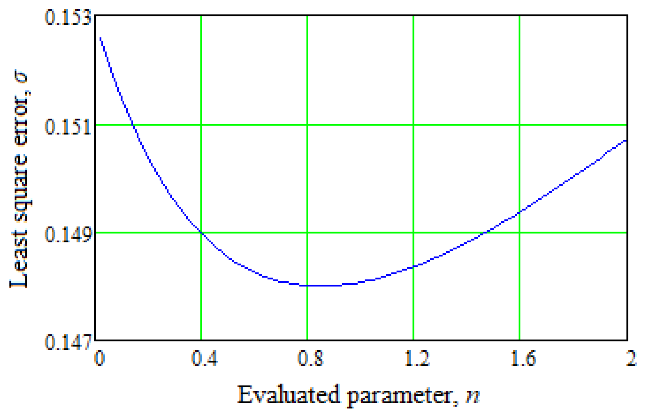
The regression procedure [34] has been applied to confirm the proposed mathematical model (17). This method is based on minimizing the normalized standard deviation of a theoretical curve with the available experimental data (Figure 6):
where , —experimentally obtained values of the modified Euler number and the dimensionless radius, respectively.
Notably, for the case of combining two datasets, as presented in Figure 6, the dependence (21) has a local minimum for a wide range of changes in parameter n (Figure 9).
Therefore, the parameter identification procedure is realized by Equation (21) and Figure 9. For this purpose, Equation (21) is used to evaluate the parameter n by minimizing the normalized standard deviation of the theoretical curve (17) with the experimental data (Figure 6).
Notably, for the considered case study, σ(n) = min = 0.148 for the value n = 0.85.
The obtained results confirm the following facts. First, on the periphery of the inlet section of the vortex chamber, there is a predomination of inertia forces, and on the axis, pressure forces. Second, increasing the Euler number decreases the initial bubble boiling point radius (Figure 6). Finally, an increase in relative initial underheating of the liquid leads to a shift in the initial boiling point to the periphery of the vortex chamber (Figure 8).
4. Discussion
Notably, the obtained results have eliminated the following research gaps in designing vortex-type liquid–steam jet apparatuses. First, a physical model of working processes in the liquid–steam jet apparatus of the vortex type has been developed based on the thermophysical model of boiling liquid in centrifugal forces.
Second, the obtained theoretical and experimental data has substantiated an impact in the oblique cut of the active-flow nozzle on the formation of the operating vortex flow.
Remarkably, the main results of [13] are as follows. The analytical dependence for the relative radius of the initial bubble boiling point in the vortex flow was obtained. In addition, the experimental research results for the expanding nozzle were obtained for the following discrete geometric parameters: the critical cross-section diameter df = 2.3 mm and 4.1 mm; values of the oblique-cut angle are 20°, 40°, and 60° only, and the taper angle is 16°; initial pressure range p01 = 5–20 bar. However, in the paper, the previous results have been substantially supplemented, mainly as follows:
- (1)
- a range for the angle δ of flow deviation depending on an arbitrary value of the oblique-cut angle αc has been extended, including a range of 20–60°;
- (2)
- a value of the main parameter n has been clarified based on the proposed analytical dependence (17);
- (3)
- the regression dependence interpolating dataset from Figure 6 has been obtained based on the experimental dependence of the dimensionless radius on the modified Euler number.
The advantages of the proposed method with previous works are as follows. Mainly, the structures of compressible vortex rings generated by the compressible starting jet from converging and diverging nozzles were studied in work [35]. However, that research does not allow the designing nozzles with an oblique-cut angle to ensure smooth flow twisting. Additionally, active flow control of the vortex rope and pressure pulsations in a swirl generator were proposed in [36]. However, our results have analytically substantiated the impact of oblique cut of the active-flow nozzle to form an operating vortex flow. Moreover, patterns for efficient propulsion during the energy evolution of vortex rings is presented in [37].
Nevertheless, the proposed approach substantiates the uneven distribution of liquid and vapor phases around the vortex chamber (i.e., the presence of a vacuum zone). Finally, an experimental study of jets in rotating flow fields is presented in [38]. Therefore, our approach allows authors to apply the mathematical model to obtain the primary thermophysical characteristics under centrifugal forces analytically.
The obtained results can also be partially implemented in designing vortex-type liquid–steam jet apparatuses [39], developing the up-to-date heat and mass transfer equipment [40], and ensuring rational designing jet apparatuses for environmental protection [41]. In addition, visualization of the boiling streamflow in the apparatus for obtaining the distributions of pressure, velocity, and phase transformations is planned to be realized soon.
Further plans for diminishing the stated problem are as follows. First, the obtained results improve the inlet geometry of the vortex chamber. Second, these results obtain regularities of the impact of initial thermal and geometric parameters on the efficiency of the vaporization process in a vortex flow.
Finally, refinement of the mathematical model of the relaxation vaporization process in the vortex flow will be realized. It should consider an oblique cut of the nozzle at the vortex chamber’s inlet, radial pressure gradient, spiral trajectories of the vortex flow, and the formation of an annular region of quasi-solid rotation and reverse flow zone.
5. Conclusions
The flow model with tangential velocity has been taken as the calculated flow model in a liquid–steam jet apparatus of the vortex type. In such modeling, the joint solution of Euler and continuity equations with given boundary conditions are considered. The design scheme of flow in the vortex type apparatus has been proposed considering all the boundary conditions, assumptions, and limitations.
During the study, the comprehensive methodology based on the consequent analytical approach in flow modeling using a system of Euler’s partial differential equations for a steady flow in cylindrical coordinates, CFD analysis by the ANSYS software, and the parameter identification of the proposed model by the regression procedure based on the best fit with the experimental results data has been applied.
As a result, the following primary findings have been obtained. First, the physical meaning of the operating process in the vortex-type LSJA has been clarified. Second, the main geometric parameters of the active flow nozzle with an oblique-cut angle have been specified. Finally, an analysis of the dimensionless relative radius of the initial bubble boiling point has determined the process of the initial boiling point of a liquid in a vortex flow.
The basic calculation equations of the operating process in the vortex-type apparatus using the flow model with tangential velocity were obtained. A value of the recommended oblique-cut angle for the active-flow nozzle depending on the transition through the first critical section was specified. Remarkably, it is recommended to design an oblique cut with an angle in the range of 40−45°. This value allows the flow to boil within the oblique cut and path through the first critical section. However, this value does not lead to a significant deviation in the flow.
The mathematical model of a boiling stream in an inlet section of a vortex chamber has been validated using a computer algebra system. The reliability of the developed model has been confirmed by the minimization of the normalized standard deviation of the theoretical curve with experimental data. In this case, the value of the parameter n = 0.85 has been obtained, which characterizes the irreversibility of the expansion process.
Visualization of the flow through the transparent wall has confirmed the assumption of uneven flow distribution in the inlet section I-I of the vortex chamber due to the deviation in the oblique cut of the nozzle. Measurement of pressure fields in the section I-I confirms this statement.
Overall, the developed approach has obtained the following novel results. First, a thermophysical model of fluid boiling in the vortex chamber’s inlet cross-section has been formulated and experimentally confirmed for the vortex apparatus operating on boiling fluid. Second, the influence of an oblique cut for the active flow nozzle on the vortex flow formation in the vortex-type liquid–steam jet apparatus has been substantiated theoretically and confirmed experimentally. Finally, the mathematical model of the working process in the inlet cross-section of the vortex-type LSJA has been clarified.
The primary results contribute to the practical implementation, particularly in developing vortex-type devices for alternative energy and designing compressors, vacuum systems, and heat pumps. Moreover, these results can be implemented to increase the efficiency of existing vortex-type devices.
The obtained results have been implemented to modernize vacuum units at “NTTS Hazmashkomplekt, Ltd.”. They are also helpful for practical recommendations in designing vacuum units based on the vortex-type LSJA.
Author Contributions
Conceptualization and methodology, I.M. and I.P.; software and validation, I.M. and M.O.; formal analysis, V.I. and P.A.; investigation and resources, I.M., I.P. and M.O.; data curation, P.A.; writing—original draft preparation, I.M.; writing—review and editing, I.P. and V.I.; visualization, V.I. and P.A.; supervision, I.P.; project administration, I.P. and P.A.; funding acquisition, I.P., V.I. and M.O. All authors have read and agreed to the published version of the manuscript.
Funding
This research was funded by the Ministry of Education and Science of Ukraine (0120U102036).
Institutional Review Board Statement
Not applicable.
Informed Consent Statement
Not applicable.
Data Availability Statement
The data presented in this study are available on request from the corresponding author.
Acknowledgments
The studies were carried out within the research project “Creation of new granular materials for nuclear fuel and catalysts in the active hydrodynamic environment” (State Reg. no. 0120U102036), funded by the Ministry of Education and Science of Ukraine. The research was partially supported by the Research and Educational Center for Industrial Engineering (Sumy State University) and International Association for Technological Development and Innovations. The authors also appreciate Maryna Demianenko (National Nuclear Power Generating Company “Energoatom”, Kyiv, Ukraine; University of West Bohemia, Pilsen, Czech Republic) for her significant contribution to the practical implementation of the obtained results.
Conflicts of Interest
The authors declare no conflict of interest.
Nomenclature
| Parameters: | |
| c | velocity, m/s; |
| d | diameter, m; |
| h | specific enthalpy, J/kg; |
| mass flow rate, kg/s; | |
| n | empirical parameter characterizing the irreversibility of the expansion process; |
| p | pressure, Pa; |
| r | radius, m; |
| s | specific entropy, J/(kg∙K); |
| t, τ | time, s; |
| T | temperature, K; |
| ν | specific volume, m3/kg; |
| x | steam dryness degree; |
| α | oblique-cut angle, °; |
| δ | deviation angle, °; |
| Eu | the Euler number; |
| ρ | density, kg/m3; |
| φa | velocity ratio. |
| Indexes: | |
| r | radial component of the flow velocity; |
| u | tangential component of the flow velocity; |
| z | axial component of the flow velocity; |
| I-I | inlet cross-section; |
| II-II | a cross-section of the steady flow. |
References
- Sharapov, S.O.; Arsenyev, V.M.; Kozin, V.M. Application of jet thermal compression for increasing the efficiency of vacuum systems. IOP Conf. Ser. Mater. Sci. Eng. 2017, 233, 012028. [Google Scholar] [CrossRef]
- Arsenyev, V.M.; Sharapov, S.O.; Prokopov, M.G. Influence of the scale factor on the efficiency of a liquid-steam jet compressor. Compress. Power Mach. Ind. 2011, 2, 40–43. [Google Scholar]
- Qin, Z.; Bremhorst, K.; Alehossein, H.; Meyer, T. Simulation of cavitation bubbles in a convergent–divergent nozzle water jet. J. Fluid Mech. 2007, 573, 1–25. [Google Scholar] [CrossRef]
- Ma, J.; Sun, W.; Liu, C.; Hou, Y. Numerical simulation of decompression expansion of subcritical CO2 through converging-diverging nozzle. J. Northeast. Univ. 2013, 34, 1175–1178. [Google Scholar]
- Bulinski, Z.; Smolka, J.; Fic, A.; Banasiak, K.; Nowak, A. A comparison of heterogenous and homogenous models of two-phase transonic compressible CO2 flow through a heat pump ejector. IOP Conf. Ser. Mater. Sci. Eng. 2010, 10, 12–19. [Google Scholar] [CrossRef] [Green Version]
- Chekh, O.; Sharapov, S.; Arsenyev, V. Adiabated flowing streams in nozzles: Influence of regular characteristics on relaxation steam formation. Refrig. Eng. Technol. 2019, 55, 10–14. [Google Scholar] [CrossRef] [Green Version]
- Colarossi, M.; Trask, N.; Schmidt, D.P.; Bergander, M.J. Multidimensional modeling of condensing two-phase ejector flow. Int. J. Refrig. 2012, 35, 290–299. [Google Scholar] [CrossRef] [Green Version]
- Sharapov, S.; Husiev, D.; Panchenko, V.; Kozin, V.; Baha, V. Analysis of the possibility of using R718 for a heat pump of a heating system based on a liquid-vapor ejector. Energy-Sav. Technol. Equip. 2020, 6, 39–44. [Google Scholar] [CrossRef]
- Hemidi, A.; Henry, F.; Leclaire, S.; Seynhaeve, J.M.; Bartosiewicz, Y. CFD analysis of a supersonic air ejector. Part I: Experimental validation of single-phase and two-phase operation. Appl. Therm. Eng. 2009, 29, 1523–1531. [Google Scholar] [CrossRef] [Green Version]
- Liao, Y.; Lucas, D. 3D CFD simulation of flashing flows in a converging-diverging nozzle. Nucl. Eng. Des. 2015, 292, 149–163. [Google Scholar] [CrossRef]
- Zhang, H.; Han, B.; Yu, X.G.; Ju, D.Y. Numerical and experimental studies of cavitation behavior in water-jet cavitation peening processing. Shock Vib. 2013, 20, 895–905. [Google Scholar] [CrossRef]
- Munts, V.A.; Volkova, Y.V.; Plotnikov, N.S.; Dubinin, A.M.; Tuponogov, V.G.; Chernishev, V.A. Studying the characteristics of a 5 kW power installation on solid-oxide fuel cells with steam reforming of natural gas. Therm. Eng. 2015, 62, 779–784. [Google Scholar] [CrossRef]
- Merzliakov, I.S. The Operating Process of the Vortex Liquid-Vapor Jet Unit. Ph.D. Thesis, Sumy State University, Sumy, Ukraine, 2018. [Google Scholar]
- Takahashi, S.; Okuyama, K.; Tamura, A.; Mabuchi, Y.; Kubota, T.; Yoshikawa, K. Development of BWR steam dryer loading evaluation methods through scale model tests under actual steam conditions. Am. Soc. Mech. Eng. 2013, 4, PVP2013-97564. [Google Scholar] [CrossRef]
- Xu, W.; Zhang, T.; Bi, Y.; Li, B.; Liu, W. Analysis of the influence of steam on the measurement characteristics of vortex flowmeter. J. Tianjin Univ. Sci. Technol. 2014, 47, 683–688. [Google Scholar] [CrossRef]
- Li, X.; Wei, Y.J. Numerical simulation for gas-injected cyclone separator by fluid-solid coupling algorithm. Adv. Energy Sci. Equip. Eng. 2015, 3, 2035–2040. [Google Scholar]
- Sadeghiseraji, J.; Moradicheghamahi, J.; Sedaghatkish, A. Investigation of a vortex tube using three different RANS-based turbulence models. J. Therm. Anal. Calorim. 2021, 143, 4039–4056. [Google Scholar] [CrossRef]
- Gnatowska, R.; Sobczyk, J.; Wodziak, W. Stability of flow around two rectangular cylinders in tandem. Acta Phys. Pol. A 2020, 138, 295–298. [Google Scholar] [CrossRef]
- Rogovyi, A.; Korohodskyi, V.; Khovanskyi, S.; Hrechka, I.; Medvediev, Y. Optimal design of vortex chamber pump. J. Phys. Conf. Ser. 2021, 1741, 012018. [Google Scholar] [CrossRef]
- Symak, D.; Atamanyuk, V.; Gumnytskyy, Y. Analysis of dissolution kinetics based on the local isotropic turbulence theory. Chem. Chem. Technol. 2015, 9, 493–496. [Google Scholar] [CrossRef] [Green Version]
- Tseitlin, M.; Raiko, V.; Shestopalov, O. Heat Exchange Characteristics of Trays for Concentrating Solutions in Direct Contact with Hot Gas Emissions. In Advances in Design, Simulation and Manufacturing III, Proceedings of the 3rd International Conference “Design, Simulation, Manufacturing: The Innovation Exchange (DSMIE 2020)”, Kharkiv, Ukraine, 9–12 June 2020; Ivanov, V., Pavlenko, I., Liaposhchenko, O., Machado, J., Edl, M., Eds.; Lecture Notes in Mechanical Engineering; Springer: Cham, Switzerland, 2020; pp. 396–404. [Google Scholar] [CrossRef]
- Bondar, A.V.; Vaneev, S.M. Research of working process of vortex expansion machine with side channel. J. Eng. Sci. 2018, 5, E5–E9. [Google Scholar] [CrossRef]
- Kim, D.; Kim, D. Free-surface vortex formation and aeration by a submerged rotating disk. Chem. Eng. Sci. 2021, 243, 116787. [Google Scholar] [CrossRef]
- Prokopov, M.G.; Kozin, V.N.; Merzliakov, I.S. Influence of a nozzle’s oblique cut on the formation of a vortex flow in a vortex-type liquid-steam jet compressor. Compress. Power Mach. Ind. 2015, 4, 20–24. [Google Scholar]
- Prokopov, M.G. Thermophysical Modeling of the Working Process of a Liquid-Steam Jet Compressor. Master’s Thesis, Sumy State University, Sumy, Ukraine, 2011. [Google Scholar]
- Grosheintz-Laval, L.; Käppeli, R. Well-balanced finite volume schemes for nearly steady adiabatic flows. J. Comput. Phys. 2020, 423, 109802. [Google Scholar] [CrossRef]
- Wang, Y.; Hu, Z.; Zhang, K.; Deng, K.; Qian, Y.; Liu, B. Research on multi-branch momentum conservation boundary model for internal combustion engine manifolds. Chin. Intern. Combust. Engine Eng. 2021, 42, 53–59. [Google Scholar] [CrossRef]
- Rashkovan, A.; Amar, S.D.; Bieder, U.; Ziskind, G. Analysis of polygonal vortex flows in a cylinder with a rotating bottom. Appl. Sci. 2021, 11, 1348. [Google Scholar] [CrossRef]
- Merzliakov, I.; Pavlenko, I.; Chekh, O.; Sharapov, S.; Ivanov, V. Mathematical modeling of operating process and technological features for designing the vortex type liquid-vapor jet apparatus. In Advances in Design, Simulation and Manufacturing II (DSMIE 2019), Lutsk, Ukraine, 11–14 June 2019; Ivanov, V., Trojanowska, J., Machado, J., Liaposhchenko, O., Zajac, J., Pavlenko, I., Edl, M., Perakovic, D., Eds.; Lecture Notes in Mechanical Engineering; Springer: Cham, Switzerland, 2020; pp. 613–622. [Google Scholar] [CrossRef]
- Ershkov, S.V.; Prosviryakov, E.Y.; Burmasheva, N.V.; Christianto, V. Towards understanding the algorithms for solving the Navier-Stokes equations. Fluid Dyn. Res. 2021, 53, 044501. [Google Scholar] [CrossRef]
- Ishak, M.H.H.; Ismail, F.; Mat, S.C.; Abdullah, M.Z.; Abdul Aziz, M.S.; Idroas, M.Y. Numerical analysis of nozzle flow and spray characteristics from different nozzles using diesel and biofuel blends. Energies 2019, 12, 281. [Google Scholar] [CrossRef] [Green Version]
- Pavlenko, I.; Liaposhchenko, O.; Pitel, J.; Sklabinskyi, V. Parameter identification of the Basset force acting on particles in fluid flow induced by the oscillating wall. J. Appl. Math. Comput. Mech. 2019, 18, 53–63. [Google Scholar] [CrossRef]
- Ali, A.; Si, Q.; Yuan, J.; Shen, C.; Cao, R.; Saad AlGarni, T.; Awais, M.; Aslam, B. Investigation of energy performance, internal flow and noise characteristics of miniature drainage pump under water–air multiphase flow: Design and part load conditions. Int. J. Environ. Sci. Technol. 2021, 116, 1–18. [Google Scholar] [CrossRef]
- Lin, M.; Cheng, C.; Peng, Z.; Dong, X.; Qu, Y.; Meng, G. Nonlinear dynamical system identification using the sparse regression and separable least squares methods. J. Sound Vib. 2021, 505, 116141. [Google Scholar] [CrossRef]
- Qin, L.; Xiang, Y.; Qin, S.; Liu, H. On the structures of compressible vortex rings generated by the compressible starting jet from converging and diverging nozzles. Aerosp. Sci. Technol. 2020, 106, 106188. [Google Scholar] [CrossRef]
- Javadi, A.; Nilsson, H. Active flow control of the vortex rope and pressure pulsations in a swirl generator. Eng. Appl. Comput. Fluid Mech. 2017, 11, 30–41. [Google Scholar] [CrossRef] [Green Version]
- Xiang, Y.; Qin, S.; Liu, H. Patterns for efficient propulsion during the energy evolution of vortex rings. Eur. J. Mech. 2018, 71, 47–58. [Google Scholar] [CrossRef]
- Zhou, K.; Qin, X.; Zhang, L.; Wu, Y. An experimental study of jet fires in rotating flow fields. Combust. Flame 2019, 210, 193–203. [Google Scholar] [CrossRef]
- Volov, V.T.; Lyaskin, A.S. Investigation of the cascade mechanism of energy exchange in swirling gas flows based on the effect of secondary swirling. J. Phys. Conf. Ser. 2020, 1677, 012032. [Google Scholar] [CrossRef]
- Baghel, K.; Sridharan, A.; Murallidharan, S.J. Heat transfer characteristics of free surface water jet impingement on a curved surface. Int. J. Heat Mass Transf. 2021, 164, 120487. [Google Scholar] [CrossRef]
- Santhanakrishnan, R.; Sundararaj, K. Numerical investigation of a round jet normal to a crossflow: Application to pollutant dispersion. Ecol. Environ. Conserv. 2018, 24, S164–S168. [Google Scholar]
Figure 1.
The design scheme of the operating processes in the vortex-type LSJA.

Figure 2.
The design scheme of structural transformations of boiling liquid in the initial cross-section I-I of the vortex camera: s0—cross-section, in which the saturation parameters for the active flow are set; f—fluid flow cross-section; v—a cross-section of structural transformations of the flow; (*)—the first critical section; (**)—the second critical section; , —mass flow rate of the active flow; df—the diameter of the fluid flow section; zv—longitudinal coordinate; α1—the oblique-cut angle of the nozzle; r1—the radius of the vortex chamber; r*—the radius of the initial bubble boiling point.
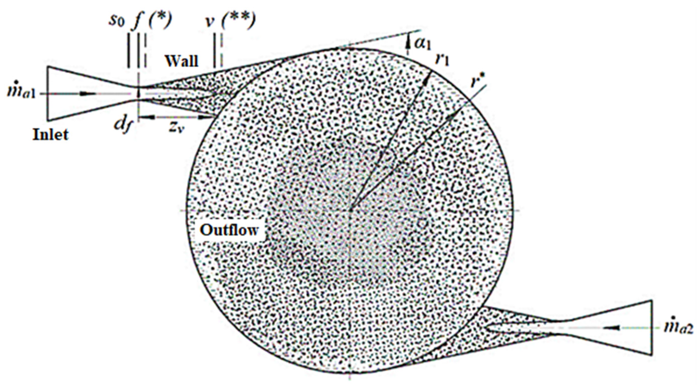
Figure 3.
The design scheme of the experimental stand: 1—vortex-type liquid–steam jet apparatus; 2—separator; 3—pump; 4—heat exchanger; 5—active flow nozzle.
Figure 3.
The design scheme of the experimental stand: 1—vortex-type liquid–steam jet apparatus; 2—separator; 3—pump; 4—heat exchanger; 5—active flow nozzle.

Figure 4.
The uneven flow in the initial cross-section I-I of the vortex camera: 1—active flow nozzles; 2—steam zones; 3—vacuum zones; 4—a vortex of the vapor–liquid mixture.
Figure 4.
The uneven flow in the initial cross-section I-I of the vortex camera: 1—active flow nozzles; 2—steam zones; 3—vacuum zones; 4—a vortex of the vapor–liquid mixture.
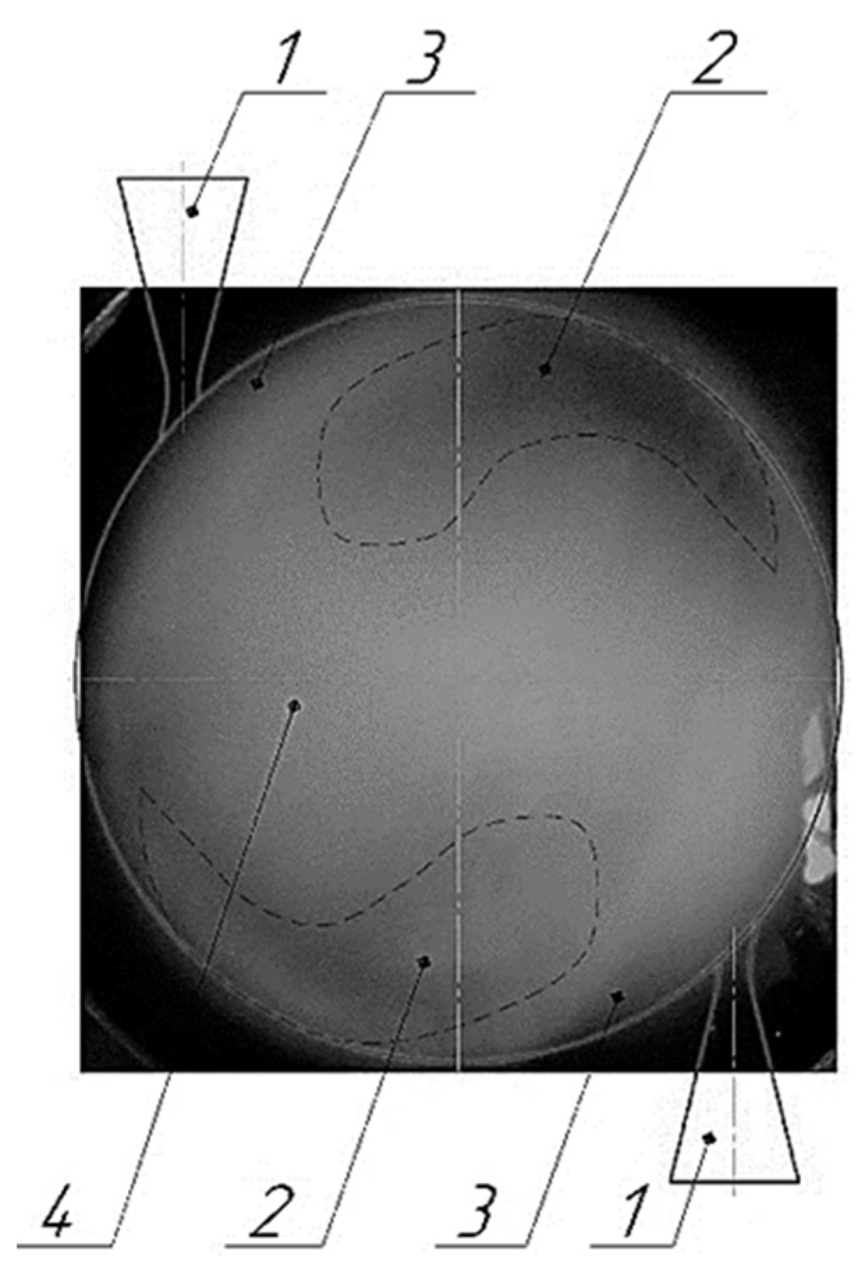
Figure 5.
Velocity contours for different values of the oblique-cut: (a) 20°; (b) 40°; (c) 60°.
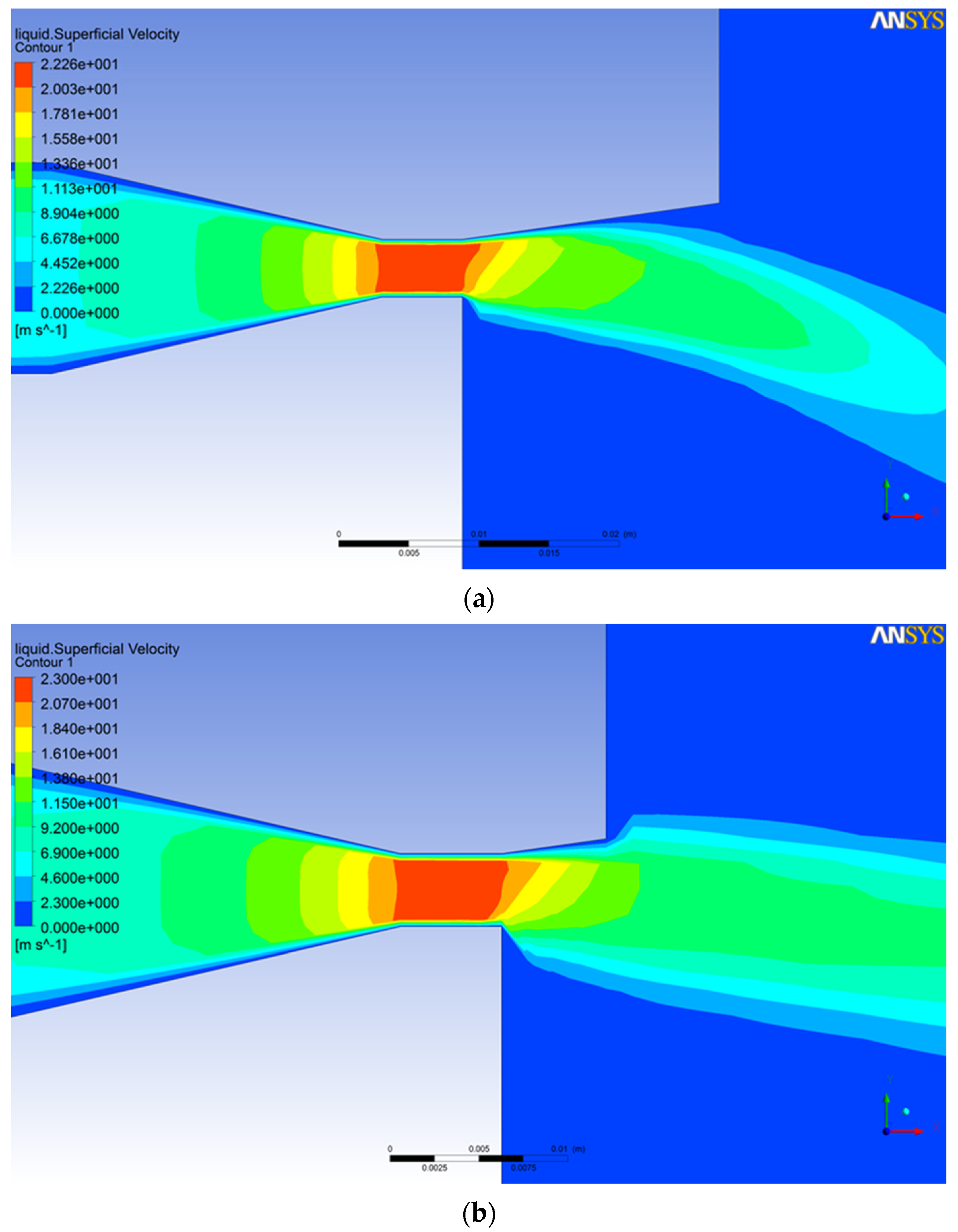

Figure 6.
Dependence of the dimensionless radius on the modified Euler number.

Figure 7.
Dependence of the relative initial underheating on the modified Euler number.
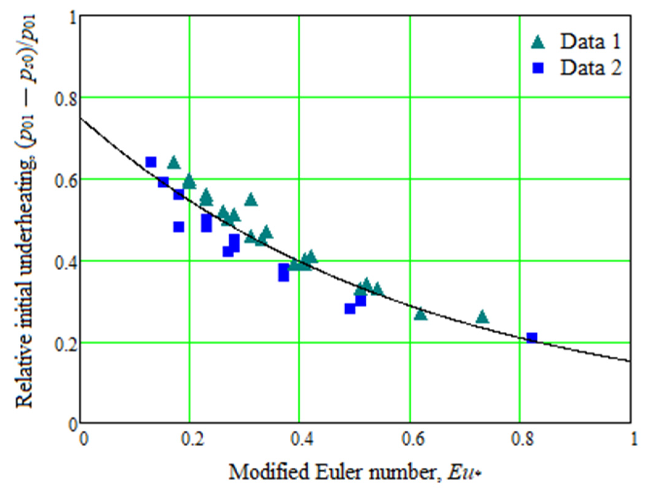
Figure 8.
Dependence of the initial bubble boiling point radius on the relative initial underheating.
Figure 8.
Dependence of the initial bubble boiling point radius on the relative initial underheating.
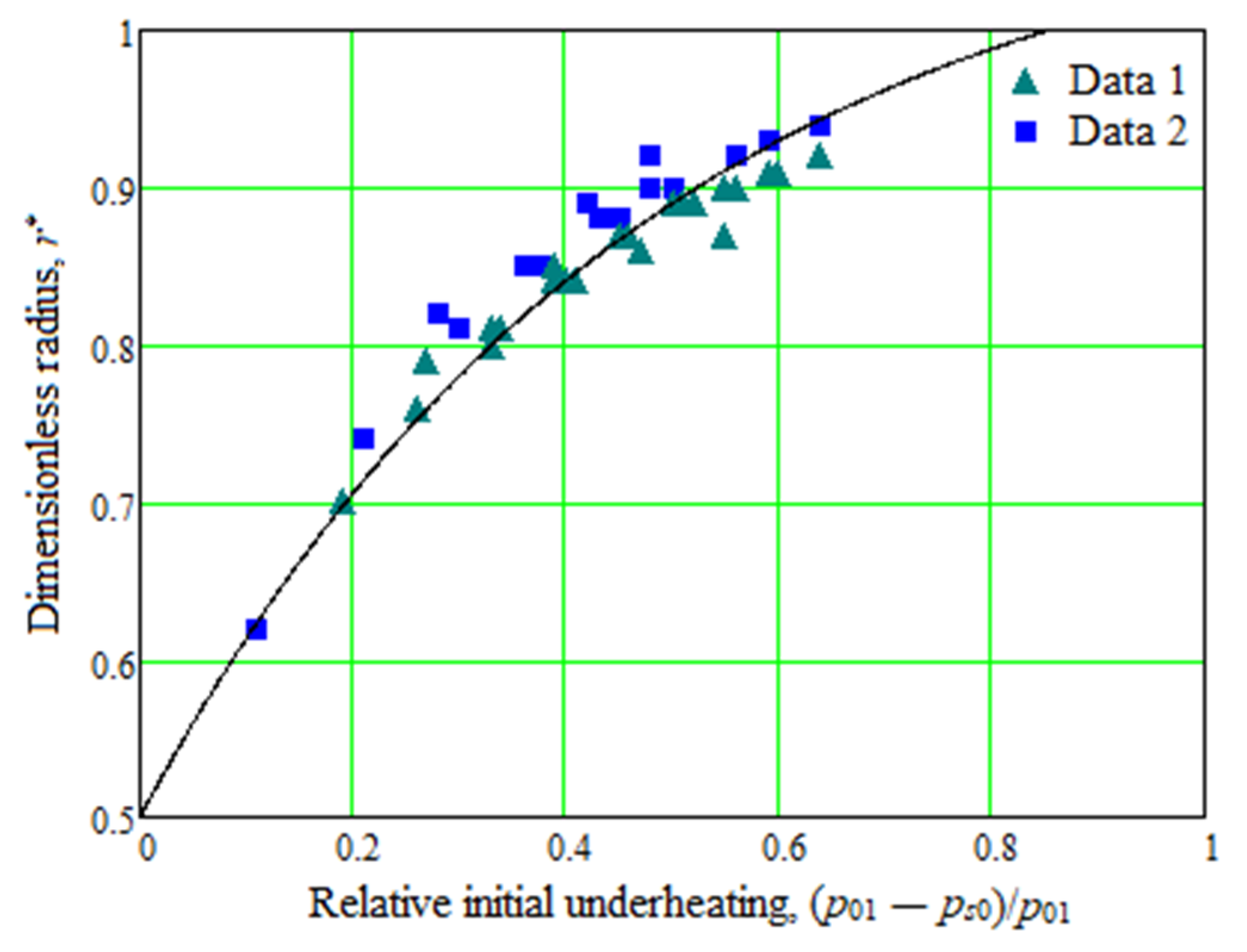
Figure 9.
A local minimum of the least square error.

Table 1.
Designs of active-flow inlet channels. Adapted with permission from Ref. [13]. 2018, Iurii Merzliakov.
Table 1.
Designs of active-flow inlet channels. Adapted with permission from Ref. [13]. 2018, Iurii Merzliakov.
| Type | The Design Scheme | Type | The Design Scheme |
|---|---|---|---|
| Spiral round | 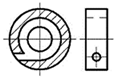 | Tangential | 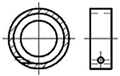 |
| Spiral rectangular |  | Dual-nozzle tangential | 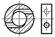 |
| Spiral tapered |  | Multi-nozzle tangential | 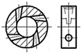 |
Table 2.
The results of the numerical calculations for the active flow nozzle.
| Critical Cross-Section Diameter, df, mm | Oblique Cut Angle, α, ° | The Taper Angle of the Nozzle, α1, ° | Flow Deflection Angle, δ, ° | Transition through the First Critical Section (*) |
|---|---|---|---|---|
| 4.1 | 20 | 16.0 | 27 | + |
| 25 | 26 | + | ||
| 30 | 24 | + | ||
| 35 | 22 | + | ||
| 40 | 20 | + | ||
| 45 | 19 | + | ||
| 50 | 15 | – | ||
| 55 | 13 | – | ||
| 60 | 12 | – |
Publisher’s Note: MDPI stays neutral with regard to jurisdictional claims in published maps and institutional affiliations. |
© 2022 by the authors. Licensee MDPI, Basel, Switzerland. This article is an open access article distributed under the terms and conditions of the Creative Commons Attribution (CC BY) license (https://creativecommons.org/licenses/by/4.0/).
Share and Cite
MDPI and ACS Style
Merzliakov, I.; Pavlenko, I.; Ochowiak, M.; Ivanov, V.; Agarwal, P. Flow Modeling in a Vortex Chamber of a Liquid–Steam Jet Apparatus. Processes 2022, 10, 984. https://doi.org/10.3390/pr10050984
AMA Style
Merzliakov I, Pavlenko I, Ochowiak M, Ivanov V, Agarwal P. Flow Modeling in a Vortex Chamber of a Liquid–Steam Jet Apparatus. Processes. 2022; 10(5):984. https://doi.org/10.3390/pr10050984
Chicago/Turabian StyleMerzliakov, Iurii, Ivan Pavlenko, Marek Ochowiak, Vitalii Ivanov, and Praveen Agarwal. 2022. "Flow Modeling in a Vortex Chamber of a Liquid–Steam Jet Apparatus" Processes 10, no. 5: 984. https://doi.org/10.3390/pr10050984
Note that from the first issue of 2016, this journal uses article numbers instead of page numbers. See further details here.