
Simulation Study on Mechanical Wear Detection of High-Power Diesel Engine Based on Thermodynamic Coupling

1
Railway Vehicle Department, Hebei Vocational College of Rail Transportation, Shijiazhuang 050022, China
2
Department of Mechanical and Electrical Engineering, Shijiazhuang University of Applied Technology, Shijiazhuang 050081, China
3
Railway Transportation Department, Hebei Vocational College of Rail Transportation, Shijiazhuang 050022, China
*
Author to whom correspondence should be addressed.
Processes 2022, 10(6), 1175; https://doi.org/10.3390/pr10061175
Submission received: 7 May 2022
/
Revised: 27 May 2022
/
Accepted: 31 May 2022
/
Published: 11 June 2022
(This article belongs to the Special Issue Enhancement of Heat Transfer and Fluid Flow)
Abstract
:The existing mechanical wear detection methods cannot accurately obtain the state characteristic data of mechanical equipment, resulting in high detection accuracy but low detection efficiency. In order to obtain more ideal results of mechanical wear detection, the mechanical wear detection technology of a high-power diesel engine based on thermodynamic coupling is designed. Through the coupling of thermodynamics, the thermal stress in the body is solved under the temperature field and corresponding boundary conditions. The state data of mechanical equipment are collected, the wavelet entropy in the state data of mechanical equipment is extracted as the feature of mechanical wear detection, and the least squares support vector machine is used to establish the mechanical wear detection model. The multi-domain unified language modelica is used to model the thermodynamic module and dynamic module of the diesel engine, respectively, to realize the joint simulation of thermodynamics and dynamics, and improve the simulation technology of mechanical wear detection of the high-power diesel engine. Through the simulation and verification test, it is found that the mechanical wear detection time is shorter, the mechanical wear detection efficiency is higher, and it has better practical application value.
1. Introduction
Mechanical equipment is an important part of many instruments [1], for example, the engine in the course of the work can be affected by other factors, can be prone to different degrees of damage, can seriously affect the life of mechanical equipment, and can make mechanical equipment no longer operate normally. Mechanical wear is an important form of mechanical damage. Mechanical wear detection is an important subject in the field of mechanical maintenance because it can be used to determine the health status of mechanical equipment [2].
With the development of computer technology and automation technology [3], mechanical wear automatic detection technology has appeared. First, the state data of mechanical equipment are collected through certain equipment, and then the corresponding mechanical wear detection features are extracted from the state data of mechanical equipment. Finally, the mechanical wear detection model is established according to the mechanical wear detection characteristics [4,5]. From the mechanical wear detection process, we can determine that the quality of mechanical equipment status data is very important. At present, the wireless sensor is mainly used to collect the data. However, due to the interference of the external environment, it is difficult to describe the characteristics of mechanical wear accurately, which has a negative impact on the subsequent mechanical wear detection. The laser sensor is a kind of equipment that uses lasers to collect data. It has low requirements on the environment and can resist external interference. It has been successfully applied in many fields [6].
The diesel engine is developing in the direction of light weight, integration, and intelligence. With the continuous improvement of thermal load and mechanical load of the diesel engine, the requirements for its safety and reliability are higher. The structure of the modern diesel engine is complex and the working conditions are poor. If the diesel engine breaks down, it will not only affect its thermal efficiency, but also cause the valve rod to break, which will make the valve head fall into the cylinder. At best, the piston and cylinder head will be jacked; at worst, the piston will be broken, the connecting rod will be bent, and even the cylinder block will be damaged. The research of diesel engine fault monitoring and diagnosis methods can not only prevent the occurrence of diesel engine faults and improve the thermal efficiency, but also have very important significance to ensure the safe operation of the diesel engine. The piston ring, cylinder liner, and main bearing are the main moving parts of the diesel engine, and their technical indexes and working conditions directly affect the power performance and reliability of the diesel engine. The piston ring of the diesel engine causes the wear of the piston ring and cylinder liner during reciprocating movement in the cylinder. When the wear amount reaches a certain fixed value, the tightness of the combustion chamber will decrease, more air leakage will occur in the compression stroke, the compression pressure will drop, and the combustion will not be complete, which will reduce the thermal efficiency of the diesel engine. The high-pressure and high-temperature gas leaking from the piston ring and cylinder wall will cause adverse consequences such as the increase in crankcase pressure and the deterioration of lubricating oil, and the insufficient combustion of the gas will reduce the power and thermal efficiency of the diesel engine, thus reducing the economy, power, and reliability of the diesel engine [7].
The main bearing of the diesel engine is a low-speed and heavy-duty bearing, which bears reciprocating inertia force of the piston connecting the rod group and gas pressure of the cylinder. As the wear degree of the diesel engine main bearing increases, the gap between the main bearing bush and crankshaft main journal becomes larger, which leads to the increase in impact force of the crankshaft on the main bearing bush and aggravation of the wear [8]. The uneven wear of the main bearing will cause the rapid wear of the cylinder liner, piston, and piston ring, resulting in loose sealing of the combustion chamber, incomplete combustion, and increase of fuel consumption rate, which will reduce the efficiency of the diesel engine.
Thermal parameter monitoring and diagnosis technology have been widely studied at home and abroad. Chen simulated the working process of the 6rlub 56 large-scale low-speed diesel engine, analyzed various thermal parameters, and carried out experimental research, which proved that it is feasible to monitor and diagnose the diesel engine by using thermal parameters [9,10,11]. In the study of Zhang et al., the working process of the model diesel engine was simulated, a variety of diesel engine faults were simulated, and the relationship between thermal parameters and fault type and fault degree was studied [12]. Taking the high-power low-speed diesel engine as the simulation object, Jannatkhah et al. simulated the normal and fault states of the diesel engine, recorded the thermal parameters of different states and carried out analysis and calculation, and extracted the diagnostic diesel engine combustion. The characteristic parameters of the oil system fault were analyzed, and the working state of the diesel engine was determined by a neural network [13]; Loganathan established the simulation model of the diesel engine thermal fault, simulated the typical thermal fault of diesel engine, analyzed the simulation results of thermal parameters and different fault types and degrees, and revealed the relationship between thermal parameters and the diesel fault state, which was used for diesel engine condition monitoring and fault. The diagnosis provided a reference basis [14].
The wear mechanism and wear form of the piston ring, cylinder liner, and main bearing were analyzed, and the corresponding wear condition monitoring method was studied. The application of this method can reduce the faults caused by excessive wear of the moving parts of the diesel engine and can improve the reliability and safety of the diesel engine, which is of great significance [15].
In order to solve the problems of low precision and low efficiency of the existing mechanical wear detection technology, a mechanical wear detection technology of a high-power diesel engine based on thermal mechanical coupling is designed. The innovation of this study is to improve the inaccurate extraction of mechanical wear feature points by traditional methods. Through the coupling of thermodynamics, the thermal stress of the object is solved under the temperature field and corresponding boundary conditions. The state data of mechanical equipment are collected, and the wavelet entropy in the state data of mechanical equipment is extracted as the feature of mechanical wear detection. Based on this, the model of mechanical wear detection is constructed. The experimental results show that the mechanical wear detection error is reduced, the mechanical wear detection accuracy is improved, and the mechanical wear detection time is shortened, which has very significant advantages [16].
2. Diesel Engine Mechanical Wear Detection Principle and Thermodynamic Parameters Monitoring
2.1. Principle of Mechanical Wear Detection
Mechanical wear detection aims to estimate the wear degree of mechanical equipment, so it is a data mining problem. Suppose that the detection feature extracted from the state data of mechanical equipment is x = {x1, x2 …,xm}, where m is the characteristic number and the wear degree of mechanical equipment is y; then, the relationship between the two can be expressed as Y = F (X) (1). The laser sensor is used to collect the mechanical equipment state data, and the wavelet entropy in the mechanical equipment state data is extracted as the mechanical wear detection feature. Finally, the least squares support vector machine is used to establish the mechanical wear detection model. The specific working principle is shown in Figure 1.
2.2. Brief Introduction of Thermal Parameter Monitoring Method
The thermal parameter monitoring method aims to judge the overall performance of the diesel engine according to the change in thermal parameters. The thermal parameters mainly include cooling water temperature, lubricating oil temperature, exhaust temperature, lubricating oil pressure, and cylinder pressure. Cylinder pressure is the most important thermal parameter. The maximum burst pressure of the diesel engine can be obtained directly by measuring cylinder pressure, and performance parameters such as indication work, compression pressure, and pressure rise rate can be obtained by calculation, to determine the diesel combustion status in the cylinder and the balance of power of each cylinder. It is difficult to measure the cylinder pressure of a small diesel engine because there is no channel for measuring cylinder pressure. The channel for measuring cylinder pressure is usually reserved for the marine diesel engine [17].
The main difficulties of thermal parameter monitoring method are: when the diesel engine has one or more fault phenomena due to multiple faults, the thermal parameters cannot accurately describe the working state of the diesel engine; the cylinder pressure thermal parameters cannot realize real-time on-line long-term monitoring, due to the limitations of sensor working conditions and price [18].
2.2.1. Thermal Analysis Theory
The basic modes of heat transfer include heat conduction, thermal convection, and thermal radiation [19]. Heat conduction, also known as heat conduction, is a way of transferring heat within a solid. The law describing heat conduction is the Fourier law:
In Formula (1), λ is the thermal conductivity of the object, also known as the thermal conductivity, W/(M·K); is the heat flux density, W/m2; gradient is the temperature gradient at a point in space.
Thermal convection is the way of heat transfer between fluid and fluid or between fluid and solid. The relation of heat convection is Newton’s cooling formula:
In Formula (2), h is the convective heat transfer coefficient, W/(m2·K).
Thermal radiation is a heat transfer mode in which the body radiates heat due to its certain temperature [20]. The law of radiation is described by the Stefan–Boltzmann law:
In Formula (3), ε is the emissivity of the object; A is the radiation surface area, m2; and σ is the Stefan–Boltzmann constant, that is, the blackbody radiation constant, whose value is 5.67 × 10⁻⁸ W/(m2·K4).
2.2.2. Mathematical Description of Heat Conduction Problem
In order to solve specific engineering problems, it is necessary not only to establish the heat conduction differential equation, but also to determine the definite solution conditions, including the corresponding time and boundary conditions. The heat balance analysis diagram of a microelement is shown in Figure 2.
Heat conduction differential equation.
Figure 2 shows the schematic diagram of any microelement in the thermal equilibrium state, where ϕx is the component of heat flow in the x-axis direction.
ϕ is the internal heat source of the object. According to Fourier’s law, the heat flux into the microelement body through the surface of x = ϕx, y = ϕy, and z = ϕz is given as:
The heat flux of the microelement can be expressed as follows: x = x + dx, y = y + dy, and z = z + dz:
The increment in thermodynamic energy of microelements is as follows: .
The heat of formation of a heat source in the microelement is as follows: .
According to the conservation of energy, the differential equation of heat conduction in a three-dimensional unsteady state can be derived:
2.2.3. Definite Solution Conditions
For steady-state heat conduction problems, only the boundary conditions are given. The three common kinds of definite solution conditions are as follows:
- (1)
- The first kind of boundary condition: for steady-state problems, the temperature value on the boundary is given, which is a function of spatial coordinates:For unsteady problems, the temperature value is also a function of time:
- (2)
- The second kind of boundary condition: the heat flux density on the boundary is given:In Equation (9), n is the normal direction of surface a.
- (3)
- The third kind of boundary condition: the temperature of the fluid outside the boundary and the convective heat transfer coefficient between the boundary and the external fluid are specified:In Equation (10), tw and are unknowns; for unsteady heat conduction, h and tf are time functions.
2.2.4. Elastic Mechanics Analysis Theory
Elastic mechanics is a subject aiming to solve the displacement, stress, and strain of an elastic deformation body under certain constraint conditions. The practical physical problems analyzed by elasticity include three kinds of basic variables, three kinds of basic governing equations, and boundary conditions [21].
- (1)
- Basic variables.
Displacement component: used to describe the position of the object after deformation, and the matrix expression is as follows:
In Formula (11), {u} is the displacement vector, also known as the displacement matrix; u, v, and w are the independent displacements in three directions in the space rectangular coordinate system.
Stress component: describes the stress state of the object, expressed in the form of a matrix:
In Formula (12), {σ} is the stress vector or stress matrix; σx, σy, and σz are three principal stresses, and τxy, τyz, and τzx are three shear stresses.
Strain component: describes the deformation degree of the object, and the matrix expression is as follows:
In Equation (13), {ε} is the strain vector, also known as the strain matrix, εx, εy, and εZ are three normal stresses, and , and are three shear strains.
- (2)
- Basic governing equations. Under the external action, the elastic deformation will produce displacement, stress, and strain, which meet the corresponding control equations. The distribution is called the geometric equation of deformation, the physical equation of material, and the balance equation of force. The relationship between the strain component and displacement component is as follows:
The physical equation or constitutive equation of the material is the stress–strain equation. For isotropic, homogeneous, continuous, and perfectly elastic objects, the equation satisfies the generalized Hooke’s law:
In Formula (15), E is the elastic modulus or Young’s modulus, Pa; G is the shear modulus of elasticity, Pa; μ is Poisson’s ratio, and there is a relationship .
The force balance equation describes the stress state of the deformed body:
In Equation (16):
In Equation (18), {b} represents the three components of volume force in rectangular coordinate system.
- (3)
- The condition of definite solution. It includes the displacement boundary condition and force boundary condition. Expressions of displacement boundary conditions:
The boundary condition of the force is expressed as follows:
In Equation (20), represents the three components of the boundary distributed force vector in the space rectangular coordinate system, and [n] is the direction cosine.
2.2.5. Thermoelastic Analysis Theory
The deformation body will deform due to the effect of a temperature field, which is called thermal deformation:
In Formula (21), ε t is the thermal strain and β is the coefficient of linear expansion.
Total strain due to displacement in the body:
In Equation (22), ε σ is the strain caused by stress.
The generalized Hooke’s law with temperature strain is considered:
As long as the temperature field and the corresponding boundary conditions are known, the thermal stress in the body can be solved.
3. Simulation of Diesel Engine Mechanical Wear Detection Based on Thermodynamic Coupling
3.1. Mechanical Wear Detection Algorithm
For mechanical wear testing, the sample set is: {(xi, yi)}, i = 1, 2, n, xi Rn, yi R, where xi and yi represent the characteristics of mechanical wear detection and the degree of mechanical wear, respectively:
Based on machine learning theory, the equivalent form of Equation (24) can be obtained as follows:
In Equation (25), γ is the normalized parameter.
Lagrange multiplier α I is used to establish the Lagrange function:
According to the duality theory and optimization conditions, , , , and , the relaxation factor is introduced:
The kernel function is used to replace the inner product formula, that is, , and the mechanical wear detection model is obtained as follows:
The kernel function adopts the RBF function and is its width parameter:
The model of mechanical wear detection is changed into:
3.2. Coupled Thermodynamic Modeling
When using simulation software to simulate the dynamics of moving parts of the diesel engine, it is necessary to add an external load, which is usually the gas pressure in the cylinder. The main way to obtain the dynamic simulation is to use the thermodynamic calculation software of the diesel engine to simulate the cylinder process, obtain the change data of the gas pressure in the cylinder with the crankshaft angle, and then import it into the software for thermodynamic simulation. However, the diesel engine is a kind of complex motion machinery with thermodynamics and dynamics at the same time [22,23].
In this paper, multidomain unified language modelica is used to model the thermodynamic module and dynamic module of the diesel engine. In the process of modeling, the thermodynamic module and the dynamic module transfer data through the interface: the thermodynamic module defines the wall temperature of the combustion chamber of the diesel engine as the boundary condition by inputting the structural dimension parameters of the diesel engine, sets the initial conditions, and calculates the change in the gas pressure in the cylinder with the crankshaft angle by using the differential equation in the cylinder. The pressure is transmitted to the dynamics module through the interface in real time [24,25]. The dynamics module can calculate the kinematics and dynamics characteristics of the crank linkage mechanism according to the gas pressure in the cylinder, and can calculate the output torque of the diesel engine. Before the output torque and the load torque are balanced, the diesel engine speed continues rising. When the load torque and output torque are equal, the diesel engine speed is stable. During this period, the diesel engine speed is transmitted to the cylinder through the interface in real time. The real-time speed can be brought into the calculation to obtain the changes in piston displacement, speed, reciprocating inertia force, and other characteristic parameters from the start to the stable time. The joint simulation of thermodynamics and dynamics is realized, and the performance simulation technology of the diesel engine is improved [26,27].
4. Case Analysis of Mechanical Wear Detection
4.1. Test Platform and Mechanical Wear Data
In order to verify the performance of the mechanical wear detection technology for the high-power diesel engine based on thermal dynamic coupling, the traditional technology was selected to carry out comparative experiments in the same experimental environment. The evaluation platform was an Intel i5-8 500 CPU, Kingston 8 GDD R4 2666 memory, Kingston 128 g M. 2 SSD hard disk, and Windows 7 operating system. The degree of mechanical wear was divided into four grades, and their description and sample number are shown in Table 1.
4.2. Results and Analysis
The algorithm in this paper was compared with the algorithm in Hoang et al. [5] and Amaaa et al. [6] to learn the training samples of mechanical wear detection, establish the mechanical wear detection model, test the mechanical wear test samples, and count their mechanical wear detection accuracy rate (%), false detection rate (%), missing detection rate (%), and detection time (MS), as shown in Figure 3, Figure 4, Figure 5 and Figure 6.
According to the experimental test results obtained in Figure 3, when using the research method to detect mechanical wear, the detection accuracy of no wear, light wear, medium wear, and serious wear could reach more than 96%, and the accuracy test results had ideal stability. The application effect of the method proposed in Hoang et al. [5] and Amaaa et al. [6] was not very ideal. For different degrees of mechanical wear, the detection accuracy was always lower than 93%, and the lowest accuracy was 89%. In contrast, the application effect of the research method was better than that of the reference method.
Figure 4 and Figure 5 show the false detection rate and missed detection rate of mechanical wear detection using the experimental algorithm and the algorithm of Hoang et al. [5] and Amaaa et al. [6] respectively.
It can be seen from the figure that the error detection rate and missed detection rate of mechanical wear detection based on the algorithm of Hoang et al. [5] and Amaaa et al. [6] were high, while the error detection rate and missed detection rate of mechanical wear detection using this experimental algorithm were low, and ideal mechanical wear detection results could be obtained. This is because the experimental algorithm could better analyze the relationship between mechanical wear detection characteristics and mechanical wear degree, and the reliability of mechanical wear detection results was higher.
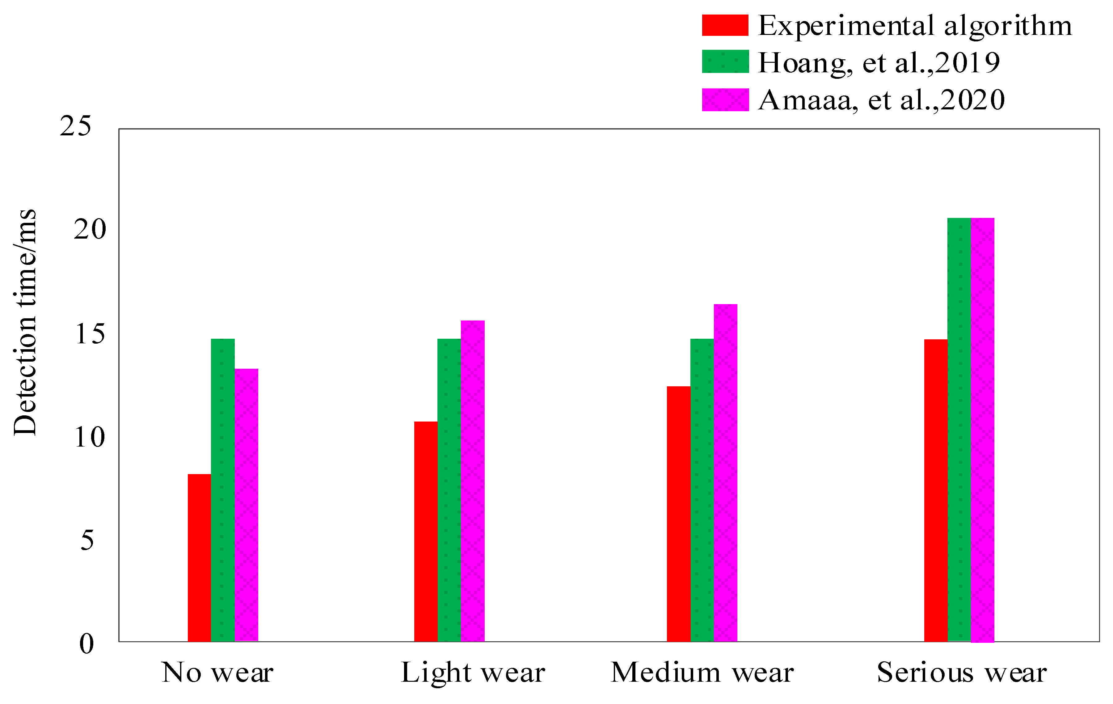
Figure 6 shows the time consumption of mechanical wear detection by comparing the experimental algorithm with Hoang et al. [5] and Amaaa et al. [6]. As can be seen from Figure 6, the mechanical wear detection time of the experimental algorithm was lower. When serious wear occurred, the detection time still remained below 15 ms. When the reference methods of Hoang et al. [5] and Amaaa et al. [6] were used to detect different degrees of mechanical wear, its time consumption was always higher than 15 ms, and the maximum time consumption was up to 20 ms. It can be seen from Figure 6 that the mechanical wear detection time of the experimental algorithm was significantly less than that of the comparative technology, which reduced the computational time complexity of mechanical wear detection and improved the efficiency of mechanical wear detection significantly.
5. Conclusions
Mechanical wear is affected by many factors and has very complex change characteristics. It is difficult for the current mechanical wear detection technology to carry out high-precision detection of mechanical wear, and the mechanical wear detection efficiency is low. In order to obtain more ideal mechanical wear detection results, a mechanical wear detection technology method based on a laser sensor is designed, and the simulation verification test is carried out. When using the research method to detect mechanical wear, the detection accuracy of no wear, light wear, medium wear, and serious wear can reach more than 96%, and the accuracy test results have ideal stability. The false detection rate and missed detection rate are always lower than 6% when the experimental algorithm is applied. Moreover, the mechanical wear detection time of the experimental algorithm is lower. When serious wear occurs, the detection time still remains below 15 ms. When the reference method is used to detect different degrees of mechanical wear, its time consumption is always higher than 15 ms, and the maximum time consumption is up to 20 ms.
According to the data obtained from the above experimental tests, it can be seen that: the least squares support vector machine (LSSVM) is introduced to establish the mechanical wear detection model, which can fit the relationship between the mechanical wear characteristics and the mechanical wear degree, and effectively reduce the error of the mechanical wear degree detection. Compared with other current mechanical wear detection methods, this method has a shorter mechanical wear detection time, improves the efficiency of mechanical wear detection, and has higher practical application value.
Author Contributions
Conceptualization, J.L. (Jianwei Liang); data curation, J.L. (Jingli Li); formal analysis, B.M.; writing—original draft, J.L. (Jingli Li); writing—review and editing, Y.Z. All authors have read and agreed to the published version of the manuscript.
Funding
This research received no external funding.
Institutional Review Board Statement
Not applicable.
Informed Consent Statement
Not applicable.
Data Availability Statement
The data used to support the findings of this study are available from the corresponding author upon request.
Conflicts of Interest
The authors declare no conflict of interests.
References
- Temizer, L.; Eskici, B. Investigation on the combustion characteristics and lubrication of biodiesel and diesel fuel used in a diesel engine. Fuel 2020, 278, 118363. [Google Scholar] [CrossRef]
- Zehni, A.; Saray, R.K.; Neshat, E. A detailed study of the effects of biodiesel addition and exhaust gas recirculation on diesel engine pcci combustion, performance and emission characteristics by kiva-chemkin coupling. J. Eng. Gas Turbines Power 2018, 140, 062801. [Google Scholar] [CrossRef]
- Yang, C.; Liu, R.; Jiao, Y.; Zhang, Z.; Zhou, G.; Ding, H.; Lu, C. Study on thermodynamic matching optimization of variable flow cooling system of diesel engine at high altitudes. Energy Sources Part A Recovery Util. Environ. Eff. 2020, 3, 1–19. [Google Scholar] [CrossRef]
- Kumar, K.M.; Munjal, M.L. Direct estimation and experimental validation of the acoustic source characteristics of two-cylinder naturally aspirated diesel engine exhaust system. Appl. Acoust. 2018, 135, 70–84. [Google Scholar] [CrossRef]
- Hoang, A.T.; Pham, V.V. A study of emission characteristic, deposits, and lubrication oil degradation of a diesel engine running on preheated vegetable oil and diesel oil. Energy Sources Part A Recovery Util. Environ. Eff. 2019, 41, 611–625. [Google Scholar] [CrossRef]
- Attia, A.M.; Nour, M.; El-Seesy, A.I.; Nada, S.A. The effect of castor oil methyl ester blending ratio on the environmental and the combustion characteristics of diesel engine under standard testing conditions. Sustain. Energy Technol. Assess. 2020, 42, 100843. [Google Scholar] [CrossRef]
- Hoang, A.T.; Le, V.V.; Pham, V.V.; Tham, B.C. An investigation of deposit formation in the injector, spray characteristics, and performance of a diesel engine fueled with preheated vegetable oil and diesel fuel. Energy Sources Part A Recovery Util. Environ. Eff. 2019, 41, 2882–2894. [Google Scholar] [CrossRef]
- Bagi, S.; Kamp, C.J.; Sharma, V.; Aswath, P.B. Multiscale characterization of exhaust and crankcase soot extracted from heavy-duty diesel engine and implications for DPF ash. Fuel 2020, 282, 118878. [Google Scholar] [CrossRef]
- Chen, Z.; Li, J.; Liao, J.; Shi, F. Stress and fatigue analysis of engine pistons using thermo-mechanical model. J. Mech. Sci. Technol. 2019, 33, 4199–4207. [Google Scholar] [CrossRef]
- Liu, J.; Dumitrescu, C.E. Improved thermodynamic model for lean natural gas spark ignition in a diesel engine using a triple wiebe function. J. Energy Resour. Technol. 2020, 142, 062303. [Google Scholar] [CrossRef]
- Pan, M.; Qian, W.; Huang, R.; Tong, C.; Huang, H.; Xu, L.; Hao, B. Effects of dimethyl carbonate and 2-ethylhexyl nitrate on energy distribution, combustion and emissions in a diesel engine under different load conditions. Energy Convers. Manag. 2019, 199, 111985. [Google Scholar] [CrossRef]
- Zhang, Y.; Zhan, L.; He, Z.; Jia, M.; Leng, X.; Zhong, W.; Qian, Y.; Lu, X. An investigation on gasoline compression ignition (GCI) combustion in a heavy-duty diesel engine using gasoline/hydrogenated catalytic biodiesel blends. Appl. Therm. Eng. 2019, 160, 113952. [Google Scholar] [CrossRef]
- Jannatkhah, J.; Najafi, B.; Ghaebi, H. Thermodynamic analysis of a four-stroke compression ignition engine fueled by corn biodiesel blends and pure diesel. Energy Sources Part A Recovery Util. Environ. Eff. 2019, 1–20. [Google Scholar] [CrossRef]
- Loganathan, S.; Martin, M.L.J.; Nagalingam, B.; Prabhu, L. Heat release rate and performance simulation of dme fuelled diesel engine using oxygenate correction factor and load correction factor in double wiebe function. Energy 2018, 150, 77–91. [Google Scholar] [CrossRef]
- Ding, N. Vibration analysis of offshore oil and gas platform mechanical equipment. J. Coast. Res. 2020, 106, 633–637. [Google Scholar] [CrossRef]
- Heda, Z. Fault diagnosis and life prediction of mechanical equipment based on artificial intelligence. J. Intell. Fuzzy Syst. 2019, 37, 3535–3544. [Google Scholar] [CrossRef]
- Li, X.; Feng, Y.; Liu, B.; Yi, D.; Yang, X.; Zhang, W.; Chen, G.; Liu, Y.; Bai, P. Influence of NbC particles on microstructure and mechanical properties of AlCoCrFeNi high-entropy alloy coatings prepared by laser cladding. J. Alloy. Compd. 2019, 788, 485–494. [Google Scholar] [CrossRef]
- Huo, J.; Lin, D.; Qi, W. Intelligent fault diagnosis method of mechanical equipment based on fuzzy pattern recognition. J. Intell. Fuzzy Syst. 2020, 38, 3657–3664. [Google Scholar] [CrossRef]
- Wang, L.; Chen, A.H.; Huang, Y.N. Simulation of NOX emission intensity control of diesel engine based on miller cycle. Comput. Simul. 2020, 37, 105–108. [Google Scholar]
- Qian, Z.; Huang, H. Coupling fatigue cohesive zone and magnetomechanical model for crack detection in coating interface. NDT E Int. 2019, 105, 25–34. [Google Scholar] [CrossRef]
- Zhao, G.X.; Wu, S.L.; Chen, H.C.; Zhao, W.J. Simulation research on fouling diagnosis of conducting heat tube in heat. Exch. Computer Simul. 2019, 36, 427–431. [Google Scholar]
- Jiao, Y.; Zheng, Q. Urea injection and uniformity of ammonia distribution in SCR system of diesel engine. Appl. Math. Nonlinear Sci. 2020, 5, 129–142. [Google Scholar] [CrossRef]
- Li, B.; Yang, H. Design of active vibration reduction system for intelligent ship mechanical equipment. J. Coast. Res. 2020, 115, 235–237. [Google Scholar] [CrossRef]
- Qin, C.; Jin, Y.; Tao, J.; Xiao, D.; Yu, H.; Liu, C.; Shi, G.; Lei, J.; Liu, C. DTCNNMI: A deep twin convolutional neural networks with multi-domain inputs for strongly noisy diesel engine misfire detection. J. Int. Meas. Confed. 2021, 180, 109548. [Google Scholar] [CrossRef]
- Zheng, J.; Zhang, C.; Li, A. Experimental investigation on the mechanical properties of curved metallic plate dampers. Appl. Sci. 2019, 10, 269. [Google Scholar] [CrossRef] [Green Version]
- Pham, V.V. Research on the application of diesel-RK in the calculation and evaluation of technical and economic criteria of marine diesel engines using the unified ULSD and biodiesel blended fuel. J. Mech. Eng. Res. Dev. 2019, 42, 87–97. [Google Scholar] [CrossRef]
- Wang, Y.; Zhang, G.; Shi, Z.; Wang, Q.; Su, J.; Qiao, H. Finite-time active disturbance rejection control for marine diesel engine. Appl. Math. Nonlinear 2020, 5, 35–46. [Google Scholar] [CrossRef]
Figure 1.
Working principle of mechanical wear detection model.
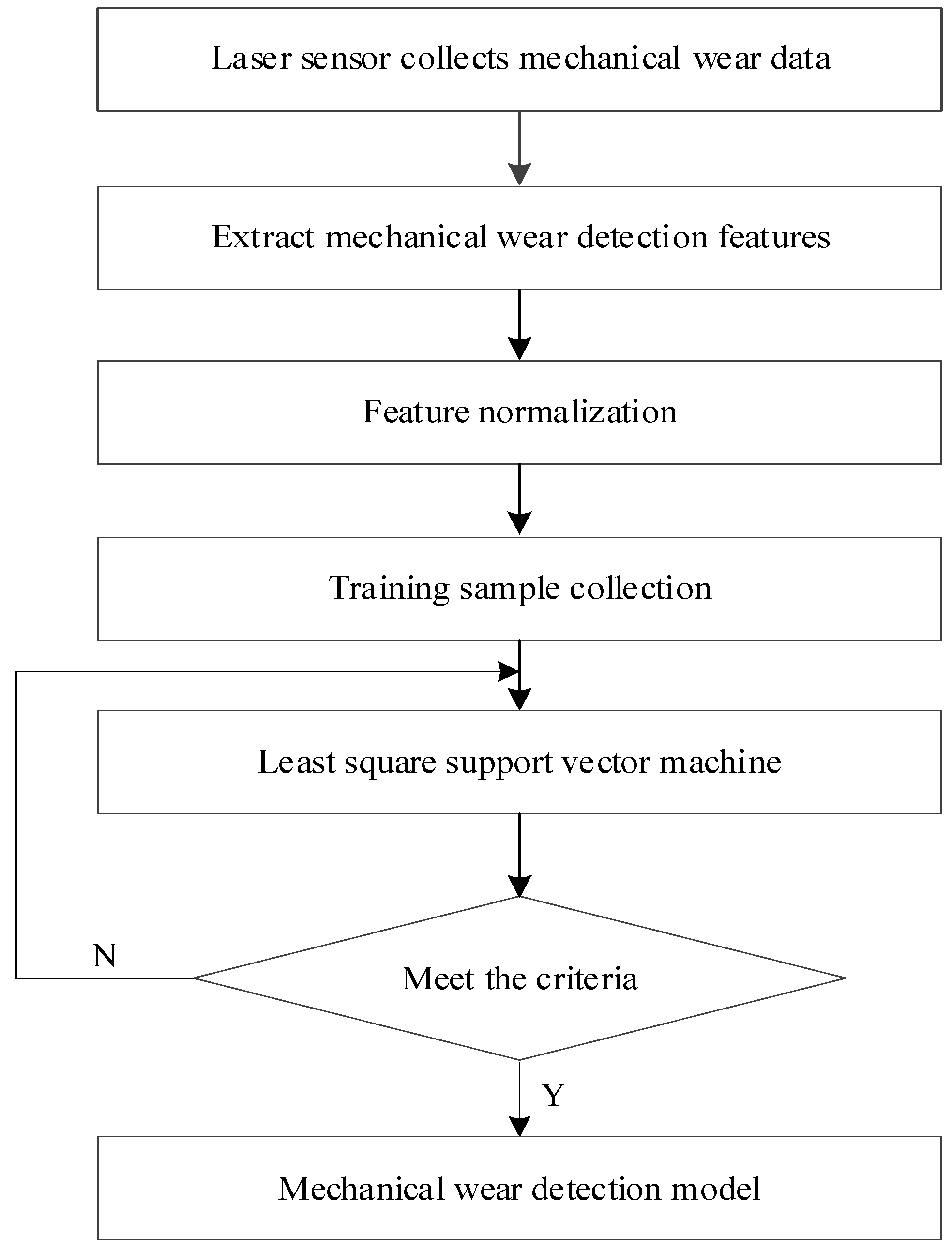
Figure 2.
Schematic diagram of thermal balance analysis of microelement.
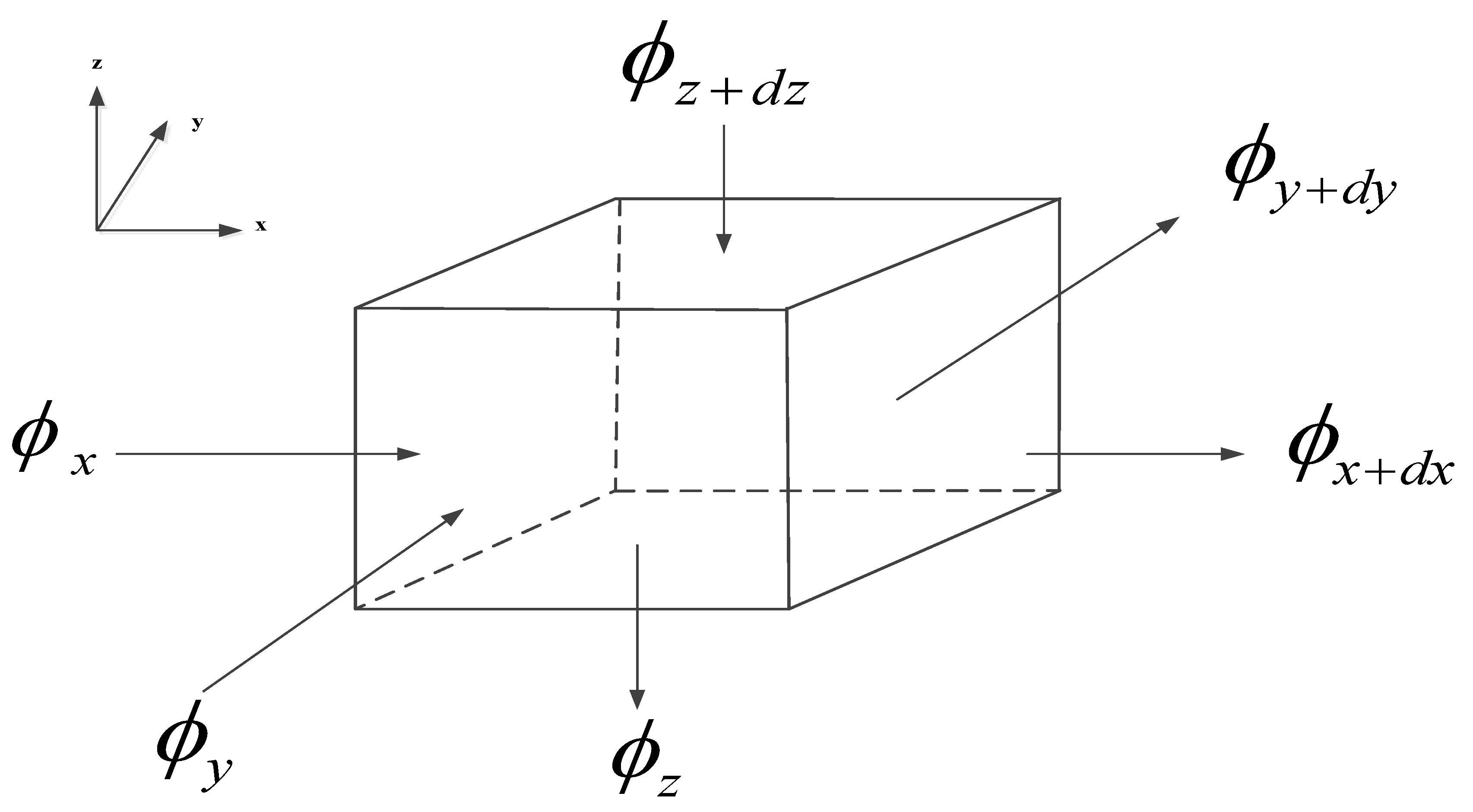
Figure 3.
Accuracy of mechanical wear detection.
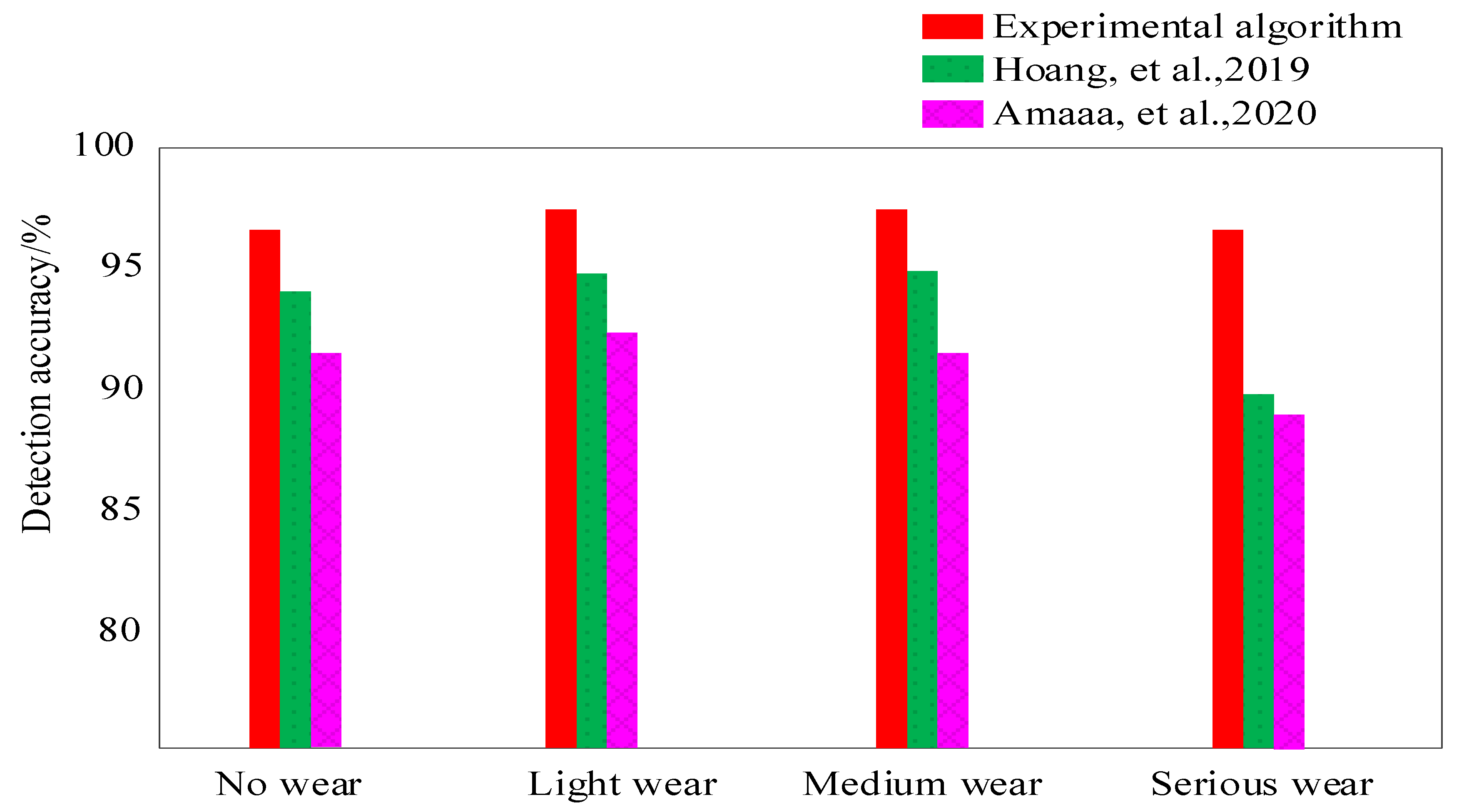
Figure 4.
False detection rate of mechanical wear.

Figure 5.
Missing rate of mechanical wear.

Figure 6.
Detection time of mechanical wear.

Table 1.
Data of mechanical wear test.
| Numbering | Degree Of Mechanical Wear | Number Of Samples |
|---|---|---|
| 1 | No wear | 50 |
| 2 | Mild wear | 50 |
| 3 | Medium wear | 30 |
| 4 | Severe wear | 10 |
Publisher’s Note: MDPI stays neutral with regard to jurisdictional claims in published maps and institutional affiliations. |
© 2022 by the authors. Licensee MDPI, Basel, Switzerland. This article is an open access article distributed under the terms and conditions of the Creative Commons Attribution (CC BY) license (https://creativecommons.org/licenses/by/4.0/).
Share and Cite
MDPI and ACS Style
Li, J.; Ma, B.; Liang, J.; Zhang, Y. Simulation Study on Mechanical Wear Detection of High-Power Diesel Engine Based on Thermodynamic Coupling. Processes 2022, 10, 1175. https://doi.org/10.3390/pr10061175
AMA Style
Li J, Ma B, Liang J, Zhang Y. Simulation Study on Mechanical Wear Detection of High-Power Diesel Engine Based on Thermodynamic Coupling. Processes. 2022; 10(6):1175. https://doi.org/10.3390/pr10061175
Chicago/Turabian StyleLi, Jingli, Baoqiu Ma, Jianwei Liang, and Yu Zhang. 2022. "Simulation Study on Mechanical Wear Detection of High-Power Diesel Engine Based on Thermodynamic Coupling" Processes 10, no. 6: 1175. https://doi.org/10.3390/pr10061175
Note that from the first issue of 2016, this journal uses article numbers instead of page numbers. See further details here.