
Fuzzy Control Strategies Development for a 3-DoF Robotic Manipulator in Trajectory Tracking


Electrical Engineering Department, Faculty of Engineering, University of Santiago of Chile (USACH), Av. Víctor Jara 3519, Estación Central, Santiago 9170124, Chile
*
Author to whom correspondence should be addressed.
Processes 2023, 11(12), 3267; https://doi.org/10.3390/pr11123267
Submission received: 26 October 2023
/
Revised: 15 November 2023
/
Accepted: 19 November 2023
/
Published: 22 November 2023
(This article belongs to the Special Issue Advances in the Control of Complex Dynamic Systems)
Abstract
:This research delves into the development and evaluation of two distinct controllers for a 3-DoF robotic arm in the context of Industry 4.0. Two primary control strategies are presented in the study. The first is a Fuzzy Logic Controller that utilizes joint position error and its derivative as inputs, employing a set of 9 control knowledge rules. The second is an Adaptive Neuro-Fuzzy Inference System (ANFIS) Controller, trained to learn the inverse dynamic model of the robot through a structured dataset. The research emphasizes the importance of accurate parameter tuning and data acquisition to achieve optimal control system performance. Extensive experimentation was conducted to evaluate the controllers’ performance in trajectory tracking and their response against external disturbances, such as load variations. The controllers exhibited remarkable precision and proficiency in tracking reference trajectories, with minimal deviations, overshoots, or oscillations. A quantitative analysis using performance indices such as root mean square error (RMSE) and the integral of the absolute value of the time-weighted error (ITAE) further confirmed the controllers’ effectiveness. Notably, the ANFIS Controller consistently outperformed the Fuzzy Logic Controller, demonstrating superior precision in trajectory tracking. The study underscored the importance of selecting the right control method and obtaining high-quality training data. Challenges in parameter tuning for Fuzzy Logic Controllers and potential time constraints in training ANFIS were discussed. The findings have significant implications for advancing robotic control systems, particularly in the era of Industry 4.0.
1. Introduction
In the era of Industry 4.0, robotic manipulation technologies have revolutionized industrial manufacturing processes, transforming robots into flexible, autonomous, and intelligent entities [1,2]. Robotic arms, known for their versatility in tasks such as welding, pick-and-place, assembly, and precision operations, play a pivotal role [3,4].
However, developing effective controllers for these dynamic, nonlinear, and multivariable robotic arms poses significant challenges, especially as demands for higher accuracy, performance, speed, reliability, autonomy, and adaptability increase [5,6].
Among the different types of controllers, the Fuzzy Logic Controller has gained popularity due to its linguistic structure and its robustness in controlling nonlinear systems. By implementing knowledge-based control rules, it enables addressing the difficulty or impossibility of modeling some systems through mathematical equations [7].
This technique is categorized under the realm of expert systems, specifically oriented towards numerical processing. In these systems, fuzzy logic is employed to define inference rules and membership functions, facilitating reasoning about data and decision-making. Expert knowledge is encapsulated in the form of IF-THEN rules, which proves to be better adapted to the analyzed problem [8].
In [9], the use of a fuzzy controller for the control of a 2-DoF manipulator is proposed. The authors employ fuzzy sets to design a trajectory planning scheme using a trapezoidal fuzzy PID (Proportional, Integral, Derivative), which allows them to effectively control the symmetric motion of the manipulator. The design of two type-I and type-II fuzzy controllers is presented in [10] for the position and force control of a robot in an object manipulation task. This robot is composed of an angular gripper with two fingers attached to a robotic arm mounted on a mobile robot. A comparison of the performance of both controllers and a PID was established, with the type-I fuzzy controller obtaining the best results.
A novel iterative feedback method for PID controller tuning using fuzzy logic is proposed in [11]. The proposed method uses the desired overshoot characteristics and the settling time of the plant to calculate the error. Then, the error value is sent to the fuzzy logic based tuning system to calculate the PID gains. In [12], a fuzzy PID controller is also introduced. In this work, the controller is tuned using the Cuckoo Search (CS) algorithm to control a highly nonlinear 3-degree-of-freedom robotic manipulator for trajectory tracking.
The work presented in [13] introduces a control method based on fuzzy logic and fractional-order (FO) operators. It employs an extended PID error manifold and a Takagi-Sugeno inference system based on the extended PID error and its FO integral. A fuzzy linear quadratic regulator (FLQR) controller is presented in [14], where an optimal control approach, as in the linear quadratic regulator (LQR), is combined with a fuzzy control approach.
In [15], the authors address the problem of actuator saturation in controller design. For this purpose, they present a design method of fuzzy controllers subject to actuator saturation for nonlinear systems with uncertain parameters. In [16], a fuzzy proportional-derivative (PD) controller is proposed to overcome the uncertainties of a robotic manipulator in real-time.
Recent advancements in fuzzy control have been directed towards simplifying structures and reducing computational loads associated with numerous logic rules. In the realm of adaptive control for nonlinear systems, the focus has shifted towards adaptive mechanisms with minimal learning parameters, alleviating computational challenges linked to the increasing number of adaptive laws. An event-based adaptive tracking control scheme, introduced in [17], aims to enhance computational efficiency while ensuring robust tracking performance. Additionally, a low-computation adaptive fuzzy control strategy, coupled with constraint-handling techniques, has been presented in [18] for precise trajectory tracking and signal boundedness in systems characterized by unknown nonlinear functions and unmatched disturbances.
Moreover, adaptive fuzzy finite-time control has attracted attention. Research in this domain has explored applications in pure feedback switched nonlinear systems, leveraging dynamic surface control and backstepping techniques to enhance robustness and anti-disturbance performance [19]. This approach has also found application in [20], emphasizing robustness, chattering avoidance, fault tolerance, and saturation elimination.
One of the drawbacks of fuzzy controllers is the lack of a systematic methodology for their design. These systems are not experts by themselves, as they need an adjustment of their parameters [21]. In most cases, there is not enough knowledge about the behavior of the system. For this reason, the trial-and-error method is usually used in the design to obtain the best performance, which sometimes requires a lot of time.
To overcome this limitation, the use of neural network learning techniques has been proposed as a way to automate this process, reducing time significantly and increasing performance. The fusion of Artificial Neural Networks (ANN) and Fuzzy Inference Systems (FIS) has resulted in the Adaptive Neuro-Fuzzy Inference System (ANFIS) techniques as a powerful method in the resolution of control tasks.
Based on the input and output data of the systems, ANN learns the behavior of the system, applies the corresponding rules, and assigns the correct values of membership functions using error minimization algorithms [22].
In [23], ANFIS is employed to perform an input–output mapping of the inverse dynamic model of a 5-DoF manipulator robot (Intelbot). The ANFIS system is trained using the robot’s joint coordinates and a payload index to allow the robot to work with varying loads. A similar approach is implemented in [24], where an ANFIS network is trained to model the inverse dynamics of the 6-DoF Stanford Robotic Arm. In [25], ANFIS has been used for cooperative control of two 3-DoF manipulators that grasp a common object under the constraint of no-slipping.
A controller designed using a computed torque controller (PD type) based on an ANFIS system is presented in [26]. In the paper, the authors demonstrate that this approach allows the achievement of high accuracy in trajectory tracking and satisfactory stabilization, improving the performance obtained with the traditional computed torque method. The ANFIS network is trained to automatically adjust the gain parameters and of the controller to compensate for the inaccuracies of the dynamic model.
In [27], an adaptive fuzzy computed pair control system is proposed. In this case the ANFIS is used to compensate the deviations caused by the presence of structured uncertainty and unstructured uncertainty.
The use of ANFIS for controlling a 4-DoF hydraulic manipulator is proposed in [28] to increase the accuracy of trajectory tracking. Similar to the other research cited here, the function of ANFIS consists of the adaptive regulation of the parameters of a PID controller using autonomous learning and its fuzzy reasoning capability.
The focus of this study is on the development of intelligent controllers for a 3-DoF robotic arm, specifically fuzzy and ANFIS controllers, to address the intricate control requirements of robotic arms in Industry 4.0 scenarios. The main objective is to contribute to the development of automatic control systems by analyzing the behavior of both controllers and evaluating their performance in trajectory tracking using performance indices.
The major contributions of this work are described below:
- A detailed and comparative evaluation is presented for two intelligent control strategies: the Fuzzy Logic Controller and the Adaptive Neuro-Fuzzy Inference System (ANFIS), specifically applied to a 3-DoF robotic arm. The study emphasizes the precision and overall performance of both controllers, as demonstrated by comprehensive assessments, particularly in trajectory tracking;
- A thorough comparison with recently published controllers not only establishes that the proposed controllers demonstrate robust performance but also demonstrates their superiority in a competitive manner. This comprehensive analysis extends beyond trajectory tracking, incorporating an examination of their responsiveness to external disturbances, providing valuable insights into the controllers’ resilience and practical applicability;
- The efficiency achieved by the ANFIS controller in precise trajectory tracking and effective regulation, even in the presence of load variations in the robotic arm system, is demonstrated. This robust and adaptable performance of ANFIS holds significant implications across various industrial scenarios where adaptability to load fluctuations is crucial for operational success;
- This study enriches the field of industrial robotics by providing a quantitative analysis supported by performance indices. This methodology simplifies the objective comparison of the controllers, enabling a precise and measurable understanding of their effectiveness in practical scenarios. This approach significantly contributes to the development of evaluative standards, thereby consolidating the relevance and applicability of the controllers in advanced industrial environments.
This paper is structured as follows: Section 2 details the kinematic and dynamic models of the plant used to test the controllers. Section 3 address the theoretical foundations and design parameters for the development of the fuzzy controller and ANFIS. Section 4 describes the simulation environment used to test the controllers and discusses the results. The conclusions are presented in Section 5, as well as potential future work.
2. Description of the System under Study
Modeling is the first step in the design of controllers. Knowing the mathematical equations or physical characteristics of the system to be controlled is critical. The kinematic model and the dynamic model are the base elements for the development of controllers for robotic arms. Kinematics refers to the science that explains motion, i.e., position, velocity, and acceleration, as well as their derivatives, without taking into account the forces that cause such motion. Dynamics is the science that establishes the relationship between motion and force [29].
2.1. Kinematic Robot Model
Direct kinematics describes the relationship of spatial coordinates as a function of joint coordinates [30]. The Denavit–Hartenberg (D-H) method is used to obtain the direct kinematic model. The reference systems of the links used in the modeling are shown in Figure 1. The D-H parameters are established in Table 1, with , , and .
Applying the transformations described by Equation (1), the homogeneous transformation matrix of the system is obtained in Expression (2), from which the relationships describing the direct kinematic model are derived. Expression (3) represents the position vector, and Equation (4) represents the rotation matrix describing the orientation of the end effector with respect to the base, where , , , and .
where
Inverse kinematics problem consists of determining the joint variables corresponding to a given position and orientation of the end effector (EF) [31]. The procedure is based on establishing sufficient relationships between the two coordinate systems, and these equations depend on the geometry and physical dimensions of the robot [30].
For robots with few degrees of freedom, geometric methods can be employed to solve the inverse kinematic problem. Trigonometric and geometric relations on the robot elements are utilized for this purpose [30].
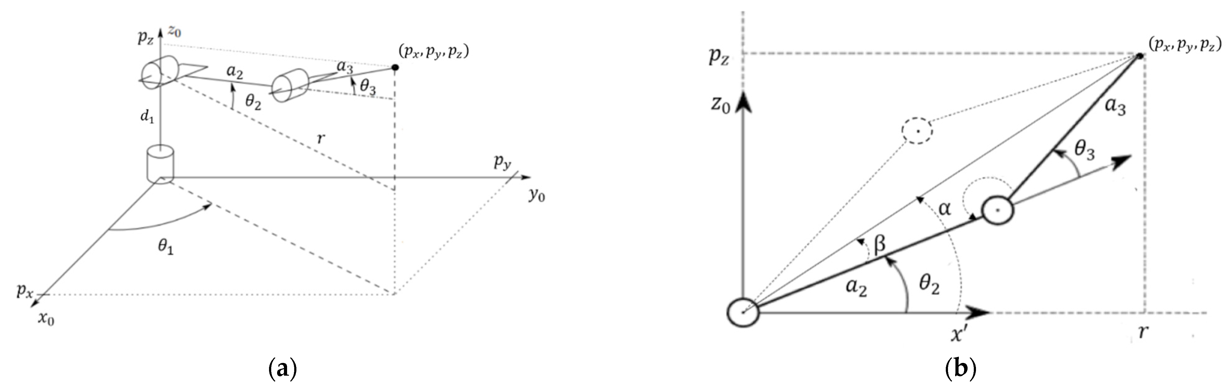
The geometric representation shown in Figure 2 is used to obtain the inverse kinematics, where two possible poses of the manipulator have been represented to reach the desired position of the end effector. From Figure 2, the Expressions (5) and (6) are derived.
where,
If a positive value of is taken, the lower posture shown in Figure 2 is selected, while if a negative value of is taken, the upper posture is selected. The value of is obtained by the following expressions:
Equations (5), (6), and (8) constitute the inverse kinematic model of the 3-DoF manipulator.
2.2. Dynamic Robot Model
The dynamics deals with the relationship between the forces acting on a body and the resulting motion. Therefore, the dynamic model of a robot aims to understand the relationship between the robot’s motion and the forces involved in it [33].
Using the Lagrange–Euler formulation, the dynamic model of an n-DoF manipulator can be expressed by Equation (11) [31].
denotes the inertia matrix, represents the matrix of the Coriolis terms, corresponds to the vector of gravitational torques of the robot, and to the vector of frictional forces. represents the vector of generalized forces and represent the components of the position vector, velocity, and acceleration of the joints, respectively. The dynamic model of the 3-DoF manipulator is expressed by Equations (12) through (31).
3. Control Strategies Design
This section discusses the theoretical principles behind the control strategies that were examined. A comprehensive description of the parameters and considerations taken into account during the design of the controllers is provided, offering valuable insights for future research in the field.
3.1. Fuzzy Logic Controller
Contrary to traditional control methods, fuzzy logic-based schemes provide a more effective method for the analysis and control of nonlinear, time-varying systems that are relatively complex and difficult to model mathematically [34]. The Fuzzy Logic Controller allows to express the general characteristics of a non-linear system through linguistic expressions by the creation of IF-THEN rules [35].
Fuzzy Logic is a language that allows the translation of sophisticated natural language sentences into a mathematical formalism. Knowledge is acquired and manipulated in an inferential and deductive manner, through symbolic reasoning [36].
These systems work with fuzzy sets that do not have perfectly defined boundaries, with a gradual transition between the membership or non-membership of variables to a given set. The membership functions provide flexibility in modeling by means of the use of linguistic variables.
A fuzzy controller is composed of four main parts [37]:
- The first step in the fuzzy inference process is fuzzification. This is responsible for converting the controller inputs into fuzzy information that the inference mechanism can understand and process. In the transformation, each input has its set of membership functions. These functions must be representative of the variable; therefore, they cover all the possible values of the input;
- The knowledge base contains all the inference rules (IF-THEN rules) that characterize the control goals and the policy used by the experts to carry out the control;
- The inference mechanism refers to the computational procedure used to evaluate the fuzzy rules. It is the core of fuzzy logic control, as it is responsible for executing the knowledge base by generating the answers;
- The defuzzification interface maps the conclusions of the inference mechanism to obtain the control action. For this purpose, it uses membership functions analogous to those used by the fuzzifier.
The two most important and widely used methods in fuzzy inference are the Mamdani method and the Sugeno method. The main difference between these methods lies in the consequent part of the fuzzy logic rules. Mamdani-type fuzzy inference methods use fuzzy sets as the consequents for the rules, while Sugeno-type systems use linear functions [38].
A fuzzy controller is designed, implementing a three-channel independent control system. In this approach, each controller focuses on a specific joint, designed to minimize the influence of other joints. Detailed system modeling of the robot’s kinematics and dynamics is crucial for achieving a comprehensive understanding of the robot’s behavior and enables the management of coupling quantities between joints for efficient and decoupled control of each joint.
To establish independence between joints, fuzzy rules were designed for each joint, considering its state and desired behavior. Fuzzy inference calculates control signals for each joint based on its input channel, with the assurance that fuzzy rules do not directly couple control inputs from different joints. The controller was experimentally tuned by observing its behavior at each moment.
The fuzzy controller consists of 9 control knowledge rules. The joint error and its derivative are taken as inputs, and the output is defined as the torque to be applied to the plant input. The fuzzy controller was developed using the Mamdani inference method with the Fuzzy Logic Toolbox in MatLab. Three membership functions are defined for the inputs and five for the output, with trapezoidal-type functions at the corners and triangular type functions in the center.
The linguistic variables for the input are P, positive value; Z, zero value; and N, negative value. The linguistic variables for the output are: TPP, large positive torque; TP, positive torque; TZ, zero torque; TN, negative torque; an TNN, large negative torque. The rules of the fuzzy controller were implemented following the correspondences given in Table 2.
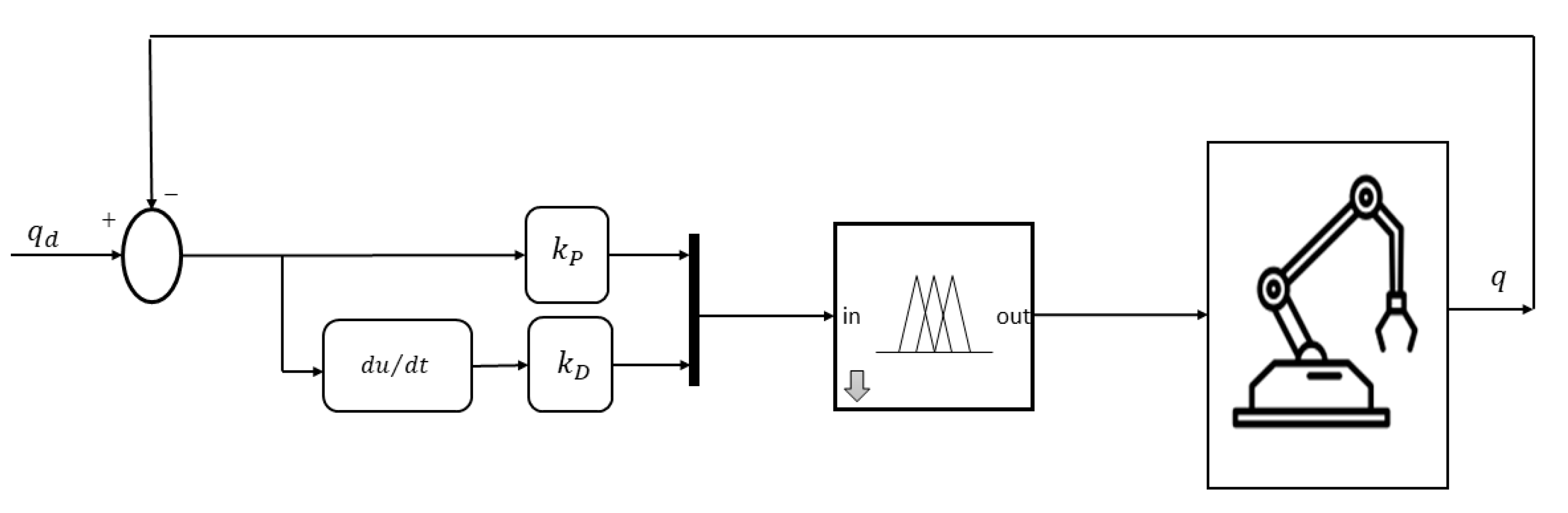
Figure 3 shows the scheme used in the implementation of the fuzzy controller. In Figure 4 the membership functions defined for each input and output of the controller are shown.
Table 3 shows the empirically obtained values corresponding to proportional and derivative controller gains for each joint.
3.2. ANFIS Controller
ANFIS are also fuzzy logic systems, which have been enhanced with learning, generalization, and adaptation capabilities.
The ANFIS inference system corresponds to a set of fuzzy IF-THEN rules in a neural network-like structure, which has learning capabilities to approximate nonlinear functions [39]. It is designed to construct membership functions that can accurately fit a predetermined input–output dataset while maintaining a minimal error tolerance. This process involves identifying and defining appropriate membership functions to represent the relationships between input and output variables [40]. The ANFIS is based on the Takagi–Sugeno fuzzy system method [41], where the final fuzzy inference system is optimized by training an ANN.
Due to its capacity to handle inaccuracy and uncertainty, the design of ANFIS can be based on real provided data [42]. The distinctive feature of ANFIS compared to standard fuzzy systems is that both the parameters of the premises and those of the consequents of the rules are adjustable.
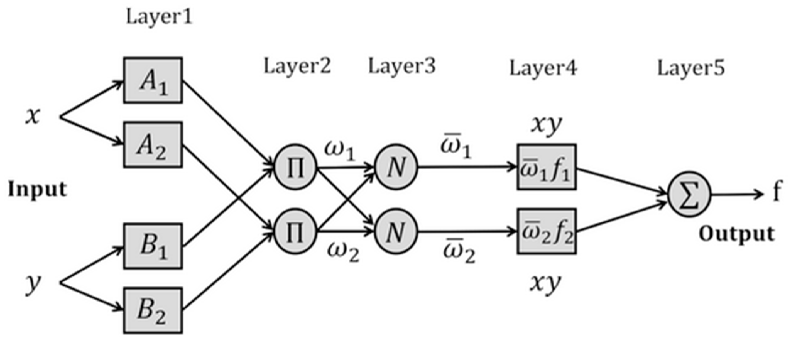
Figure 5 shows the architecture of the ANFIS network, where adaptive nodes (squares) and non-adaptive nodes (circles) can be distinguished. Nodes in layers 1 and 4 are adaptive since their premises and consequent parameters are modified during learning. The rest of the layers have non-adaptive nodes that implement basic functions such as sum, product, and normalization and have fixed parameters.
The hybrid learning procedure used mostly in training ANFIS networks is one of its most attractive features. In this procedure, the adaptation of network weights is divided into two steps. Firstly, the least-squares estimation (LSE) is used to identify the consequent parameters of the output functions. Secondly, the backpropagation gradient descent method is used to fine-tune the premise parameters of the membership functions.
For the design of the ANFIS controller in this work, a classic computed-torque control scheme has been taken as a basis. This scheme consists of applying torque to compensate for centrifugal and Coriolis effects, gravitational effects, and friction.
The implemented control law is described in Equation (32), where represent the estimates of the inertia matrix; the Coriolis matrix, the vector of gravitational forces, and the vector of frictional forces, respectively; and is described by Equation (33).
The positive definite and diagonal matrices, corresponding to the derivative and proportional gain, are represented by and , respectively. represent the position, velocity, and acceleration of the desired joint trajectory.
Considering small errors in the model estimates, the error in the joints can be approximated by Equation (34), a second-order linear differential equation.
ANFIS can be trained to implement Equation (32). However, it is more efficient to perform the training so that it learns the dynamic equation of the robot, and once this is completed, the controller is implemented by substituting the input corresponding to for Equation (33). In this way the training time is reduced considerably.
In this work, the ANFIS network is trained to learn the inverse dynamic model of the robot, using a total of 300,000 samples. To perform the training, it is of utmost importance to generate a dataset that allows for capturing as faithfully as possible the dynamics of the robot and mapping its motion space. The performance of the developed controller will depend on this. The more accurate the training datasets are, the more accurate ANFIS will be in estimating the required torques.
To select the type and number of membership functions, the combinations that offered the lowest error as a result of training and the better performance indices were determined. In the selection, greater weight was given to the value of the performance indices obtained, selecting the option that obtained the best tracking, without the presence of oscillations or overshoot.
In all cases, the training process involved utilizing 300 epochs, the Grid Partition option, and a hybrid optimization method.
Finally, the inference system was designed with 6 Gaussian membership functions for joint 1 and 5 Gaussian membership functions for joint 2 and 3. A constant membership function is used for the output since it reports better performance in Takagi–Sugeno type systems. The ANFIS controller was developed using the ‘anfisedit’ function of the Fuzzy Logic Toolbox of MatLab R2022b.
Figure 6 shows the diagram used in the implementation of the ANFIS controller. Table 4 shows the and gain values established.
The uniqueness of this approach lies in its ability to avoid direct numerical computation of dynamic effects compensation. By employing ANFIS as a function approximator, the system learns the complex relationship between the provided inputs and the required control torque, thereby enabling precise and smooth control of the robot.
3.3. Stability Analysis
Fuzzy controllers are widely acknowledged for their stability in the majority of cases. Their fuzzy structure enables efficient modeling and control of nonlinear and complex systems, demonstrating increased tolerance to system uncertainty and variability due to the absence of a precise mathematical model requirement. Both theoretical and practical evidence supports the idea that fuzzy controllers offer robustness and adaptability across various environments and applications. In dynamic and changing settings, fuzzy controllers have proven effective, showcasing their ability to adapt to different operating conditions while maintaining stability.
The stability of fuzzy controllers has been extensively analyzed in various references, such as [43,44,45,46,47], where BIBO (Bounded Input, Bounded Output) stability conditions are established using the well-known Small Gain Theorem. Many studies have shown that fuzzy controllers offer robustness and adaptability in dynamic and changing environments, indicating their ability to adapt to different operating conditions while remaining stable.
In addition to the existing literature supporting the stability of fuzzy systems, we conducted an experiment to further assess the stability of the system presented in this study. A new fuzzy controller was designed with membership functions, as depicted in Figure 7. The deliberate choice of a membership function with narrow central tendencies, close to zero at the input of the fuzzy controller, was made to investigate sensitivity to small variations in tracking error.
By narrowing the central membership function, the system’s sensitivity is focused on a specific range of the input signal. While this approach can effectively highlight and intensively respond to certain error ranges, it may also increase susceptibility to minor variations within those ranges. An extremely narrow central membership function can imbalance the influence of different rules in the system.
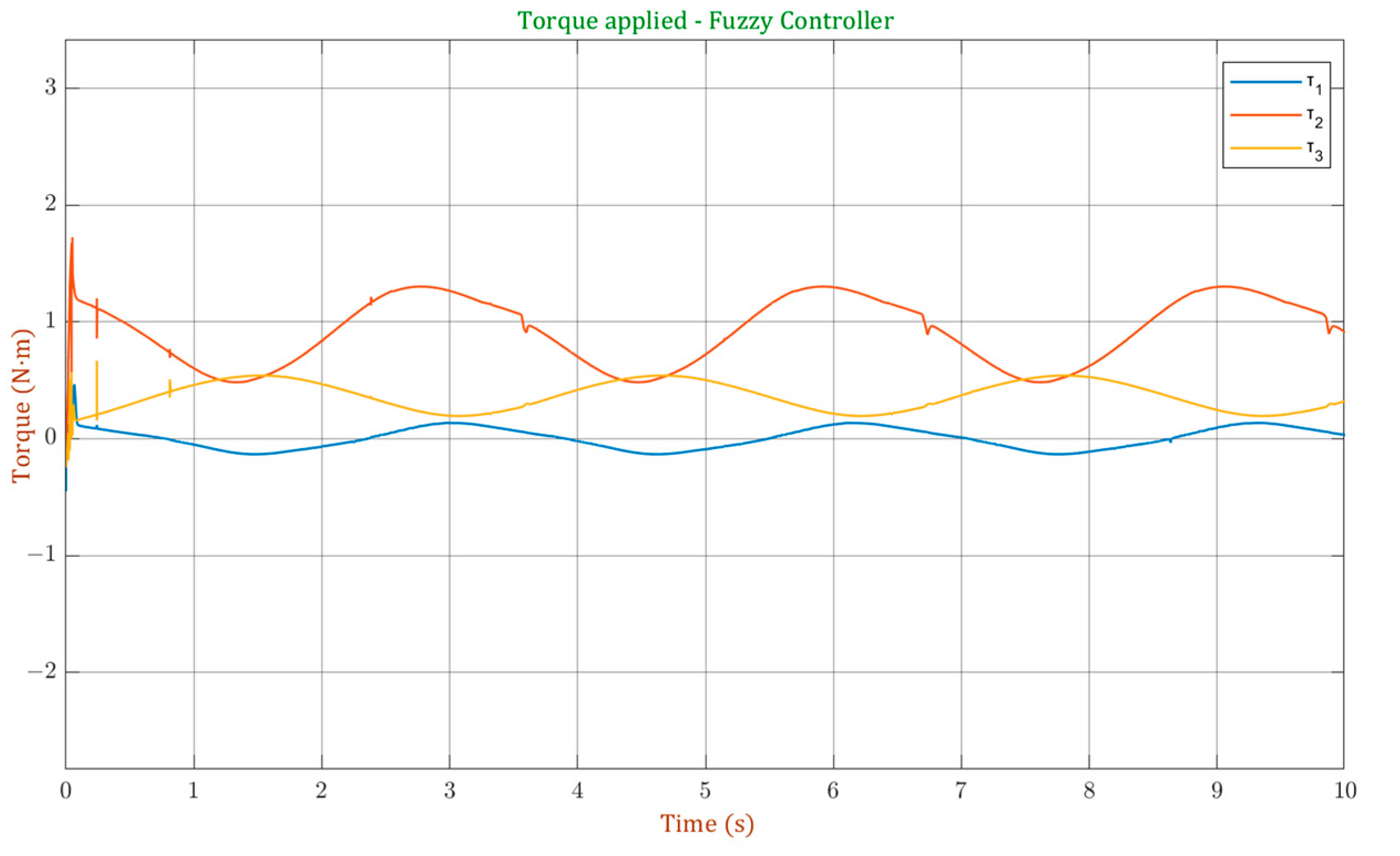
Examining Figure 8, displaying torque signals generated by this controller during tracking of a circular trajectory, constant torque saturations for all three joints are evident. In this design, the system’s stability is crucial, and the extreme sensitivity introduced by an extremely narrow membership function can result in abrupt and undesirable responses. The constant torque saturations observed in Figure 8 serve as an indicator that the system may not be stable.
In contrast, this behavior is not evident when analyzing the torque signal of the controller presented in this work, as illustrated in Figure 9. In this case, appropriate tracking curves and torque signals are exhibited, suggesting that these membership functions are more effective in providing stability to the system. The design choices, including membership function shapes, contribute to the stable performance of our controller, ensuring robust responses even under varying conditions.
4. Results and Discussions
In this section, the results from simulating the controllers applied to the robot are shown. The graphs for the tracking of two trajectories and the calculation of the performance indices are presented. A qualitative analysis of the obtained graphs is established, as well as a quantitative analysis through the performance indices: residual mean square value of the error and the integral of the absolute error weighted in time.
4.1. Simulation Environment
The performance of both controllers is evaluated in trajectory tracking. Two trajectories with sinusoidal type profiles in position and velocity are used. The trajectories are defined by Equations (37) and (38) and are represented in Figure 10.
Then, a load variation is applied during trajectory 2 tracking in order to analyze the robustness of the system and to observe its behavior in the rejection of external disturbances.
Latency and delays play a crucial role in the precise control of robots over time, and they can manifest in various stages of the control block [48]. The delay in input control can be attributed to various factors within the control system. Firstly, the dynamics of the actuator itself can introduce a delay, as it takes time for the actuator to respond and generate the desired control output. Additionally, the processing of data used for generating the control signal, such as sensor measurements and calculations, can contribute to input control delay. Delays in the transmission of sensor information can result from various factors, including signal processing, data acquisition, or communication systems.
Furthermore, delay can also arise from failures or malfunctions in electronic interface devices or data acquisition systems, which can impact the overall control loop response time. Additionally, when filtering out noise components from velocity or force measurements, there can be a phase shift that indirectly introduces a delay in the control system [49].
With the aim of carrying out a more realistic simulation, a delay of 3 milliseconds (ms) was incorporated between the plant and the controller. In this way, the simulations include the inherent delays in the control of a real robotic manipulator.
4.2. Performance Indices
Performance indices are quantitative measures that specify the cost of system operation as a function of error and energy. They are used to evaluate the dynamic behavior, the quality of the transient response and the stress of the controller [50].
These indices allow the measurement and quantification of different performance characteristics of a robotic manipulator. These metrics facilitate the study, evaluation, and optimization of the design, as well as the application of manipulator robots. Furthermore, they enable the establishment of comparisons between architectures and performance of different controllers or manipulators used in the same task [51].
To evaluate and compare the performance of the implemented controllers, performance indices were computed. The root mean square error (RMSE) was employed, providing a measure of the spread of errors between desired and actual positions of the robot. This index furnishes a comprehensive evaluation of the control model’s accuracy. Additionally, the integral of the absolute value of the time-weighted error (ITAE) was utilized. ITAE emphasizes steady-state error over the initial response [52], offering a holistic perspective on the controller’s performance. The expressions for calculating these indices are depicted in Equations (39) and (40).
4.3. Trajectory Tracking
This section shows the simulation plots of the two proposed trajectories, as well as the performance indices obtained for each case. Figure 11 illustrates the relationship between the desired Cartesian trajectory and the one traced by the robot using the fuzzy controller. Figure 12 shows the graph obtained for the joint trajectory.
It can be seen that a good tracking of the desired trajectory is achieved with this controller, which is proven by the rather small error values obtained. The error values are shown in Figure 13 and Figure 14 for the Cartesian trajectory and the joint trajectory respectively.
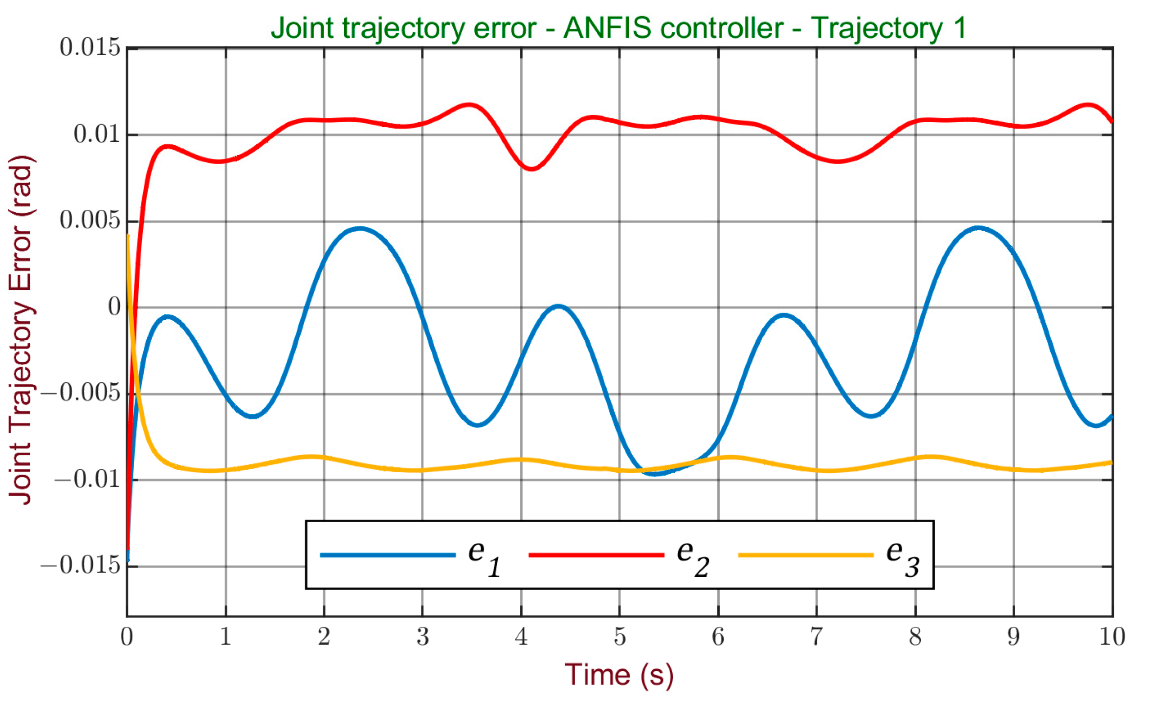
The tracking of trajectory 1 achieved with the ANFIS controller is illustrated in Figure 15, for the Cartesian space, and in Figure 16 for the joint trajectory. A good tracking of the reference is observed, without the presence of overshoots or oscillations, similarly to the result obtained with the fuzzy controller.
Figure 17 and Figure 18 show the error graphs obtained with ANFIS in the Cartesian and joint space. Small error values are obtained, considered acceptable, smaller values than those obtained with the fuzzy controller are observed.
The performance analysis of both controllers for trajectory 1 is carried out from Table 5, which shows the indices for the Cartesian trajectory, and Table 6, which shows the values obtained in the joint trajectory.
Based on these values, it can be stated that both controllers have good performance in tracking trajectory 1. However, a slight improvement is observed for the ANFIS controller. This finding is reinforced by the graphical representation in Figure 19, where a side-by-side comparison of the tracking curves for each joint indicates an improvement in accuracy achieved by the ANFIS controller in tracking trajectory 1.
Next, the results for the tracking of trajectory 2 are analyzed. Figure 20 and Figure 21 show the robot’s path using the fuzzy controller for the Cartesian trajectory and the joint trajectory, respectively.
In the case of Figure 21, it can be observed that this trajectory demands greater effort from the controller as it has a wider range of movement in each joint and along the z-axis, where it is necessary to compensate for interactions with gravity. By observing Figure 22 and Figure 23 of the Cartesian and joint errors, it can be verified that although error values are acceptable, they are slightly higher than those obtained with trajectory 1.
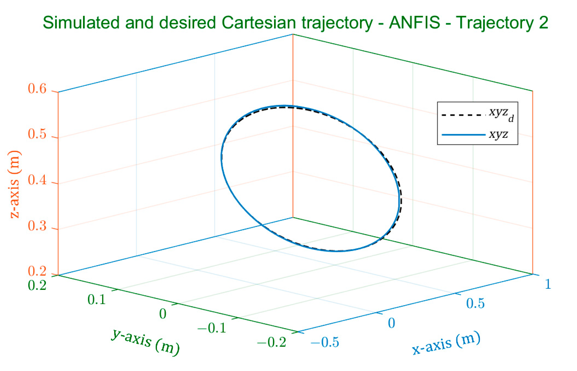
The results obtained with the ANFIS in the tracking of trajectory 2 are illustrated in Figure 24, for the Cartesian space, and in Figure 25 for the joint space.
The error plots obtained with ANFIS, shown in Figure 26 and Figure 27, show small error values, lower than those obtained with the fuzzy controller.
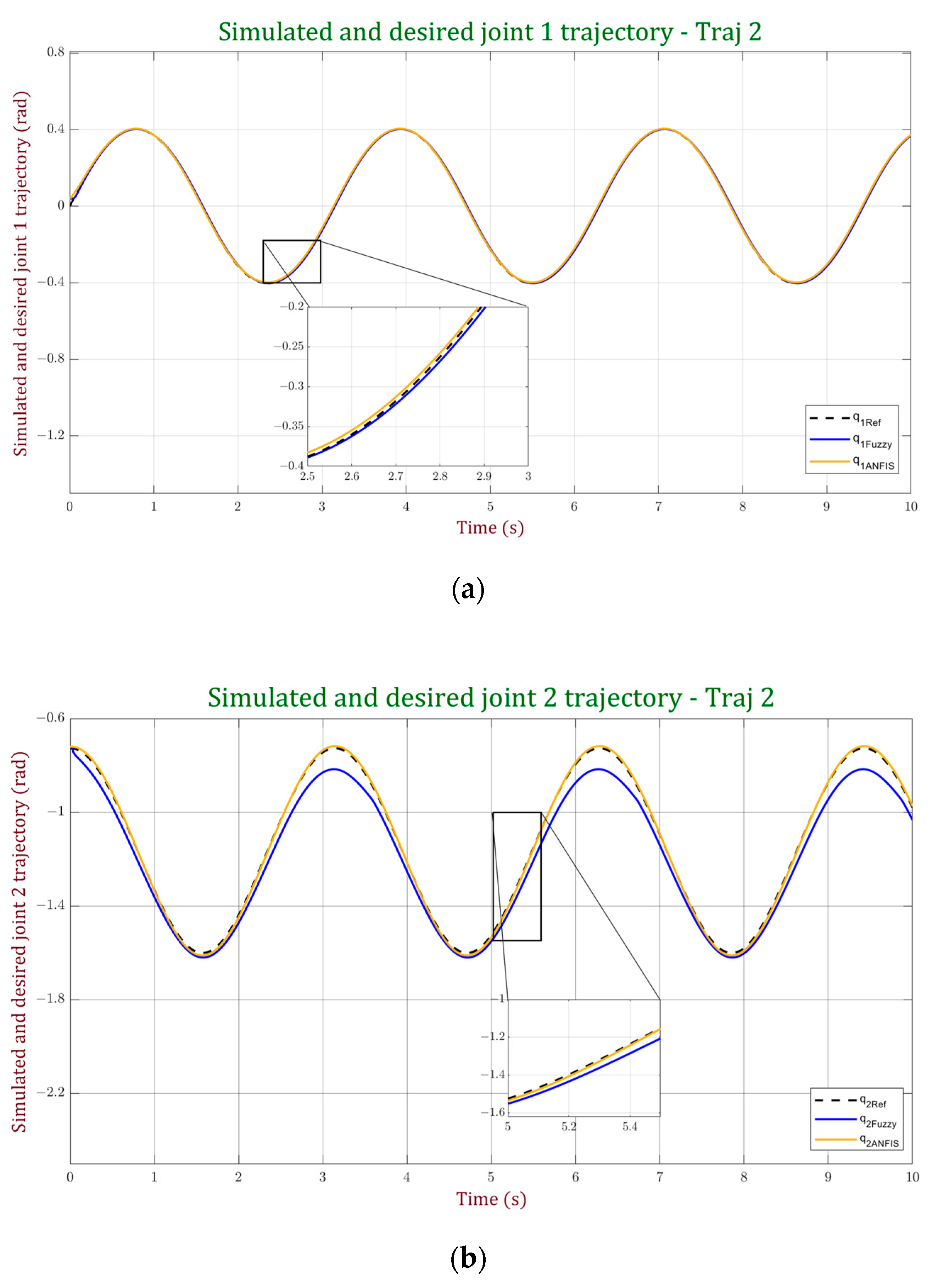
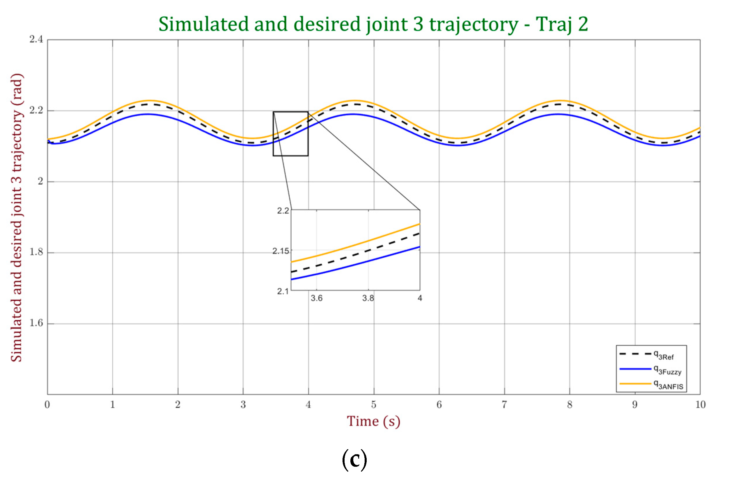
According to the values in Table 7 and Table 8, which show the performance indices obtained in trajectory 2 tracking, it can be concluded that both controllers exhibit good performance in tracking trajectory 2. However, a notably superior performance is observed for the ANFIS controller. This outcome is further supported by the graphs presented in Figure 28, where a detailed comparison between the two controllers is established through the tracking curves for each joint. It is evident from the graphs that the ANFIS controller achieves a significantly higher level of accuracy in tracking trajectory 2.
Table 9 provides a comprehensive comparison between the controllers developed in this study and recently published fuzzy controllers, utilizing performance indices as benchmarks. It is crucial to note that undertaking such comparisons poses challenges due to inherent variations in system complexity, degrees of freedom, trajectory considerations for performance measurement, and other specific aspects unique to each study. For the purpose of this comparison, we have calculated the average values of each index for the Cartesian trajectory 2.
From the analysis of Table 8, it can be concluded that the controllers developed in this study exhibit competitive performance compared to those proposed by other authors, with the ANFIS standing out as having the best ITAE index and the second-best RMSE. Furthermore, it is concluded that the application of optimization techniques in defining fuzzy sets significantly enhances the performance of fuzzy controllers, as evidenced in [53], where the parameters of the proposed controller are tuned using the Archimedes Optimization Algorithm (AOA).
Additionally, the designed controllers in this work are characterized by their simplicity, which has proven to be a valuable attribute, yielding robust and effective results. The inherent simplicity of these controllers offers several significant advantages. It facilitates system understanding, adjustment, and implementation, streamlining the process and enhancing operational efficiency. Furthermore, it contributes to system reliability and stability by reducing complexity.
4.4. External Disturbances
In order to analyze the robustness of the two designed controllers, a perturbation was applied to the system during the tracking of trajectory 2. This perturbation consisted of adding a 0.3 kg load on the third joint after 5 s of simulation. Figure 29 and Figure 30 correspond to the tracking of the joint trajectory obtained in the presence of this disturbance for the fuzzy and ANFIS controller, respectively.
It can be observed that the fuzzy controller exhibits a significant deterioration in trajectory tracking in the second and third joints when the increase in mass in the third link is introduced. This indicates that the fuzzy controller struggles to adapt to changes in the system dynamics and fails to adequately capture the complex and nonlinear interactions between system variables. As a result, its ability to handle external disturbances or variations in system parameters may be limited.
On the other hand, a more robust response to the increase in mass, in terms of trajectory tracking, is observed with the ANFIS controller, as the effect is significantly reduced compared to the fuzzy controller. This is because ANFIS has the capability to adjust its internal parameters based on the information provided by the input and output data of the system, allowing it to better adapt to the dynamic characteristics of the system.
On positive slopes, where the trajectory is ascending, the interaction between the increased mass and the gravitational force poses a particularly challenging scenario for both the fuzzy and ANFIS controllers.
Rising slopes introduce additional complexities to the control problem due to the combined effects of gravity and the increased inertia of the system. These factors create difficulties in generating precise torque commands to compensate for the augmented mass during upward motion.
The fuzzy controller’s difficulty in precisely modeling the nonlinear dynamics of the system can hinder its ability to compensate for the effects of increased mass on rising slopes. The imprecise modeling can lead to deviations in torque generation, resulting in degraded trajectory tracking performance. Similarly, while the ANFIS controller exhibits a more robust response to the increased mass, it still faces challenges in fully correcting the torque signal on uphill slopes due to the intricate dynamics involved.
Figure 31 illustrates the torque graph generated by the fuzzy controller. It can be seen that the compensations generated by this controller, due to the increase in load, allow the joints to maintain a relatively smooth oscillatory behavior. There is no significant actuator saturation observed. This characteristic indicates that the fuzzy controller is capable of generating control commands that partially compensate for the effects of the increased mass, resulting in a smoother response from the actuators.
In contrast, the analysis of the torque graph generated by the ANFIS controller, as depicted in Figure 32, reveals a notable saturation of the torque signal for a considerable duration. This observation sheds light on a significant limitation of the ANFIS controller when faced with the increased mass scenario. Despite its ability to adapt to changes in system dynamics, the ANFIS controller struggles to generate precise control commands that adequately compensate for the effects of the augmented mass. The saturation of the torque signal suggests a restricted operational range or imprecise modeling of the system dynamics, hampering the controller’s ability to deliver optimal performance in such conditions.
The performance indices were recalculated for these conditions. The new values obtained are shown in Table 10, for Cartesian space, and in Table 11 for joint space.
In the presence of this variation in the load, a variation in the indices with respect to those obtained in the trajectory tracking is observed. In this test, much higher values of the ITAE are observed in comparison with the rest of the tests, considering that this index is an indicator of the time it takes for the system to recover from an error.
5. Conclusions
In this study, a comprehensive and comparative evaluation of two intelligent control strategies was conducted, specifically the Fuzzy Logic Controller and the Adaptive Neuro-Fuzzy Inference System (ANFIS), tailored for a 3-DoF robotic arm operating in the context of Industry 4.0. The examination focused on assessing the precision and overall performance of both controllers, particularly in trajectory tracking scenarios.
The results of these evaluations consistently demonstrated that both controllers exhibited commendable performance in the functional tests. Notably, they successfully achieved accurate tracking of the predefined reference trajectory without any observed oscillations or overshoots. This consistent and reliable performance underscores the controllers’ effectiveness in meeting the demands of the given scenarios.
The application of the ITAE and RMSE performance indices further verified the precision attained by the controllers. Specifically, the ANFIS controller demonstrated superior performance compared to the fuzzy controller, as indicated by its ability to achieve the smallest indices in the tests. This outcome was validated through a meticulous comparison with recently published fuzzy controllers.
The ANFIS controller showcases remarkable efficiency in achieving precise trajectory tracking and effective regulation, even in the face of load variations within the robotic arm system. This adaptability holds significant implications for a broad spectrum of robotic applications, particularly in scenarios involving complex manipulation tasks such as palletizing in the logistics industry. The ability of the ANFIS controller to dynamically adapt to variations in the weight and size of products is crucial for tasks like assembly, where the payload may vary due to the manipulation of components with different sizes and weights. Similarly, in automated loading and unloading applications, such as those seen in robotic warehouses, the ANFIS controller proves to be a versatile and reliable solution.
For future research, the aim is to continue evolving controllers for robotic arms, aligning with the precision and autonomy requirements of Industry 4.0 standards. An exciting avenue for exploration involves the potential integration of bio-inspired controllers, particularly those based on Spiking Neural Networks, which could emulate the information processing capabilities of the human brain and further enhance the capabilities of robotic systems.
Author Contributions
Conceptualization, J.K. and D.M.; methodology, J.K. and D.M.; software, J.K. and D.M.; validation, J.K. and D.M.; formal analysis, J.K. and D.M.; investigation, J.K. and D.M.; resources, J.K. and D.M.; data curation, J.K. and D.M.; writing—original draft preparation, J.K. and D.M.; writing—review and editing, J.K. and D.M.; visualization, J.K. and D.M.; supervision, J.K. and C.U.; project administration, J.K. and C.U.; funding acquisition, J.K. and C.U. All authors have read and agreed to the published version of the manuscript.
Funding
This research received no external funding.
Data Availability Statement
Data are contained within the article.
Acknowledgments
This work has been supported by Agencia Nacional de Investigación y Desarrollo ANID, Chile, through IDeA I + D ID21I10087 project and by ANID-Subdirección de Capital Humano/Doctorado Nacional/2021- 21210149. It also received support from the Vicerrectoría de Investigación, Innovación y Creación of the University of Santiago of Chile (USACH), Chile.
Conflicts of Interest
The authors declare no conflict of interest.
References
- Czimmermann, T.; Chiurazzi, M.; Milazzo, M.; Roccella, S.; Barbieri, M.; Dario, P.; Oddo, C.M.; Ciuti, G. An Autonomous Robotic Platform for Manipulation and Inspection of Metallic Surfaces in Industry 4.0. IEEE Trans. Autom. Sci. Eng. 2022, 19, 1691–1706. [Google Scholar] [CrossRef]
- Galin, R.; Meshcheryakov, R. Automation and Robotics in the Context of Industry 4.0: The Shift to Collaborative Robots. IOP Conf. Ser. Mater. Sci. Eng. 2019, 537, 032073. [Google Scholar] [CrossRef]
- Chotikunnan, P.; Chotikunnan, R.; Nirapai, A.; Wongkamhang, A.; Imura, P.; Sangworasil, M. Optimizing Membership Function Tuning for Fuzzy Control of Robotic Manipulators Using PID-Driven Data Techniques. J. Robot. Control 2023, 4, 128–140. [Google Scholar] [CrossRef]
- Bryndin, E. Increase of Safety Use Robots in Industry 4.0 by Developing Sensitivity and Professional Behavioral Skills. Am. J. Mech. Ind. Eng. 2020, 5, 6. [Google Scholar] [CrossRef]
- González-Rodríguez, A.; Baray-Arana, R.E.; Rodríguez-Mata, A.E.; Robledo-Vega, I.; Acosta Cano de los Ríos, P.R. Validation of a Classical Sliding Mode Control Applied to a Physical Robotic Arm with Six Degrees of Freedom. Processes 2022, 10, 2699. [Google Scholar] [CrossRef]
- Rawat, D.; Gupta, M.K.; Sharma, A. Intelligent Control of Robotic Manipulators: A Comprehensive Review. Spat. Inf. Res. 2023, 31, 345–357. [Google Scholar] [CrossRef]
- Hentout, A.; Maoudj, A.; Aouache, M. A Review of the Literature on Fuzzy-Logic Approaches for Collision-Free Path Planning of Manipulator Robots. Artif. Intell. Rev. 2023, 56, 3369–3444. [Google Scholar] [CrossRef]
- Eckert, J.J.; Barbosa, T.P.; Silva, F.L.; Roso, V.R.; Silva, L.C.; da Silva, L.A.R. Optimum Fuzzy Logic Controller Applied to a Hybrid Hydraulic Vehicle to Minimize Fuel Consumption and Emissions. Expert Syst. Appl. 2022, 207, 117903. [Google Scholar] [CrossRef]
- Bi, M. Control of Robot Arm Motion Using Trapezoid Fuzzy Two-Degree-of-Freedom PID Algorithm. Symmetry 2020, 12, 665. [Google Scholar] [CrossRef]
- Hernandez-Mendez, S.; Palacios-Hernandez, E.R.; Marin-Hernandez, A.; Rechy-Ramirez, E.J.; Vazquez-Leal, H. Design and Implementation of Composed Position/Force Controllers for Object Manipulation. Appl. Sci. 2021, 11, 9827. [Google Scholar] [CrossRef]
- Gonzalez-Villagomez, J.; Rodriguez-Donate, C.; Lopez-Ramirez, M.; Mata-Chavez, R.I.; Palillero-Sandoval, O. Novel Iterative Feedback Tuning Method Based on Overshoot and Settling Time with Fuzzy Logic. Processes 2023, 11, 694. [Google Scholar] [CrossRef]
- Karahan, O.; Ataşlar-Ayyıldız, B. Optimal Design of Fuzzy PID Control. In Intelligent Computing; Arai, K., Kapoor, S., Bhatia, R., Eds.; Springer International Publishing: Cham, Switzerland, 2019; pp. 174–188. [Google Scholar]
- Muñoz-Vázquez, A.J.; Gaxiola, F.; Martínez-Reyes, F.; Manzo-Martínez, A. A Fuzzy Fractional-Order Control of Robotic Manipulators with PID Error Manifolds. Appl. Soft Comput. 2019, 83, 105646. [Google Scholar] [CrossRef]
- Mohamed, M.; Abdul Samad, B.; Anayi, F.; Packianather, M.; Yahya, K. Analysing Various Control Technics for Manipulator Robotic System (Robogymnast). Comput. Mater. Contin. 2023, 75, 4681–4696. [Google Scholar] [CrossRef]
- Chang, W.-J.; Lin, Y.-W.; Lin, Y.-H.; Pen, C.-L.; Tsai, M.-H. Actuator Saturated Fuzzy Controller Design for Interval Type-2 Takagi-Sugeno Fuzzy Models with Multiplicative Noises. Processes 2021, 9, 823. [Google Scholar] [CrossRef]
- El-Nagar, A.M.; Abdrabou, A.; El-Bardini, M.; Elsheikh, E.A. Embedded Fuzzy PD Controller for Robot Manipulator. In Proceedings of the 2021 International Conference on Electronic Engineering (ICEEM), Menouf, Egypt, 3–4 July 2021; pp. 1–6. [Google Scholar]
- Zhang, L.; Yang, G.-H. Low-Computation Adaptive Fuzzy Tracking Control for Nonlinear Systems via Switching-Type Adaptive Laws. IEEE Trans. Fuzzy Syst. 2019, 27, 1931–1942. [Google Scholar] [CrossRef]
- Zhang, J.-X.; Yang, G.-H. Low-Computation Adaptive Fuzzy Tracking Control of Unknown Nonlinear Systems With Unmatched Disturbances. IEEE Trans. Fuzzy Syst. 2020, 28, 321–332. [Google Scholar] [CrossRef]
- Zhou, P.; Zhang, L.; Zhang, S.; Alkhateeb, A.F. Observer-Based Adaptive Fuzzy Finite-Time Control Design With Prescribed Performance for Switched Pure-Feedback Nonlinear Systems. IEEE Access 2021, 9, 69481–69491. [Google Scholar] [CrossRef]
- Liu, K.; Yang, P.; Wang, R.; Jiao, L.; Li, T.; Zhang, J. Observer-Based Adaptive Fuzzy Finite-Time Attitude Control for Quadrotor UAVs. IEEE Trans. Aerosp. Electron. Syst. 2023, 1–17. [Google Scholar] [CrossRef]
- Lai, K.L.; Vu, N.H.; Lai, T.H. The Hedge-Algebras-Based Controller for Robotic Arm. In Advances in Engineering Research and Application; Fujita, H., Nguyen, D.C., Vu, N.P., Banh, T.L., Puta, H.H., Eds.; Springer International Publishing: Cham, Switzerland, 2019; pp. 572–579. [Google Scholar]
- Di Bello, P. Cartesian Control of a 3DoF Upper Limb Prosthetic Device. Master’s thesis, Politecnico di Torino, Torino, Italy, 2021. [Google Scholar]
- Rain, T.; Dovgal, V.M.; Soe, Y.N. Efficient Method for Inverse Dynamics of Robot Manipulators by Using Adaptive-Network-Based Fuzzy Inference System. In Proceedings of the 2019 International Conference on Industrial Engineering, Applications and Manufacturing (ICIEAM), Sochi, Russia, 25–29 March 2019; pp. 1–6. [Google Scholar]
- Barua, R.; Rahaman, S.; Shee, P.; Kumar, A.; Das, D.; Bhowmik, S. Analysis of Inverse Dynamics of 6-DOF Stanford Robotic Arm by Adaptive Neuro-Fuzzy Inference System (ANFIS). J. Mech. Robot. 2022, 7, 1–7. [Google Scholar]
- Abderrahim, B.; El Houssine, E.-C.M.; Hassan, S.; Hicham, A.E.; Bouras, A. Intelligent ANFIS Controller of Two Cooperative 3-DOF Manipulators: The Case of Manipulation under Non-Slip Constraints. In Proceedings of the 2022 2nd International Conference on Innovative Research in Applied Science, Engineering and Technology (IRASET), Meknes, Morocco, 3–4 March 2022; pp. 1–7. [Google Scholar]
- Ortatepe, Z.; Parlaktuna, O. Two Dof Robot Control With Fuzzy Based Neural Networks. Anadolu Univ. J. Sci. Technol.-Appl. Sci. Eng. 2017, 18, 819–830. [Google Scholar] [CrossRef]
- Wang, Z.; Zou, L.; Su, X.; Luo, G.; Li, R.; Huang, Y. Hybrid Force/Position Control in Workspace of Robotic Manipulator in Uncertain Environments Based on Adaptive Fuzzy Control. Robot. Auton. Syst. 2021, 145, 103870. [Google Scholar] [CrossRef]
- Han, J.; Wang, F.; Sun, C. Trajectory Tracking Control of a Manipulator Based on an Adaptive Neuro-Fuzzy Inference System. Appl. Sci. 2023, 13, 1046. [Google Scholar] [CrossRef]
- Spong, M.W.; Hutchinson, S.; Vidyasagar, M. Robot Modeling and Control; John Wiley & Sons: Hoboken, NJ, USA, 2020; ISBN 978-1-119-52399-4. [Google Scholar]
- Pascal Mamani, J.L. Estudio Y Simulación De Técnicas De Identificación De Parámetros Para Un Robot Tipo Scara. Bachelor’s Thesis, Universidad de Santiago de Chile, Santiago, Chile, 2015. [Google Scholar]
- García López, E. Desarrollo de Un Sistema de Rehabilitación Bilateral Asistido Por Robots. Master’s thesis, Centro de investigación y de estudios avanzados del instituto politécnico nacional, Mexico City, Mexico, 2017. [Google Scholar]
- Cardoso, E.; Fernández, A.; Marrero-Osorio, S.A.; Guardado, P.F. Modelos cinemático y dinámico de un robot de cuatro grados de libertad. Ing. Electrónica Automática Comun. 2017, 38, 56–75. [Google Scholar]
- Montalvo, W.; Escobar-Naranjo, J.; Garcia, C.A.; Garcia, M.V. Low-Cost Automation for Gravity Compensation of Robotic Arm. Appl. Sci. 2020, 10, 3823. [Google Scholar] [CrossRef]
- Abdul-Sadah, A.M.; Raheem, K.M.H.; Altufaili, M.M.S. A Fuzzy Logic Controller for a Three Links Robotic Manipulator. AIP Conf. Proc. 2022, 2386, 050026. [Google Scholar] [CrossRef]
- Inayathullaah, M.A.; Sivakumar, N.; Balasundaram, A.; Arul, R.; Angalaeswari, S. Time Domain Investigation of Hybrid Intelligent Controllers Fed Five-Phase PMBLDC Motor Drive. Appl. Sci. 2023, 13, 3281. [Google Scholar] [CrossRef]
- Thakur, A. Neuro-Fuzzy: Artificial Neural Networks & Fuzzy Logic. Int. J. Res. Appl. Sci. Eng. Technol. 2021, 9, 128–135. [Google Scholar] [CrossRef]
- Ledeneva, T. Special Aspects of the Design of Fuzzy Inference Mechanism. In Proceedings of the 2020 2nd International Conference on Control Systems, Mathematical Modeling, Automation and Energy Efficiency (SUMMA), Lipetsk, Russia, 11–13 November 2020; pp. 128–132. [Google Scholar]
- Alonso Fernández, F. Relación Entre Los Métodos de Inferencia Difusa y La Programación Lógica Multiadjunta. Bachelor’s Thesis, Universidad de Cádiz, Cádiz, Spain, 2019. [Google Scholar]
- Wang, X.; Abtahi, S.M.; Chahari, M.; Zhao, T. An Adaptive Neuro-Fuzzy Model for Attitude Estimation and Control of a 3 DOF System. Mathematics 2022, 10, 976. [Google Scholar] [CrossRef]
- Chawla, I.; Chopra, V.; Singla, A. Performance Comparison of PID and ANFIS Controller for Stabilization of x and X-y Inverted Pendulums. In Intelligent Systems Design and Applications; Abraham, A., Cherukuri, A.K., Melin, P., Gandhi, N., Eds.; Springer International Publishing: Cham, Switzerland, 2020; pp. 182–192. [Google Scholar]
- Ramos-Fernández, J.C.; López-Morales, V.; Márquez-Vera, M.A.; Pérez, J.M.X.; Suarez-Cansino, J. Neuro-Fuzzy Modelling and Stable PD Controller for Angular Position in Steering Systems. Int. J. Automot. Technol. 2021, 22, 1495–1503. [Google Scholar] [CrossRef]
- Abtahi, S.; Sharifi, M. Machine Learning Method Used to Find Discrete and Predictive Treatment of Cancer. arXiv 2020, arXiv:2004.09753. [Google Scholar]
- Zhang, X.; Li, S.; Li, H. Structure and BIBO Stability of a Three-Dimensional Fuzzy Two-Term Control System. Math. Comput. Simul. 2010, 80, 1985–2004. [Google Scholar] [CrossRef]
- Mohan, B.M.; Sinha, A. The Simplest Fuzzy PID Controllers: Mathematical Models and Stability Analysis. Soft Comput. 2006, 10, 961–975. [Google Scholar] [CrossRef]
- Wang, N.; Meng, X. Analytical Structures and Stability Analysis of Three-Dimensional Fuzzy Controllers. In Proceedings of the 2008 IEEE International Conference on Fuzzy Systems (IEEE World Congress on Computational Intelligence), Hong Kong, China, 1–6 June 2008; pp. 64–69. [Google Scholar]
- Chen, G.; Ying, H. BIBO Stability of Nonlinear Fuzzy PI Control Systems. J. Intell. Fuzzy Syst. 1997, 5, 245–256. [Google Scholar] [CrossRef]
- Malki, H.A.; Li, H.; Chen, G. New Design and Stability Analysis of Fuzzy Proportional-Derivative Control Systems. IEEE Trans. Fuzzy Syst. 1994, 2, 245–254. [Google Scholar] [CrossRef]
- Abadía, I.; Naveros, F.; Ros, E.; Carrillo, R.R.; Luque, N.R. A Cerebellar-Based Solution to the Nondeterministic Time Delay Problem in Robotic Control. Sci. Robot. 2021, 6, eabf2756. [Google Scholar] [CrossRef] [PubMed]
- Kang, Y.; Li, Z.; Cao, X.; Zhai, D. Robust Control of Motion/Force for Robotic Manipulators With Random Time Delays. IEEE Trans. Control Syst. Technol. 2013, 21, 1708–1718. [Google Scholar] [CrossRef]
- Velásquez Lobo, M.F. Control En Modo Deslizante Con Estimación de La Perturbación Aplicado a La Marcha de Un Robot. Master’s Thesis, Instituto Nacional de Astrofísica, Óptica y Electrónica: Puebla, Mexico, 2013. [Google Scholar]
- Patel, S.; Sobh, T. Manipulator Performance Measures—A Comprehensive Literature Survey. J. Intell. Robot. Syst. 2015, 77, 547–570. [Google Scholar] [CrossRef]
- Liu, K.; Wang, R.; Zheng, S.; Dong, S.; Sun, G. Fixed-Time Disturbance Observer-Based Robust Fault-Tolerant Tracking Control for Uncertain Quadrotor UAV Subject to Input Delay. Nonlinear Dyn. 2022, 107, 2363–2390. [Google Scholar] [CrossRef]
- Aouaichia, A.; Kara, K.; Ghoul, A. An Optimized Fuzzy Computed Torque Control for the Robot Manipulator PUMA 560. In Proceedings of the 2023 International Conference on Advances in Electronics, Control and Communication Systems (ICAECCS), Blida, Algeria, 6–7 March 2023; pp. 1–7. [Google Scholar]
Figure 1.
Axis assignment and D-H parameters for the 3-DoF robot. The visual representation highlights the axis arrangement and clear definition of D-H parameters, offering a quick and comprehensible insight into the geometric configuration of the robot [31].
Figure 1.
Axis assignment and D-H parameters for the 3-DoF robot. The visual representation highlights the axis arrangement and clear definition of D-H parameters, offering a quick and comprehensible insight into the geometric configuration of the robot [31].

Figure 2.
Geometric representation and postures for inverse kinematics of the robotic arm: (a) geometric representation; (b) geometric representation of the manipulator with two possible postures [32].
Figure 2.
Geometric representation and postures for inverse kinematics of the robotic arm: (a) geometric representation; (b) geometric representation of the manipulator with two possible postures [32].

Figure 3.
Schematic diagram used in the implementation of the Fuzzy Logic Controller.

Figure 4.
Membership functions of the fuzzy control: (a) membership functions for the input variable Error; (b) membership functions for the input variable error derivative (dError); (c) membership functions for the output variable Torque.
Figure 4.
Membership functions of the fuzzy control: (a) membership functions for the input variable Error; (b) membership functions for the input variable error derivative (dError); (c) membership functions for the output variable Torque.


Figure 5.
ANFIS structure [39].
Figure 5.
ANFIS structure [39].

Figure 6.
Schematic diagram used in the implementation of the ANFIS controller.

Figure 7.
Membership functions of a new fuzzy controller designed to make inferences about the stability of the system: (a) Membership functions for the input variable ‘error’; (b) membership functions for the input variable ‘error derivative’.
Figure 7.
Membership functions of a new fuzzy controller designed to make inferences about the stability of the system: (a) Membership functions for the input variable ‘error’; (b) membership functions for the input variable ‘error derivative’.

Figure 8.
Torque signal generated during the tracking of a circular trajectory by the new fuzzy controller designed to make inferences about the stability of the system.
Figure 8.
Torque signal generated during the tracking of a circular trajectory by the new fuzzy controller designed to make inferences about the stability of the system.

Figure 9.
Torque signal generated during the tracking of a circular trajectory by the fuzzy controller designed in the study.
Figure 9.
Torque signal generated during the tracking of a circular trajectory by the fuzzy controller designed in the study.

Figure 10.
Test trajectories: (a) Trajectory 1; (b) Trajectory 2.

Figure 11.
Simulated and desired Cartesian trajectory with the fuzzy controller for trajectory 1.

Figure 12.
Simulated and desired joint trajectory with the fuzzy controller for trajectory 1.

Figure 13.
Cartesian trajectory error with the fuzzy controller for trajectory 1.

Figure 14.
Joint trajectory error with the fuzzy controller for trajectory 1.

Figure 15.
Simulated and desired Cartesian trajectory with the ANFIS controller for trajectory 1.

Figure 16.
Simulated and desired joint trajectory with the ANFIS controller for trajectory 1.

Figure 17.
Cartesian trajectory error with the ANFIS controller for trajectory 1.

Figure 18.
Joint trajectory error with the ANFIS controller for trajectory 1.

Figure 19.
Joint trajectory performance comparison of the of controllers for trajectory 1. (a) Performance comparison for joint; (b) performance comparison for joint 2; (c) performance comparison for joint 3.
Figure 19.
Joint trajectory performance comparison of the of controllers for trajectory 1. (a) Performance comparison for joint; (b) performance comparison for joint 2; (c) performance comparison for joint 3.


Figure 20.
Simulated and desired Cartesian trajectory with the fuzzy controller for trajectory 2.

Figure 21.
Simulated and desired joint trajectory with the fuzzy controller for trajectory 2.

Figure 22.
Cartesian trajectory error with the fuzzy controller for trajectory 2.

Figure 23.
Joint trajectory error with the fuzzy controller for trajectory 2.

Figure 24.
Simulated and desired Cartesian trajectory with the ANFIS controller for trajectory 2.

Figure 25.
Simulated and desired joint trajectory with the ANFIS controller for trajectory 2.

Figure 26.
Cartesian trajectory error with the ANFIS controller for trajectory 2.

Figure 27.
Joint trajectory error with the ANFIS controller for trajectory 2.

Figure 28.
Joint trajectory performance comparison of the of controllers for trajectory 2: (a) performance comparison for joint 2; (b) performance comparison for joint 2; (c) performance comparison for joint 2.
Figure 28.
Joint trajectory performance comparison of the of controllers for trajectory 2: (a) performance comparison for joint 2; (b) performance comparison for joint 2; (c) performance comparison for joint 2.


Figure 29.
Simulated and desired joint trajectory with the fuzzy controller for trajectory 2 in the presence of external disturbances.
Figure 29.
Simulated and desired joint trajectory with the fuzzy controller for trajectory 2 in the presence of external disturbances.

Figure 30.
Simulated and desired joint trajectory with the ANFIS controller for trajectory 2 in the presence of external disturbances.
Figure 30.
Simulated and desired joint trajectory with the ANFIS controller for trajectory 2 in the presence of external disturbances.

Figure 31.
Torque signal applied to the robot using the fuzzy controller for trajectory 2 in the presence of load disturbances.
Figure 31.
Torque signal applied to the robot using the fuzzy controller for trajectory 2 in the presence of load disturbances.

Figure 32.
Torque signal applied to the robot using the ANFIS controller for trajectory 2 in the presence of load disturbances.
Figure 32.
Torque signal applied to the robot using the ANFIS controller for trajectory 2 in the presence of load disturbances.


Table 1.
D-H parameters of the 3-DoF manipulator.
| Joint | ||||
|---|---|---|---|---|
| 1 | 0 | |||
| 2 | 0 | 0 | ||
| 3 | 0 | 0 |
Table 2.
Fuzzy Logic Controller inference rule base.
| P | Z | N | ||
|---|---|---|---|---|
| P | TPP | TP | TZ | |
| Z | TP | TZ | TN | |
| N | TZ | TN | TNN | |
Table 3.
Fuzzy Logic Controller gains.
| Joint | ||
|---|---|---|
| 1 | 3.2 | 3.1 |
| 2 | 7.8 | 7.5 |
| 3 | 5.8 | 5.5 |
Table 4.
ANFIS controller gains.
| Joint | ||
|---|---|---|
| 1 | 700 | 70 |
| 2 | 800 | 80 |
| 3 | 900 | 90 |
Table 5.
Performance indices for Cartesian trajectory 1.
| ITAE | RMSE | |||
|---|---|---|---|---|
| Fuzzy | ANFIS | Fuzzy | ANFIS | |
| 0.2267 | 0.1373 | 0.0045 | 0.0029 | |
| 0.2302 | 0.0901 | 0.0045 | 0.0020 | |
| 0.5047 | 0.0279 | 0.0106 | 6.1412 × 10⁻⁴ | |
Table 6.
Performance indices for joint trajectory 1.
| ITAE | RMSE | |||
|---|---|---|---|---|
| Fuzzy | ANFIS | Fuzzy | ANFIS | |
| 0.0441 | 0.2116 | 0.0016 | 0.0047 | |
| 0.8575 | 0.5201 | 0.0189 | 0.0099 | |
| 0.9341 | 0.4584 | 0.0184 | 0.0090 | |
Table 7.
Performance indices for Cartesian trajectory 2.
| ITAE | RMSE | |||
|---|---|---|---|---|
| Fuzzy | ANFIS | Fuzzy | ANFIS | |
| 0.4673 | 0.1923 | 0.0087 | 0.0039 | |
| 0.1211 | 0.0825 | 0.0030 | 0.0023 | |
| 1.17 | 0.1052 | 0.0217 | 0.0023 | |
Table 8.
Performance indices for joint trajectory 2.
| ITAE | RMSE | |||
|---|---|---|---|---|
| Fuzzy | ANFIS | Fuzzy | ANFIS | |
| 0.1367 | 0.1213 | 0.0054 | 0.0047 | |
| 2.573 | 0.3517 | 0.0482 | 0.0079 | |
| 0.7583 | 0.4471 | 0.0174 | 0.0089 | |
Table 9.
Comparison between the performance of the controllers designed and results from other authors.
Table 9.
Comparison between the performance of the controllers designed and results from other authors.
| Controllers | DoF | Comparison Criterion | |
|---|---|---|---|
| ITAE | RMSE | ||
| Fuzzy-FO (fractional-order) [13] | 2 | 0.5812 | - |
| Fuzzy PID [12] | 3 | 0.4860 | - |
| Fuzzy LQR [14] | 3 | 0.313 | - |
| Fuzzy PID [28] | 4 | - | 0.0149 |
| ANFIS PID [28] | 4 | - | 0.00037 |
| Fuzzy PD [16] | 2 | - | 0.0316 |
| Optimized fuzzy computed torque [53] | 3 | - | 0.00458 |
| Proposed Fuzzy | 3 | 0.5861 | 0.01113 |
| Proposed ANFIS | 3 | 0.1266 | 0.0028 |
Table 10.
Performance indices for Cartesian trajectory 2 in the presence of external disturbances.
| ITAE | RMSE | |||
|---|---|---|---|---|
| Fuzzy | ANFIS | Fuzzy | ANFIS | |
| 1.337 | 0.2167 | 0.0261 | 0.0044 | |
| 0.3128 | 0.08206 | 0.0065 | 0.0019 | |
| 5.095 | 0.6778 | 0.0955 | 0.0167 | |
Table 11.
Performance indices for joint trajectory 2 in the presence of external disturbances.
| ITAE | RMSE | |||
|---|---|---|---|---|
| Fuzzy | ANFIS | Fuzzy | ANFIS | |
| 0.1375 | 0.1126 | 0.0055 | 0.0036 | |
| 11.02 | 2.101 | 0.2158 | 0.0502 | |
| 2.734 | 0.5478 | 0.0452 | 0.0110 | |
Disclaimer/Publisher’s Note: The statements, opinions and data contained in all publications are solely those of the individual author(s) and contributor(s) and not of MDPI and/or the editor(s). MDPI and/or the editor(s) disclaim responsibility for any injury to people or property resulting from any ideas, methods, instructions or products referred to in the content. |
© 2023 by the authors. Licensee MDPI, Basel, Switzerland. This article is an open access article distributed under the terms and conditions of the Creative Commons Attribution (CC BY) license (https://creativecommons.org/licenses/by/4.0/).
Share and Cite
MDPI and ACS Style
Kern, J.; Marrero, D.; Urrea, C. Fuzzy Control Strategies Development for a 3-DoF Robotic Manipulator in Trajectory Tracking. Processes 2023, 11, 3267. https://doi.org/10.3390/pr11123267
AMA Style
Kern J, Marrero D, Urrea C. Fuzzy Control Strategies Development for a 3-DoF Robotic Manipulator in Trajectory Tracking. Processes. 2023; 11(12):3267. https://doi.org/10.3390/pr11123267
Chicago/Turabian StyleKern, John, Dailin Marrero, and Claudio Urrea. 2023. "Fuzzy Control Strategies Development for a 3-DoF Robotic Manipulator in Trajectory Tracking" Processes 11, no. 12: 3267. https://doi.org/10.3390/pr11123267
Note that from the first issue of 2016, this journal uses article numbers instead of page numbers. See further details here.