

A Review of Cooling Technologies in Lithium-Ion Power Battery Thermal Management Systems for New Energy Vehicles
1
School of Civil and Architectural Engineering, Nanjing Tech University Pujiang Institute, Nanjing 210000, China
2
SUMEC Complete Equipment and Engineering Co. Ltd., Nanjing 210000, China
3
School of Energy and Mechanical Engineering, Nanjing Normal University, Nanjing 210000, China
4
College of Energy Engineering, Zhejiang University, Hangzhou 310027, China
*
Authors to whom correspondence should be addressed.
Processes 2023, 11(12), 3450; https://doi.org/10.3390/pr11123450
Submission received: 31 October 2023
/
Revised: 8 December 2023
/
Accepted: 13 December 2023
/
Published: 18 December 2023
(This article belongs to the Topic Advanced Heat and Mass Transfer Technologies)
Abstract
:The power battery is an important component of new energy vehicles, and thermal safety is the key issue in its development. During charging and discharging, how to enhance the rapid and uniform heat dissipation of power batteries has become a hotspot. This paper briefly introduces the heat generation mechanism and models, and emphatically summarizes the main principle, research focuses, and development trends of cooling technologies in the thermal management of power batteries in new energy vehicles in the past few years. Currently, the commonly used models for battery heat generation are the electrochemical-thermal model and the electrical-thermal model. Scholars have conducted more research based on multidimensional electrochemical-thermal/electrical-thermal models because taking the actual characteristics of the battery into account can provide a more comprehensive and systematic description. Among various cooling technologies, the air-cooling system boasts the most economical manufacturing costs and a compact, reliable structure. The heat transfer coefficient of the liquid-cooling system is very high, while the temperature remains uniform in the PCMs cooling system during the material phase transition process. Against the background of increasing energy density in future batteries, immersion liquid phase change cooling technology has great development prospects, but it needs to overcome limitations such as high cost and heavy weight. Therefore, the current lithium-ion battery thermal management technology that combines multiple cooling systems is the main development direction. Suitable cooling methods can be selected and combined based on the advantages and disadvantages of different cooling technologies to meet the thermal management needs of different users.
1. Introduction
Globally, with fossil energy reserves being depleted and the climate environment deteriorating, the new energy vehicle is an important measure to promote energy conservation and CO2 reduction. The power battery is one of the most important components of new energy vehicles. Power batteries can be divided into four types: lead acid batteries, nickel metal hydride batteries, electric double layer capacitors, and lithium-ion batteries [1]. As one of the most popular energy storage and power equipment, lithium-ion batteries have gradually become widely used due to their high specific energy and power, light weight, and high voltage output. The life cycle assessment method was adopted to conduct an environmental impact assessment on lithium-ion batteries, confirming that battery efficiency and power loss were very important parameters during the battery usage stage [2,3].
Since the batteries in the battery pack will generate a lot of heat during operation, the performance of the battery pack will be severely affected. As a result, new energy vehicles are increasingly being developed with a focus on enhancing the rapid and uniform heat dissipation of the battery pack during charging and discharging. The optimal operating temperature range for these power batteries was found to be between 25–40 °C, and the ideal temperature distribution between batteries in the battery pack should be below 5 °C [4]. Sato [5] pointed out that when the battery temperature is higher than 50 °C, the charging speed, efficiency, and lifespan are reduced. The study [6] reviewed the heat sources and pointed out that most of the heat in the battery was generated from electrodes; hence, for the lithium-ion batteries to be thermally efficient, electrodes should be modified to ensure high overall ionic and electrical conductivity. At present, the analysis of the principle of battery heat generation is mostly based on Bernardi’s battery heat generation theory [7]. Corresponding electrochemical-thermal models [8,9,10,11,12] and electrical-thermal models [13,14,15,16,17] have been established to analyze the heat transfer and temperature change within the battery pack. To ensure the safe operation of batteries, a comprehensive thermal safety management system should be established, which can detect potential thermal failures and provide emergency cooling before accidents occur [18].
The battery thermal management system (BTMS) is essential for ensuring the best performance and extending the life of the battery pack in new energy vehicles. In order to remove excess heat from batteries, a lot of research has been done to develop a high-efficiency BTMS which is suitable for new energy vehicles. The present common BTMS technologies often use some kind of cooling medium to take heat away from the battery surface. According to the different kinds of cooling media used, BTMS technologies are divided into three categories: air cooling, liquid cooling, and phase change materials (PCMs) cooling, as shown in Figure 1, which have different advantages and applications. The researchers [19,20,21,22] reviewed the development of new energy vehicles and high energy power batteries, introduced related cooling technologies, and suggested BTMS technology as a viable option based on cooling requirements and applications. They pointed out that liquid cooling should be considered as the best choice for high charge and discharge rates, and it is the most suitable for large-scale battery applications in high-temperature environments. The comparison of advantages and disadvantages of different cooling systems is shown in Table 1.
Although the above studies have reviewed the thermal management techniques of power batteries to a certain extent, the development of new energy vehicles is advancing rapidly. The related research conclusions are constantly driving the progress and development of the industry. Therefore, this paper investigates the research literature of the past decade (among the 176 references cited in this paper, 156 were published from 2013 to 2023, and 61 were published in the past three years) and combines insights into the heat generation mechanism and models of the lithium-ion batteries to provide a clear description and systematic summary of the main principles, research focuses, and development trends in three cooling technologies. It also identifies future development prospects for cooling systems. The aim is to provide necessary assistance for research on heat generation and cooling system design for power batteries in new energy vehicles.
2. Heat Generation of Lithium-Ion Batteries
Lithium-ion batteries generate heat mainly due to charge movement and chemical reactions that take place during charging and discharging. As shown in the Figure 2b, during the discharge process, lithium ions detach from the microporous structure of the graphite anode and are embedded into the lithium iron phosphate through the internal structure of the battery. The amount of lithium ions embedded determines the depth of the discharge. At the same time, in order to achieve a balance transfer of positive and negative ions, the same number of electrons in the external circuit also migrate between the anode and the cathode, thereby achieving the charge balance and completing the redox reaction of the battery. In the process, heat is generated and accumulated, seriously influencing lithium-ion batteries’ performance, lifespan, and safety. As a consequence, a key to battery thermal management is to develop a proper heat generation model that is capable of predicting and analyzing the characteristics of lithium-ion batteries under different operating conditions.
2.1. Heat Generation Mechanism
In order to simplify the study, according to D. Bernardi’s battery heat generation theory [7], there are four main types of heat generated by batteries: Joule heat Qj, polarization heat Qp, reaction heat Qr, and side reaction heat Qs [23].
- Joule heat Qj: Batteries are made up of different materials, including electrodes, separators, and so on, each with its own ohmic resistance, and the heat they generate when the current flows is known as Joule heat. The calculation formula is Equation (1).
In the formula, I—current during charging and discharging, A;
Ro —internal ohmic resistance of battery, Ω.
- 2.
- Polarization heat Qp: When batteries are charged and discharged, polarization phenomena occur, resulting in electrode potentials that differ from equilibrium electrode potentials. The heat produced in the polarization phenomena is called polarization heat, which is irreversible. The calculation formula is Equation (2).
In the formula, Rp—internal polarization resistance of battery, Ω.
- 3.
- Reaction heat Qr: When positive or negative electrodes are inserted or removed, lithium ions also produce heat known as reaction heat. It is generally believed that reaction heat has a positive value when discharging and a negative value when charging. Reaction heat is reversible. The calculation formula is Equation (3).
In the formula, n—the number of batteries;
m—the mass of each battery, kg;
Q—total chemical reaction heat, J;
M—molar mass, kg/mol;
F—Faraday constant, C/mol.
- 4.
- Side reaction heat Qs: In instances of thermal abuse, such as overcharging and over discharging, lithium battery electrode materials and electrolytes generate heat, contributing to the side reaction heat. As long as the working conditions are normal, it is possible to ignore this part of the heat.
As a result, the total heat generation in the battery pack can be calculated using Equation (4).
2.2. Heat Generation Models
For the study of battery temperature, the heat generation model of lithium-ion batteries is crucial. In order to establish models of heat generation, electrochemical-thermal models, electrical-thermal models, and thermal runaway models based on physical mechanisms can be used. According to the research methods, these models can be divided into theoretical analysis, experimental research, and numerical simulation. Additionally, considering different dimensions, there are also one-dimensional (1D), two-dimensional (2D), and three-dimensional models (3D).
Currently, the commonly used models for battery heat generation are electrochemical-thermal models and electrical-thermal models. The electrochemical-thermal models rely on the electrochemical process occurring within the battery, taking into account the impact of internal chemical reactions on heat production. Electrical-thermal models are based on the heat produced when the current passes through the internal resistance of the battery, taking the energy loss into account, which is then converted into thermal energy. At the same time, the models with two dimensions or three dimensions take the actual characteristics of the battery into account, such as external parameters and boundary conditions, which can provide a more comprehensive and systematic description of the heat generation effect of the battery. Therefore, currently, scholars have conducted more research based on multidimensional electrochemical-thermal/electrical-thermal models.
2.2.1. Electrochemical-Thermal Models
Current mainstream electrochemical-thermal models that can accurately reflect lithium-ion batteries heat generation is the P2D model [8]. This model involves the simultaneous solution of the transport equation of lithium ions in solid spheres of positive and negative electrode materials and electrolytes, the Bulter–Volmer equation, and the heat transfer control equation. When lithium-ion batteries are charged and discharged, this model accurately describes the heat generated and potential distribution within them. Researchers have developed many electrochemical-thermal coupling models based on this foundation.
Kemper et al. [9] introduced a simplified two-dimensional electrochemical-thermal model. They derived the concentration distribution of lithium ions based on the P2D model assumption and calculated the potential using the lithium-ion concentration at the boundary. This model improves the ability to predict pulse charges and constant currents. In the paper [10], Nie et al. proposed a method for simulating batteries of various sizes (14,650, 18,650, and 26,650) via electrochemical-thermal coupling, as shown in Figure 3. The battery temperatures rose sharply during discharge and peaks near the end. Larger battery sizes and higher discharge rates resulted in higher temperatures. A three-dimensional electrochemical-thermal coupling model for 30 Ah batteries was developed by Li et al. [11]. A number of discharge rates and ambient temperatures were studied in order to analyze the battery’s internal electrochemical process and thermal characteristics. They found that the discharge rate significantly affected the electrochemical and thermal behavior of the battery. According to CHIEW et al. [12], the thermal characteristics of batteries were analyzed at different discharge rates, using a combination of pseudo two-dimensional electrochemical models and three-dimensional lumped thermal models. The effectiveness of the combined model was validated through experiments.
2.2.2. Electrical-Thermal Models
The battery’s equivalent circuit can be constructed using voltage, capacitance, and resistance in the electrical-thermal model, which is coupled with the thermal model of the battery. As a result of the equivalent circuit, the thermal model receives the terminal voltage simulation and calculates the rate at which the battery generates heat. As a result of the thermal model, the equivalent circuit updates the resistance and capacitance data based on the average temperature, thus achieving mutual coupling between the two models, as shown in Figure 4.
The finite element method was applied by Kim et al. [13] to develop a model for polymer lithium-ion batteries that incorporates two-dimensional electric-thermal coupling. Infrared thermal imaging was used to verify the model’s effectiveness by analyzing discharge performance and temperature distribution. According to Xie et al. [14], a dynamic 3D resistance-based thermal model, as shown in Figure 5, can be used to predict the temperature distribution and evolution of a prismatic battery with a capacity of 50 Ah under different charging schemes and ambient temperatures. For better computing efficiency, Li et al. [15] employed an electro-thermal model for analyzing battery heat generation during overcharging. Based on current and ambient conditions, Barcelona et al. [16] developed an integrated electro-thermal model that can predict the thermal behavior of batteries. Due to the model’s simplicity, it was tuned and validated based on experimental results, demonstrating its ability to predict battery temperature with reasonable accuracy. The mathematical model of Chin et al. [17] was coupled with the electric model in order to estimate voltages, core temperatures, and surface temperatures under thermal uncertainties.
2.3. The Effect of Temperature on Battery Performance
Since lithium-ion batteries have a complex structure and are exposed to chemical reactions during discharge, they generate significant amounts of heat. The analysis of battery performance under different temperatures is critical and necessary.
2.3.1. The Effect of High Temperature on Battery Performance
Lithium-ion batteries may overheat when charged at high rates without a suitable cooling system, which may adversely affect the efficiency, capacity, lifetime, and cycle times of the battery itself [24]. Moreover, this can result in the battery exploding or spontaneously combusting [19].
Temperature increases result in a decrease in internal resistance, but irreversible reactions occur inside the battery, reducing its capacity, service life, and output power. With increasing temperature, the Arrhenius formula predicts that the battery’s reaction rate increases exponentially. The higher the temperature, the faster the battery aging rate [25]. Over time, the capacity will continue to decrease. By studying the cycling performance of Sony 18,650 lithium-ion battery with a 1.8 Ah capacity, the results showed that after 800 charging and discharging cycles at operating temperatures of 25 °C and 45 °C, the battery capacity decreased by 31% and 36%, respectively. When the working temperature is 50 °C, the battery capacity decreases by 60% after 500 charging and discharging cycles [26]. Lithium-ion batteries experience a decrease in service life if temperatures exceed 50 °C. In general, every 10 °C increase in battery temperature doubles the internal chemical reaction rate and reduces its lifespan by half. When considering the power of the battery to determine its performance [27], it is obvious that the battery’s capacity decreases at high temperatures due to the generation of dead zones and lithium evolution phenomena in the active substances inside the lithium battery. This results in a decrease in battery power due to an increase in impedance [28,29,30]. Most lithium batteries operate at optimum temperatures between 25–40 °C [31,32], and if they are operated outside this range, their performance will be adversely affected.
2.3.2. The Effect of Non-Uniform Temperature on Battery Performance
New energy vehicles typically utilize a power battery pack with multiple battery cells connected in both series and parallel configurations. If the temperature distribution within the pack is not uniform, it can also adversely affect the battery’s capacity, cycle life, and other characteristics.
Firstly, due to the structural characteristics of individual batteries, there is a difference in the thermal conductivity of power batteries in three dimensions, which can cause non-uniform temperature distribution among individual batteries, leading to mismatched battery performance. And this problem becomes more prominent as its size increases; for example, the heat generation of the positive pole during reaction can reach three times that of other parts [33]. Secondly, due to inconsistent heat dissipation during usage, the current, discharge depth, and temperature distribution change in the battery pack. Consequently, the battery will suffer from issues such as its State of Charge (SOC), capacity impedance, and State of Health (SOH) [34,35]. When the temperature difference in the battery pack reaches 5 °C, 10 °C, and 15 °C, the corresponding capacities are 90%, 85%, and 80% of the original capacity, respectively [36,37]. Reference [38] studied the comparison of battery pack temperature non-uniformity on cycle life using simulation and experimental methods, and Figure 6 shows the comparison of cycle life performance. In the Figure 6, the red solid line represents the performance of two batteries without a temperature difference, with an average capacity decay of 0.1195 mAh per cycle (manufacturer data). The blue solid line represents the experimental results of series batteries with a temperature difference, with an average capacity decay of 0.7308 mAh per cycle. The slope is more than six times steeper than when there is no temperature difference. After only 996 cycles, the capacity decreases to 0.25 Ah (24% of the initial capacity). Reference [39] points out that the non-uniform distribution of temperature may accelerate the difference in capacity attenuation between parallel battery cells due to inconsistent current between individual battery cells. There is a general belief that the battery pack should not have a temperature difference exceeding 5 °C [40].
3. Air Cooling Technology
Battery packs are normally cooled with air cooling technology. Air cooling systems are characterized by their simplicity, direct and safe medium access, low viscosity, small size, high compactness, light weight, low maintenance cost, and low investment.
3.1. Principle of Air Cooling
There are two types of air cooling: passive air cooling and active air cooling. A passive air-cooling system and an active air-cooling system differ in whether they have a powerful motor to drive the air, such as fans, as shown in Figure 7.
Passive air cooling involves air flowing from the outside to the inside of the battery pack, cooling the batteries because of the relative motion. As the vehicle moves, heat from the battery pack is removed by the air when passing through the gap in the battery pack and then vented from the opposite side. The low flow rate of the air results in a low heat transfer coefficient, so this technology is usually suitable for batteries that have low energy density, vehicles equipped with hybrid electric motors or pure electric motors that are low cost and have a short driving range [42].
When faced with high ambient temperature and increased battery pack heat dissipation requirements, passive air-cooling technology is not effective. Therefore, aerodynamic equipment, such as fans, needs to be added to increase air speed and improve the heat transfer coefficient. It is possible to remove more heat in a battery pack if there is enough airflow, which makes the temperature distribution uniform and the maximum temperature lower [43]. Although the fans increase the cost of the air-cooling system, the active air-cooling system improves the overall heat dissipation performance and reliability, and its benefits outweigh the increased cost [44].
3.2. Focus Areas of Air-Cooling Systems
In air convection cooling, the low thermal conductivity and low specific heat capacity of air prevent it from lowering the maximum temperature and maintaining a uniform temperature in the battery pack when there is a lot of heat [45]. However, battery performance is closely related to temperature [46]. In some studies, uneven temperatures within the battery pack have been linked to unbalanced battery performance, which results in reduced battery performance of the entire vehicle. As a result, efforts in air cooling systems in recent years have mainly focused on the optimization of battery pack design, the improvement of the cooling channel, and the addition of thermal conductivity materials, so as to improve the comprehensive effect of the air-cooling system.
In terms of battery pack design optimization, various approaches have been explored, such as different battery pack layouts, including square, rectangular, and circular [47,48,49] (as shown in Figure 8), aligned, staggered, and cross-arranged configurations [50,51], changing the distance between batteries [49,50,52,53], and tilting the battery pack casing (as shown in Figure 9) [54], etc. These efforts try to enhance cooling performance as the air flows through the battery pack. At the same time, some functions and algorithms have also been proposed. For example, the function of battery size and the BTMS cost [55] and multi-objective evolutionary algorithms, as shown in Figure 10, have been used to study battery quantity, distance, and entrance channel location [56,57]. Figure 8 shows the temperature distributions when the battery pack is designed as a square and rectangular shape. The results suggest that when using a BTMS with just passive air cooling methods, at full discharge, the rectangular shape with a lower maximum temperature for battery pack offers advantages over the square shape [48]. As seen in Figure 11, the aligned arrangement has the best cooling performance and temperature uniformity, followed by the staggered arrangement, and finally, the cross arrangement [51].
In terms of cooling channel design, U-shaped channels, J-shaped channels, and Z-shaped channels [58,59,60] are designed, as shown in Figure 12. Also, there are two-way cooling channel designs [61,62], distributed thin airflow channel designs [63], reciprocating airflow designs (as shown in Figure 13) [64], etc. In addition, changing the position of the air inlet and outlet [65,66,67,68] and setting the inlet static pressure box [69] can also increase the cooling effect. There are other measures to improve the air-cooling performance in the main channel through which the air flows. For example, adding fins or winglets in the air channel [68,69,70,71] etc., not only increases the heat exchange area, but also enhances the airflow disturbance. And, as shown in Figure 14, adding hydrophilic fibers and using the refrigerant in the hydrophilic fibers to absorb air heat [72] results in an average temperature decrease of 24 °C compared with no cooling, and 17 °C compared with air cooling, as shown in Figure 15a. Moreover, this approach helps improve temperature uniformity by more than 70% compared with no cooling, a 56% improvement compared with air cooling, as shown in Figure 15b.
With regard to thermal conducting materials, metal materials with high thermal conductivity, such as aluminum foam [73], as shown in Figure 16, can enhance heat conduction. At the same time, the pores in the foam, as shown in Figure 17, can also increase turbulent flow effects. The combination of silicon dioxide and copper mesh can enhance heat conduction and heat dissipation [74]. Embedding porous aluminum foam into aluminum finned heat sinks [75] or combining PCM and air cooling [76,77] can also increase the air-cooling performance.
3.3. The Development Trends of Air Cooling Systems
The studies above show that improving the air cooling BTMS performance is commonly achieved by optimizing the battery pack design, improving cooling channel design, and adding high thermal conductive material to enhance heat conduction. With the optimal design of the battery pack and cooling channel and the addition of new substructures such as fins, local turbulence can be enhanced, convective heat transfer coefficient can be increased, and hot spots can be minimized. Further improving cooling capacity will be achieved by combining the most advanced thermally conductive materials.
Comparing the air cooling BTMS with other cooling methods, the former offers lowest manufacturing costs as well as the most compact and reliable design. However, it is still possible for the single air cooling BTMS to fail under certain extreme conditions, including long-term operation at a high rate of charging or discharge and extreme ambient temperatures. To deal with unpredictable battery failure and thermal runaway, the trends in developing air-cooling systems are improving cooling efficiency, reducing power consumption, and increasing high-temperature adaptability.
- (1)
- Improving cooling efficiency: Future air-cooling systems will further improve cooling efficiency to meet the increasing power density of the battery. By optimizing the design of the cooling system, the air fluidity and heat dissipation area are improved. Combining other cooling methods with air cooling, including PCM structures, liquid cooling, HVAC systems, heat pipes etc., an air-cooling system with these advanced enhancements should provide adequate cooling for new energy vehicles’ high-energy battery packs.
- (2)
- Reducing power consumption: The air-cooling system will consume a certain amount of energy in the process of operation, so one of the future trends is to reduce the power consumption of the cooling system. By improving the fan design, optimizing the structure and flow characteristics of the cooling system, and reducing the air flow resistance and energy loss, more energy is saved in the air-cooling system.
- (3)
- Increasing high-temperature adaptability: The battery is easy to overheat in high-temperature environment, so the future air-cooling system will be better adapted to high-temperature environments. High-temperature-resistant materials and structure designs are adopted to improve the high-temperature resistance performance of the cooling system, ensuring that the battery temperature can be effectively reduced under high-temperature conditions.
4. Liquid-Cooling Technology
Since liquids have higher thermal conductivity and are better at dissipating heat, liquid cooling technology is better suited for cooling large battery packs [78]. Depending on whether the liquid is in direct contact with the batteries or not, the cooling liquid can be classified into indirect (non-contact) cooling liquid and immersion (contact) cooling liquid [79,80].
4.1. Indirect Liquid Cooling Technology
Today, indirect liquid cooling is a common method of dissipating heat in the BTMS of new energy vehicles. There are two main implementation methods, shown in Figure 18: (1) dissipating heat through the tubes or tube sheets in the battery pack [81,82,83] and (2) installing the batteries on the liquid cooling plate [84,85,86]. These two methods work by making the cooling liquid flow into the tubes or the cooling plate, where the heat is exchanged with the batteries.
The indirect liquid cooling system can operate at temperatures ranging from −40 °C to 105 °C because it often uses water or glycol solution as coolant. A high thermal conductivity makes the liquid cooling BTMS more efficient and capable of achieving higher cooling capacity than other cooling systems.
At the same time, due to high heat capacity, liquid coolants’ flow rate is much lower than that of other systems when removing heat at the same rate. The electric water pump is quieter than the electric fan when powered by the same amount of electricity. According to the study [87], the glycol coolant mass flow rate, cooling intervention time, and concentration were studied to determine their effects on the battery thermal field. When a 40% concentration ethylene glycol coolant was used, the standard deviation of the battery’s temperature field and the pressure difference of its cooling plate were 0.92 °C and 5.81 Pa, respectively. It was also pointed out that battery packs with lower concentrations have better temperature uniformity. The thermal management requirements of electric vehicles can be met using an ethylene glycol solution at concentrations ranging from 20% to 40% in regions with mild climates. However, the indirect liquid cooling systems in electric vehicles have certain drawbacks, such as their large and heavy structures, which impact the driving range per charge [88], and the risk of leakage of electrically conductive coolants.
On one hand, the indirect liquid cooling system has more thermal resistance because the heat generated by the battery must first pass through the liquid-cooled tube wall before it can be transferred away. As the coolants flow, the temperature of the coolant will keep rising, causing a decrease in the temperature balance within the battery pack. Research on indirect liquid cooling has primarily focused on optimizing the structure of the coolant channels [89,90,91,92,93,94,95,96,97] (as shown in Figure 19 and Figure 20), improving the performance of coolants [96,97], and coupling with solid-liquid phase change cooling [98,99]. These efforts aim to improve the heat dissipation capacity of indirect liquid cooling and ensure a uniform battery pack temperature in recent years. Figure 21 shows that adding conductive material AgO and increasing the volume fraction of AgO (1%vf, 2%vf, 4%vf) in the liquid can realize a better cooling effect [96]. Based on the results of the study [98], a new method of delayed liquid cooling was proposed, combining liquid cooling with PCM cooling. It demonstrated high-temperature uniformity and reduced pumping power, as shown in Figure 22.
On the other hand, a crucial seal is required within the entire BTMS to ensure the safety of the system because of the high electric conductivity of the coolants. Typically, electric vehicles use electric conductive coolants to run the motors, power modules, or cabins, in which leakage of coolants can lead to short circuits and terrible accidents [100,101]. Consequently, ensuring absolute safety during the usage and maintenance primarily involves focusing on the sealing design of the liquid cooling system. Liquid cooling systems, therefore, are generally more expensive to manufacture than air cooling systems.
4.2. Immersion Liquid Cooling Technology
Immersion liquid cooling technology refers to the usage of an insulating and non-flammable coolant to completely immerse the battery. By circulating the coolants or undergoing phase changes between gas and liquid states, the heat generated by the battery is quickly dissipated to keep the field uniform in the battery pack. Immersion liquid cooling involves direct contact between the battery and the coolant, resulting in a more direct and efficient heat transfer [102]. Since the immersion liquid cooling structure is very simple, there are no heat exchangers, tubes or other components, and the coolants are usually insulating and non-flammable liquids, there is no safety risk caused by coolant leakage. Therefore, immersion liquid cooling technology has the characteristics of safety, high heat transfer efficiency [103], good temperature uniformity and flexible layouts [104,105].
Nelson et al. [106] modeled and simulated the forced air cooling and immersion liquid (transformer oil) cooling of BTMSs. When compared to traditional air cooling, immersion liquid cooling achieved faster heating and cooling characteristics while using relatively little energy. LUO B [107] also pointed out that at discharge rates of 1C–4C and temperature environments of −20~40 °C, the immersion liquid cooling effect was obvious. Sundin et al. [108] used AmpCool AC-100 as coolant to conduct the experiment, showing that immersion liquid cooling technology had great advantages in maintaining optimal battery temperature, reducing battery temperature fluctuations, and improving battery temperature uniformity. Researchers studied immersion liquid cooling and indirect liquid cooling in Pulugundla et al. [109]. It was demonstrated that immersion liquid cooling could reduce the heat transfer resistance between the battery pack and the heat gradient along its longitudinal axis. Figure 23 shows different immersion liquid BTMSs with stationary coolant and flowing coolant.
Since immersion liquid cooling technology has high heat transfer efficiency and good temperature uniformity, Table 2 below summarizes the focuses and conclusions of studies conducted on its performance with respect to heat dissipation.
In addition, study [122] suggested the original air-conditioning system could be expanded by adding paths because there is already an air-conditioning system in modern vehicles, so that the refrigerant can directly enter the heat exchanger in the battery pack for heat exchange, as shown in Figure 26. Compared to other cooling methods, this suggestion is very simple and direct since there are no extra coolants and equipment [123]. However, this cooling method has the problem of refrigerant evaporating to dryness, that is, the refrigerant may evaporate in advance in the middle or at end of the battery pack evaporator, and the gaseous refrigerant, having poor heat transfer capacity, may cause an inhomogeneous temperature distribution in the battery pack. At the same time, since it is a priority to consider battery safety, vehicles using this cooling method may affect the thermal comfort of passengers [124]. Meanwhile, to ensure that the system cools effectively, the boiling process should be complexly designed, and a reasonable expansion valve control strategy should be set at the same time [125]. This has led to studies on the cooling method in recent years, focusing on the optimization of system performance [126], the development of control strategies [127], and the influence on system performance due to refrigerant substitution [128] and the introduction of new refrigerants [129,130].
4.3. The Development Trends in Liquid Cooling Systems
Besides the complex internal structure of an indirect liquid cooling system, which contains a lot of coolant tubes and cold plates affecting the battery pack’s energy density, the potential leakage risks of conductive coolants may have a certain negative impact on the safety of the battery pack. In the immersion liquid cooling system, insulating and non-flammable coolants are used. Many researchers focus on different coolant inlet temperatures, inlet flow rates, coolant channels, etc. to study the influencing factors and search for optimal design configurations. To help the liquid cooling system work well, current development trends include efficient cooling technology, intelligent cooling control, heat management integration, and lightweight design.
- (1)
- Efficient cooling technology: For batteries to remain safe, more efficient cooling systems are required as power increases. Some new cooling technologies, such as microchannel cooling, have been introduced into battery systems to improve cooling efficiency.
- (2)
- Intelligent cooling control: In order to better manage the battery temperature, intelligent cooling control systems are getting more and more attention. These systems can monitor the temperature of the battery in real time and adjust the working state of the cooling system as needed to keep the temperature of the battery in the proper range.
- (3)
- Heat management integration: To improve overall efficiency and save space, some new liquid cooling systems are integrated with other heat management systems. For example, cooling systems can be combined with air conditioning or seat heating systems to better manage battery and interior temperatures.
- (4)
- Lightweight design: For the vehicle to be lightweight, the design of the liquid cooling system also focuses on weight reduction. The use of lightweight materials and structural optimization can reduce the weight of the system and improve the overall performance of the battery system.
5. Phase Change Materials Cooling Technology
Phase change materials (PCMs) usually have large latent heat that can be stored and released when phase changes occur. PCMs are usually packaged outside the batteries, as shown in Figure 27. The heat generated by the batteries first reaches the PCMs, where it is absorbed by the PCMs. When the temperature of PCMs reaches the phase change point, these materials undergo a phase transition. Before the complete phase transition, the temperature of PCMs is basically unchanged, so the battery can be kept at a suitable working temperature during most of the working time. The study [131] listed the main criteria for selecting suitable PCMs for BTMSs, among which the melting point ranked first. In fact, this value should be chosen within the desired operating temperature of the battery. PCM cooling technology belongs in the category of passive cooling technology, which can be further divided into solid-liquid phase change cooling and gas-liquid phase change cooling, according to the phase change processes.
5.1. Solid-Liquid Phase Change Cooling Technology
The solid-liquid phase change cooling technology has a simple structure, high efficiency, and good temperature uniformity [132,133]. The most common PCMs include organic materials, inorganic materials, and eutectic materials [134]. Inorganic materials and eutectic materials are less studied due to their characteristics [135,136]. In terms of organic materials, paraffin is considered excellent due to its high latent heat, good stability, non-supercooling property, and low toxicity [137]. As a result, it is widely used in solid-liquid phase change cooling systems. The melting temperature of paraffin is 40–44 °C, and the latent heat between the liquid state and solid state is 195 kJ/kg, and the solid and liquid densities are 822 kg/m3 and 910 kg/m3, respectively. However, the thermal conductivity of paraffin is low, about 0.25 W/(m∙K), so the melting is not uniform during the phase transition. The study [138] pointed out that when paraffin was used as a phase change material, the temperature of the center increased by nearly 30 °C, and the temperature of the edge increased by only about 20 °C, resulting in a large thermal gradient between the batteries in the battery pack. In addition, there was leakage risk of melted paraffin.
In order to solve the problems of low thermal conductivity and the large thermal gradient, the researchers’ efforts on solid-liquid phase change cooling technology in recent years mainly focus on the manufacture of composite PCMs. Adding other materials to the original PCMs can enhance structural stability, thermal conductivity, and heat dissipation effects. For example, adding expanded graphite [139,140,141], carbon foam [140], metal foam [142], metal particles [143] and so on have been considered. The range of thermal conductivity of composite PCMs in [45,138] can be increased to 3–16.6 W/(m∙K). Figure 28 shows how to prepare the composite PCM/GNP and PCM/carbon foam, and the results demonstrate that by adding graphite and carbon foam to paraffin wax, its thermal properties are increased. In addition, leakage is prevented, contributing to its stable thermal performance [140].
If only PCMs are used to control the battery temperature during continuous high-rate charge and discharge cycles, the desired effect may not be achieved. Due to the poor effect of the passive cooling systems, some scholars have also proposed adding a low-power active cooling system to form a hybrid cooling system to deal with the exhaustion of latent heat in PCMs in some extreme cases [144]. Therefore, searching for extra methods to help PCM systems has always been a research focus. For example, an additional cooling system is needed to assist in heat dissipation, such as combining solid-liquid PCMs with air cooling systems [77,145,146,147,148], with liquid cooling systems [98,99,149,150,151,152], or with heat pipes [153,154,155] etc. Figure 29, Figure 30 and Figure 31 show how the solid-liquid PCMs are combined with air cooling systems, liquid cooling systems, and heat pipes, respectively.
5.2. Gas-Liquid Phase Change Cooling Technology
Gas-liquid phase change cooling technology mainly means heat pipe cooling, in which liquid changes to gas when heated and the gas returns to a liquid state when cooled. The battery heats the evaporation section of the heat pipe, and the liquid inside the pipe core evaporates to steam as a result. During condensing, the steam releases latent heat and returns to liquid, which passes through the central channel of the heat pipe. After the liquid has been condensed, it flows by capillary or gravity back to the evaporation section, forming a closed cycle, as shown in Figure 32. Therefore, the condensation section absorbs a large amount of heat from the evaporation section, and then releases the heat to the external environment. At present, common heat pipes include capillary heat pipes (CHP), gravity heat pipes (GHP), and micro heat pipes (MHP) [156]. Micro heat pipes mainly include pulsating heat pipes (PHP), micro-grooved flat heat pipes (MGFHP), and loop heat pipes (LHP). The characteristics of these different heat pipes, along with their advantages and disadvantages in the power battery heat dissipation process, are listed in Table 3 [157].
Heat pipes have been used in electronics and aerospace because of their light weight, low cost, high flexibility, and especially high thermal conductivity. In the battery cooling system, early research used a combination of heat pipes and air cooling. The heat pipe coupled with air cooling can improve the insufficient heat dissipation under air cooling conditions [158,159,160,161], which proves that it can achieve a good heat dissipation effect for the power battery. However, the power battery is not able to dissipate the heat generated by increasing its contact area alone, as the heat generation increases. Some scholars have adopted the coupling of flat heat pipes and air cooling and found that the effect of heat pipe coupling with forced air cooling is better [162], but there are cases where the cooling rate of the battery gradually decreases with the increase of air speed [163]. When air speed is increased, the cooling effect does not change significantly because of the poor thermal conductivity of the air. Even adding fins [164,165,166] to the condensation section of the heat pipe can only meet a part of the heat dissipation demand.
In addition to liquid cooling, heat pipes can help make up for the low specific heat capacity of air. Using CHP, Behi et al. [167] proved that the liquid-cooling-coupled heat pipe system outperforms an air-cooling-coupled heat pipe system in terms of cooling effect, and the maximum temperature of the battery is reduced by about 30%. At the same time, scholars have also studied the influence of heat pipe heights [168], inner diameters [169], working fluids [170], and coolant conditions [171,172,173] on the heat transfer performance in the case of a heat pipe coupled with liquid cooling. It is true that heat pipes combined with liquid cooling have better cooling performance, but problems such as complex structure, high costs, and easy leakage may hamper its development.
Figure 33 shows how heat pipes are combined with liquid cooling systems, while Figure 34 demonstrates that the height of the conduction element (H) has the largest effect on the performance of the heat pipes. The factors considered are the height of the conduction element(H), the circumference angle (θ), the thickness of the con duction element (δ), the battery spacing (D), and the random error (E).
When the heat pipe is coupled with the solid-liquid PCMs, solid-liquid PCMs can absorb or store the heat generated by the battery through sensible heat or latent heat, and then transfer it away through the heat pipe, effectively reducing heat accumulation [31,174,175,176]. Figure 35 shows the heat transfer and exchange process in a heat pipe combined with PCM. At this time, the heat taken by the heat pipe also needs to be taken away by air or liquid. The heat pipe combined with a solid-liquid PCM cooling system not only has good cooling performance, but also shows good thermal uniformity. The system can be supplemented with air cooling or liquid cooling to further improve the cooling performance, but the heat pipe needs to be reasonably designed, and choosing the appropriate cooling medium is also very important.
5.3. The Development Trends of PCM Cooling Systems
For the solid-liquid PCMs and gas-liquid PCMs represented by the heat pipe, the combination of PCMs and other cooling systems has partly solved the limitations of phase change cooling technology and expanded their application range. In the future, the PCM cooling system will exhibit the following trends: increased cooling efficiency, miniaturization and integration, and sustainability.
- (1)
- Increased cooling efficiency: The cooling system of PCMs will further improve cooling efficiency to cope with the increasing power density of the battery. By increasing the thermal conductivity and thermal capacity of PCMs, a more efficient cooling system is designed to improve the heat dissipation performance of the battery.
- (2)
- Miniaturization and integration: The future PCM cooling system will develop towards miniaturization and integration. In order to simplify the equipment and structure, PCMs cooling systems need to become more compact and lightweight to meet the needs. At the same time, PCM cooling systems may be integrated with other battery management systems or electronic devices to improve overall system performance and efficiency.
- (3)
- Sustainability: Future PCM cooling systems will focus on sustainability and environmental performance. The selection and preparation of phase change materials may be more environmentally friendly and reduce the impact on the environment. At the same time, PCM cooling systems may also be integrated with technologies such as renewable energy to achieve more sustainable energy management.
6. Summary
New energy vehicles are an important measure for global energy conservation and CO2 reduction, and the power battery is its key component. This paper briefly introduces the heat generation mechanism and models, and emphatically summarizes the main principles, research focuses, and development trends of cooling technologies used in the thermal management of power batteries for new energy vehicles in the past few years.
6.1. Conclusions
Currently, the commonly used models for battery heat generation are electrochemical-thermal models and electrical-thermal models. Scholars have conducted more research based on multidimensional electrochemical-thermal/electrical-thermal models because taking the actual characteristics of the battery into account can provide a more comprehensive and systematic description.
The air cooling BTMS boasts the most economical manufacturing cost and a compact and reliable structure, making it suitable for small battery systems. The focus of air cooling systems in recent years has mainly been the optimization of battery pack design, the improvement of the cooling channel, and the addition of the thermal conductivity material, as well as the exploration of combinations with other cooling methods. To deal with unpredictable battery failure and thermal runaway, the trends in developing air-cooling systems are improving cooling efficiency, reducing power consumption, and increasing high-temperature adaptability.
The heat transfer coefficient of the liquid cooling system is high. Indirect liquid cooling BTMS has the disadvantage of a complex structure and the risk of leakage of electrically conductive coolant. While making use of an insulating and non-flammable coolant to completely immerse the battery, immersion liquid cooling technology achieves higher cooling performance. Searching for a suitable liquid coolant, optimal flow rate and temperature are the main focus of immersion liquid cooling technology. In addition, future development trends include efficient cooling technology, intelligent cooling control, heat management integration, and light weight design.
The PCM cooling system includes solid-liquid PCMs and liquid-gas PCMs represented by heat pipes. They use the characteristics of the phase change materials, absorbing a large amount of heat in the process of phase transition, to achieve a high-efficiency cooling effect. Searching for high thermal conductivity materials, optimal system design, and the exploration of combinations with other methods are the main focuses of PCM cooling systems. In the future, the PCM cooling system will witness development trends such as increasing cooling efficiency, miniaturization and integration, and sustainability.
6.2. Future Prospects
At present, against the background of increasing energy density in future batteries, immersion liquid phase change cooling technology has great development prospects. This liquid cooling system lowers the temperature of the battery by introducing coolant to improve its performance and lifespan. Compared to traditional air-cooling systems, liquid-cooling systems can provide higher cooling efficiency and better control of the temperature of batteries. In addition, immersion liquid phase change cooling technology can effectively solve the heat dissipation problem of high-power batteries and improve their safety performance. However, the high cost and heavy weight of liquid cooling systems, as well as the need to find suitable coolants, are the main challenges that need to be overcome.
Due to current technological limitations, there is currently no perfect cooling system. In the future, lithium-ion battery thermal management technology combining multiple cooling methods is the main development direction. Suitable thermal management technologies can be selected and combined based on the advantages and disadvantages of different cooling technologies to meet the thermal management needs of different users. At the same time, by adding sensors and intelligent control, the operation of the cooling systems can be dynamically adjusted to control the temperature of the battery more accurately.
Author Contributions
P.F. wrote the paper; L.Z. and J.S. designed the structure of the paper; X.W. and Z.X. reviewed the paper. All authors have read and agreed to the published version of the manuscript.
Funding
This research was supported by the Research Projects of Nanjing Tech University Pujiang Institute (No. njpj2023-1-03).
Data Availability Statement
Data are contained within the article.
Conflicts of Interest
Author Xuguang Wang is employed by the company SUMEC Complete Equipment and Engineering Co. Ltd. The remaining authors declare that the research was conducted in the absence of any commercial or financial relationships that could be construed as a potential conflict of interest.
References
- Conte, F.V. Battery and battery management for hybrid electric vehicles: A review. Elektrotechnik Inf. 2006, 123, 424–431. [Google Scholar] [CrossRef]
- Cusenza, M.A.; Bobba, S.; Ardente, F.; Cellura, M.; Di Persio, F. Energy and environmental assessment of a traction lithium-ion battery pack for plug-in hybrid electric vehicles. J. Clean. Prod. 2019, 215, 634–649. [Google Scholar] [CrossRef] [PubMed]
- Silvestri, L.; De Santis, M.; Falcucci, G.; Serao, P.; Bella, G. Evaluation of Battery Power Losses During the LCA Use Phase of Electric Vehicles: An Experimental Analysis of Different Li-Ion Battery Chemistries; SAE Technical Paper; SAE: Warrendale, PA, USA, 2023. [Google Scholar] [CrossRef]
- Pesaran, A.A. Battery thermal models for hybrid vehicle simulations. J. Power Source 2002, 110, 377–382. [Google Scholar] [CrossRef]
- Sato, N. Thermal behavior analysis of lithium-ion batteries for electric and hybrid vehicles. J. Power Source 2001, 99, 70–77. [Google Scholar] [CrossRef]
- Zhao, R.; Zhang, S.; Liu, J.; Gu, J. A review of thermal performance improving methods of lithium-ion battery: Electrode modi-fication and thermal management system. J. Power Source 2015, 299, 557–577. [Google Scholar] [CrossRef]
- Bernardi, D.; Pawlikowski, E.; Newman, J. A General Energy Balance for Battery Systems. J. Electrochem. Soc. 1985, 132, 5–12. [Google Scholar] [CrossRef]
- Doyle, M.; Fuller, T.F.; Newman, J. Modeling of Galvanostatic Charge and Discharge of the Lithium/Polymer/Insertion Cell. J. Electrochem. Soc. 1993, 140, 1526–1533. [Google Scholar] [CrossRef]
- Kemper, P.; Li, S.E.; Kum, D. Simplification of pseudo two dimensional battery model using dynamic profile of lithium concen-tration. J. Power Source 2015, 286, 510–525. [Google Scholar] [CrossRef]
- Nie, P.; Siwei, Z.; Aihua, R.; Canhui, Y.; Shuxiao, C.; Zhenlong, L.; Xuan, Z.; Weiwei, D.; Ting, L.; Feiyu, K.; et al. Full-cycle electrochemical-thermal coupling analysis for commercial lithium-ion batteries. Appl. Therm. Eng. 2021, 184, 116258. [Google Scholar] [CrossRef]
- Li, H.; Saini, A.; Liu, C.; Yang, J.; Wang, Y.; Yang, T.; Pan, C.; Chen, L.; Jiang, H. Electrochemical and thermal characteristics of prismatic lithium-ion battery based on a three-dimensional electrochemical-thermal coupled model. J. Energy Storage 2021, 42, 102976. [Google Scholar] [CrossRef]
- Chiew, J.; Chin, C.S.; Toh, W.D.; Gao, Z.; Jia, J.; Zhang, C.Z. A pseudo three-dimensional electrochemical-thermal model of a cylindrical LiFePO4/graphite battery. Appl. Therm. Eng. 2019, 147, 450–463. [Google Scholar] [CrossRef]
- Kim, U.S.; Shin, C.B.; Kim, C.S. Modeling for the scale-up of a lithium-ion polymer battery. J. Power Source 2009, 189, 841–846. [Google Scholar] [CrossRef]
- Xie, Y.; Zheng, J.; Hu, X.; Lin, X.; Liu, K.; Sun, J.; Zhang, Y.; Dan, D.; Xi, D.; Feng, F. An improved resistance-based thermal model for prismatic lithium-ion battery charging. Appl. Therm. Eng. 2020, 180, 115794. [Google Scholar] [CrossRef]
- Li, J.; Sun, D.; Jin, X.; Shi, W.; Sun, C. Lithium-ion battery overcharging thermal characteristics analysis and an impedance-based electro-thermal coupled model simulation. Appl. Energy 2019, 254, 113574.1–113574.12. [Google Scholar] [CrossRef]
- Barcellona, S.; Piegari, L. Integrated electro-thermal model for pouch lithium ion batteries. Math. Comput. Simul. 2020, 183, 5–19. [Google Scholar] [CrossRef]
- Chin, C.S.; Gao, Z.; Zhang, C. Comprehensive electro-thermal model of 26650 lithium battery for discharge cycle under parametric and temperature variations. J. Energy Storage 2020, 28, 101222. [Google Scholar] [CrossRef]
- Li, W.; Zhou, Y.; Zhang, H.; Tang, X. A Review on Battery Thermal Management for New Energy Vehicles. Energies 2023, 16, 4845. [Google Scholar] [CrossRef]
- Rao, Z.; Wang, S. A review of power battery thermal energy management. Renew. Sustain. Energy Rev. 2011, 15, 4554–4571. [Google Scholar] [CrossRef]
- Wang, Q.; Jiang, B.; Li, B.; Yan, Y. A critical review of thermal management models and solutions of lithium-ion batteries for the development of pure electric vehicles. Renew. Sustain. Energy Rev. 2016, 64, 106–128. [Google Scholar] [CrossRef]
- An, Z.; Jia, L.; Ding, Y.; Dang, C.; Li, X. A review on lithium-ion power battery thermal management technologies and thermal safety. J. Therm. Sci. 2017, 26, 391–412. [Google Scholar] [CrossRef]
- Xia, G.; Cao, L.; Bi, G. A review on battery thermal management in electric vehicle application. J. Power Source 2017, 367, 90–105. [Google Scholar] [CrossRef]
- Liu, X. Research on Heat Production Model and Thermal Management of High-Rate Soft-Pack Lithium-Ion Battery. Master’s Thesis, Harbin Institute of Technology, Harbin, China, 2021. [Google Scholar]
- Klein, M.; Tong, S.; Park, J. In-plane nonuniform temperature effects on the performance of a large-format lithium-ion pouch cell. Appl. Energy 2016, 165, 639–647. [Google Scholar] [CrossRef]
- Xie, J. Optimization Investigation on the Cooling Structure Of Lithium-Ion Battery Packages in Electric Vehicles. Master’s Thesis, South China University of Technology, Guangzhou, China, 2018. [Google Scholar]
- Ramadass, P.; Haran, B.; White, R.; Popov, B. Capacity fade of Sony 18650 cells cycled at elevated temperatures Part II. Capacity fade analysis. J. Power Source 2002, 112, 614–620. [Google Scholar] [CrossRef]
- Bandhauer, T.M.; Garimella, S.; Fuller, T.F. A Critical Review of Thermal Issues in Lithium-Ion Batteries. J. Electrochem. Soc. 2011, 158, R1. [Google Scholar] [CrossRef]
- Yang, Z.; Patil, D.; Fahimi, B. Online estimation of capacity fade and power fade of lithium-ion batteries based on in-put-output response technique. IEEE Trans. Transp. Electrif. 2017, 4, 147–156. [Google Scholar] [CrossRef]
- Jaguemont, J.; Boulon, L.; Venet, P.; Dubé, Y.; Sari, A. Lithium-ion battery aging experiments at subzero temperatures and model de-velopment for capacity fadeestimation. IEEE Trans. Veh. Technol. 2016, 65, 4328–4343. [Google Scholar] [CrossRef]
- Zheng, Y.; He, Y.; Kun, Q.; Liu, D.; Lu, Q.; Li, B.; Wang, X.; Li, J.; Kang, F. Influence of charge rate on the cycling degradation of LiFePO4/mesocarbon microbead batteries under low temperature. Ionics 2017, 23, 1967–1978. [Google Scholar] [CrossRef]
- Huang, Q.; Li, X.; Zhang, G.; Zhang, J.; He, F.; Li, Y. Experimental investigation of the thermal performance of heat pipe assisted phase change material for battery thermal management system. Appl. Therm. Eng. 2018, 141, 1092–1100. [Google Scholar] [CrossRef]
- Zhao, C.; Sousa, A.C.; Jiang, F. Minimization of thermal non-uniformity in lithium-ion battery pack cooled by channeled liquid flow. Int. J. Heat Mass Transf. 2019, 129, 660–670. [Google Scholar] [CrossRef]
- Huang, Q.; Yan, M.; Jiang, Z. Thermal study on single electrodes in lithium-ion battery. J. Power Source 2006, 156, 541–546. [Google Scholar] [CrossRef]
- Zou, Y.; Hu, X.; Ma, H.; Li, S.E. Combined State of Charge and State of Health estimation over lithium-ion battery cell cycle lifespan for electric vehicles. J. Power Source 2015, 273, 793–803. [Google Scholar] [CrossRef]
- Hu, X.; Xiong, R.; Egardt, B. Model-based dynamic power assessment of lithium-ion batteries considering different operating conditions. IEEE Trans. Ind. Informatics 2013, 10, 1948–1959. [Google Scholar] [CrossRef]
- Araki, T.; Nakayama, M.; Fukuda, K.; Onda, K. Thermal behavior of small nickel/metal hydride battery during rapid charge and dis-charge cycles. J. Electrochem. Soc. 2005, 152, A1128–A1135. [Google Scholar] [CrossRef]
- Belt, J.R.; Ho, C.D.; Miller, T.J.; Habib, M.S.; Duong, T.Q. The effect of temperature on capacity and power in cycled lithium ion batteries. J. Power Source 2005, 142, 354–360. [Google Scholar] [CrossRef]
- Chiu, K.C.; Lin, C.H.; Yeh, S.F.; Lin, Y.H.; Huang, C.S.; Chen, K.C. Cycle life analysis of series connected lithium-ion batteries with temperature difference. J. Power Source 2014, 263, 75–84. [Google Scholar] [CrossRef]
- Song, W.; Chen, M.; Bai, F.; Lin, S.; Chen, Y.; Feng, Z. Non-uniform effect on the thermal/aging performance of Lithium-ion pouch battery. Appl. Therm. Eng. 2018, 128, 1165–1174. [Google Scholar] [CrossRef]
- Liu, H.; Wei, Z.; He, W.; Zhao, J. Thermal issues about Li-ion batteries and recent progress in battery thermal management systems: A review. Energy Convers. Manag. 2017, 150, 304–330. [Google Scholar] [CrossRef]
- Gang, Z.; Wang, X.; Michael, N.; Zhang, H. A Review of Air-Cooling Battery Thermal Management Systems for Electric and Hybrid Electric Vehicles. J. Power Source 2021, 501, 230001. [Google Scholar]
- Kim, G.-H.; Pesaran, A. Battery Thermal Management System Design Modeling, National Renewable Energy Labora-tory; NREL: Golden, CO, USA, 2006. [Google Scholar]
- Yu, X.; Lu, Z.; Zhang, L.; Wei, L.; Cui, X.; Jin, L. Experimental study on transient thermal characteristics of stagger-arranged lithium-ion battery pack with air cooling strategy. Int. J. Heat Mass Transf. 2019, 143, 118576. [Google Scholar] [CrossRef]
- Park, C.-W.; Jaura, A.K. Thermal Analysis of Cooling System in Hybrid Electric Vehicles; SAE Technical Paper Series; SAE: Warrendale, PA, USA, 2002. [Google Scholar]
- Sabbah, R.; Kizilel, R.; Selman, J.; Al-Hallaj, S. Active (Air cooled) vs. Passive (Phase Change Material) Thermal Management of High Power Lithium-Ion Packs: Limitation of Temperature Rise and Uniformity of Temperature Distribution. J. Power Source 2008, 182, 630–638. [Google Scholar] [CrossRef]
- Zhang, G.; Cao, L.; Ge, S.; Wang, C.-Y.; Shaffer, C.E.; Rahn, C.D. In Situ Measurement of Radial Temperature Distributions in Cy-lindrical Li-Ion Cells. J. Electrochem. Soc. 2014, 161, A1499. [Google Scholar] [CrossRef]
- Wang, T.; Tseng, K.; Zhao, J.; Wei, Z. Thermal investigation of lithium-ion battery module with different cell arrangement structures and forced air-cooling strategies. Appl. Energy 2014, 134, 229–238. [Google Scholar] [CrossRef]
- Kang, D.; Lee, P.-Y.; Yoo, K.; Kim, J. Internal thermal network model-based inner temperature distribution of high-power lithium-ion battery packs with different shapes for thermal management. J. Energy Storage 2020, 27, 101017. [Google Scholar] [CrossRef]
- Zhang, Y.; Song, X.; Ma, C.; Hao, D.; Chen, Y. Effects of the structure arrangement and spacing on the thermal characteristics of Li-ion battery pack at various discharge rates. Appl. Therm. Eng. 2019, 165, 114610. [Google Scholar] [CrossRef]
- Yang, N.; Zhang, X.; Li, G.; Hua, D. Assessment of the forced air-cooling performance for cylindrical lithium-ion battery packs: A comparative analysis between aligned and staggered cell arrangements. Appl. Therm. Eng. 2015, 80, 55–65. [Google Scholar] [CrossRef]
- Fan, Y.; Bao, Y.; Ling, C.; Chu, Y.; Tan, X.; Yang, S. Experimental study on the thermal management performance of air cooling for high energy density cylindrical lithium-ion batteries. Appl. Therm. Eng. 2019, 155, 96–109. [Google Scholar] [CrossRef]
- Chen, K.; Wang, S.; Song, M.; Chen, L. Configuration optimization of battery pack in parallel air cooling battery thermal man-agement system using an optimization strategy. Appl. Therm. Eng. 2017, 123, 177–186. [Google Scholar] [CrossRef]
- Yang, T.; Yang, N.; Zhang, X.; Li, G. Investigation of the thermal performance of axial-flow air cooling for the lithium-ion battery pack. Int. J. Therm. Sci. 2016, 108, 132–144. [Google Scholar] [CrossRef]
- Ye, M.; Xu, Y.; Huangfu, Y. The structure optimization of lithium-ion battery pack based on fluid-solid conjugate thermodynamic analysis. Energy Procedia 2018, 152, 643–648. [Google Scholar] [CrossRef]
- Erb, D.C.; Kumar, S.; Sarma, S.E.; Carlson, E. Size matters: Why cell size is vital for minimizing cost of air-cooling in battery packs. In Proceedings of the 2015 IEEE Transportation Electrification Conference and Expo (ITEC), Dearborn, MI, USA, 14–17 June 2015; pp. 1–6. [Google Scholar]
- Severino, B.; Gana, F.; Palma-Behnke, R.; Est´evez, P.A.; Calderón-Muñoz, W.R.; Orchard, M.E.; Reyes, J.; Cort, M. Mul-ti-objective optimal design of lithium-ion battery packs based on evolutionary algorithms. J. Power Source 2014, 267, 288–299. [Google Scholar] [CrossRef]
- Li, W.; Xiao, M.; Peng, X.; Garg, A.; Gao, L. A surrogate thermal modeling and parametric optimization of battery pack with air cooling for EVs. Appl. Therm. Eng. 2018, 147, 90–100. [Google Scholar] [CrossRef]
- Sun, H.; Dixon, R. Development of cooling strategy for an air cooled lithium-ion battery pack. J. Power Source 2014, 272, 404–414. [Google Scholar] [CrossRef]
- Liu, Y.; Zhang, J. Design a J-type air-based battery thermal management system through surrogate-based optimization. Appl. Energy 2019, 252, 113426. [Google Scholar] [CrossRef]
- Lu, Z.; Yu, X.; Wei, L.; Qiu, Y.; Zhang, L.; Meng, X.; Jin, L. Parametric study of forced air cooling strategy for lithium-ion battery pack with staggered arrangement. Appl. Therm. Eng. 2018, 136, 28–40. [Google Scholar] [CrossRef]
- Yu, K.; Yang, X.; Cheng, Y.; Li, C. Thermal analysis and two-directional air flow thermal management for lithium-ion battery pack. J. Power Source 2014, 270, 193–200. [Google Scholar] [CrossRef]
- Na, X.; Kang, H.; Wang, T.; Wang, Y. Reverse layered air flow for Li-ion battery thermal management. Appl. Therm. Eng. 2018, 143, 257–262. [Google Scholar] [CrossRef]
- Fathabadi, H. A novel design including cooling media for Lithium-ion batteries pack used in hybrid and electric vehicles. J. Power Source 2014, 245, 495–500. [Google Scholar] [CrossRef]
- Wang, H.; Ma, L. Thermal management of a large prismatic battery pack based on reciprocating flow and active control. Int. J. Heat Mass Transf. 2017, 115, 296–303. [Google Scholar] [CrossRef]
- Zhao, J.; Rao, Z.; Li, Y. Thermal performance of mini-channel liquid cooled cylinder based battery thermal management for cylindrical lithium-ion power battery. Energy Convers. Manag. 2015, 103, 157–165. [Google Scholar] [CrossRef]
- Chen, K.; Wu, W.; Yuan, F.; Chen, L.; Wang, S. Cooling efficiency improvement of air cooling battery thermal management system through designing the flow pattern. Energy 2018, 167, 781–790. [Google Scholar] [CrossRef]
- Jiaqiang, E.; Yue, M.; Chen, J.; Zhu, H.; Deng, Y.; Zhu, Y.; Zhang, F.; Wen, M.; Zhang, B.; Kang, S. Effects of the different air cooling strategies on cooling performance of a lithium-ion battery module with baffle. Appl. Therm. Eng. 2018, 144, 231–241. [Google Scholar] [CrossRef]
- Chen, K.; Li, Z.; Chen, Y.; Long, S.; Hou, J.; Song, M.; Wang, S. Design of parallel air cooling battery thermal management system through numerical study. Energies 2017, 10, 1677. [Google Scholar] [CrossRef]
- Shahid, S.; Agelin-Chaab, M. Experimental and numerical studies on air cooling and temperature uniformity in a battery pack. Int. J. Energy Res. 2018, 42, 2246–2262. [Google Scholar] [CrossRef]
- Han, T.; Khalighi, B.; Yen, E.C.; Kaushik, S. Li-Ion Battery Pack Thermal Management: Liquid Versus Air Cooling. J. Therm. Sci. Eng. Appl. 2018, 11, 021009. [Google Scholar] [CrossRef]
- Li, W.; Jishnu, A.; Garg, A.; Xiao, M.; Peng, X.; Gao, L. Heat Transfer Efficiency Enhancement of Lithium-Ion Battery Packs by Using Novel Design of Herringbone Fins. J. Electrochem. Energy Convers. Storage 2020, 17, 1–19. [Google Scholar] [CrossRef]
- Wei, Y.; Agelin-Chaab, M. Development and experimental analysis of a hybrid cooling concept for electric vehicle battery packs. J. Energy Storage 2019, 25, 100906. [Google Scholar] [CrossRef]
- Saw, L.H.; Ye, Y.; Yew, M.C.; Chong, W.T.; Ng, T.C. Computational fluid dynamics simulation on open cell aluminium foams for Li-ion battery cooling system. Appl. Energy 2017, 204, 1489–1499. [Google Scholar] [CrossRef]
- Li, X.; He, F.; Zhang, G.; Huang, Q.; Zhou, D. Experiment and simulation for pouch battery with silica cooling plates and copper mesh based air cooling thermal management system. Appl. Therm. Eng. 2018, 146, 866–880. [Google Scholar] [CrossRef]
- Mohammadian, S.K.; Rassoulinejad-Mousavi, S.M.; Zhang, Y. Thermal management improvement of an air-cooled high-power lithium-ion battery by embedding metal foam. J. Power Source 2015, 296, 305–313. [Google Scholar] [CrossRef]
- Jilte, R.D.; Kumar, R.; Ahmadi, M.H.; Chen, L. Battery thermal management system employing phase change material with cell-to-cell air cooling. Appl. Therm. Eng. 2019, 161, 114199. [Google Scholar] [CrossRef]
- Qin, P.; Liao, M.; Zhang, D.; Liu, Y.; Sun, J.; Wang, Q. Experimental and numerical study on a novel hybrid battery thermal management system integrated forced-air convection and phase change material. Energy Convers. Manag. 2019, 195, 1371–1381. [Google Scholar] [CrossRef]
- Qian, Z.; Li, Y.; Rao, Z. Thermal performance of lithium-ion battery thermal management system by using mini-channel cooling. Energy Convers. Manag. 2016, 126, 622–631. [Google Scholar] [CrossRef]
- Wu, W.; Wang, S.; Wu, W.; Chen, K.; Hong, S.; Lai, Y. A critical review of battery thermal performance and liquid based battery thermal management. Energy Convers. Manag. 2019, 182, 262–281. [Google Scholar] [CrossRef]
- Wu, S.Q.; Lao, L.; Wu, L.; Liu, L.; Lin, C.J.; Zhang, Q.C. Effect analysis on integration efficiency and safety performance of a battery thermal management system based on direct contact liquid cooling. Appl. Therm. Eng. 2022, 201, 117788. [Google Scholar] [CrossRef]
- Liu, Z.; Liu, X.; Meng, H.; Guo, L.; Zhang, Z. Numerical analysis of the thermal performance of a liquid cooling battery module based on the gradient ratio of a liquid cooling battery module based on the gradient ratio flow velocity and gradient increment tube diameter. Int. J. Heat Mass Transf. 2021, 175, 121338. [Google Scholar] [CrossRef]
- Xie, L.; Huang, Y.; Lai, H. Coupled prediction model of liquid-cooling based thermal management system for cylindrical lithi-um-ion module. Appl. Therm. Eng. 2020, 178, 115599. [Google Scholar] [CrossRef]
- Wang, H.; Tao, T.; Xu, J.; Mei, X.; Liu, X.; Gou, P. Cooling capacity of a novel modular liquid-cooled battery thermal management system for cylindrical lithium ion batteries. Appl. Therm. Eng. 2020, 178, 115591. [Google Scholar] [CrossRef]
- Yue, Q.L.; He, C.X.; Wu, M.C.; Zhao, T.S. Advances in Thermal Management Systems for Next-Generation Power Batteries. Int. J. Heat Mass Transf. 2021, 181, 121853. [Google Scholar] [CrossRef]
- Ding, Y.; Wei, M.; Liu, R. Channel parameters for the temperature distribution of a battery thermal management system with liquid cooling. Appl. Therm. Eng. 2020, 186, 116494. [Google Scholar] [CrossRef]
- Xu, X.; Tong, G.; Li, R. Numerical study and optimizing on cold plate splitter for lithium battery thermal management system. Appl. Therm. Eng. 2020, 167, 114787. [Google Scholar] [CrossRef]
- Linxiang, F.; Zhendong, Z.; Ziqiang, S.L.Y.; Chen, P.; Yuxuan, P.; Junming, H. Research on heat dissipation performance of large-scale lithium-ion battery by liquid-cooled system. Cryogenics/Refrigeration 2022, 50, 69–76. [Google Scholar]
- Koyama, R.; Arai, Y.; Yamauchi, Y.; Takeya, S.; Endo, F.; Hotta, A.; Ohmura, R. Thermophysical properties of trimethylolethane (TME) hydrate as phase change material for cooling lithium-ion battery in electric vehicle. J. Power Source 2019, 427, 70–76. [Google Scholar] [CrossRef]
- E, J.; Xu, S.J.; Deng, Y.W.; Zhu, H.; Zuo, W.; Wang, H.C.; Chen, J.M.; Peng, Q.G.; Zhang, Z.Q. Investigation on thermal performance and pressure loss of the fluid cold-plate used in thermal management system of the battery pack. Appl. Therm. Eng. 2018, 145, 552–568. [Google Scholar] [CrossRef]
- Wang, X.; Xu, J.; Ding, Y.J.; Ding, F.; Xu, X. Optimal design of liquid cooling pipeline for battery module based on VCALB. Energy Storage Sci. Technol. 2022, 11, 547–552. [Google Scholar]
- An, Z.J.; Jia, L.; Li, X.J.; Ding, Y. Experimental investigation on lithium-ion battery thermal management based on flow boiling in mini-channel. Appl. Therm. Eng. 2017, 117, 534–543. [Google Scholar] [CrossRef]
- Wang, C.; Zhang, G.Q.; Li, X.X.; Huang, J.; Wang, Z.Y.; Lv, Y.F.; Meng, L.K.; Situ, W.F.; Rao, M.M. Experimental examination of large capacity LiFePO4 battery pack at high temperature and rapid discharge using novel liquid cooling strategy. Int. J. Energy Res. 2018, 42, 1172–1182. [Google Scholar] [CrossRef]
- Ding, Y.; Ji, H.; Wei, M.; Liu, R. Effect of liquid cooling system structure on lithium-ion battery pack temperature fields. Int. J. Heat Mass Transf. 2022, 183, 122178. [Google Scholar] [CrossRef]
- Smith, J.; Hinterberger, M.; Hable, P.; Koehler, J. Simulative method for determining the optimal operating conditions for a cooling plate for lithium-ion battery cell modules. J. Power Source 2014, 267, 784–792. [Google Scholar] [CrossRef]
- Luo, M. Analysis and Optimization of Liquid Cooling Heat Dissipation Structure for EV Lithium-ion Battery Pack. Master’s Thesis, Chong-qing University, Chongqing, China, 2014. [Google Scholar]
- Tousi, M.; Sarchami, A.; Kiani, M.; Najafi, M.; Houshfar, E. Numerical study of novel liquid-cooled thermal management system for cylindrical Li-ion battery packs under high discharge rate based on AgO nanofluid and copper sheath. J. Energy Storage 2021, 41, 102910. [Google Scholar] [CrossRef]
- Liu, Z.; Wang, H.; Yang, C.; Zhao, J. Simulation study of lithium-ion battery thermal management system based on a variable flow velocity method with liquid metal. Appl. Therm. Eng. 2020, 179, 115578. [Google Scholar] [CrossRef]
- Cao, J.; Ling, Z.; Fang, X.; Zhang, Z. Delayed liquid cooling strategy with phase change material to achieve high temperature uniformity of Li-ion battery under high-rate discharge. J. Power Source 2019, 450, 227673. [Google Scholar] [CrossRef]
- Ping, P.; Zhang, Y.; Kong, D.; Du, J. Investigation on battery thermal management system combining phase changed material and liquid cooling considering non-uniform heat generation of battery. J. Energy Storage 2021, 36, 102448. [Google Scholar] [CrossRef]
- Chen, D.; Jiang, J.; Kim, G.-H.; Yang, C.; Pesaran, A. Comparison of different cooling methods for lithium ion battery cells. Appl. Therm. Eng. 2016, 94, 846–854. [Google Scholar] [CrossRef]
- Azmi, W.; Hamid, K.A.; Usri, N.; Mamat, R.; Sharma, K. Heat transfer augmentation of ethylene glycol: Water nanofluids and applications—A review. Int. Commun. Heat Mass Transf. 2016, 75, 13–23. [Google Scholar] [CrossRef]
- Saw, L.H.; Tay, A.A.O.; Zhang, L.W. Thermal Management of Lithium-Ion Battery Pack with Liquid Cooling. In Proceedings of the 2015 31st Thermal Measurement, Modeling Management Symposium (SEMI-THERM), San Jose, CA, USA, 15–19 March 2015. [Google Scholar]
- Hirano, H.; Tajima, T.; Hasegawa, T.; Sekiguchi, T.; Uchino, M. Boiling Liquid Battery Cooling for Electric Vehicle. In Proceedings of the 2014 IEEE Con-ference and Expo Transportation Electrification Asia-Pacific (ITEC Asia-Pacific), Beijing, China, 31 August–3 September 2014. [Google Scholar]
- Lionello, M.; Rampazzo, M.; Beghi, A.; Varagnolo, D.; Vesterlund, M. Graph-Based Modelling and Simulation of Liquid Immersion Cooling Systems. Energy 2020, 207, 118238. [Google Scholar] [CrossRef]
- Kanbur, B.B.; Wu, C.; Fan, S.; Tong, W.; Duan, F. Two-Phase Liquid-Immersion Data Center Cooling System: Experimental Per-formance and Thermoeconomic Analysis. Int. J. Refrig. 2020, 118, 290–301. [Google Scholar] [CrossRef]
- Nelson, P.; Dees, D.; Amine, K.; Henriksen, G. Modeling thermal management of lithium-ion PNGV batteries. J. Power Source 2002, 110, 349–356. [Google Scholar] [CrossRef]
- Luo, B. Research of Electric Vehicle Liquid Cooling System Which Directly Contact with Battery Pack. Master’s Thesis, South China University of Technology, Guangzhou, China, 2016. [Google Scholar]
- Sundin, D.W.; Sponholtz, S. Thermal Management of Li-Ion Batteries with Single-Phase Liquid Immersion Cooling. IEEE Open J. Veh. Technol. 2020, 1, 82–92. [Google Scholar] [CrossRef]
- Pulugundla, G.; Dubey, P.; Wu, Z.; Wang, Q.; Srouji, A.K. Thermal Management of Lithium Ion Cells at High Discharge Rate Using Submerged-Cell Cooling. In Proceedings of the 2020 IEEE Transportation Electrification Conference Expo (ITEC), Chicago, IL, USA, 23–26 June 2020. [Google Scholar]
- Wang, H.T.; Tao, T.; Xu, J.; Shi, H.; Mei, X.S.; Gou, P. Thermal performance of a liquid immersed battery thermal management system for lithium-ion pouch batteries. J. Energy Storage 2022, 46, 103835. [Google Scholar] [CrossRef]
- Zhang, J.; Wang, H.; Lu, N. Temperature field characteristics of a small NCM811 traction battery module cooled by insulating oil immersion. Energy Storage Sci. Technol. 2022, 11, 2612–2619. [Google Scholar]
- Li, X.; Huang, Q.; Deng, J.; Zhang, G.; Zhong, Z.; He, F. Evaluation of lithium battery thermal management using sealant made of boron nitride and silicone. J. Power Source 2020, 451, 227820. [Google Scholar] [CrossRef]
- Al-Zareer, M.; Dincer, I.; Rosen, M.A. Heat and mass transfer modeling and assessment of a new battery cooling system. Int. J. Heat Mass Transf. 2018, 126, 765–778. [Google Scholar] [CrossRef]
- Al-Zareer, M.; Dincer, I.; Rosen, M.A. Electrochemical modeling and performance evaluation of a new ammonia-based battery thermal management system for electric and hybrid electric vehicles. Electrochim. Acta 2017, 247, 171–182. [Google Scholar] [CrossRef]
- Al-Zareer, M.; Dincer, I.; Rosen, M.A. A novel phase change based cooling system for prismatic lithium ion batteries. Int. J. Refrig. 2017, 86, 203–217. [Google Scholar] [CrossRef]
- Park, S.; Jung, D. Battery cell arrangement and heat transfer fluid effects on the parasitic power consumption and the cell temperature distribution in a hybrid electric vehicle. J. Power Source 2013, 227, 191–198. [Google Scholar] [CrossRef]
- Tan, X.; Lyu, P.; Fan, Y.; Rao, J.; Ouyang, K. Numerical investigation of the direct liquid cooling of a fast-charging lithium-ion battery pack in hydrofluoroether. Appl. Therm. Eng. 2021, 196, 117279. [Google Scholar] [CrossRef]
- Le, Q.; Shi, Q.; Liu, Q.; Yao, X.; Ju, X.; Xu, C. Numerical investigation on manifold immersion cooling scheme for lithium ion battery thermal management application. Int. J. Heat Mass Transf. 2022, 190, 122750. [Google Scholar] [CrossRef]
- Suresh Patil, M.; Seo, J.-H.; Lee, M.-Y. A Novel Dielectric Fluid Immersion Cooling Technology for Li-Ion Battery Thermal Man-agement. Energy Convers. Manag. 2021, 229, 113715. [Google Scholar] [CrossRef]
- Guo, H. Simulation and Experimental Study of Immersed Liquid Cooling Battery Pack for Electric Vehicle. Master’s Thesis, Zhejiang University, Hangzhou, China, 2022. [Google Scholar]
- Wang, Y.-F.; Wu, J.-T. Thermal performance predictions for an HFE-7000 direct flow boiling cooled battery thermal management system for electric vehicles. Energy Convers. Manag. 2020, 207, 112569. [Google Scholar] [CrossRef]
- Hong, S.H.; Jang, D.S.; Park, S.; Yun, S.; Kim, Y. Thermal Performance of Direct Two-Phase Refrigerant Cooling for Lithium-Ion Batteries in Electric Vehicles. Appl. Therm. Eng. 2020, 173, 115213. [Google Scholar] [CrossRef]
- Shen, M.; Gao, Q. System simulation on refrigerant-based battery thermal management technology for electric vehicles. Energy Convers. Manag. 2019, 203, 112176. [Google Scholar] [CrossRef]
- Cen, J.; Li, Z.; Jiang, F. Experimental investigation on using the electric vehicle air conditioning system for lithium-ion battery thermal management. Energy Sustain. Dev. 2018, 45, 88–95. [Google Scholar] [CrossRef]
- Yang, S.; Zhou, S.; Zhang, Y.; Hua, Y. Review on refrigerant for direct-cooling thermal management system of lithium-ion battery for electric vehicles. J. Beijing Univ. Aeronaut. Astronaut. 2019, 45, 2123–2132. [Google Scholar]
- Huang, D.; Zhang, H.; Wang, X.; Huang, X.; Dai, H. Experimental investigations on the performance of mini-channel evaporator refrigeration system for thermal management of power batteries. Int. J. Refrig. 2021, 130, 117–127. [Google Scholar] [CrossRef]
- Guo, J.; Jiang, F. A novel electric vehicle thermal management system based on cooling and heating of batteries by refrigerant. Energy Convers. Manag. 2021, 237, 114145. [Google Scholar] [CrossRef]
- Xu, C.; Guo, Z.; Shi, W.; Ni, H.; Gao, X.; Fang, Y.; Han, X.; Chen, G. Substitution research summary of HFO refrigerants in refrigeration and air-conditioning field. Refrig. Air-Cond. 2019, 19, 1–13. [Google Scholar]
- Fang, Y.; Yang, W.; Xu, D.; Hu, L.; Su, L.; Huang, Y. Experimental investigation on flow boiling characteristics of R1233zd(E) in a parallel mini-channel heat sink for the application in battery thermal management. Int. J. Heat Mass Transf. 2021, 178, 121591. [Google Scholar] [CrossRef]
- Fang, Y.; Ye, F.; Zhu, Y.; Li, K.; Shen, J.; Su, L. Experimental investigation on system performances and transient response of a pumped two-phase battery cooling system using R1233zd. Energy Rep. 2020, 6, 238–247. [Google Scholar] [CrossRef]
- Rao, Z.H.; Wang, S.F.; Zhang, G.Q. Simulation and experiment of thermal energy management with phase change material for ageing LiFePO4 power battery. Energy Convers Manag. 2011, 52, 3408–3414. [Google Scholar] [CrossRef]
- Al-Hallaj, S. Safety and Thermal Management for Li-Ion Batteries in Transportation Applications, Presented at the EV Li-Ion Battery Forum Europe; Springer: Barcelona, Spain, 2012. [Google Scholar]
- Liu, R.; Chen, J.; Xun, J.; Jiao, K.; Du, Q. Numerical investigation of thermal behaviors in lithium-ion battery stack discharge. Appl. Energy 2014, 132, 288–297. [Google Scholar] [CrossRef]
- Jaguemont, J.; Omar, N.; Van den Bossche, P.; Mierlo, J. Phase-change materials (PCM) for automotive applications: A review. Appl. Therm. Eng. 2018, 132, 308–320. [Google Scholar] [CrossRef]
- Ling, Z.; Li, S.; Cai, C.; Lin, S.; Fang, X.; Zhang, Z. Battery thermal management based on multiscale encapsulated inorganic phase change material of high stability. Appl. Therm. Eng. 2021, 193, 117002. [Google Scholar] [CrossRef]
- Ci, E.; Wang, H.; Li, X.; Zhang, Y.; Zhang, Z.; Li, J. Preparation and performance enhancement of magnesium nitrate hexahydrate-lithium nitrate eutectic salt/expanded graphite composite phase change material. Energy Storage Sci. Technol. 2022, 11, 30–37. [Google Scholar]
- El Idi, M.M.; Karkri, M.; Kraiem, M. Preparation and effective thermal conductivity of a Paraffin/ Metal Foam composite. J. Energy Storage 2020, 33, 102077. [Google Scholar] [CrossRef]
- Khateeb, S.A.; Farid, M.M.; Selman, J.; Al-Hallaj, S. Design and simulation of a lithium-ion battery with a phase change material thermal management system for an electric scooter. J. Power Source 2004, 128, 292–307. [Google Scholar] [CrossRef]
- Liu, C.; Song, Y.; Xu, Z.; Zhao, J.; Rao, Z. Highly Efficient Thermal Energy Storage Enabled by a Hierarchical Structured Hyper crosslinked Polymer/Expanded Graphite Composite. Int. J. Heat Mass Transf. 2020, 148, 119068. [Google Scholar] [CrossRef]
- Mhiri, H.; Jemni, A.; Sammouda, H. Numerical and Experimental Investigations of Melting Process of Composite Material (Na-noPCM/Carbon Foam) Used for Thermal Energy Storage. J. Energy Storage 2020, 29, 101167. [Google Scholar] [CrossRef]
- Zhang, J.; Li, X.; Zhang, G.; Wu, H.; Rao, Z.; Guo, J.; Zhou, D. Experimental investigation of the flame retardant and form-stable composite phase change materials for a power battery thermal management system. Power Source 2020, 480, 229116. [Google Scholar] [CrossRef]
- Xiao, X.; Zhang, P.; Li, M. Preparation and thermal characterization of paraffin/metal foam composite phase change material. Appl. Energy 2013, 112, 1357–1366. [Google Scholar] [CrossRef]
- Oya, T.; Nomura, T.; Tsubota, M.; Okinaka, N.; Akiyama, T. Thermal conductivity enhancement of erythritol as PCM by using graphite and nickel particles. Appl. Therm. Eng. 2012, 61, 825–828. [Google Scholar] [CrossRef]
- Mohammed, A.G.; Elfeky, K.E.; Wang, Q. Recent advancement and enhanced battery performance using phase change materials based hybrid battery thermal management for electric vehicles. Renew. Sustain. Energy Rev. 2021, 154, 111759. [Google Scholar] [CrossRef]
- Ling, Z.; Wang, F.; Fang, X.; Gao, X.; Zhang, Z. A hybrid thermal management system for lithium ion batteries combining phase change materials with forced-air cooling. Appl. Energy 2015, 148, 403–409. [Google Scholar] [CrossRef]
- He, J.; Yang, X.; Zhang, G. A phase change material with enhanced thermal conductivity and secondary heat dissipation capability by introducing a binary thermal conductive skeleton for battery thermal management. Appl. Therm. Eng. 2019, 148, 984–991. [Google Scholar] [CrossRef]
- Chen, F.; Huang, R.; Wang, C.; Yu, X.; Liu, H.; Wu, Q.; Qian, K.; Bhagat, R. Air and PCM cooling for battery thermal management considering battery cycle life. Appl. Therm. Eng. 2020, 173, 115154. [Google Scholar] [CrossRef]
- Safdari, M.; Ahmadi, R.; Sadeghzadeh, S. Numerical Investigation on PCM Encapsulation Shape Used in the Passive-Active Battery Thermal Management. Energy 2019, 193, 116840. [Google Scholar] [CrossRef]
- Zhang, H.; Wu, X.; Wu, Q.; Xu, S. Experimental investigation of thermal performance of large-sized battery module using hybrid PCM and bottom liquid cooling configuration. Appl. Therm. Eng. 2019, 159, 113968. [Google Scholar] [CrossRef]
- Song, L.; Zhang, H.; Yang, C. Thermal analysis of conjugated cooling configurations using phase change material and liquid cooling techniques for a battery module. Int. J. Heat Mass Transf. 2019, 133, 827–841. [Google Scholar] [CrossRef]
- Hekmat, S.; Molaeimanesh, G. Hybrid thermal management of a Li-ion battery module with phase change material and cooling water pipes: An experimental investigation. Appl. Therm. Eng. 2019, 166, 114759. [Google Scholar] [CrossRef]
- Kong, D.; Peng, R.; Ping, P.; Du, J.; Chen, G.; Wen, J. A novel battery thermal management system coupling with PCM and opti-mized controllable liquid cooling for different ambient temperatures. Energy Convers. Manag. 2019, 204, 112280. [Google Scholar] [CrossRef]
- Zhang, W.; Qiu, J.; Yin, X.; Wang, D. A novel heat pipe assisted separation type battery thermal management system based on phase change material. Appl. Therm. Eng. 2019, 165, 114571. [Google Scholar] [CrossRef]
- Jiang, Z.; Qu, Z. Lithium-ion battery thermal management using heat pipe and phase change material during discharge-charge cycle: A comprehensive numerical study. Applied Energy 2019, 242, 378–392. [Google Scholar] [CrossRef]
- Wang, Q.; Rao, Z.; Huo, Y.; Wang, S. Thermal performance of phase change material/oscillating heat pipe-based battery thermal management system. Int. J. Therm. Sci. 2016, 102, 9–16. [Google Scholar] [CrossRef]
- Huang, X.; Liu, Y.; Liu, G. Common Characteristics of the Micro Heat Pipe Comparison. J. Chongqing Univ. Sci. Technol. (Nat. Sci. Ed. ) 2008, 5, 81–85. [Google Scholar]
- Zhou, D.; Yang, L.; Liu, D.; Zhang, H.; Hu, H. Research progress of heat pipe enhanced power battery heat dissipation technology. Chem. Eng. 2022, 50, 25–29+56. [Google Scholar]
- Wang, Y.; Diao, Y.; Zhao, Y.; Wang, L. Cooling property of flat micro-heat pipe arrays for lithium battery. Chin. J. Power Source 2014, 38, 1433–1436. [Google Scholar]
- Hong, S.; Zhang, X.; Wang, S.; Zhang, Z. Review on application of heat pipe technology in lithium-ion power battery thermal management system. Chem. Ind. Eng. Prog. 2014, 33, 2923–2927. [Google Scholar]
- Li, G.; He, C.; Xie, Y.; Liu, B.; Deng, S. Thermal management of a 48V pouch lithium-ion battery pack based on high rate discharge condition. Energy Storage Sci. Technol. 2021, 10, 679–688. [Google Scholar]
- Tian, S.; Xiao, J. Temperature Simulation and Analysis of Lithium—Ion Battery Module Based on Heat Pipe—Aluminum Plate Chimeric Cooling Structure. J. Hunan Univ. Sci. Technol. (Nat. Sci. Ed.) 2021, 36, 67–72. [Google Scholar]
- Dan, D.; Yao, C.; Zhang, Y.; Zhang, H.; Zeng, Z.; Xu, X. Dynamic thermal behavior of micro heat pipe array-air cooling battery thermal management system based on thermal network model. Appl. Therm. Eng. 2019, 162, 114183. [Google Scholar] [CrossRef]
- Liu, B.; Hu, Z.; Li, K.; Xie, Y.; Zhang, J. Experimental and simulation on battery thermal management based on a large flat heat pipe. Energy Storage Sci. Technol. 2021, 10, 1364–1373. [Google Scholar]
- Zhang, C.; Yu, M.; Fan, Y.; Zhang, X.; Zhao, Y.; Qiu, L. Numerical study on heat transfer enhancement of PCM using three combined methods based on heat pipe. Energy 2019, 195, 116809. [Google Scholar] [CrossRef]
- Yang, X.; Tan, S.; He, Z.; Liu, J. Finned heat pipe assisted low melting point metal PCM heat sink against ex-tremely high power thermal shock. Energy Convers. Manag. 2018, 160, 467–476. [Google Scholar] [CrossRef]
- Wu, W.; Yang, X.; Zhang, G.; Chen, K.; Wang, S. Experimental investigation on the thermal performance of heat pipe-assited phase change material based battery thermal management system. Energy Convers. Manag. 2017, 138, 486–492. [Google Scholar] [CrossRef]
- Behi, H.; Karimi, D.; Behi, M.; Jaguemont, J.; Ghanbarpour, M.; Behnia, M.; Berecibar, M.; Van Mierlo, J. Thermal management analysis using heat pipe in the high current discharging of lithium-ion battery in electric vehicles. J. Energy Storage 2020, 32, 101893. [Google Scholar] [CrossRef]
- Wang, J.; Gan, Y.; Liang, J.; Tan, M.; Li, Y. Sensitivity analysis of factors influencing a heat pipe-based thermal management system for a battery module with cylindrical cells. Appl. Therm. Eng. 2019, 151, 475–485. [Google Scholar] [CrossRef]
- Qu, J.; Wang, Q. Experimental performance of vertical closed-loop oscillating heat pipes and correlation modeling. Appl. Energy 2013, 112, 1154–1160. [Google Scholar] [CrossRef]
- Putra, N.; Ariantara, B.; Pamungkas, R.A. Experimental investigation on performance of lithium-ion battery thermal management system using flat plate loop heat pipe for electric vehicle application. Appl. Therm. Eng. 2016, 99, 784–789. [Google Scholar] [CrossRef]
- Liang, J.; Gan, Y.; Li, Y. Investigation on the thermal performance of a battery thermal management system using heat pipe under different ambient temperatures. Energy Convers. Manag. 2018, 155, 1–9. [Google Scholar] [CrossRef]
- Smith, J.; Singh, R.; Hinterberger, M.; Mochizuki, M. Battery thermal management system for electric vehicle using heat pipes. Int. J. Therm. Sci. 2018, 134, 517–529. [Google Scholar] [CrossRef]
- Mbulu, H.; Laoonual, Y.; Wongwises, S. Experimental study on the thermal management system musing heat pipes. Case Stud. Therm. Eng. 2021, 26, 101029. [Google Scholar] [CrossRef]
- Putra, N.; Sandi, A.F.; Ariantara, B.; Abdullah, N.; Mahlia, T.M.I. Performance of beeswax phase change material (PCM) and heat pipe as passive battery cooling system for electric vehicles. Case Stud. Therm. Eng. 2020, 21, 100655. [Google Scholar] [CrossRef]
- Behi, H.; Ghanbarpour, M.; Behi, M. Investigation of PCM-assisted heat pipe for electronic cooling. Appl. Therm. Engi-Neering 2017, 127, 1132–1142. [Google Scholar] [CrossRef]
- Zhao, J.; Rao, Z.; Liu, C.; Li, Y. BEHIM. Experimental study of oscillating heat pipe and phase change materials coupled for thermal energy storage and thermal management. Int. J. Heat Mass Transf. 2016, 99, 252–260. [Google Scholar] [CrossRef]
Figure 1.
Different cooling technologies in BTMS.

Figure 2.
Schematic diagram of (a) charging and (b) discharging of lithium-ion batteries.
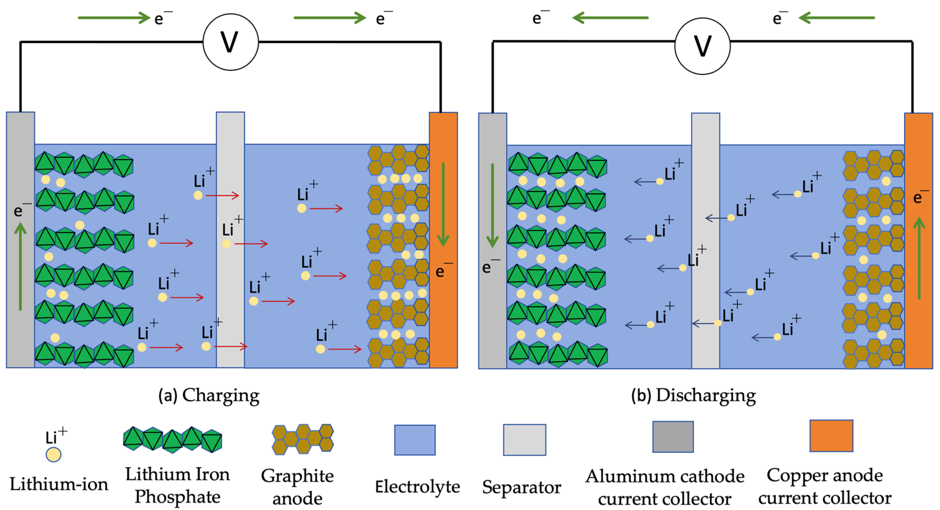
Figure 3.
(a) Longitudinal section of a commercial lithium-ion cell, and (b) illustration of the pseudo-two-dimension electrochemical model [10].
Figure 3.
(a) Longitudinal section of a commercial lithium-ion cell, and (b) illustration of the pseudo-two-dimension electrochemical model [10].
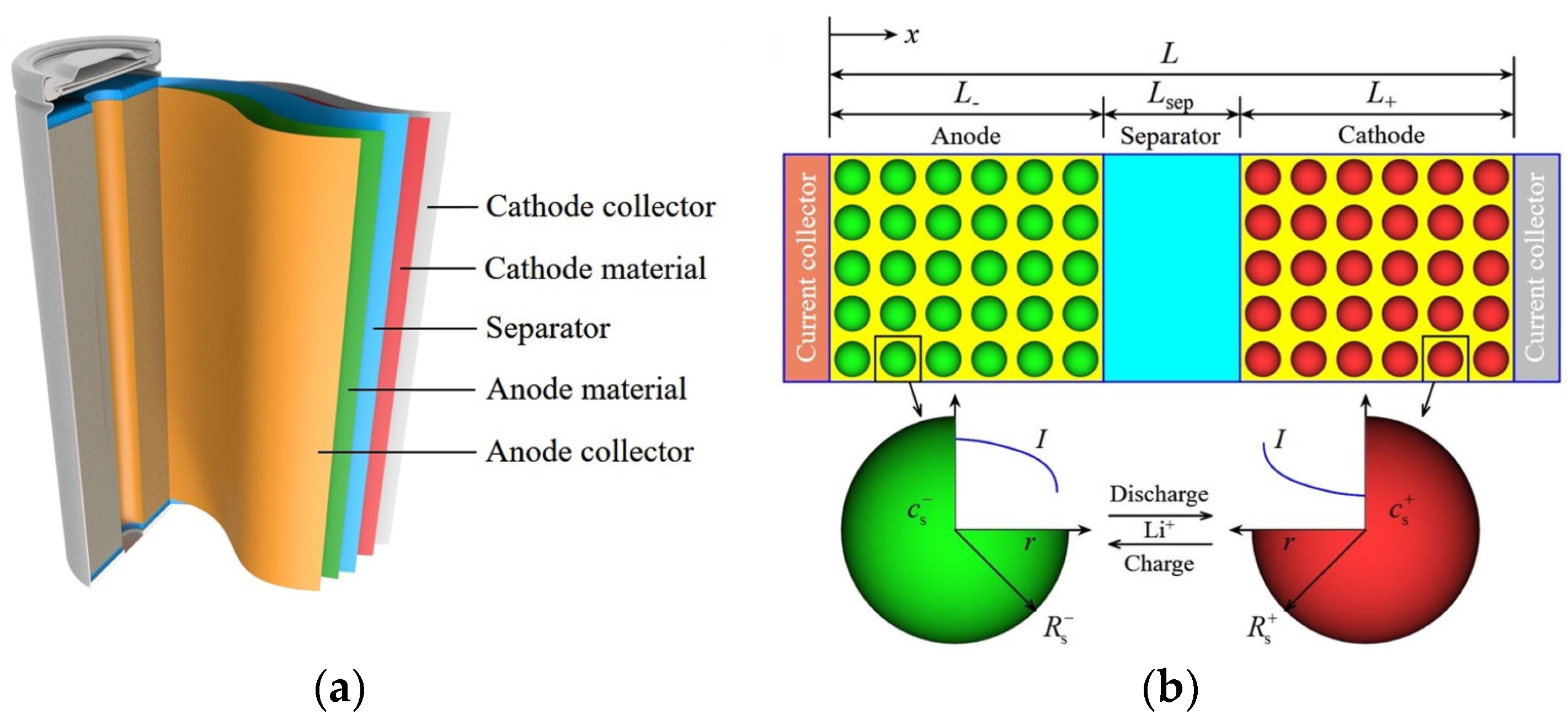
Figure 4.
Schematic diagram of (a) battery thermal model and (b) battery electrical model [16].
Figure 4.
Schematic diagram of (a) battery thermal model and (b) battery electrical model [16].
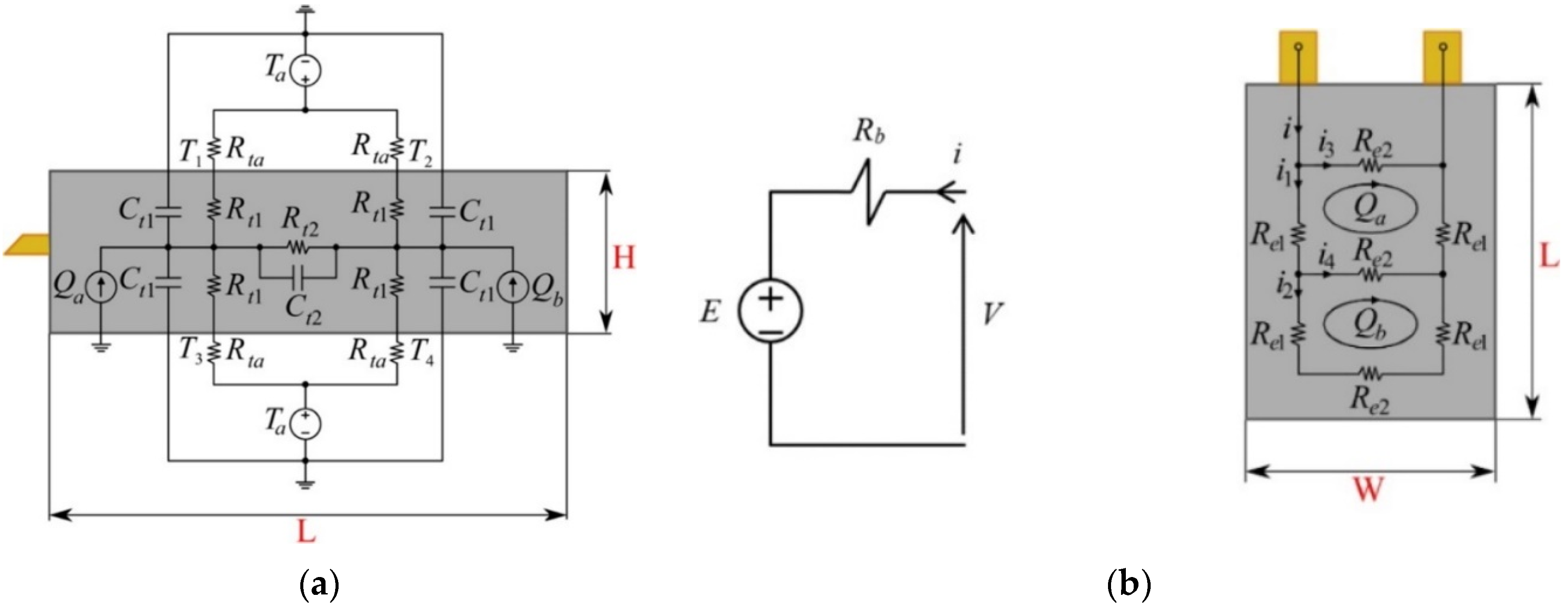
Figure 5.
Coordinate system and layered structure of the prismatic battery [14].
Figure 5.
Coordinate system and layered structure of the prismatic battery [14].
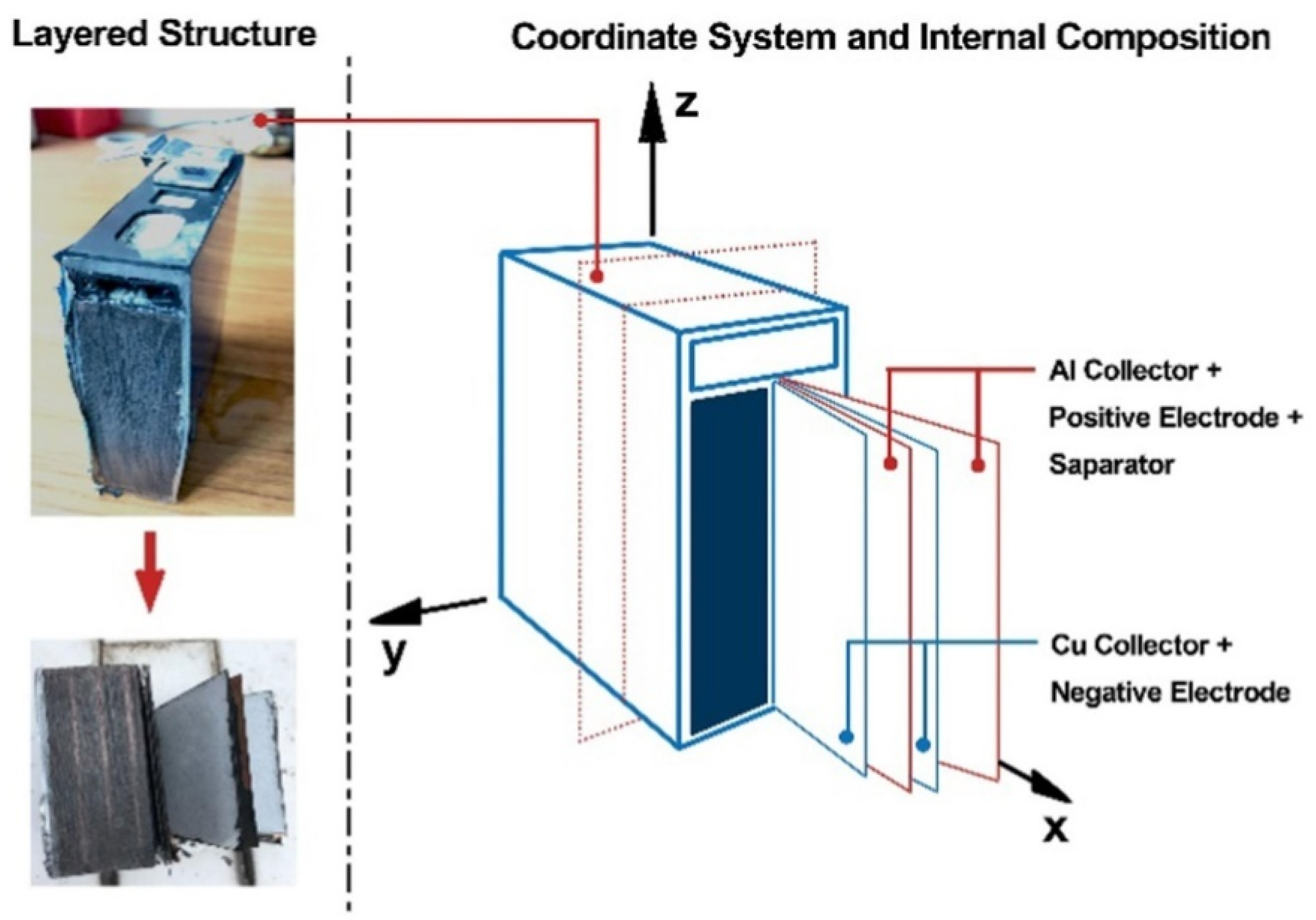
Figure 6.
(a) Schematic diagram of the experimental setup, and (b) comparison cycle life performance [38].
Figure 6.
(a) Schematic diagram of the experimental setup, and (b) comparison cycle life performance [38].
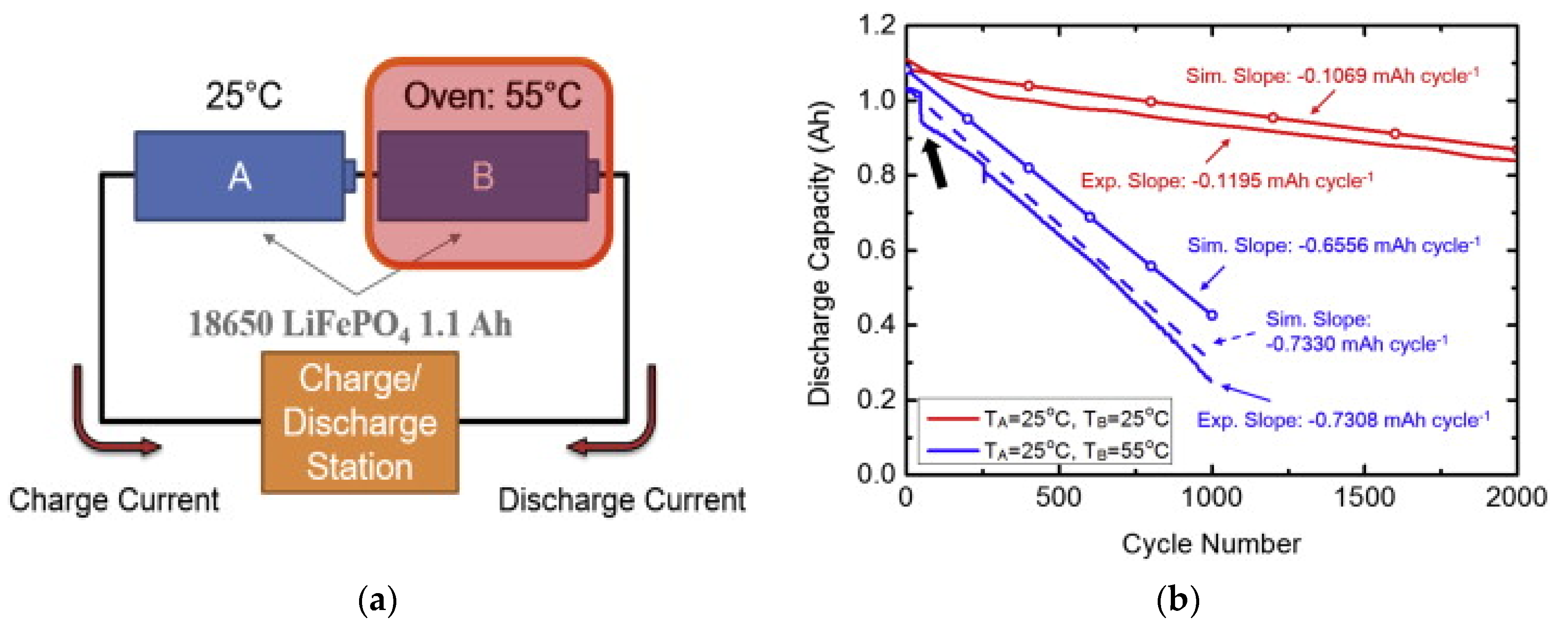
Figure 7.
Schematic diagram of air cooling, (a) passive air cooling, and (b) active air cooling [41].
Figure 7.
Schematic diagram of air cooling, (a) passive air cooling, and (b) active air cooling [41].
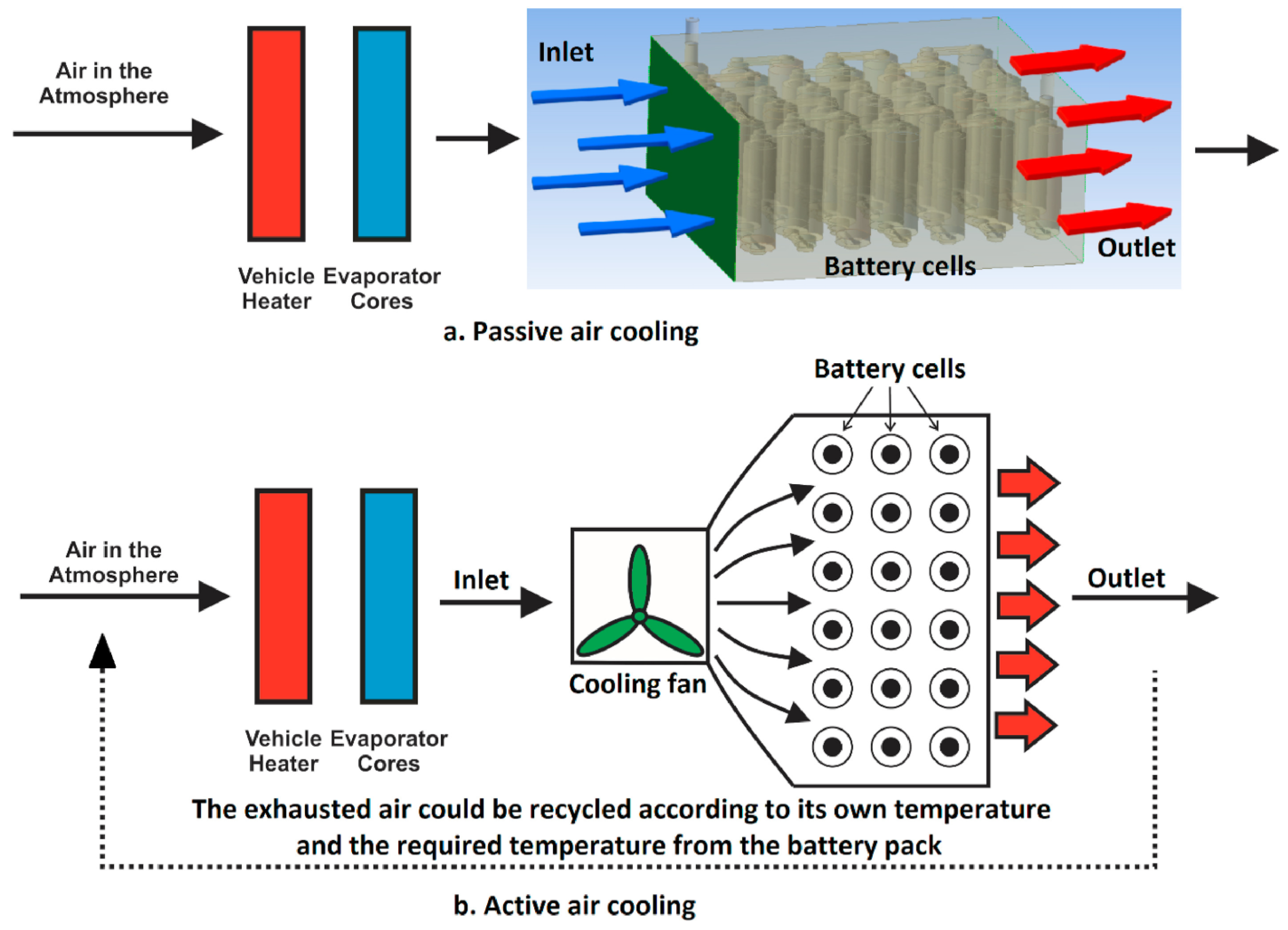
Figure 8.
Temperature distribution in the battery pack of (a) a square shape and (b) a rectangular shape at a full discharge point [48].
Figure 8.
Temperature distribution in the battery pack of (a) a square shape and (b) a rectangular shape at a full discharge point [48].

Figure 9.
The overall structure of tilting the battery pack casing [54].
Figure 9.
The overall structure of tilting the battery pack casing [54].

Figure 10.
The procedure of multi-objective evolutionary algorithm [56].
Figure 10.
The procedure of multi-objective evolutionary algorithm [56].
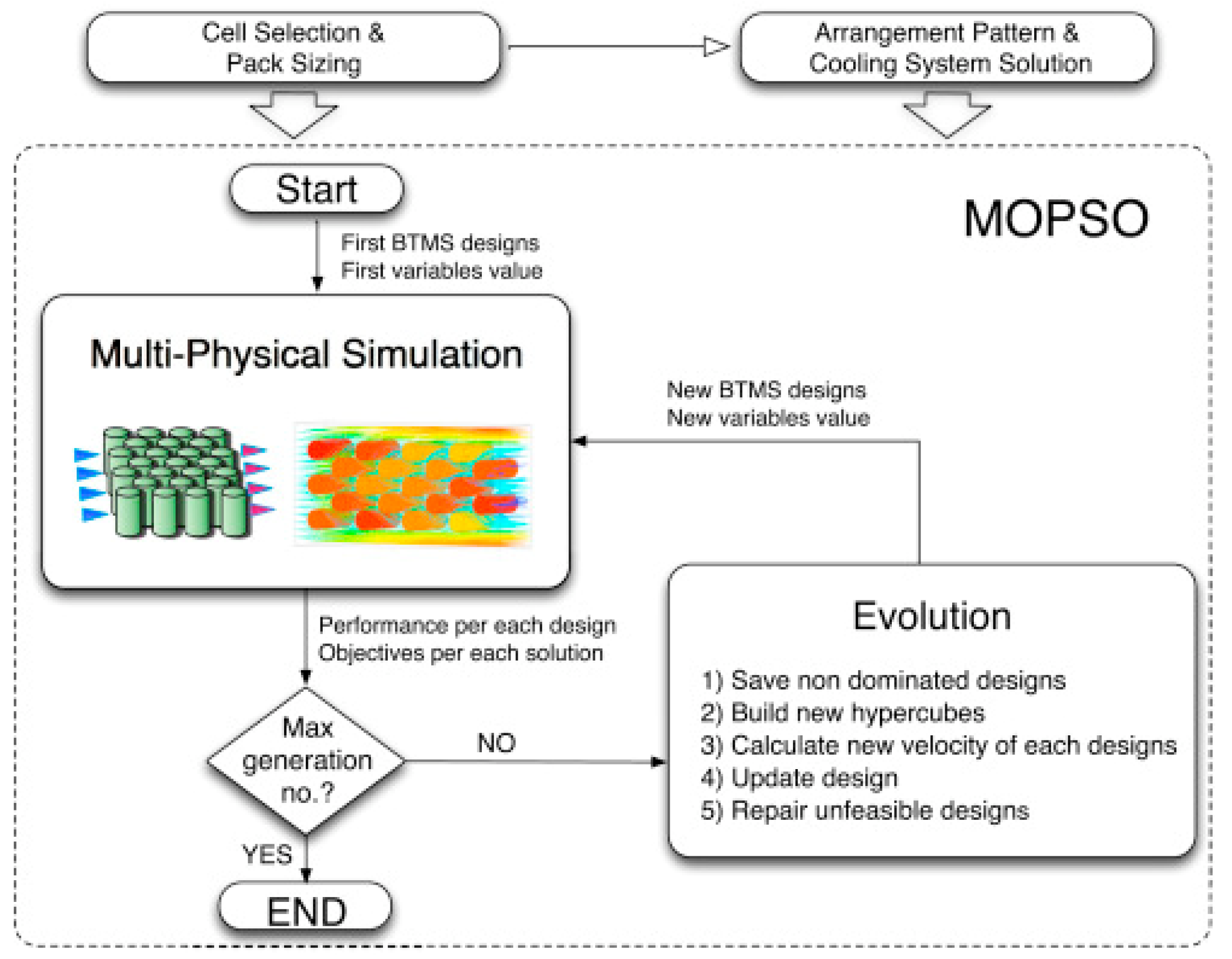
Figure 11.
The maximum temperature rise at the end of the discharge at a 2C discharge rate with different arrangements: (a) aligned, (b) staggered, (c) cross, and (d) schematic diagrams [51].
Figure 11.
The maximum temperature rise at the end of the discharge at a 2C discharge rate with different arrangements: (a) aligned, (b) staggered, (c) cross, and (d) schematic diagrams [51].

Figure 12.
Schematic diagram of (a) U-shaped channels [58], (b) J-shaped channels [59], and (c) Z-shaped channels of the air [60].
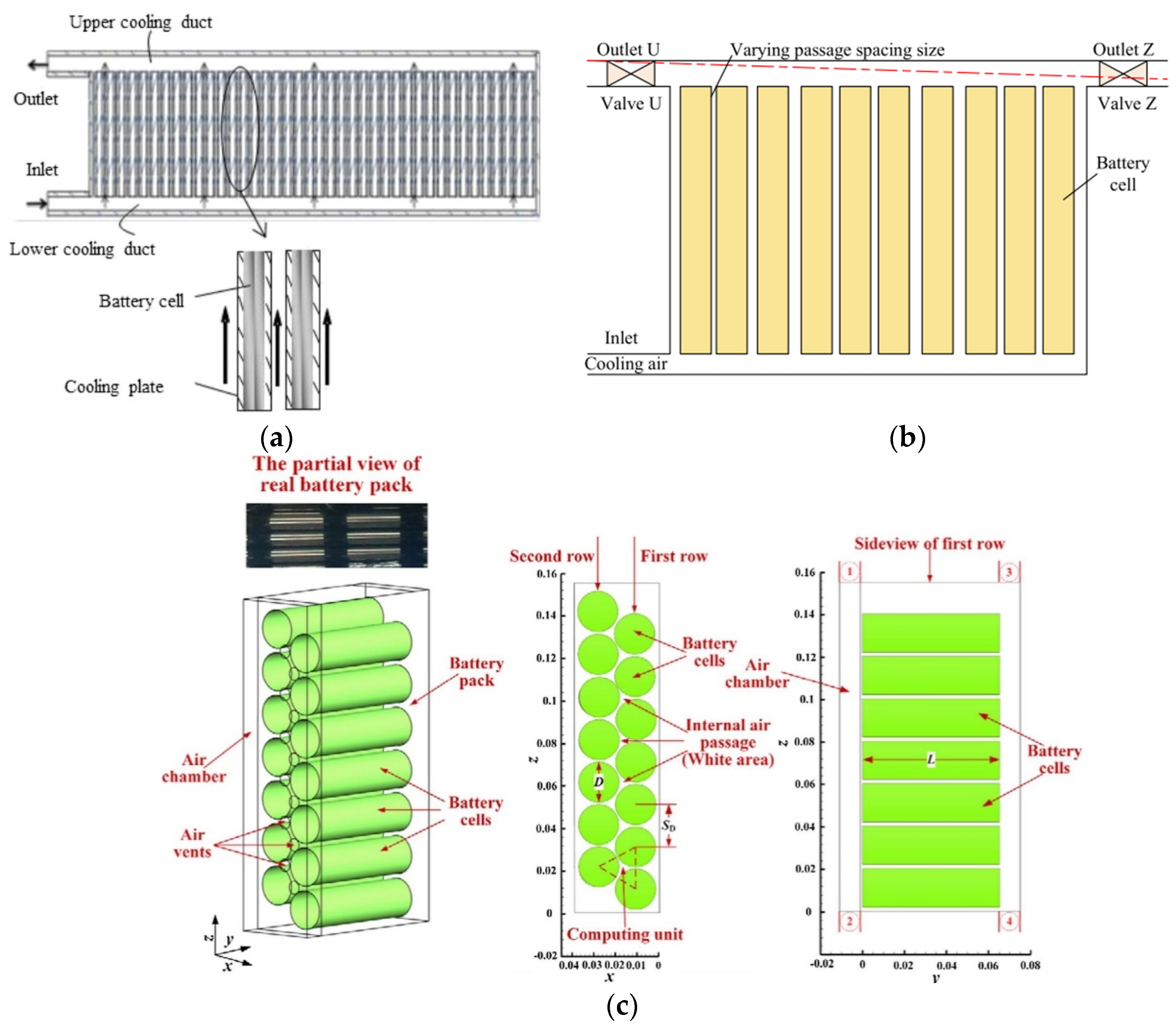
Figure 13.
Schematic diagram of reciprocating airflow design [64].
Figure 13.
Schematic diagram of reciprocating airflow design [64].

Figure 14.
Schematic and dimensions of the tested battery pack, (a) side view, (b) top view [72].
Figure 14.
Schematic and dimensions of the tested battery pack, (a) side view, (b) top view [72].
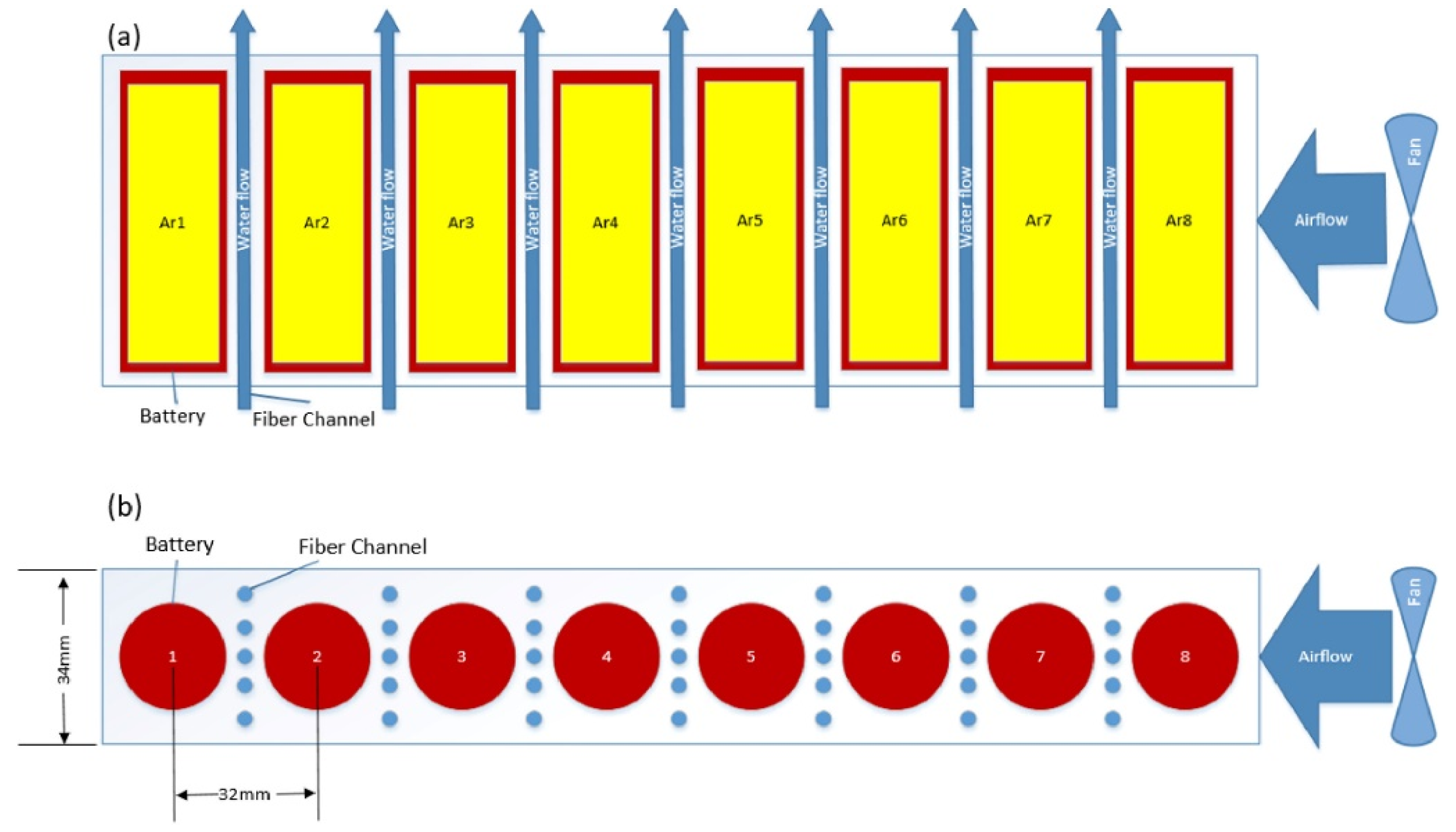
Figure 15.
Comparison among the three cooling types: no cooling, air cooling, and hybrid cooling, (a) average pack temperature, (b) temperature non-uniformity comparison [72].
Figure 15.
Comparison among the three cooling types: no cooling, air cooling, and hybrid cooling, (a) average pack temperature, (b) temperature non-uniformity comparison [72].
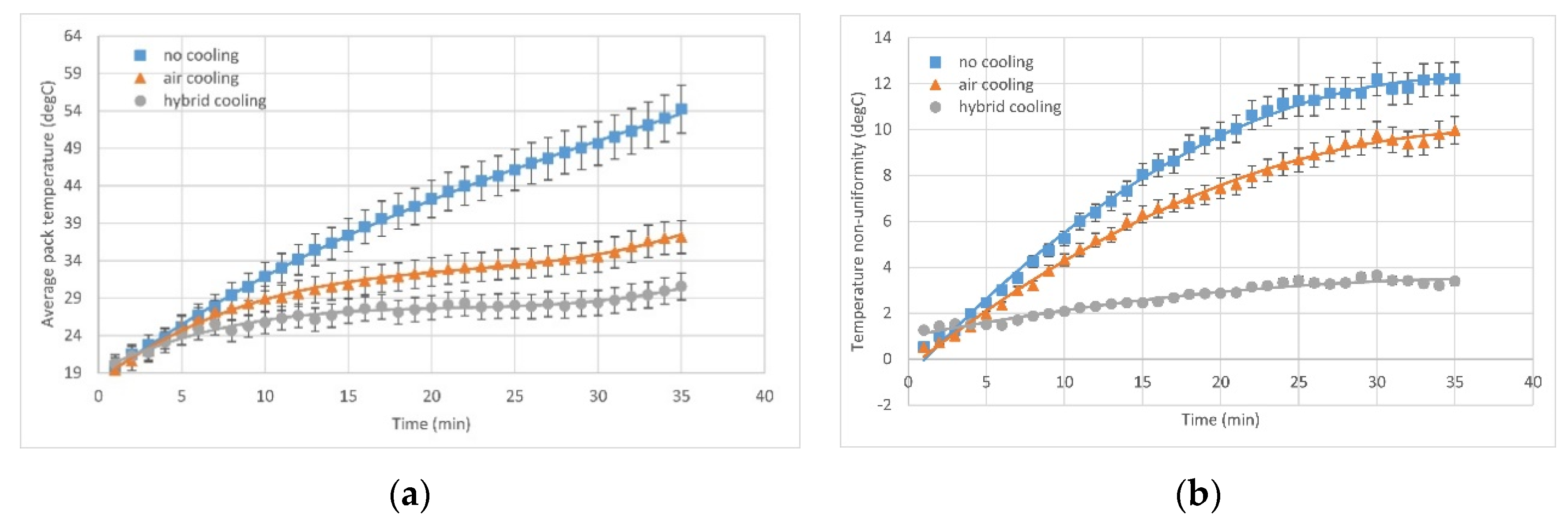
Figure 16.
Schematic diagram of aluminum foam heat sink [73].
Figure 16.
Schematic diagram of aluminum foam heat sink [73].

Figure 17.
(a,b) A sample of 10 PPI uncompressed aluminum foam [73].
Figure 17.
(a,b) A sample of 10 PPI uncompressed aluminum foam [73].

Figure 18.
Schematic diagram and temperature contours of indirect cooling: (a) tube sheets [82], (b) cooling plate [86].
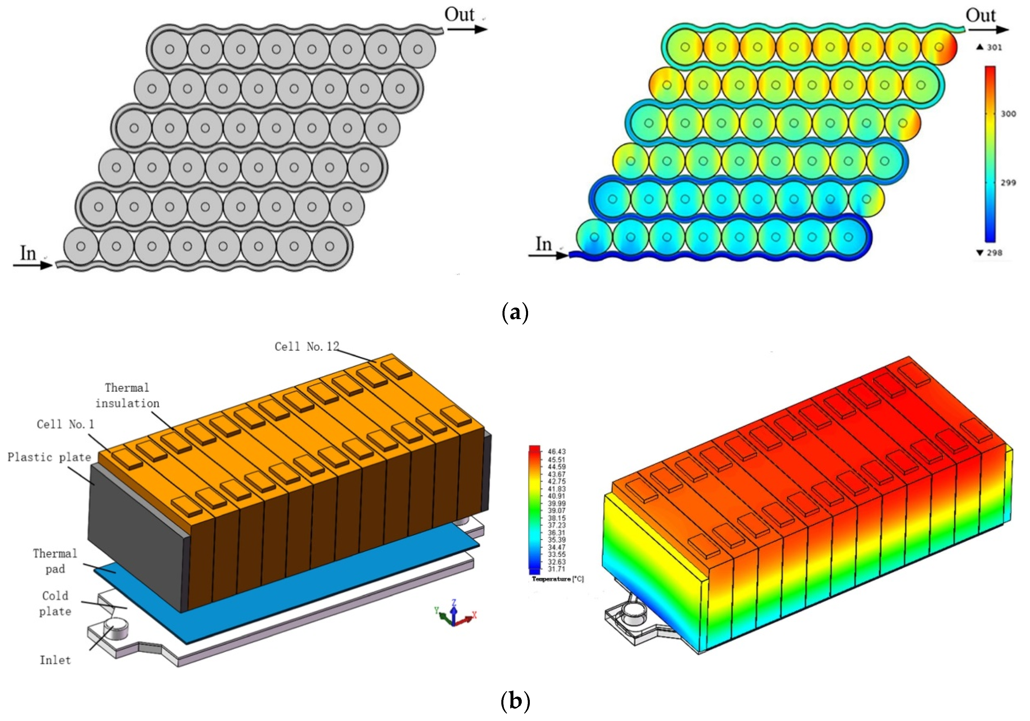
Figure 19.
Optimizing the structure of the cooling plate: (a) adding splitters [86], (b) serpentine-channel design [88].
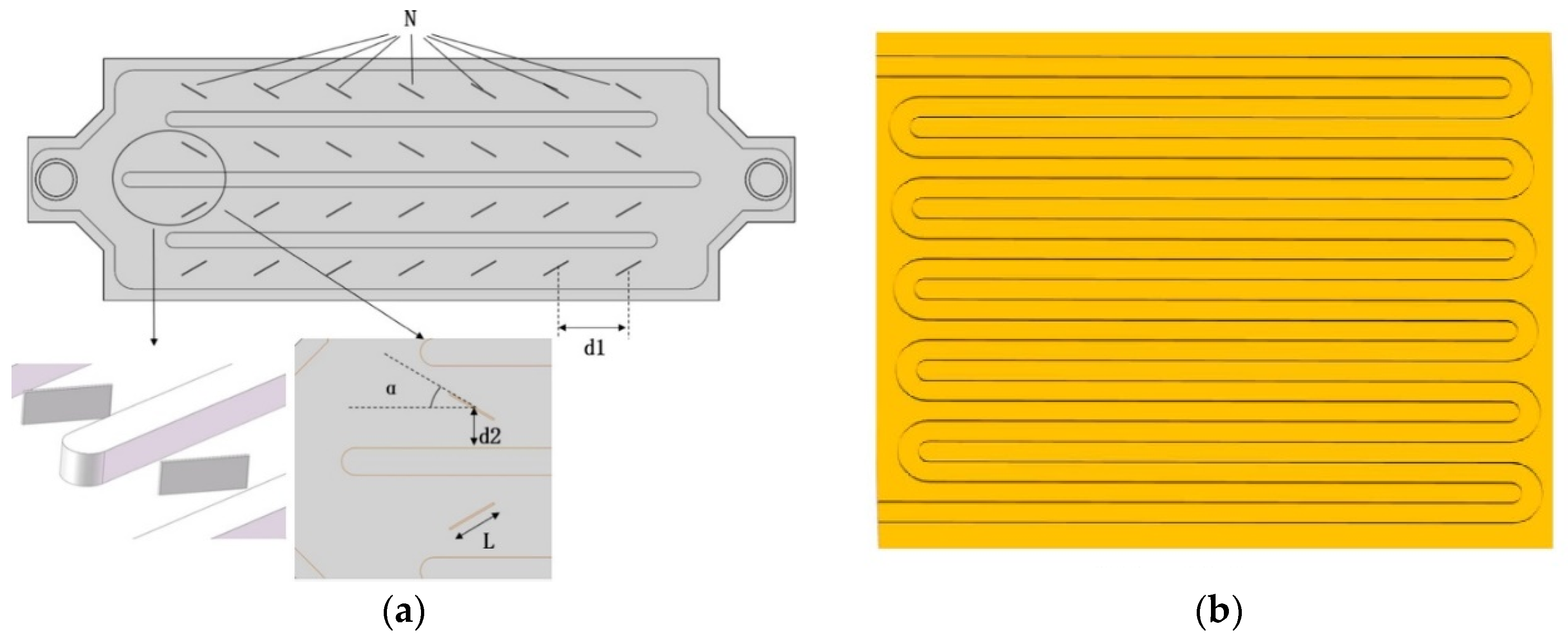
Figure 20.
Optimizing the structure of the tubes: (a) with cooper mold [96], (b) increasing the number of conductive pipes [97].

Figure 21.
Effect on (a) maximum temperature and (b) temperature difference of increasing AgO particles [96].
Figure 21.
Effect on (a) maximum temperature and (b) temperature difference of increasing AgO particles [96].
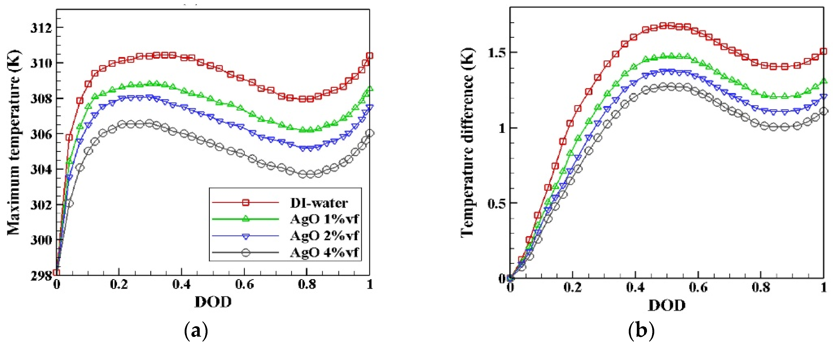
Figure 22.
A new scheme of delayed liquid cooling and the corresponding results [98].
Figure 22.
A new scheme of delayed liquid cooling and the corresponding results [98].

Figure 23.
Schemes of different immersion liquid BTMSs with (a) stationary coolant [104] and (b) flowing coolant [110].
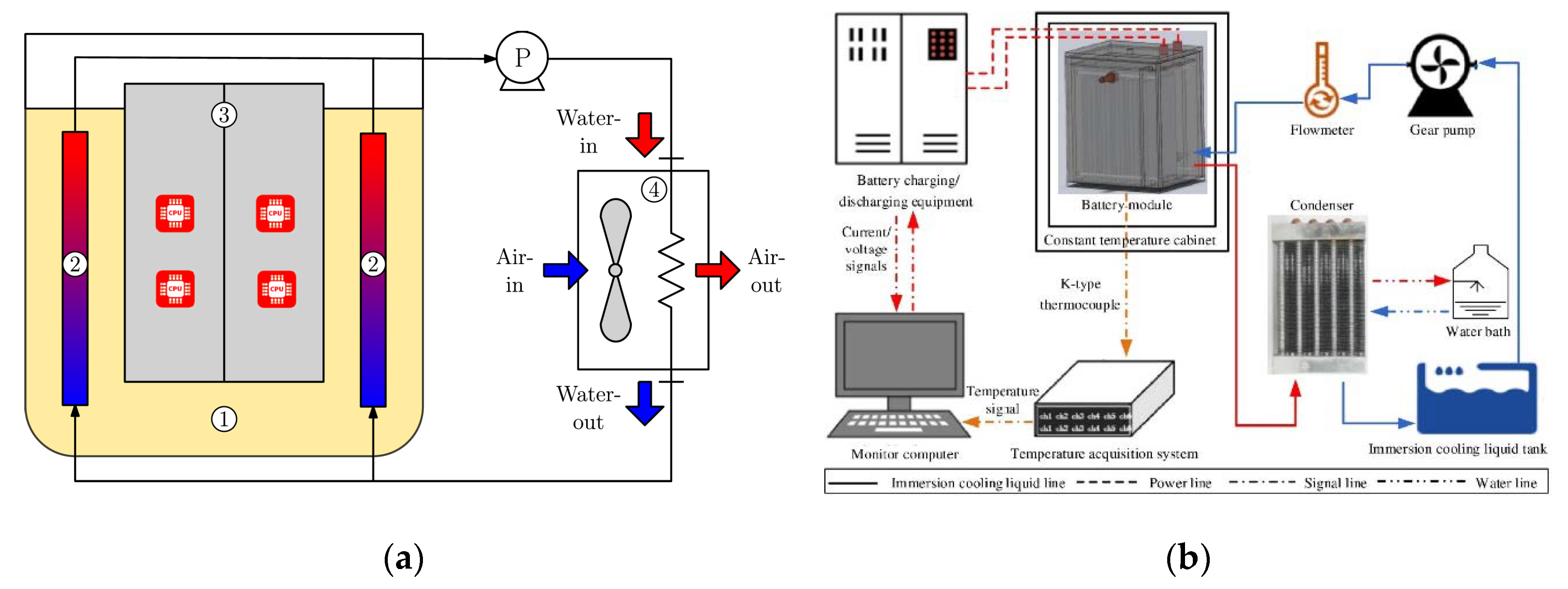
Figure 24.
Diagrams of (a) the DLC battery pack, (b) battery block, and (c) side views of the battery blocks with different flow channel configurations [117].
Figure 24.
Diagrams of (a) the DLC battery pack, (b) battery block, and (c) side views of the battery blocks with different flow channel configurations [117].
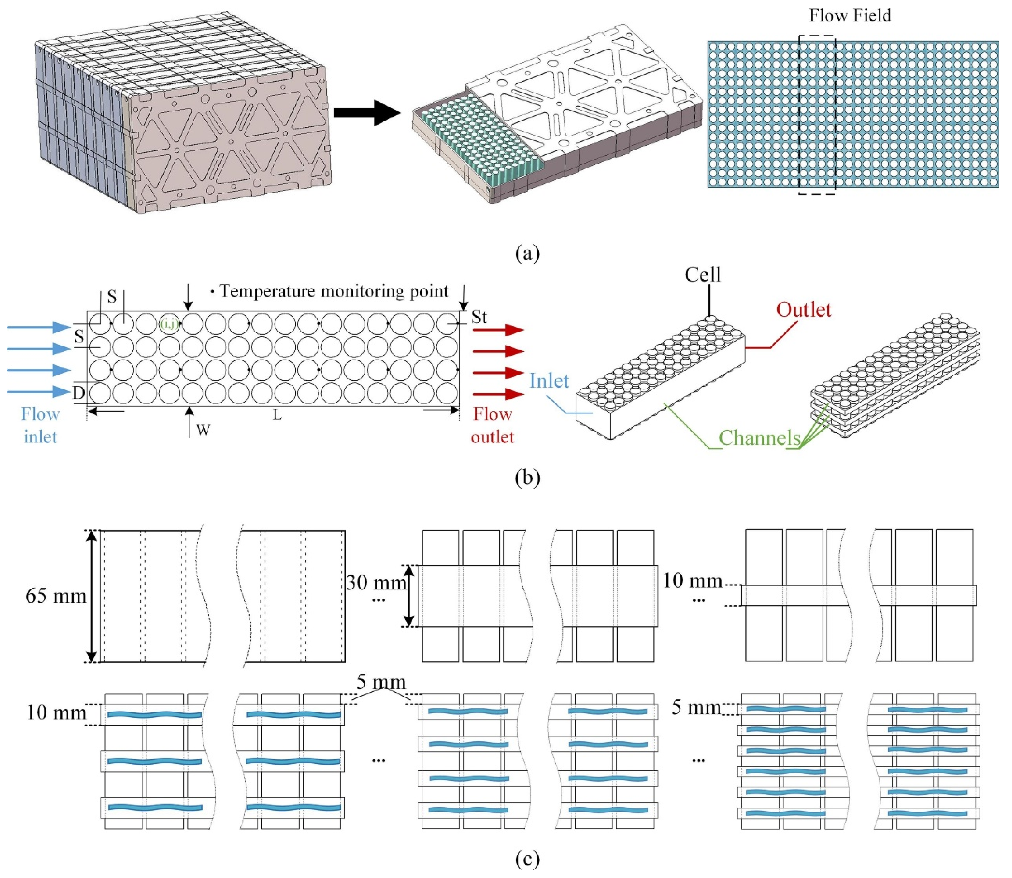
Figure 25.
Boiling curve of HFE-7000 within the battery module at 0.3 m/s [121].
Figure 25.
Boiling curve of HFE-7000 within the battery module at 0.3 m/s [121].
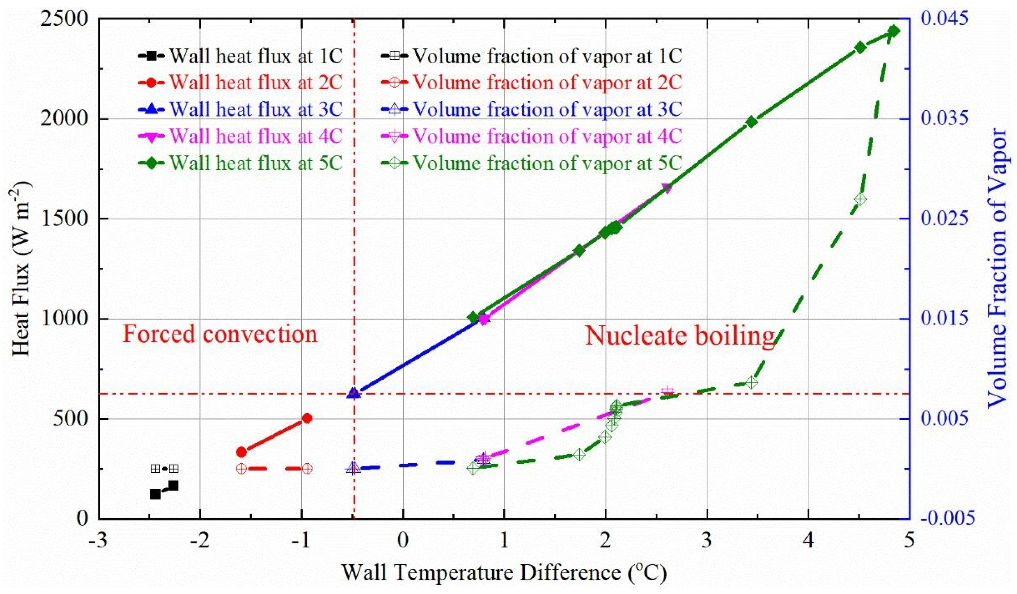
Figure 26.
Schematic diagram of direct two-phase refrigerant cooling [122].
Figure 26.
Schematic diagram of direct two-phase refrigerant cooling [122].

Figure 27.
PCMs BTMS concept.
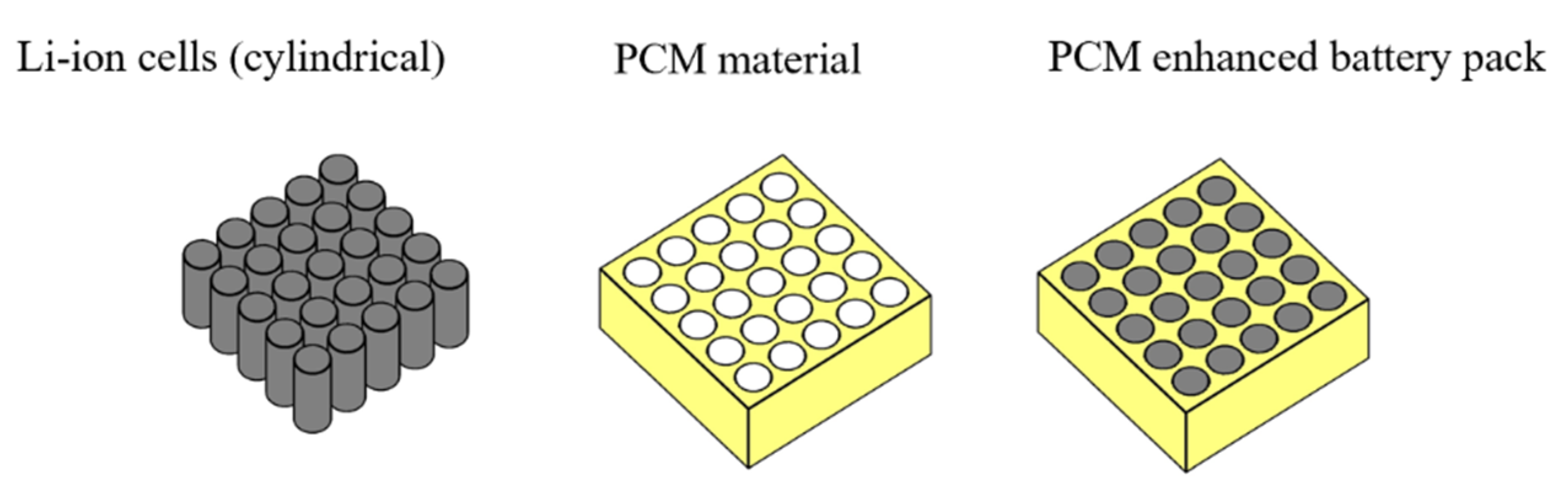
Figure 28.
Steps of preparation of the composite: (a) PCM/GNP, (b) PCM/carbon foam [140].
Figure 28.
Steps of preparation of the composite: (a) PCM/GNP, (b) PCM/carbon foam [140].
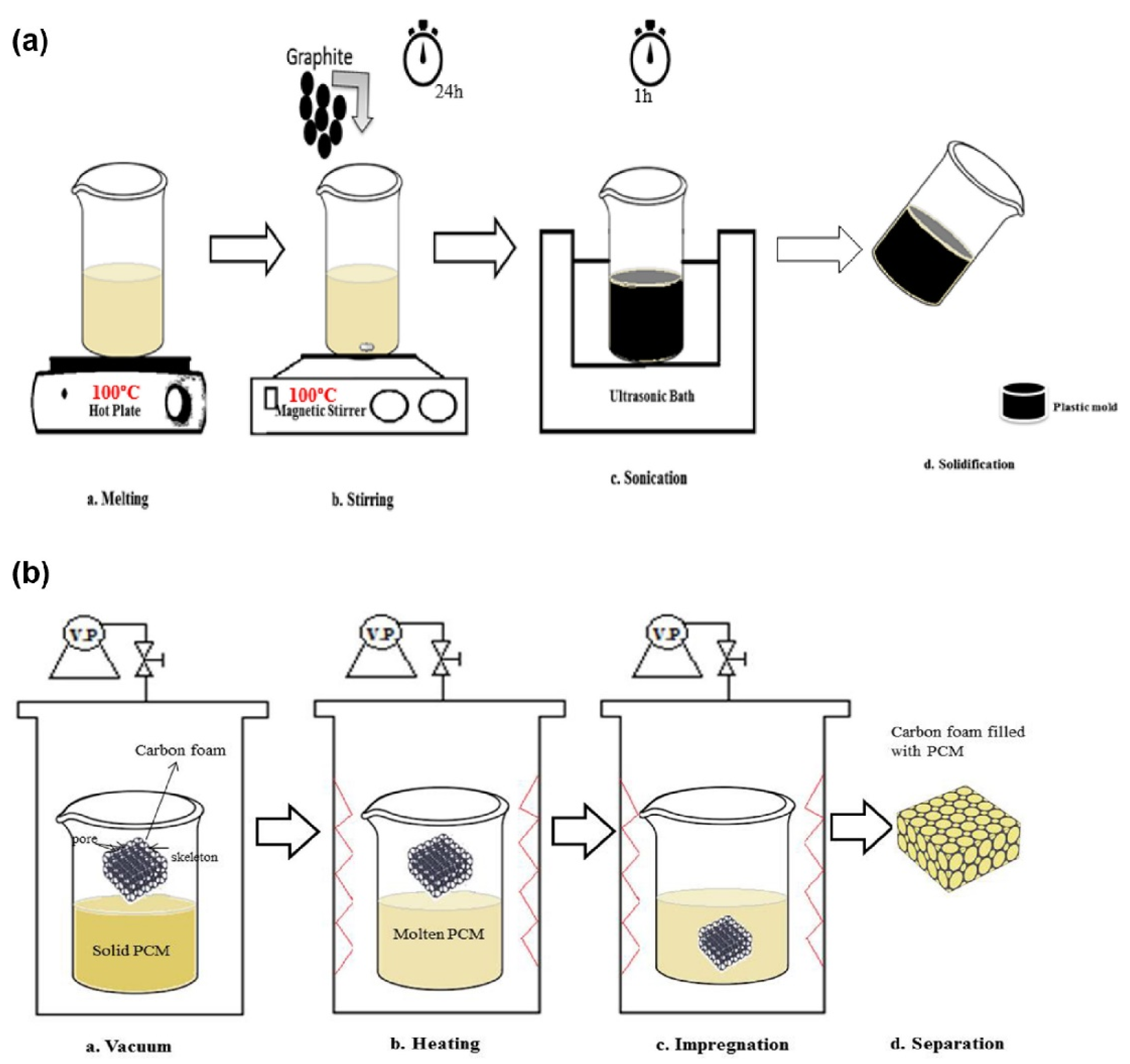
Figure 29.
Schematic diagram of the (a) PCM-based battery pack combined with air cooling, (b) experimental system [146].
Figure 29.
Schematic diagram of the (a) PCM-based battery pack combined with air cooling, (b) experimental system [146].

Figure 30.
Schematic diagram of PCM combined with a liquid cooling tube: (a) side view, (b) top view [99].
Figure 30.
Schematic diagram of PCM combined with a liquid cooling tube: (a) side view, (b) top view [99].

Figure 31.
Schematic of diagram of PCM combined with heat pipe: (a) details, (b) appearance [154].
Figure 31.
Schematic of diagram of PCM combined with heat pipe: (a) details, (b) appearance [154].

Figure 32.
Schematic diagram of the working principle of the heat pipe.
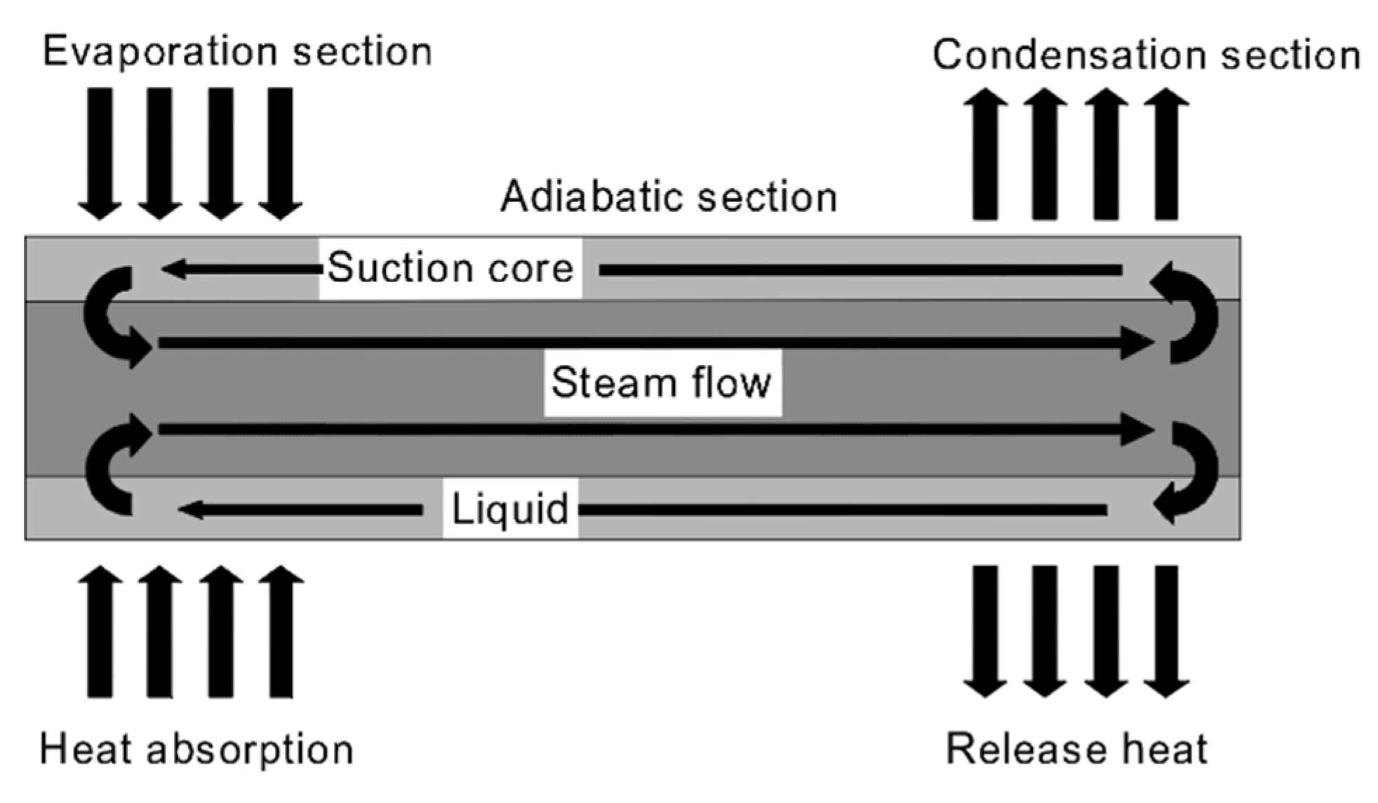
Figure 33.
Heat pipe-based battery thermal management system combined with liquid cooling [171].
Figure 33.
Heat pipe-based battery thermal management system combined with liquid cooling [171].

Figure 34.
Different factors’ effects on the range value of (a) maximum temperature and (b) temperature difference [168].
Figure 34.
Different factors’ effects on the range value of (a) maximum temperature and (b) temperature difference [168].
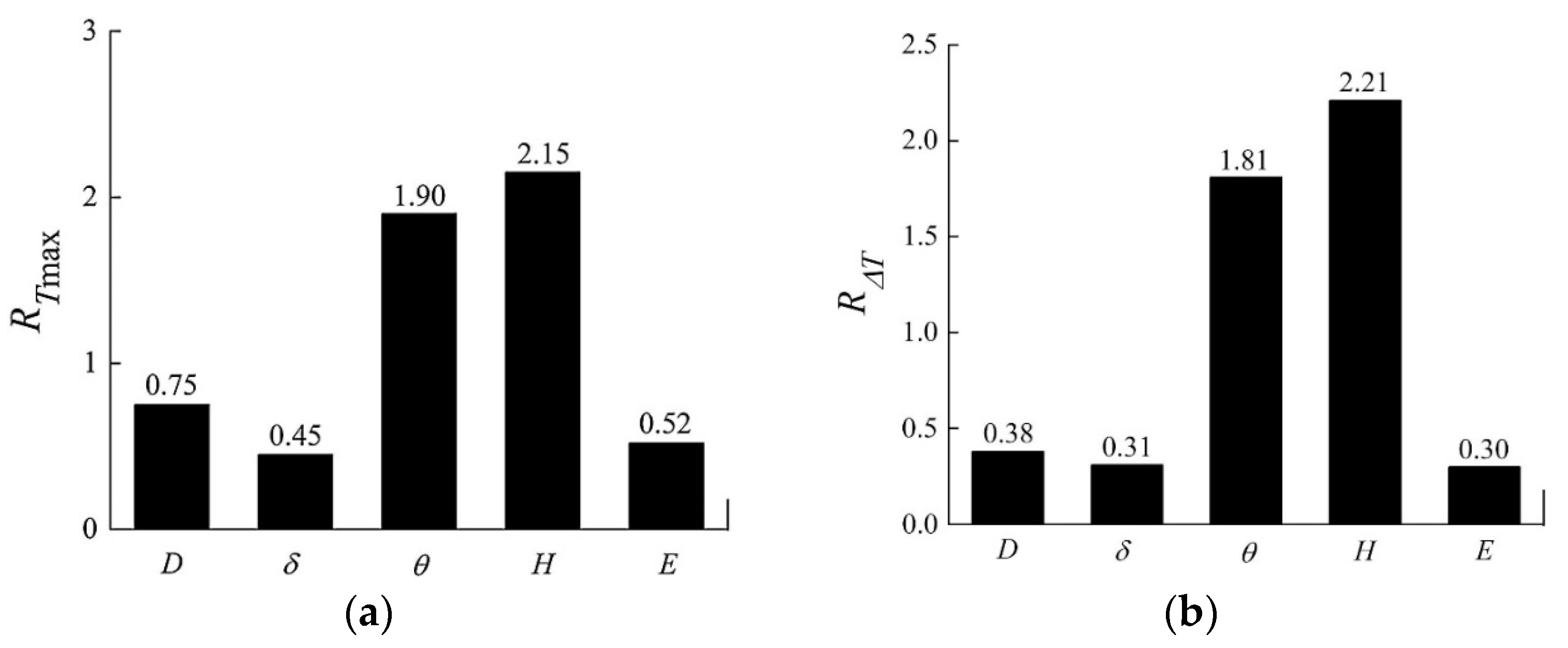
Figure 35.
Heat transfer and exchange process in a heat pipe combined with PCM [174].
Figure 35.
Heat transfer and exchange process in a heat pipe combined with PCM [174].
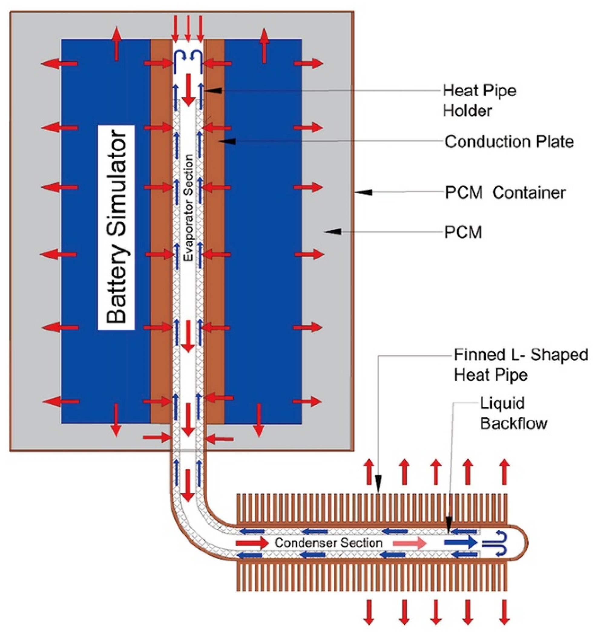

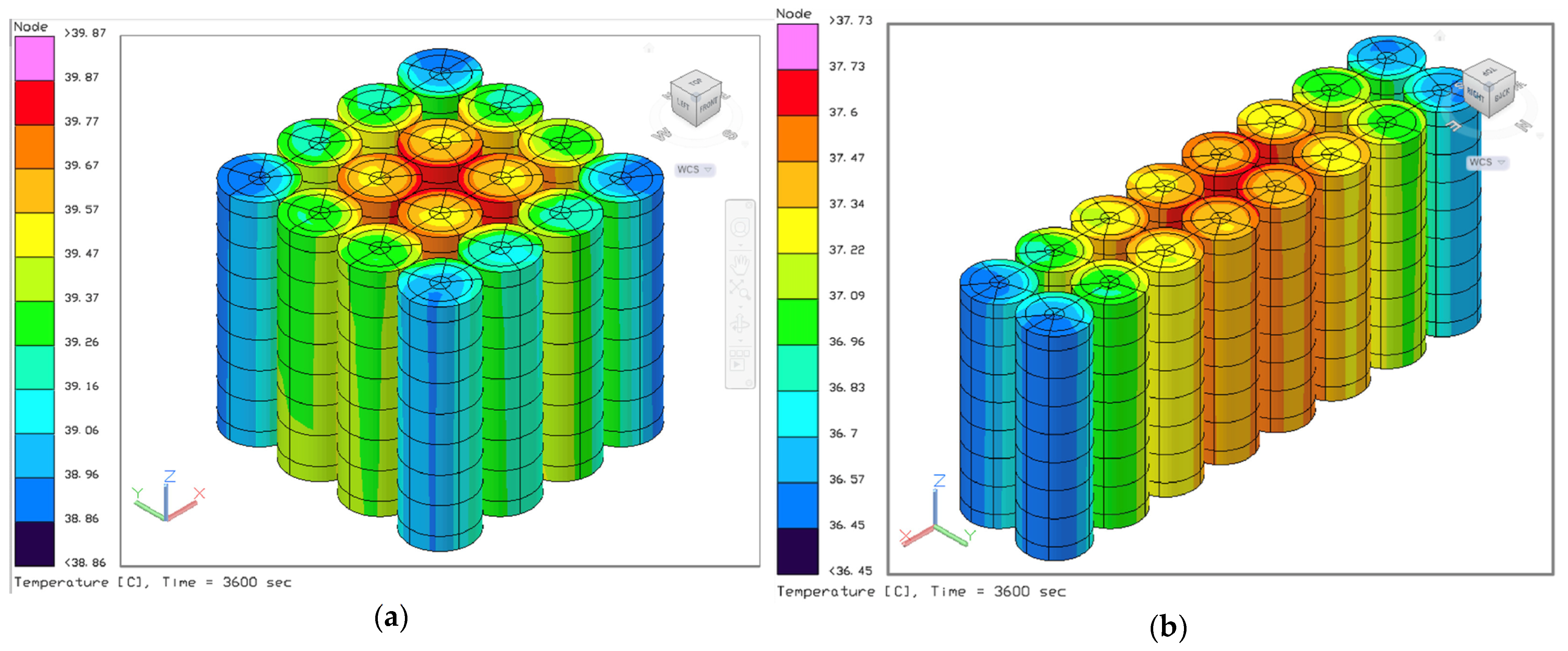
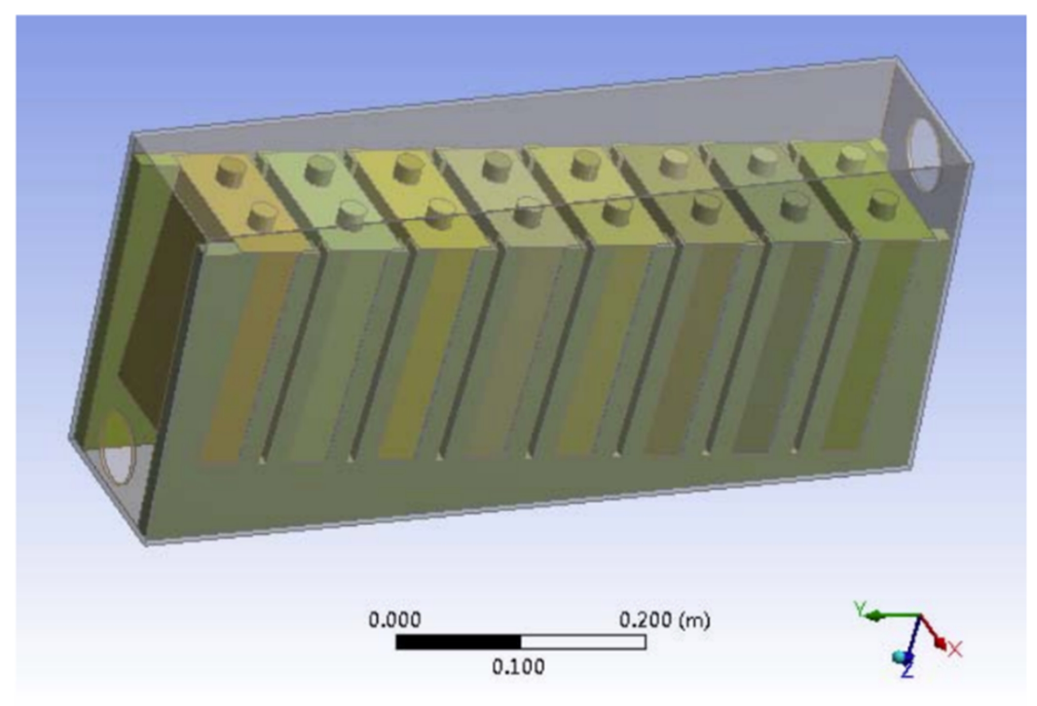
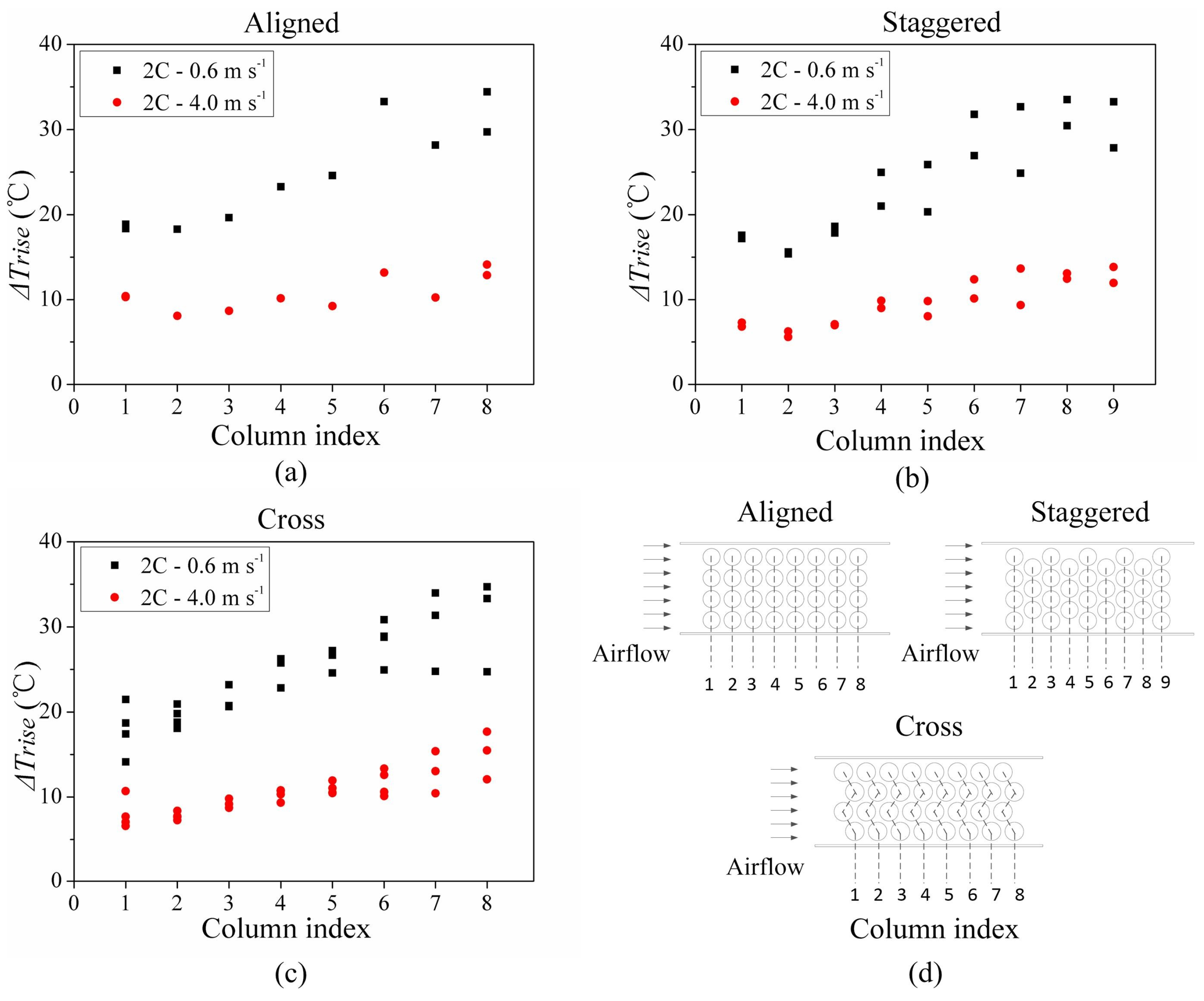
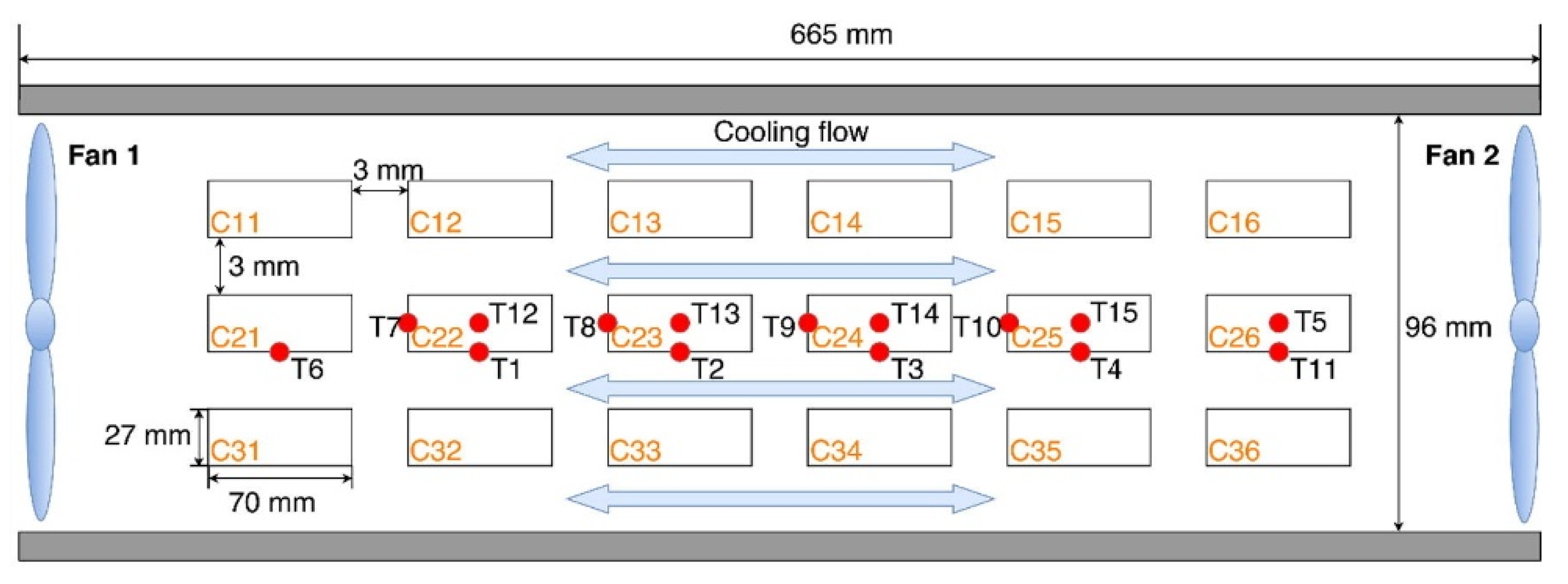
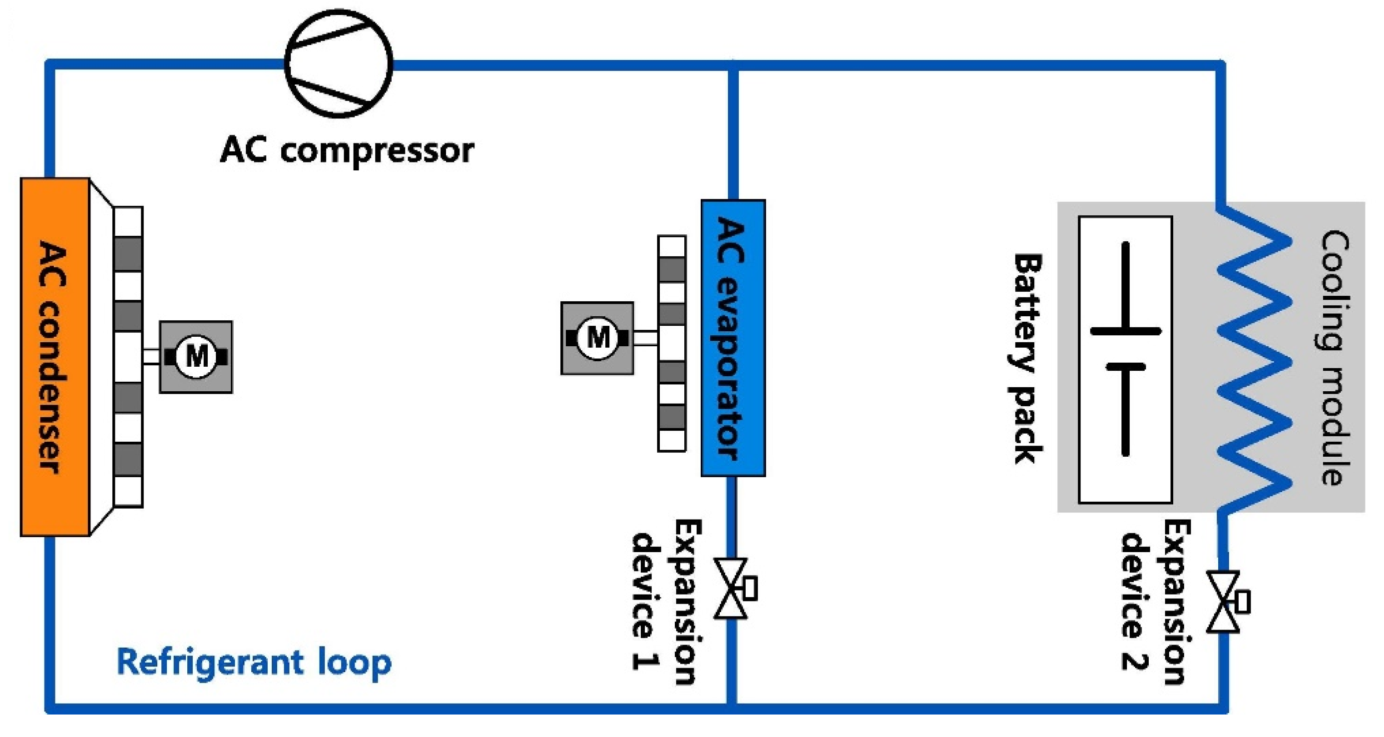
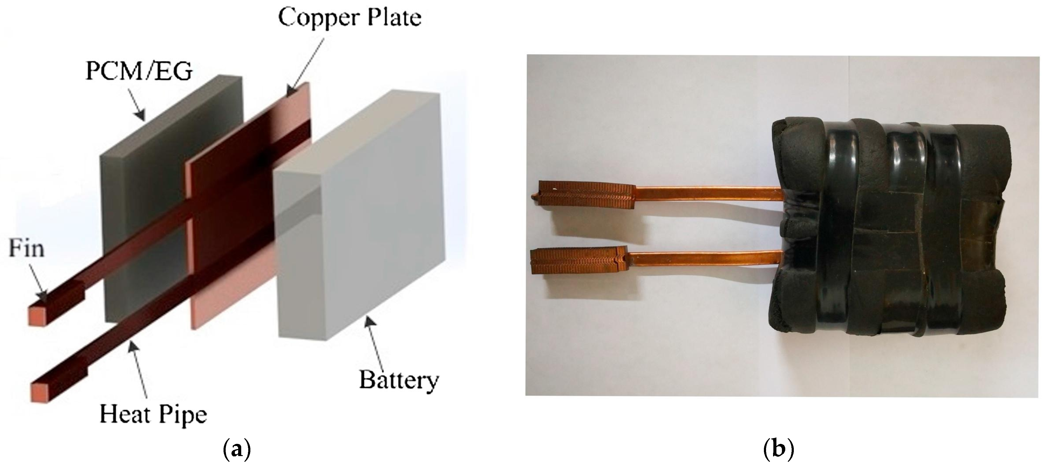
Table 1.
The comparison of advantages and disadvantages of different cooling systems.
| Thermal Conductivity | Uniform Temperature Distribution | Cost | Structure Complexity | Compactness | Weight | |
|---|---|---|---|---|---|---|
| Air cooling | Medium | Low | Low | Low | High | Low |
| Liquid cooling | High | Medium | Medium | Medium | Low | High |
| PCMs cooling | Low | High | High | High | Low | High |
Table 2.
Research on Immersion Liquid Cooling.
| Authors | Methods | Working Medium | Research Focuses | Conclusions |
|---|---|---|---|---|
| Wang et al. [110] | Experiment | No.10 transformer oil Single phase cooling | Different coolant depth, flow rate | When coolant depth and flow rate are increased, both maximum temperature and maximum temperature difference will be reduced. |
| Zhang et al. [111] | Experiment | Mineral oil Single phase cooling | Different oil immersion volume, flow rate, inlet, and outlet methods | With an increase in oil immersion volume and flow rate, and by changing positions of inlet and outlet, the battery thermal effect will be significantly improved. |
| Li et al. [112] | Experiment | SS/BN composite + water Single phase cooling | Different BN material ratios in SS | The composite material with 10wt% BN content should be the best choice for the battery surface coating material. |
| Al-Zareer et al. [113,114,115] | Simulation | R134a, Ammonia and Propane, Two phase cooling | Different liquid level | There is a positive correlation between the heat dissipation ability of the coolant and the liquid level of the coolant. |
| Park et al. [116] | Simulation | Mineral oil Single phase cooling | Different battery pack aspect ratios, battery spacing | A wider battery pack helps to improve temperature uniformity within the battery pack, while a narrower battery pack helps reduce system power consumption. |
| Tan et al. [117] (as show in Figure 24) | Simulation | HFE-6120 Single phase cooling | Different coolant channels, flow speeds, flow directions | With increasing height of the flow channel, maximum temperature, and maximum difference of temperature decrease, while power consumption increases with increasing flow rate. |
| Qin et al. [118] | Simulation | Dielectric fluid Single phase cooling | Different manifold structure in flow channel | Compared with separator thickness and outlet width, manifold channel width and battery spacing are two important factors. |
| Suresh Patil et al. [119] | Experiment + Simulation | Dielectric fluid Single phase cooling | Weather the coolant is flow, weather there is tabs | There is a 46.3% reduction in tab temperature of the battery thanks to the coolant flow and tab cooling aid. |
| Guo [120] | Experiment + Simulation | D-1 type electronic fluorinated fluid Single phase cooling | Different flow rate, battery design arrangements and overheated batteries | A minimum flow rate of 0.5L/min is recommended for the battery pack in order to achieve less than 5 °C temperature non-uniformity. |
| Wang et al. [121] (as show in Figure 25) | Experiment + Simulation | HFE-7000 Two-phase cooling | Different coolant inlet temperature, inlet flow rate | With a faster coolant flow rate, the battery pack maximum temperature will be lower; with a slower coolant flow rate, the temperature difference in the battery will be smaller and the battery will perform better. |
Table 3.
Differences between different types of heat pipes in power battery cooling [157].
Table 3.
Differences between different types of heat pipes in power battery cooling [157].
| Types | Advantages | Disadvantages |
|---|---|---|
| CHP | It is capable of fulfilling the heat dissipation needs of different electric fan configurations, while also having less stringent placement angle requirements. | There is a capillary limit. It is not suitable for high heat production conditions, and the cost is high. |
| GHP | According to the battery heat dissipation conditions, it is easy to process into the required structure, and the cost is low. | It is greatly affected by gravity and the placement angle is limited. Designing a heat dissipation system is difficult. |
| PHP | Due to the large equivalent heat transfer coefficient, the battery has a good antigravity performance and can effectively reduce the temperature rise. It also starts quickly. | The operating characteristics are complex. There are many factors affecting performance. Theoretical and application research is in the initial phase. |
| MGFHP | It can reduce the temperature difference between batteries and the weight of the heat dissipation structure, and it has good anti-gravity performance. | Due to insufficient capillary force, it is not suitable for high heat production conditions, and it is difficult to produce. |
| LHP | It is suitable for long-distance heat dissipation, the evaporation section and condensation section can be designed separately and is less affected by gravity. | It is not suitable for compact and distributed high heat flux cooling conditions, and it is difficult to start with low heat load. |
Disclaimer/Publisher’s Note: The statements, opinions and data contained in all publications are solely those of the individual author(s) and contributor(s) and not of MDPI and/or the editor(s). MDPI and/or the editor(s) disclaim responsibility for any injury to people or property resulting from any ideas, methods, instructions or products referred to in the content. |
© 2023 by the authors. Licensee MDPI, Basel, Switzerland. This article is an open access article distributed under the terms and conditions of the Creative Commons Attribution (CC BY) license (https://creativecommons.org/licenses/by/4.0/).
Share and Cite
MDPI and ACS Style
Fu, P.; Zhao, L.; Wang, X.; Sun, J.; Xin, Z. A Review of Cooling Technologies in Lithium-Ion Power Battery Thermal Management Systems for New Energy Vehicles. Processes 2023, 11, 3450. https://doi.org/10.3390/pr11123450
AMA Style
Fu P, Zhao L, Wang X, Sun J, Xin Z. A Review of Cooling Technologies in Lithium-Ion Power Battery Thermal Management Systems for New Energy Vehicles. Processes. 2023; 11(12):3450. https://doi.org/10.3390/pr11123450
Chicago/Turabian StyleFu, Ping, Lan Zhao, Xuguang Wang, Jian Sun, and Zhicheng Xin. 2023. "A Review of Cooling Technologies in Lithium-Ion Power Battery Thermal Management Systems for New Energy Vehicles" Processes 11, no. 12: 3450. https://doi.org/10.3390/pr11123450
Note that from the first issue of 2016, this journal uses article numbers instead of page numbers. See further details here.