
Structural Optimization of High-Pressure Polyethylene Cyclone Separator Based on Energy Efficiency Parameters

1
School of Chemical Engineering and Technology, Hebei University of Technology, Tianjin 300130, China
2
Beijing Yanhua Engineering Construction Company, Beijing 102502, China
*
Author to whom correspondence should be addressed.
Processes 2023, 11(3), 691; https://doi.org/10.3390/pr11030691
Submission received: 7 February 2023
/
Revised: 18 February 2023
/
Accepted: 20 February 2023
/
Published: 24 February 2023
(This article belongs to the Special Issue Smart Manufacturing & Automation Control Systems for Industry 4.0/5.0)
Abstract
:The high-pressure polyethylene process uses cyclone separators to separate ethylene gas, polyethylene, and its oligomers. The oligomers larger than 10 microns that cannot be separated must be filtered through a filter to prevent them from entering the compressor and affecting its normal operation. When the separation efficiency of the cyclone separator is low, the filter must be cleaned more frequently, which will reduce production efficiency. Research shows that improving the separation efficiency of the separator is beneficial for the separation of small-particle oligomers and reduces the frequency of filter cleaning. For this reason, Computational Fluid Dynamics simulations were performed for 27 sets of cyclone separators to determine the effects of eight structural factors (cylinder diameter, cylinder height, cone diameter, cone height, guide vane height, guide vane angle, exhaust pipe extension length, and umbrella structure height) on separation efficiency and pressure drop. The equations for separation efficiency and pressure drop using these eight factors and the equations based on energy-efficiency parameters were determined. The optimization analysis showed that separation efficiency can be improved by 98.7% under the premise that the pressure drop is only increased by 8.2%. By applying the improved structure to the high-pressure polyethylene process, separation efficiency is increased by 17.7%, which could effectively reduce the frequency of filter cleaning for this process, and thereby greatly improve production efficiency.
1. Introduction
In the production of high-pressure polyethylene, the main processes are divided into ethylene compression, polymerization, separation, granulation, mixing and air delivery, processing, packaging and palletizing, and other processes. The corresponding process flow is shown in Figure 1. The conversion rate of ethylene is about 20%. After the ethylene is compressed and polymerized, the polyethylene/ethylene needs to be separated. The mixture enters the high-pressure and low-pressure separation systems, and the separated polyethylene is made into products after granulation, mixing, air delivery, processing, and packaging and palletizing. The ethylene obtained from the high-pressure separation process is mixed and filtered with fresh ethylene and then enters the secondary compressor of the compression system for recycling.
The process of the high-pressure separation system is shown in Figure 1. The polyethylene/ethylene mixture from the reactor is first separated from the polyethylene product via separator A, the oligomer enters the high-pressure primary separators B and C, and then it enters the secondary separation coolers E1~4 and separators D1~4 in turn with the ethylene. The separation process is divided into three stages. First, the mixture enters separator A through the a at 29 MPa and 230 °C to separate the polyethylene from the unreacted ethylene. By this means, 91 to 94% of the polyethylene can be separated. The separated polyethylene enters the low-pressure separation system through the n. The unseparated oligomers are entrained in the form of mist entrainment or a homogeneous phase through b and c in series to the high-pressure primary separators B and C, which separate the larger oligomers. Subsequently, the fine oligomers that cannot be separated enter the coolers E1~4 and separators D1~4 in series in the order of d→E1→e→D1→f→E2→g→D2→h→E3→i→D3→j→E4→k→D4 for cooling and separation, in which some homogeneous substances will change into two-phase states of gas and liquid phases in the coolers when the temperature decreases, which will be separated in the separators. The oligomers separated in separators B, C, and D1~4 are stored in the discharge tank after o, p, q, r, s and t. The final oligomers that fail to be separated will be filtered through l in the mixing filter F to remove oligomers of 10 microns and larger to prevent larger oligomer particles from entering the secondary compressor and causing damage. The filter needs to be cleaned regularly, and when the separation efficiency of the separator is low, the frequency of filter cleaning increases, which is very inconvenient for the ultra-high-pressure production device. For this reason, it is necessary to improve the separation efficiency of the separation system. Research shows that droplets with a large particle size are easy to separate in gas-liquid separation, while droplets with a small particle size are difficult to separate [1,2,3]. Therefore, separators D1~4 are the key to the separation of small-particle oligomers.
The D1~4 separators each use cyclone separators, a kind of centrifugal separator, which use the centrifugal force field generated by strong cyclones to achieve relative movement of mixed materials with different densities to achieve the purpose of gas-liquid separation. This system is advantageous due to its compact structure, low volume capacity, low cost, and ability to cope with high temperature and high pressure [4,5,6].
The cyclone separator has no moving parts and its overall form is simple, but the internal flow field is very complex, and the dimensions between the various structures are very closely matched and mutually constrained. In recent decades, a great deal of experimental and theoretical research has been carried out in order to make cyclones smaller and more compact in size, more efficient in separating materials, and more energy-efficient [7,8,9,10]. However, it is very difficult to test the efficiency of a high-pressure cyclone separator with a real cyclone separator model. Many scholars have struggled to derive a suitable mathematical model to study and predict the flow behavior and to find a suitable cyclone geometry. Therefore, due to the complexity of cyclone separators, no accurate mathematical model of the cyclone separator has been proposed yet. Computational Fluid Dynamics (CFD), as an effective numerical method for calculating complex flow, has been widely used in the study of cyclone separators [11]. In recent years, scholars have conducted a large number of studies on various cyclonic separators using CFD [12,13,14,15,16,17,18]. In CFD, the selection of the turbulence model is very important. For the calculation of swirling flow, the existing turbulence models used are mainly the standard k-ε model, RNG k-ε model, Reynolds Stress Model (RSM), and Large Eddy Simulation (LES)—and only the RSM and LES can simulate the main characteristics of highly complex vortex flow in the swirling flow field. Many scholars have studied which turbulence model is most suitable for cyclone separators [14,19]. Among various turbulence models, RSM is the best model for predicting airflow turbulence and simulating the flow pattern inside the cyclone separator [20,21,22] because it ignores the assumption of isotropic flow. The results from this turbulence model were in good agreement with the experimental data [23].
The main evaluation indices of cyclone separator performance are separation efficiency and pressure drop [24]. Separation efficiency directly determines productivity and is the first indicator used to evaluate performance; pressure drop is an indicator used to evaluate the energy dissipation rate of the cyclone separator. When the pressure of the gas flowing from the inlet to the outlet of the cyclone separator decreases, pressure drop occurs in the cyclone separator. The reason for this pressure drop is that when the mixture hits or makes contact with the guide vanes, walls, and other components of the cyclone separator, the pressure decreases due to friction and resistance. The geometry of the cyclone separator has a significant effect on its performance. Various scholars have studied the effect of geometric parameters on the performance of cyclone separators [5,25,26]. The results show that there are many secondary flows inside the cyclone separator, such as short-circuit flow, circulating flow, and back-mixing flow at the bottom of the straight pipe section [27,28]. In CFD simulations, Elsayed, K. and Lacor, C. found that changing the extension length of the exhaust pipe has a significant effect on the pressure drop and separation efficiency of the cyclone separator [29]. Hamdy, O. and Shastri, R. et al. discovered that the cone length and cone angle had a significant effect on the flow pattern inside the cyclone separator [30,31]. Misiulia, D. and Zhou, F. et al. found that spiral guide vanes also have a great influence on the velocity distribution, turbulence intensity, pressure drop, and collection efficiency of cyclone separators [32,33]. In the research of many scholars [34,35], new designs have been thoroughly studied by adjusting one parameter each time to optimize the cyclone separator’s geometric parameters, keeping all other parameters unchanged until the optimum working conditions are found. The industrial application of cyclone separators generally requires the simultaneous consideration of several factors, as well as the complexity of the flow field inside the cyclone separator and the interplay between various structural factors. Therefore, it is necessary to establish the restriction and coordination relationship between the structural dimensions in order to optimize the cyclone separator. Ficici, F. and Ari, V. have used the Taguchi method to optimize the preheater cyclone separator [36]. They optimized the swirl performance by changing four parameters: diameter, vortex probe length, velocity inlet, and particle concentration. Significant energy savings could be achieved through the modification of the preheater cyclone separator design. Safikhani, H. obtained the pressure drop and medium particle size of the cyclone separator via CFD calculation and then optimized the performance of the cyclone separator using a multi-objective optimization method with an artificial neural network to determine the objective function [37]. Sankar, P.S. and Prasad, K. used response surface methodology to optimize various geometric parameters of the Stairmand cyclone separator [38]. Mariani, F. et al. optimized the length and angle of the overflow pipe to improve separation efficiency [39]. Venkatesh, S. analyzed the particle size and pressure drop performance of the square cyclone separator by changing five important geometric parameters via the CFD method [40]. Many studies on cyclones have been conducted by Elsayed, K. and Lacor, S. [41,42,43,44], who performed a multi-objective optimization of cyclone performance with the adjoint method, using an artificial neural network and genetic algorithms to analyze the pressure drop, separation efficiency, and cut-off diameter. The results showed that the inlet velocity and various geometric dimensions have a significant effect on the flow pattern, collection efficiency, pressure drop, and acoustic noise of axial cyclones. The main body of a cyclone, the vortex finder diameter and its insertion length, the height of the conical segment, the cone tip diameter, the dipleg length, the dustbin height, and the dustbin diameter had significant effects on cyclone efficiency. Some experts have also studied other types of cyclone separators. Yao, X. et al. designed a gas-liquid cyclone separator with a simple structure, low pressure drop, and high separation efficiency to achieve efficient long-term separation of gas and liquid droplets [45]. He found that the vortex can be strengthened by changing the operating conditions and annular zone height, but inlet velocity does not impact vortex strength. The screw pitch is not affected by either inlet velocity or annular zone height. The total pressure drop is only weakly affected by the annular zone height but is obviously affected by the inlet velocity. Baltrėnas, P. and Chlebnikovas, A. designed a multi-channel cyclone separator to avoid the adhesion of sticky and moist solid particles on the inner surfaces of the cyclone by improving three structures (the secondary inlet, inner slit, and convex bottom) [46], which was effectively used in heat production equipment in private households. Zhou, W. et al. studied the effect of operating parameters such as inlet gas velocity and inlet liquid concentration on a gas-liquid cyclone separator in WGS [47], developed a model to predict the pressure drop, and also proposed an improved weighting method to calculate the droplet separation efficiency.
There are many studies on the optimization of cyclone separator geometries in the existing literature [48,49,50], but they are all related to the traditional cyclone separator. When using different fluid parameters and working spaces, the separator has different separation conditions and application scopes. In the context of the production of high-pressure polyethylene, the optimization of the high-pressure environment and high-density ethylene gas has not yet been studied. In high-pressure polyethylene production, the separation efficiency and pressure drop in the cyclone separator are important objective functions to be optimized simultaneously. For this, CFD simulations were carried out for separators D1~4 to solve the problem of small-particle droplets being difficult to separate, to find the main structural factors that affect separation efficiency and pressure drop, and to investigate the influence of the structural parameters of the cyclone separator on the separation efficiency in combination with the relevant process conditions, which can also reduce the frequency of cleaning required for the oligomer filter. In order to optimize the results more comprehensively, a dual-objective optimization study of performance parameters (separation efficiency and pressure drop) was carried out. The eight main size parameters of cyclone separators, cylinder section diameter, cylinder section length, cone section diameter, cone section height, guide vane height, guide vane angle, exhaust pipe extension length, and umbrella structure height, were analyzed using the Taguchi method. Fluent software was used to simulate the experimental combination model. The optimal combination of cyclone separator structures for the high-pressure polyethylene process, with respect to the eight dimensional parameters described, was determined based on energy-efficiency parameters using the unified objective function method. This will provide a feasible optimization method for the optimal design of cyclone separators. At the same time, it will have important research value for cyclone separators in high-pressure environments involving high-density gas phase media, and have important engineering application value for cyclone separators in the high-pressure polyethylene process.
2. Numerical Simulation
2.1. Cyclone Geometry
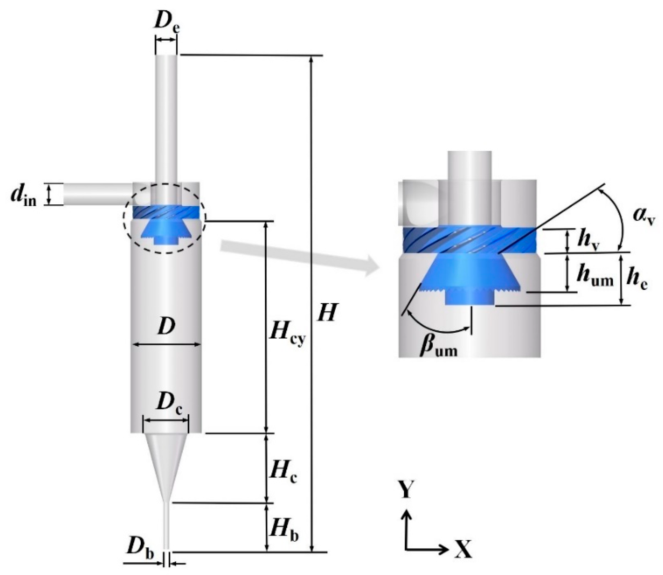
In the high-pressure polyethylene process, the cyclone separators B, C, and D1~4 have the same structural model. Their models are shown in Figure 2. The total height (H) of the cyclone separator is 1750 mm and the inner diameter is 250 mm. The main size parameters for the cyclone separator are listed in Table 1, which include the cylinder height (Hcy), cylinder diameter (D), cone height (Hc), cone diameter (Dc), inlet diameter (d), exhaust pipe diameter (De), bottom flow pipe diameter (Db) and height (Hb), guide vane height (hv) and angle (αv), exhaust pipe extension length (he), and umbrella structure angle (βum) and height (hum). The inlet pipe, guide vane, cylinder, cone, exhaust pipe, underflow pipe and umbrella structure are the main components of the cyclone separator.
2.2. The Governing Equations
It is assumed that the gas flow inside the cyclone is an incompressible isothermal flow. Therefore, according to the Reynolds-averaged Navier–Stokes (RANS) equations, the continuity equation of the averaged flow is as follows [51]:
The time-averaged Navier–Stokes equation is as follows [51]:
The last term is defined as the Reynolds stress tensor, which reflects the effect of turbulence intensity in the fluid flow. In the RSM, the transport equation is written as follows [48]:
The expression on the left side of the equation represents the convective transport term. The five terms on the right side of the equation are the diffusion term, yield term, pressure strain term, dissipation term, and source term. The final transport equation for the RSM can be written as follows [51]:
The eddy viscosity, μt, was calculated using the following equation:
where Cμ is 0.09.
2.3. Boundary Conditions
The inlet boundary condition was set as the inlet velocity. It is known that the volume flow rate of the gas-liquid mixture from separator B was 7.5 kg/s, the inlet velocity was 9.053 m/s, the mass concentration of the oligomers was 0.0033%, and the hydraulic diameter was 77 mm. The outlet boundary condition was set as the outlet pressure; the working pressure was 25 MPa and the atmospheric pressure was the standard atmospheric pressure. The inlet temperature was 200 °C. Since the fluid was gradually cooled, the density and viscosity of the gas phase gradually changed as the temperature decreased, but the oligomer was less affected, irrespective of changes in density and viscosity. In different cyclone separators, the corresponding calculation boundary conditions changed. The specific boundary conditions for each model are shown in Table 2.
Since the liquid phase only accounted for a very low volume fraction, the Euler–Lagrange method, based on the discrete phase model (DPM), was used to solve the time-averaged N–S equation with the fluid phase as the continuous phase and the liquid phase as the discrete phase. The wall flow boundary adopted the no-slip solid wall condition, and the standard wall function method was used to determine the flow near the solid wall [52]. This also assumed that there was no particle–particle interaction and that the flow field was bidirectionally coupled between the particles and the flow field [51,53]. To consider the effect of turbulent fluctuations on particles, the discrete random walk (DRW) model was used [20]. The inlet injection source for the droplet phase was a surface injection source with velocity consistent with that of the gas phase. Neglecting the aggregation and fragmentation caused by the collision between droplets, the outlet of the exhaust pipe was set as the escape condition, and the bottom outlet of the cyclone separator was set as the trap condition. Using the Rosin–Rammler distribution for the dispersed liquid phase, the inlet droplet size distribution from the filed feedback was used as the inlet boundary condition for the dispersed droplets, and the inlet of separator B obeyed the Rosin–Rammler droplet size distribution, as shown in Figure 3a. The inlet of separator D1 obeyed the Rosin–Rammler droplet size distribution, as shown in Figure 3b.
Using the commercial CFD software Fluent, the variables on the surface of the control body were interpolated using the second-order upwind format. The governing equations were solved numerically using the finite volume method. For pressure-velocity coupling, the Semi-Implicit Method for Pressure-Linked Equations Consistent (SIMPLEC) algorithm was used. Due to the highly rotating flow in the cyclone separator, the pressures were interpolated with the PREssure STaggered Option (PRESTO). In order to measure the flow in the cyclone separator, the Quadratic Upstream Interpolation for Convective Kinetics (QUICK) format of the momentum equation was used. The second-order upwind scheme was used to discretize the Reynolds stress equation. When the residual dropped below 10−4, the calculation was considered to be convergent. In this study, all of the simulations were performed using these discretization schemes.
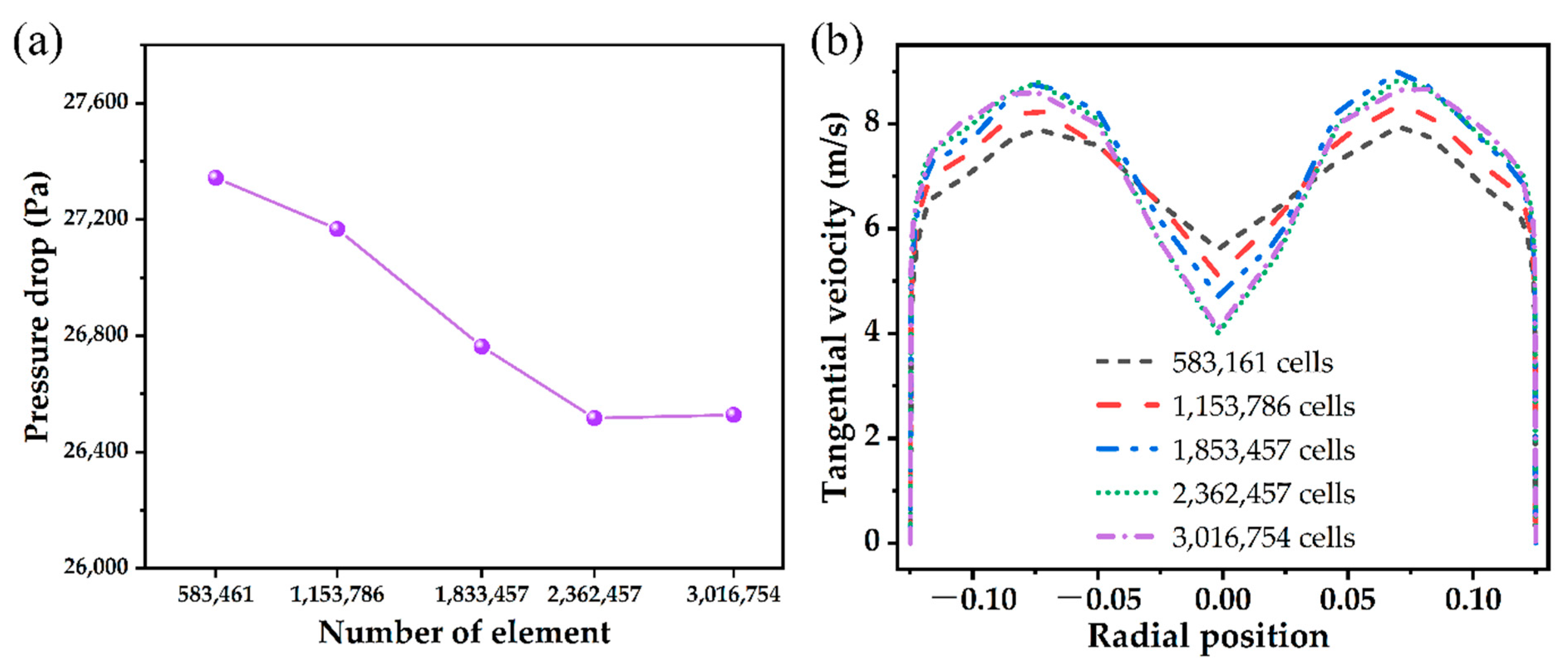
Grid independence analysis is necessary in CFD simulation, which starts with a coarse grid and gradually refines the grid until the variation observed in the results is less than a predefined acceptable error. The cyclone separator results were calculated five times using the Fluent meshing method with different mesh sizes. In order to ensure that the continuously smaller grid size was used to enhance the results in the calculation, the grid independence analysis was carried out. Each calculation was analyzed with different grid sizes under the same boundary and operating conditions. The grid sizes ranged from 583,461 (i.e., coarse grid) to 3,016,754 (i.e., fine grid). The total pressure drop and tangential velocity distributions calculated at different grid sizes are shown in Figure 4. It should be noted that the tangential velocity profiles given here were evaluated on the plane y = 950 mm from the bottom of the cyclone separator. It can be seen from the figure that the difference in pressure drop between the finest grids and the coarsest grids was less than 3.1%. The 2,362,457 and 3,016,754 grids have a pressure drop difference of 0.2% and the gas tangential velocity curves almost overlap, indicating that the simulation results within the grid range are less affected by the grid. In summary, 2,362,457 polyhedral meshes were chosen to reduce the computational effort in the simulation, as shown in Figure 5. For the other cyclonic separators discussed using different structures, the same CFD mesh generation method was also used to ensure acceptable computational time and grid independence.
2.4. Verification of Simulation
In order to verify the accuracy of the simulation calculation model, data were collected from the production site and the oligomers collected by B/C and D1~4 were quantified in the discharge tank. The quantitative data from the two production lines shown in Figure 1 were compared with the simulation data to verify the accuracy of the simulation calculations.
When the discharge tank was filled, the on-site workers removed the oligomers, and the mass of the oligomers was 200 L each time. The number of times the oligomers were extracted from the two production lines in a particular year and quarter were recorded. In that year, the two production lines needed to have the oligomers extracted 38 times and 35 times, respectively, so the total volumes of oligomers separated by the cyclone separators throughout the year at each production line were 7600 L and 7000 L; similarly, the volumes of oligomers for a quarter were 2000 L and 1800 L. The six cyclone separators were simulated using the calculated boundary conditions shown in Table 2.
The separation efficiency was defined as the ratio of the mass flow rate of the droplets captured at the bottom flow port to the inlet mass flow rate from the Fluent post-processing results.
where nk is the number of k-sized particles captured per unit of time, mk is the mass flow rate of k-sized oligomers in the feed, dk is the particle diameter, and ρo is the oligomer density.
Six cyclone separators in series with a mixed media flow rate of 7.5 kg/s and an oligomer mass concentration of 0.0033% were calculated to obtain an oligomer mass flow rate (Qm) of 2.48 × 10⁻⁴ kg/s for cyclone separator B, which was substituted into Fluent for simulation. The oligomer mass flow rate not separated out by each cyclone separator went to the next cyclone separator for separation. For cyclone separator B, according to the particle size distribution in Figure 3a and using Equation (6), the exhaust port is directly connected to the inlet of cyclone separator C through a short pipeline, so the mass flow rate of the liquid phase at the inlet of cyclone separator C is the mass flow rate that was not separated in cyclone separator B. The particle size distribution obtained using Fluent post-processing can be used as the inlet boundary condition for cyclone separator C. The exhaust port of cyclone separator C is connected to cyclone separator D after the pipeline and cooler, and the calculation for cyclone separator D used the particle size distribution shown in Figure 3b. The cooler between cyclone separators D1~4 has a long pipeline, so it was difficult to judge the actual droplet size and distribution after collision and aggregation in the pipeline. Therefore, it was necessary to assume that the droplet size distribution between the cyclone separator and the next cyclone separator in this process returned to the particle size distribution in this state. After processing by the six cyclone separators, the mass flow rate of the remaining unseparated oligomers was 0.56 × 10⁻⁴ kg/s.
From the oligomer density (ρo), the oligomer volume flow rate was calculated using the following equation:
The simulated separation efficiency and the calculated oligomer content throughput of the six separators are shown in Table 3. According to the actual operation of the cyclone separator, it operated for an average of 2000 h in a quarter and 8000 h in a year. The oligomer content generated in one quarter of operation of separator B is 2408 L. The calculated oligomer content and separation volume of the other separators are shown in Table 3.
The volume of oligomers that can be separated by all six separators in one quarter is 1864.97 L, as calculated from Table 3, which is equivalent to 7459.88 L in one year. In comparison, the volumes of oligomers separated in one quarter in the field were 1800 L and 2000 L with a maximum relative error of 7.24%, and the volumes of oligomers separated in one year in the field were 7000 L and 7600 L with a maximum relative error of 6.57%. Due to the uncertainty of the simulated results and the differences in the values of physical parameters such as density, viscosity, particle size distribution, etc., the relative error between the simulated results and the actual field results is generally acceptable, as it falls within 10%. Therefore, the simulation results are considered verified by the field data and can be considered for use in engineering applications. The numerical model established herein can thus well predict the gas–liquid separation behavior within and the hydrodynamic characteristics of the cyclone separator.
3. Experimental Design
The experimental design for the function of the D1 separator in the high-pressure polyethylene process was carried out using the boundary conditions of D1 as stated in Table 2 and Figure 3b. Due to the interactions between the various structural factors of the cyclone separator, its performance cannot be analyzed based on a single structure. The size matching and restriction relationship between the various structures should be considered comprehensively in order to design a better cyclone separator. The fastest and most effective method for establishing the restriction and matching relationship is through the experimental method, but for multiple factors, wherein each factor has a number of levels, it is necessary to consider multiple test factors at the same time. If this full test design was adopted, the workload would be unmanageable, so the experiment utilized the Taguchi design method [54], which is often used to improve the quality of products in manufacturing. This method is mainly used in the field of engineering design and industrial engineering to achieve improvements in the performance of an existing system by optimizing the design parameters [55]. The purpose of this experimental design is to reduce and control the changes in process or design parameters to improve the system’s performance characteristics. Through analysis of the experimental results, the significance of the factors and the analysis of variance can be obtained. The influence of each parameter on performance can be determined, the optimal combination can be calculated, and the linear regression equation can be optimized.
In the high-pressure production environment, the size and shape of the structure will be subject to many restrictions. The diameters of the inlet and outlet are affected by the treatment capacity and are not considered to be design variables. Preliminary analysis shows that the diameter of the umbrella structure has a small effect on the separation effect and is also not used as a design variable. The variables selected for the design of experiments (DOE) were cylinder diameter (D), cylinder height (Hcy), cone diameter (Dc), cone height (Hc), guide vane height (hv), guide vane angle (αv), exhaust pipe extension length (he), and umbrella structure height (hum). The above eight factors were studied at three levels and an experimental design was carried out using a three-level orthogonal table with eight structural parameters of L27(133). The three levels of the above factors are listed in Table 4.
An orthogonal table is a fractional factorial design used to form a design matrix for multiple combinations of design factors, and the response values were predicted experimentally or theoretically based on the different combinations of design factors. The orthogonal table gave 27 combinations of design parameters, and based on these combinations, the separation efficiency and pressure drop responses were calculated using Fluent. The separation efficiency is the ratio of the mass flow rate between the bottom flow port and the inlet of the cyclone separator, as shown in Equation (6), and the pressure drop is the static pressure difference between the inlet and exhaust ports. In this Taguchi design, the signal-to-noise ratios (SNRs) of separation efficiency and pressure drop were calculated. The separation efficiency was optimized for both reactions by using the maxims of “larger is better” and “smaller is better”, respectively. The SNRs for pressure drop and separation efficiency were calculated according to these equations [55]:
Larger is better:
Smaller is better:
where Y is the response variable. Table 5 lists the pressure drop, separation efficiency, and their respective SNRs for each simulated operation.
4. Results and Discussion
4.1. Analysis of the Control Factors
Based on the results in Table 5, further analysis was performed to analyze the effect of each factor on the separation efficiency and pressure drop using Taguchi’s SNR response table and to analyze the optimal combination of structural parameters. The results of the simulations with different combinations of structural parameters at different levels were calculated and analyzed, and the average SNR responses of separation efficiency and pressure drop are shown in Table 6. The table shows the SNR ratio at each factor level and the trend of each factor as it changes from level 1 to level 3. The greater the change, the greater the influence of the factors. The degree of influence was different for the eight structural parameters. For the evaluation index of separation efficiency, the influencing factors are, in order of priority: guide vane angle (αv) > guide vane height (hv) > cone diameter (Dc) > cylinder diameter (D) > exhaust pipe extension length (he) > cylinder length (Hcy) > umbrella structure height (hum) > cone height (hc). For the evaluation index of pressure drop, the degree of influence of structural parameters was: guide vane angle (αv) > guide vane height (hv) > cone diameter (Dc) > cylinder length (Hcy) > exhaust pipe extension length (he) > cone height (hc) > cylinder diameter (D) > umbrella structure height (hum). The optimal experimental parameters for the eight factors corresponding to the two responses and the trend of the effect of each factor on the response values can be determined from the SNR main effects plot in Figure 6. The horizontal axis of the plot shows the values of each parameter at three different levels, and the vertical axis shows the response values (average SNR). The optimal parameter levels for separation efficiency were taken as 220 mm, 641 mm, 200 mm, 282 mm, 75 mm, 15°, 131 mm, and 78 mm. The optimal parameter levels for pressure drop were taken as 280 mm, 841 mm, 200 mm, 202 mm, 75 mm, 45°, 91 mm, and 58 mm.
4.2. Analysis of Variance
The significance of the developed response linear mathematical equations was verified using analysis of variance (ANOVA). P-tests were performed based on the response results and geometric factors. The sources of variation, degrees of freedom (DF), sum of squares (SS), mean square (MS), F-value (F), and p-value (p) of the response results for different size parameters are shown in Table 7.
For ANOVA, if the p-value of any term is less than the confidence level, the term is said to have a significant effect on the response, and the p-value was calculated at a 99% confidence interval (significance level α = 0.01). The ANOVA results show that the eight factors, cylinder diameter (D), cylinder length (Hcy), cone diameter (Dc), cone height (Hc), guide vane height (hv), guide vane angle (αv), exhaust pipe extension length (he), and umbrella structure height (hum), all had significant effects on separation efficiency (p < 0.01), and all eight factors also had significant effects on pressure drop (p < 0.01), indicating that the stability of the established model was at 95% of the confidence limit.
4.3. Regression Analysis
Regression analysis was performed using SPSS statistical tools. An important goal of regression analysis is to create regression equations for optimization. In addition, the quality of the established regression equation can be verified via regression analysis [55]. The regression analysis considered a total of eight independent variables, D, Hcy, Dc, Hc, hv, αv, he, and hum, and two dependent variables, η and ΔP. In order to determine the regression coefficients, the mean of each variable must be calculated. Then, the sum of squares of each variable was predicted; the sum of squares is the square of the difference between each variable and its overall mean. After, the multiplication cross of each independent variable and the dependent variable was determined. Based on the secondary data resources obtained from these calculations, the regression coefficients were predicted using the least squares method. The regression equation for each dependent variable was derived from this regression coefficient. Subsequently, the standard error (SE) was predicted from the ratio of the standard deviation to the square root of the total sample. The T-value of each variable was predicted from the ratio of the regression coefficient to the SE. The F-value was calculated from the ratio of the mean squared deviation to the residuals of the ANOVA. A p-value of less than 0.01 indicated a significant effect on the response value. Similarly, for p-values greater than 0.01, the results for the response values were insignificant. The regression analysis is reported in Table 8, where all eight factors were found to have a significant effect on the separation efficiency and pressure drop.
Another important factor in regression analysis is R2 (coefficient of determination), which is defined as the ratio of the variance of the independent variables that have been accounted for by all the independent variables in the model to the total variance of the independent variables. When R2 converges to the unit value of 1, it indicates a good fit between this parameter and the response. The R2 values of the response parameters (η and ΔP) were 0.998 and 0.999, respectively, indicating that the established linear equation had a high optimization effect. Regression analysis was performed using SPSS software to obtain a mathematical model based on eight parameters, D, Hcy, Dc, Hc, hv, αv, he, and hum, and to predict the separation efficiency and pressure drop. The regression equations are shown in Equation (10) and Equation (11), respectively. To further verify the accuracy of the regression equation, the predicted values of the regression equation were compared with the simulated values shown in Figure 7. The comparison results showed that the predicted values were in good agreement with the experimental values, and in the correspondence between the residual values and the predicted values of the regression equation, the residual values showed an irregular distribution, which indicated that the calculation results were good. As shown in Table 9, the calculated separation efficiency and pressure drop of the optimal separation efficiency and optimal pressure drop combination with the original structure were compared with the predicted values of the regression equation. The results show that the separation efficiency of the optimal separation efficiency combination was improved by 98.7% compared with the original structure, and the maximum prediction error of the regression equation was 3.1%. The optimal pressure drop combination reduced the pressure drop by 42.8% compared to the original structure, and the maximum prediction error of the regression equation was 3.6%.
The parameters of the guide vane and the diameters of the cylinder section and the cone section, which have a greater influence on the separation performance and pressure drop, were selected for analysis. The performance parameters and the variable surfaces are shown in Figure 8. As the guide vane angle increases, the separation efficiency of the cyclone separator becomes smaller and the pressure drop decreases; as the guide vane height increases, the separation efficiency increases and the pressure drop decreases; as the cylinder diameter increases, the separation efficiency decreases and the pressure drop also decreases; as the cone diameter increases, the separation efficiency increases and the pressure drop decreases.
4.4. Multi-Objective Optimization
The previous paper is based on statistical principles, using the trend and variance analysis of the influence of factors on a single inspection target to obtain a preliminary optimization scheme. This analysis method is more systematic and scientific. However, in the actual multi-objective optimization problem, it is often necessary to account for changes in the objectives and conduct a systematic analysis to obtain the highest possible benefits with the lowest possible comprehensive consumption, and then determine a more relevant optimization scheme. The larger the ratio between the efficiency class objective and the energy consumption class objective, the better the optimization scheme. The concept of relative separation efficiency was introduced, which was expressed by η’, as shown in the following equation:
where η is the separation efficiency obtained from the test and η0 is the separation efficiency of the original structure.
The concept of relative pressure drop was also introduced and expressed by ΔP′, as shown in the following equation:
where ΔP is the pressure drop obtained from the simulation and ΔP0 is the pressure drop of the original structure.
Among the two objectives to be investigated in the comprehensive analysis, the relative separation efficiency η′ compared to the original structure belongs to the benefit target and the relative pressure drop ΔP′ belongs to the energy consumption target. This was expressed in terms of the energy-efficiency factor, σ, as shown in the following equation:
The σ values were calculated separately for each test group, and the SNRs are shown in Table 5. From Table 10, it can be seen that the three factors that have the greatest influence on the σ value are the guide vane height (hv), the cone diameter (Dc) and the cylinder diameter (D). The surface plot of the performance parameters and variables analyzing the influence of the three factors on the σ value is shown in Figure 9. As the height of the guide vanes (hv) and the cone diameter (Dc) increase, the σ value increases accordingly; as the cylinder diameter (D) decreases, the σ value also decreases accordingly.
The regression analysis was performed using SPSS software, and a mathematical model based on the parameters D, Hcy, Dc, Hc, hv, αv, he and hum was obtained with an R2 of 0.974. The regression analysis is reported in Table 11. D, Dc, hv, αv, he, and hum had a significant effect on the response values, and Hcy and Hc did not have a significant effect on the response values. The established regression equation is shown in Equation (15). As shown in Figure 10, the predicted values agree well with the experimental values, and the residual values are scattered and show irregular distribution. The established linear equation has a high optimization effect and can thus be used to predict the separation efficiency and pressure drop.
The optimal value of the regression equation was solved using the linprog function in MATLAB R2018a software. The larger the value of σ, the better. The lower and upper limits were set to 220, 641, 100, 202, 45, 15, 91, 58 and 280, 841, 200, 282, 75, 45, 131, 78, respectively. The optimal solution was calculated to be σ = 1.7595, at which time the values of the independent variables were 220, 641, 200, 282, 75, 15, 131, 78. The comprehensive optimal combination was the same as the optimal separation efficiency combination.
4.5. Improved and Original Structure Comparison
The comprehensive optimal combination parameters were applied to the cyclone separator, and the optimized model is shown in Figure 11, where the cyclone separator is narrower and smaller, the cylinder and cone joints are smoother, and the guide vane angle is inclined and the height is taller. The simulated value of the cyclone separator was in good agreement with the predicted value of the equation, with an error of 5.5%. Under the optimal structural parameters, the improved structure increases the separation efficiency by 98.7% compared to the original structure, while the pressure drop only increases by 8.2%. The calculation results for substituting this comprehensive optimal combination into the high-pressure polyethylene process are shown in Table 12. Separators D1~4 were all improved, resulting in a separation efficiency which indicated that 2194 L of oligomers could be separated in one quarter and 8775 L could be separated in one year. The total separation efficiency of the six cyclone separators could thus reach 91.1%, which is 17.7% higher than the separation efficiency achieved by the original structure, which was 77.4%. Additionally, the improved structure could effectively reduce the required frequency of filter cleaning.
Figure 12 shows the pressure contour of the original structure and that of the improved structure. The results show that the pressure was distributed in a V-shape along the radial direction, and the cyclone separator showed good symmetry in terms of overall pressure distribution, with a low-pressure zone at the center. This is due to the presence of a highly intensified forced vortex due to the high vortex velocity. The maximum pressure of the original structure of the cyclone separator was located in the cylinder wall area, and the pressure decreased gradually from the cylinder wall to the exhaust pipe. The maximum pressure of the improved cyclone separator structure was located in the channel in front of the guide vane, followed by the wall area, and the pressure decreased gradually from the cylinder wall to the exhaust pipe. This is because when the mixed medium enters the cyclone tangentially, it is subject to the reaction force of the circular wall of the cyclone separator and generates vortex. As the angle of the guide vanes of the improved structure becomes smaller, the axial force generated when its feed fluid hits the wall of the guide vanes also becomes smaller, resulting in the highest pressure in the channel, which was also the main reason for the high pressure drop of the improved structure compared with that of the original structure. After the feed fluid passes through the guide vane, the pressure distribution in the cyclone separator was similar to that of the original structure, and the pressure decreased from the cylinder wall to the center of the cyclone separator. The decrease of the cylinder diameter and the increase of the cone diameter smoothed out the area where the cylinder and cone made contact, which helped to reduce the pressure drop.
Figure 12 shows the tangential and axial velocity distribution contours for the two cyclone separators. The radial distribution of tangential velocity and axial velocity is shown in Figure 13, where R is the radius of the cylinder of the corresponding structure and r is the radial position. The positions of the three lines selected in the radial direction are shown in Figure 11, where the positions P0 (P0′) and P1 (P1′) trisect the height of the cylinder, the position P2 is the contact area of the cylinder and cone, and the lengths of all three lines are the diameters of the cylinders. Since the wall was set as a no-slip wall boundary condition (the fluid has zero relative velocity at the wall), and the original structure and the improved structure were different here, the velocity is zero in some areas on Figure 13c,f. In a centrifugal separator, the separation efficiency is mainly affected by the centrifugal force, which is mainly related to the tangential velocity, and the centrifugal force generated in the cyclone separator is greater when there is a larger tangential velocity. The larger centrifugal force allows more droplets to hit against the wall, thus increasing the collection of the liquid phase. Therefore, the tangential velocity magnitude in the cyclone separator is very important for separation efficiency. The maximum tangential velocity of the original structure occurs in the bottom area of the exhaust pipe of the cyclone separator, and the maximum tangential velocity of the improved structure occurs in the flow channel of the guide vanes. This is because the guide vane angle and guide vane height are optimized so that the mixed media has a higher tangential velocity after flowing through the flow channel, and thus the mixed media has a higher tangential velocity for separation in the cylinder. The tangential velocities of the two forms were in good symmetry. From the tangential velocity distribution of the two cyclone separators in Figure 13, both tangential velocities have an M-shaped distribution, with lower tangential velocity at the center, gradually increasing tangential velocity in the region of 0 ≤ |R′| < 2/3R, and decreasing tangential velocity in the region of 2/3R ≤ |R′| < R for both.
In order to compare the axial velocity of the different structure forms, it was specified that the axial velocity values are positive along the axis downward with the positive direction and negative along the axis upward with the negative direction. From the axial velocity contour in Figure 12, it can be seen that both cyclone structures show relatively good symmetry, and the maximum axial velocity of both structures is in a small area near the outer wall of the exhaust pipe, which is because a small amount of mixed medium will escape directly from here along the exhaust pipe. From Figure 13, the axial velocity is smaller from the wall of the cylinder to the position near the central axis, and it has an M-shaped distribution. At the same cross-sectional position, the axial velocity increased and then decreased along the radial direction from the center to the wall. This is due to the existence of upstream flow and downstream flow in the separator. Numerically, the velocity of the upstream flow was greater than that of the downstream flow, which is due to the upstream flow flowing to the exhaust pipe. When the fluid flows through the exhaust pipe, the flow area decreases, resulting in an increase in its velocity. In the downflow region, the maximum axial velocity was close to the side wall, and its size gradually decreased as the axial position decreased. In the original structure, the phenomenon of large axial velocity and asymmetric distribution of axial velocity in the cone section was also observed in some areas of the cone wall, as evidenced in Figure 13f, indicating that the structural ratio of the cylinder section to the cone section affected the stability of the axial velocity in this area. The improved structure did not have this phenomenon, which indicates that the structural ratio of the cylinder and cone sections of the improved structure was more conducive to the smooth flow of fluid in this area.
5. Conclusions
The Taguchi design method was used to optimize the structural design of the cyclone separator, and the best mathematical equations for the two response parameters (η and ΔP) and the equation for the energy-efficiency factor, σ, were fitted. The numerical simulation method, Taguchi method, and multi-objective optimization method were applied to investigate the effects of eight structural parameters on the separation performance of the high-pressure polyethylene cyclone separator. The conclusions are as follows:
- (1)
- For the separation efficiency, the influencing factors were, in order of priority: guide vane angle > guide vane height > cone diameter > cylinder diameter > exhaust pipe extension length > cylinder height > umbrella structure height > cone height. The optimal parameter levels for separation efficiency were taken as: cylinder diameter at 220 mm, cylinder height at 641 mm, cone diameter at 200 mm, cone height at 282 mm, guide vane height at 75 mm, guide vane angle at 15°, exhaust pipe extension length at 131 mm, and umbrella structure height at 78 mm. The optimal combination for separation efficiency improved the separation efficiency by 98.7% compared with that of the original structure. The mathematical equations for separation efficiency and the eight parameters were also obtained and predicted with a maximum error of 3.1%.
- (2)
- For the pressure drop, the influencing factors were, in order of priority: guide vane angle > guide vane height > cone diameter > cylinder length > exhaust pipe extension length > cone height > cylinder diameter > umbrella structure height. The optimal parameter levels for pressure drop were taken as: cylinder diameter at 280 mm, cylinder height at 841 mm, cone diameter at 200 mm, cone height at 202 mm, guide vane height at 75 mm, guide vane angle at 45°, exhaust pipe extension length at 91 mm, and umbrella structure height at 58 mm. The optimal pressure drop combination reduced the pressure drop by 42.8% compared with that of the original structure. The mathematical equations for pressure drop and the eight parameters were also obtained and predicted, and the maximum error of the predicted value was 3.6%.
- (3)
- An energy-efficiency factor was defined and used to reduce the multi-objective optimization problem and achieve a higher separation efficiency and lower pressure drop. The guide vane height, cone diameter, and cylinder diameter had the greatest influence on the comprehensive performance of the cyclone separator and the comprehensive optimal combination was the same as the optimal separation efficiency combination. The improved structure increased the separation efficiency by 98.7% compared to the original structure, while the pressure drop increased by only 8.2%. When the improved structure was applied in the high-pressure polyethylene process, the separation efficiency reached 91.1%, which was 17.7% higher than that of the original structure, which could thus effectively reduce the frequency of filter cleaning and greatly improve the production efficiency. The mathematical equations of the energy-efficiency factor and the eight parameters were also obtained and predicted, and the simulated values of the improved structure were in good agreement with the predicted values, with a relative error within 5.5%.
Although the proposed improved structure is effective in the relevant operating and physical parameters of the cyclone separator in the high-pressure polyethylene process, it may not be capable of achieving this effect under other process conditions. The cyclone separator behaves differently under different physical and operating conditions. Therefore, more work can be done on the applicability of the cyclone separator equipment to study the range of process parameters to which the cyclone separator can be adapted.
Author Contributions
Conceptualization, B.H. and B.G.; Methodology, B.H.; Software, S.L.; Validation, C.W. and B.G.; Formal Analysis, B.H.; Investigation, S.L.; Resources, C.W.; Data Curation, S.L.; Writing—Original Draft Preparation, S.L.; Writing—Review & Editing, B.H. and B.G.; Visualization, S.L.; Supervision, B.G.; Project Administration, B.G.; Funding Acquisition, B.G. All authors have read and agreed to the published version of the manuscript.
Funding
This research received no external funding.
Data Availability Statement
Data sharing not applicable.
Acknowledgments
The authors acknowledge constructive comments of Baoling Han from Beijing Yanhua Engineering Construction Company and the partial calculation work done by Suli Yang from Hebei University of Technology.
Conflicts of Interest
The authors declare no conflict of interest.
Nomenclature
| General symbols | |
| d | Inlet diameter (mm) |
| D | Cylinder diameter (mm) |
| Db | Bottom flow pipe diameter (mm) |
| Dc | Cone diameter (mm) |
| De | Exhaust pipe diameter (mm) |
| Dij | Stress diffusion |
| dk | Particle diameter (μm) |
| H | Total height of the cyclone separator (mm) |
| Hb | Bottom flow pipe height (mm) |
| Hc | Cone height (mm) |
| Hcy | Cylinder height (mm) |
| he | Exhaust pipe extension length (mm) |
| hum | Umbrella structure height (mm) |
| hv | Guide vane height (mm) |
| mk | Mass flow rate of k-sized oligomers in the feed |
| nk | Number of k-sized particles captured per unit of time |
| Pij | Shear production |
| Qm | Mass flow rate of oligomers |
| Qv | Volume flow rate of oligomers |
| R | Cylinder radius of the corresponding structure |
| r | Radial position |
| ui | Time-averaged fluid velocity i (m/s) |
| u′i | Fluctuating velocity to direction i (m/s) |
| Sub-grid scale velocity (m/s) | |
| Y | Response variable |
| Greek symbols | |
| αv | Guide vane angle (°) |
| βum | Umbrella structure angle (mm) |
| δij | Kronecker delta |
| ΔP | Pressure drop (Pa) |
| ΔP′ | Relative pressure drop (Pa) |
| εij | Source term |
| η | Separation efficiency |
| η′ | Relative separation efficiency |
| μ | Viscosity (kg/m.s) |
| ρ | Gas density (kg/m3) |
| ρo | Oligomer density (kg/m3) |
| σ | Energy-efficiency factor |
| μt | Eddy viscosity (kg/m.s) |
| Φij | Pressure-strain |
References
- Mazyan, W.I.; Ahmadi, A.; Brinkerhoff, J.; Ahmed, H.; Hoorfar, M. Enhancement of Cyclone Solid Particle Separation Performance Based on Geometrical Modification: Numerical Analysis. Sep. Purif. Technol. 2018, 191, 276–285. [Google Scholar] [CrossRef]
- Vieira, L.G.M.; Silva, D.O.; Barrozo, M.A.S. Effect of Inlet Diameter on the Performance of a Filtering Hydrocyclone Separator. Chem. Eng. Technol. 2016, 39, 1406–1412. [Google Scholar] [CrossRef]
- Chi, Y.; Meng, X.; Zhang, R.; Liu, H.; Liu, Z. Progress in numerical simulation of liquid-liquid cyclone separator. Chin. J. Process Eng. 2021, 21, 1132–1141. [Google Scholar]
- El-Emam, M.A.; Shi, W.; Zhou, L. CFD-DEM Simulation and Optimization of Gas-Cyclone Performance with Realistic Macroscopic Particulate Matter. Adv. Powder Technol. 2019, 30, 2686–2702. [Google Scholar] [CrossRef]
- Yang, L.; Zhang, J.; Ma, Y.; Xu, J.; Wang, J. Experimental and Numerical Study of Separation Characteristics in Gas-Liquid Cylindrical Cyclone. Chem. Eng. Sci. 2020, 214, 115362. [Google Scholar] [CrossRef]
- Katare, P.; Krupan, A.; Dewasthale, A.; Datar, A.; Dalkilic, A.S. CFD Analysis of Cyclone Separator Used for Fine Filtration in Separation Industry. Case Stud. Therm. Eng. 2021, 28, 101384. [Google Scholar] [CrossRef]
- Bymaster, A.; Olson, M.; Grave, E.; Svedeman, S.J.; Viana, F.; Akdim, M.R.; Mikkelsen, R. High Pressure Gas-Liquid Separation: An Experimental Study on Separator Performance of Natural Gas Streams at Elevated Pressures. In Proceedings of the Offshore Technology Conference, Houston, TX, USA, 2–5 May 2011. [Google Scholar]
- Dueck, J.; Farghaly, M.; Neesse, T. The Theoretical Partition Curve of the Hydrocyclone. Miner. Eng. 2014, 62, 25–30. [Google Scholar] [CrossRef]
- He, F.; Wang, H.; Wang, J.; Li, S.; Fan, Y.; Xu, X. Experimental Study of Mini-Hydrocyclones with Different Vortex Finder Depths Using Particle Imaging Velocimetry. Sep. Purif. Technol. 2020, 236, 116296. [Google Scholar] [CrossRef]
- Jiang, L.; Liu, P.; Yang, X.; Zhang, Y.; Li, X.; Zhang, Y.; Wang, H. Experimental Research on the Separation Performance of W-Shaped Hydrocyclone. Powder Technol. 2020, 372, 532–541. [Google Scholar] [CrossRef]
- Kozić, M.; Ristic, S.; Puharic, M.; Linic, S. CFD Analysis of the Influence of Centrifugal Separator Geometry Modification on the Pulverized Coal Distribution at the Burners. Trans. FAMENA 2014, 38, 25–36. [Google Scholar]
- Ye, J.; Xu, Y.; Song, X.; Yu, J. Novel Conical Section Design for Ultra-Fine Particles Classification by a Hydrocyclone. Chem. Eng. Res. Des. 2019, 144, 135–149. [Google Scholar] [CrossRef]
- Fadaei, M.; Ameri, M.J.; Rafiei, Y.; Ghorbanpour, K. A Modified Semi-Empirical Correlation for Designing Two-Phase Separators. J. Pet. Sci. Eng. 2021, 205, 108782. [Google Scholar] [CrossRef]
- Hwang, K.-J.; Hwang, Y.-W.; Yoshida, H. Design of Novel Hydrocyclone for Improving Fine Particle Separation Using Computational Fluid Dynamics. Chem. Eng. Sci. 2013, 85, 62–68. [Google Scholar] [CrossRef]
- Tian, J.; Ni, L.; Song, T.; Shen, C.; Yao, Y.; Zhao, J. Numerical Study of Foulant-Water Separation Using Hydrocyclones Enhanced by Reflux Device: Effect of Underflow Pipe Diameter. Sep. Purif. Technol. 2019, 215, 10–24. [Google Scholar] [CrossRef]
- Yohana, E.; Tauviqirrahman, M.; Yusuf, B.; Choi, K.-H.; Paramita, V. Effect of Vortex Limiter Position and Metal Rod Insertion on the Flow Field, Heat Rate, and Performance of Cyclone Separator. Powder Technol. 2021, 377, 464–475. [Google Scholar] [CrossRef]
- Chu, K.; Chen, J.; Yu, A.B.; Williams, R.A. Numerical Studies of Multiphase Flow and Separation Performance of Natural Medium Cyclones for Recovering Waste Coal. Powder Technol. 2017, 314, 532–541. [Google Scholar] [CrossRef]
- Pei, B.; Yang, L.; Dong, K.; Jiang, Y.; Du, X.; Wang, B. The Effect of Cross-Shaped Vortex Finder on the Performance of Cyclone Separator. Powder Technol. 2017, 313, 135–144. [Google Scholar] [CrossRef]
- Shukla, S.K.; Shukla, P.; Ghosh, P. The Effect of Modeling of Velocity Fluctuations on Prediction of Collection Efficiency of Cyclone Separators. Appl. Math. Model. 2013, 37, 5774–5789. [Google Scholar] [CrossRef]
- Qiu, S.; Wang, G. Effects of Reservoir Parameters on Separation Behaviors of the Spiral Separator for Purifying Natural Gas Hydrate. Energies 2020, 13, 5346. [Google Scholar] [CrossRef]
- Gao, X.; Chen, J.; Feng, J.; Peng, X. Numerical Investigation of the Effects of the Central Channel on the Flow Field in an Oil–Gas Cyclone Separator. Comput. Fluids 2014, 92, 45–55. [Google Scholar] [CrossRef]
- Kępa, A. The Efficiency Improvement of a Large-Diameter Cyclone—The CFD Calculations. Sep. Purif. Technol. 2013, 118, 105–111. [Google Scholar] [CrossRef]
- Chuah, T.G.; Gimbun, J.; Choong, T.S.Y. A CFD Study of the Effect of Cone Dimensions on Sampling Aerocyclones Performance and Hydrodynamics. Powder Technol. 2006, 162, 126–132. [Google Scholar] [CrossRef]
- Zhang, H.; Dewil, R.; Degrève, J.; Baeyens, J. The Design of Cyclonic Pre-Heaters in Suspension Cement Kilns. Int. J. Sustain. Eng. 2014, 7, 307–312. [Google Scholar] [CrossRef] [Green Version]
- Wang, Y.; Chen, J.; Yang, Y.; Han, M.; Zhou, Y.; Ye, S.; Yan, C.; Yue, T. Experimental and Numerical Performance Study of a Downward Dual-Inlet Gas-Liquid Cylindrical Cyclone (GLCC). Chem. Eng. Sci. 2021, 238, 116595. [Google Scholar] [CrossRef]
- Lim, J.-H.; Oh, S.-H.; Kang, S.; Lee, K.-J.; Yook, S.-J. Development of Cutoff Size Adjustable Omnidirectional Inlet Cyclone Separator. Sep. Purif. Technol. 2021, 276, 119397. [Google Scholar] [CrossRef]
- Safikhani, H.; Mehrabian, P. Numerical Study of Flow Field in New Cyclone Separators. Adv. Powder Technol. 2016, 27, 379–387. [Google Scholar] [CrossRef]
- Liu, L.; Bai, B. Numerical Study on Swirling Flow and Separation Performance of Swirl Vane Separator. Interfacial Phenom. Heat Transf. 2017, 5, 9–21. [Google Scholar] [CrossRef] [Green Version]
- Elsayed, K.; Lacor, C. The Effect of Cyclone Vortex Finder Dimensions on the Flow Pattern and Performance Using LES. Comput. Fluids 2013, 71, 224–239. [Google Scholar] [CrossRef]
- Hamdy, O.; Bassily, M.A.; El-Batsh, H.M.; Mekhail, T.A. Numerical Study of the Effect of Changing the Cyclone Cone Length on the Gas Flow Field. Appl. Math. Model. 2017, 46, 81–97. [Google Scholar] [CrossRef]
- Shastri, R.; Brar, L.S. Numerical Investigations of the Flow-Field inside Cyclone Separators with Different Cylinder-to-Cone Ratios Using Large-Eddy Simulation. Sep. Purif. Technol. 2020, 249, 117149. [Google Scholar] [CrossRef]
- Misiulia, D.; Elsayed, K.; Andersson, A.G. Geometry Optimization of a Deswirler for Cyclone Separator in Terms of Pressure Drop Using CFD and Artificial Neural Network. Sep. Purif. Technol. 2017, 185, 10–23. [Google Scholar] [CrossRef]
- Zhou, F.; Sun, G.; Han, X.; Zhang, Y.; Bi, W. Experimental and CFD Study on Effects of Spiral Guide Vanes on Cyclone Performance. Adv. Powder Technol. 2018, 29, 3394–3403. [Google Scholar] [CrossRef]
- Misiulia, D.I.; Kuz’min, V.V.; Markov, V.A. Developing an Untwisting Device for Cyclones and Estimating Its Parameters. Theor. Found. Chem. Eng. 2013, 47, 274–283. [Google Scholar] [CrossRef]
- Wasilewski, M.; Singh Brar, L.; Ligus, G. Effect of the Central Rod Dimensions on the Performance of Cyclone Separators—Optimization Study. Sep. Purif. Technol. 2021, 274, 119020. [Google Scholar] [CrossRef]
- Ficici, F.; Ari, V. Optimization of the Preheater Cyclone Separators Used in the Cement Industry. Int. J. Green Energy 2013, 10, 12–27. [Google Scholar] [CrossRef]
- Safikhani, H.; Hajiloo, A.; Ranjbar, M.A. Modeling and Multi-Objective Optimization of Cyclone Separators Using CFD and Genetic Algorithms. Comput. Chem. Eng. 2011, 35, 1064–1071. [Google Scholar] [CrossRef]
- Sankar, P.S.; Prasad, R.K. Process Modeling and Particle Flow Simulation of Sand Separation in Cyclone Separator. Part. Sci. Technol. 2015, 33, 385–392. [Google Scholar] [CrossRef]
- Mariani, F.; Risi, F.; Grimaldi, C.N. Separation Efficiency and Heat Exchange Optimization in a Cyclone. Sep. Purif. Technol. 2017, 179, 393–402. [Google Scholar] [CrossRef]
- Venkatesh, S.; Suresh Kumar, R.; Sivapirakasam, S.P.; Sakthivel, M.; Venkatesh, D.; Yasar Arafath, S. Multi-Objective Optimization, Experimental and CFD Approach for Performance Analysis in Square Cyclone Separator. Powder Technol. 2020, 371, 115–129. [Google Scholar] [CrossRef]
- Babaoğlu, N.U.; Hosseini, S.H.; Ahmadi, G.; Elsayed, K. The Effect of Axial Cyclone Inlet Velocity and Geometrical Dimensions on the Flow Pattern, Performance, and Acoustic Noise. Powder Technol. 2022, 407, 117692. [Google Scholar] [CrossRef]
- Shastri, R.; Singh Brar, L.; Elsayed, K. Multi-Objective Optimization of Cyclone Separators Using Mathematical Modelling and Large-Eddy Simulation for a Fixed Total Height Condition. Sep. Purif. Technol. 2022, 291, 120968. [Google Scholar] [CrossRef]
- Elsayed, K.; Parvaz, F.; Hosseini, S.H.; Ahmadi, G. Influence of the Dipleg and Dustbin Dimensions on Performance of Gas Cyclones: An Optimization Study. Sep. Purif. Technol. 2020, 239, 116553. [Google Scholar] [CrossRef]
- Brar, L.S.; Elsayed, K. Analysis and Optimization of Cyclone Separators with Eccentric Vortex Finders Using Large Eddy Simulation and Artificial Neural Network. Sep. Purif. Technol. 2018, 207, 269–283. [Google Scholar] [CrossRef]
- Yao, X.; Zuo, P.; Lu, C.; E, C.; Liu, M. Characteristics of Flow and Liquid Distribution in a Gas–Liquid Vortex Separator with Multi Spiral Arms. Particuology 2022, 68, 101–113. [Google Scholar] [CrossRef]
- Baltrėnas, P.; Chlebnikovas, A. Removal of Fine Solid Particles in Aggressive Gas Flows in a Newly Designed Multi-Channel Cyclone. Powder Technol. 2019, 356, 480–492. [Google Scholar] [CrossRef]
- Zhou, W.; E, C.; Fan, Y.; Wang, K.; Lu, C. Experimental Research on the Separation Characteristics of a Gas-Liquid Cyclone Separator in WGS. Powder Technol. 2020, 372, 438–447. [Google Scholar] [CrossRef]
- Elsayed, K. Optimization of the Cyclone Separator Geometry for Minimum Pressure Drop Using Co-Kriging. Powder Technol. 2015, 269, 409–424. [Google Scholar] [CrossRef]
- Elsayed, K. Design of a Novel Gas Cyclone Vortex Finder Using the Adjoint Method. Sep. Purif. Technol. 2015, 142, 274–286. [Google Scholar] [CrossRef]
- Singh, P.; Couckuyt, I.; Elsayed, K.; Deschrijver, D.; Dhaene, T. Shape Optimization of a Cyclone Separator Using Multi-Objective Surrogate-Based Optimization. Appl. Math. Model. 2016, 40, 4248–4259. [Google Scholar] [CrossRef]
- Cengel, Y.; Cimbala, J. Fluid Mechanics Fundamentals and Applications (Si Units); McGraw-Hill Higher Education: Boston, MA, USA, 2010. [Google Scholar]
- Fathizadeh, N.; Mohebbi, A.; Soltaninejad, S.; Iranmanesh, M. Design and Simulation of High Pressure Cyclones for a Gas City Gate Station Using Semi-Empirical Models, Genetic Algorithm and Computational Fluid Dynamics. J. Nat. Gas Sci. Eng. 2015, 26, 313–329. [Google Scholar] [CrossRef]
- Oh, J.; Choi, S.; Kim, J. Numerical Simulation of an Internal Flow Field in a Uniflow Cyclone Separator. Powder Technol. 2015, 274, 135–145. [Google Scholar] [CrossRef]
- Kui, C. Design of Experiments and Analysis; Tsinghua University Press: Beijing, China, 1996. [Google Scholar]
- Roy, R.K. Design of Experiments Using the Taguchi Approach: 16 Steps to Product and Process Improvement; John Wiley & Sons: New York, NY, USA, 2001. [Google Scholar]
Figure 1.
High-pressure polyethylene process flow and high-pressure separation system.

Figure 2.
Cyclone separator model.

Figure 3.
Rosin–Rammler droplet size distribution at the inlet of cyclone separator (a) B and (b) D1.
Figure 3.
Rosin–Rammler droplet size distribution at the inlet of cyclone separator (a) B and (b) D1.

Figure 4.
Grid independence verification for (a) pressure drop verification and (b) tangential velocity verification.
Figure 4.
Grid independence verification for (a) pressure drop verification and (b) tangential velocity verification.

Figure 5.
Grid division of the cyclone separator.

Figure 6.
The mean of SNR vs the geometrical parameters of (a) separation efficiency and (b) pressure drop.
Figure 6.
The mean of SNR vs the geometrical parameters of (a) separation efficiency and (b) pressure drop.

Figure 7.
From left to right: comparison of the simulated response values of separation efficiency and the predicted values of the regression equation and correspondence between residuals and predicted values of the regression equation for (a) separation efficiency and (b) pressure drop.
Figure 7.
From left to right: comparison of the simulated response values of separation efficiency and the predicted values of the regression equation and correspondence between residuals and predicted values of the regression equation for (a) separation efficiency and (b) pressure drop.

Figure 8.
The influence of guide vane and cone diameter on response parameters.

Figure 9.
The influence of guide vane height (hv), cone section diameter (Dc), and cylinder section diameter (D) on σ.
Figure 9.
The influence of guide vane height (hv), cone section diameter (Dc), and cylinder section diameter (D) on σ.

Figure 10.
(a) The relationship between simulated response value and predicted value and (b) the relationship between residual and predicted value.
Figure 10.
(a) The relationship between simulated response value and predicted value and (b) the relationship between residual and predicted value.

Figure 11.
Structure comparison: (a) original structure and (b) improved structure.

Figure 12.
The contour of the original structure and the improved structure. From top to bottom: original structure and improved structure. From left to right: pressure contour, tangential velocity contour, and axial velocity contour.
Figure 12.
The contour of the original structure and the improved structure. From top to bottom: original structure and improved structure. From left to right: pressure contour, tangential velocity contour, and axial velocity contour.

Figure 13.
The tangential velocity and axial velocity distribution of the original structure and the improved structure. From top to bottom: tangential velocity and axial velocity. From left to right: P0, P1, and P2.
Figure 13.
The tangential velocity and axial velocity distribution of the original structure and the improved structure. From top to bottom: tangential velocity and axial velocity. From left to right: P0, P1, and P2.


Table 1.
Main structural parameters of cyclone separators.
| H (mm) | Hcy (mm) | Hc (mm) | Hb (mm) | D (mm) | Dc (mm) | d (mm) | De (mm) | Db (mm) | hv (mm) | he (mm) | hum (mm) | αv (°) | βum (°) |
|---|---|---|---|---|---|---|---|---|---|---|---|---|---|
| 1750 | 741 | 242 | 169 | 250 | 150 | 77 | 77 | 20 | 45 | 91 | 68 | 30 | 30 |
Table 2.
Boundary conditions of the cyclone separator.
| Models | B | C | D1 | D2 | D3 | D4 |
|---|---|---|---|---|---|---|
| Inlet velocity (m/s) | 9.05 | 9.05 | 7.32 | 6.86 | 6.52 | 6.37 |
| Working temperature (℃) | 200 | 200 | 110 | 80.0 | 55.0 | 45.0 |
| Gaseous density (g/cm3) | 0.178 | 0.178 | 0.220 | 0.235 | 0.247 | 0.253 |
| Gaseous viscosity (cP) | 0.0150 | 0.0150 | 0.0130 | 0.0130 | 0.0110 | 0.0110 |
| Liquid density (g/cm3) | 0.740 | 0.740 | 0.740 | 0.740 | 0.740 | 0.740 |
| Liquid viscosity (cP) | 290 | 290 | 290 | 290 | 290 | 290 |
Table 3.
Separation conditions of the cyclone separator.
| Device Number | B | C | D1 | D2 | D3 | D4 |
|---|---|---|---|---|---|---|
| Separation efficiency (%) | 36.73 | 28.24 | 23.28 | 14.11 | 13.49 | 12.87 |
| Import mass flow rate (kg/s) | 2.48 × 10⁻⁴ | 1.57 × 10⁻⁴ | 1.12 × 10⁻⁴ | 0.86 × 10⁻⁴ | 0.74 × 10⁻⁴ | 0.64 × 10⁻⁴ |
| Separating mass flow rate (kg/s) | 9.09 × 10⁻⁵ | 4.42 × 10⁻⁵ | 2.62 × 10⁻⁵ | 1.22 × 10⁻⁵ | 1.00 × 10⁻⁵ | 0.82 × 10⁻⁵ |
| Separation volume flow (L/h) | 0.44 | 0.22 | 0.13 | 0.06 | 0.05 | 0.04 |
| One quarter’s worth of oligomer content (L) | 2408 | 1523.58 | 1093.35 | 838.82 | 720.44 | 623.23 |
| One quarter’s worth of separation volume (L) | 884.42 | 430.23 | 254.53 | 118.38 | 97.21 | 80.2 |
Table 4.
Levels of the factors.
| No. | D (mm) | Hcy (mm) | Dc (mm) | Hc (mm) | hv (mm) | αv (°) | he (mm) | hum (mm) |
|---|---|---|---|---|---|---|---|---|
| 1 | 220 | 641 | 100 | 202 | 45 | 15 | 91 | 58 |
| 2 | 250 | 741 | 150 | 242 | 60 | 30 | 111 | 68 |
| 3 | 280 | 841 | 200 | 282 | 75 | 45 | 131 | 78 |
Table 5.
L27 orthogonal array values of the signal-to-noise ratio (SNR) and response parameters.
| No. | D (mm) | Hcy (mm) | Dc (mm) | Hc (mm) | hv (mm) | αv (°) | he (mm) | hum (mm) | η (%) | SNR for η | ΔP (Pa) | SNR for ΔP | σ | SNR for σ |
|---|---|---|---|---|---|---|---|---|---|---|---|---|---|---|
| 1 | 220 | 641 | 100 | 202 | 45 | 15 | 91 | 58 | 25.84 | 28.25 | 31,007 | −89.83 | 0.83 | −1.58 |
| 2 | 220 | 641 | 100 | 202 | 60 | 30 | 111 | 68 | 29.43 | 29.38 | 28,309 | −89.04 | 1.04 | 0.34 |
| 3 | 220 | 641 | 100 | 202 | 75 | 45 | 131 | 78 | 33.34 | 30.46 | 25,808 | −88.24 | 1.29 | 2.23 |
| 4 | 220 | 741 | 150 | 242 | 45 | 15 | 91 | 68 | 29.13 | 29.29 | 29,254 | −89.32 | 1.00 | −0.03 |
| 5 | 220 | 741 | 150 | 242 | 60 | 30 | 111 | 78 | 33.54 | 30.51 | 26,668 | −88.52 | 1.26 | 2.00 |
| 6 | 220 | 741 | 150 | 242 | 75 | 45 | 131 | 58 | 31.53 | 29.97 | 22,749 | −87.14 | 1.39 | 2.84 |
| 7 | 220 | 841 | 200 | 282 | 45 | 15 | 91 | 78 | 33.24 | 30.43 | 27,399 | −88.75 | 1.21 | 1.68 |
| 8 | 220 | 841 | 200 | 282 | 60 | 30 | 111 | 58 | 31.73 | 30.03 | 23,407 | −87.39 | 1.36 | 2.65 |
| 9 | 220 | 841 | 200 | 282 | 75 | 45 | 131 | 68 | 35.64 | 31.04 | 20,817 | −86.37 | 1.71 | 4.68 |
| 10 | 250 | 641 | 150 | 282 | 45 | 30 | 131 | 58 | 29.53 | 29.41 | 30,653 | −89.73 | 0.96 | −0.32 |
| 11 | 250 | 641 | 150 | 282 | 60 | 45 | 91 | 68 | 26.84 | 28.58 | 24,404 | −87.75 | 1.10 | 0.83 |
| 12 | 250 | 641 | 150 | 282 | 75 | 15 | 111 | 78 | 39.93 | 32.03 | 28,752 | −89.17 | 1.39 | 2.86 |
| 13 | 250 | 741 | 200 | 202 | 45 | 30 | 131 | 68 | 29.14 | 29.29 | 25,893 | −88.26 | 1.13 | 1.03 |
| 14 | 250 | 741 | 200 | 202 | 60 | 45 | 91 | 78 | 25.63 | 28.18 | 19,739 | −85.91 | 1.30 | 2.27 |
| 15 | 250 | 741 | 200 | 202 | 75 | 15 | 111 | 58 | 34.44 | 30.74 | 22,421 | −87.01 | 1.54 | 3.73 |
| 16 | 250 | 841 | 100 | 242 | 45 | 30 | 131 | 78 | 24.93 | 27.93 | 29,324 | −89.34 | 0.85 | −1.40 |
| 17 | 250 | 841 | 100 | 242 | 60 | 45 | 91 | 58 | 17.14 | 24.68 | 21,657 | −86.71 | 0.79 | −2.03 |
| 18 | 250 | 841 | 100 | 242 | 75 | 15 | 111 | 68 | 30.23 | 29.61 | 25,805 | −88.23 | 1.17 | 1.38 |
| 19 | 280 | 641 | 200 | 242 | 45 | 45 | 111 | 58 | 22.44 | 27.02 | 23,556 | −87.44 | 0.95 | −0.42 |
| 20 | 280 | 641 | 200 | 242 | 60 | 15 | 131 | 68 | 35.53 | 31.01 | 27,903 | −88.91 | 1.27 | 2.10 |
| 21 | 280 | 641 | 200 | 242 | 75 | 30 | 91 | 78 | 33.34 | 30.46 | 21,738 | −86.74 | 1.53 | 3.72 |
| 22 | 280 | 741 | 100 | 282 | 45 | 45 | 111 | 68 | 18.23 | 25.22 | 27,180 | −88.69 | 0.67 | −3.46 |
| 23 | 280 | 741 | 100 | 282 | 60 | 15 | 131 | 78 | 32.14 | 30.14 | 31,496 | −89.97 | 1.02 | 0.18 |
| 24 | 280 | 741 | 100 | 282 | 75 | 30 | 91 | 58 | 24.03 | 27.62 | 23,547 | −87.44 | 1.02 | 0.18 |
| 25 | 280 | 841 | 150 | 202 | 45 | 45 | 111 | 78 | 17.84 | 25.03 | 22,422 | −87.01 | 0.80 | −1.98 |
| 26 | 280 | 841 | 150 | 202 | 60 | 15 | 131 | 58 | 25.83 | 28.24 | 25,157 | −88.01 | 1.03 | 0.23 |
| 27 | 280 | 841 | 150 | 202 | 75 | 30 | 91 | 68 | 23.64 | 27.47 | 19,010 | −85.58 | 1.24 | 1.90 |
Table 6.
The average SNR response table for separation efficiency and pressure drop.
| Level | D (mm) | Hcy (mm) | Dc (mm) | Hc (mm) | hv (mm) | αv (°) | he (mm) | hum (mm) | |
|---|---|---|---|---|---|---|---|---|---|
| Separation efficiency | 1 | 29.93 | 29.62 | 28.14 | 28.56 | 27.98 | 29.97 | 28.33 | 28.44 |
| 2 | 28.94 | 28.99 | 28.95 | 28.94 | 28.97 | 29.12 | 28.84 | 28.99 | |
| 3 | 28.02 | 28.27 | 29.80 | 29.39 | 29.93 | 27.80 | 29.72 | 29.46 | |
| Delta | 1.91 | 1.35 | 1.66 | 0.83 | 1.95 | 2.17 | 1.39 | 1.02 | |
| Rank | 3 | 6 | 4 | 8 | 2 | 1 | 5 | 7 | |
| Pressure drop | 1 | −88.29 | −88.54 | −88.61 | −87.65 | −88.71 | −88.80 | −87.56 | −87.86 |
| 2 | −88.01 | −88.03 | −88.03 | −88.04 | −88.02 | −88.01 | −88.06 | −88.02 | |
| 3 | −87.75 | −87.49 | −87.42 | −88.36 | −87.33 | −87.25 | −88.44 | −88.18 | |
| Delta | 0.53 | 1.05 | 1.19 | 0.71 | 1.38 | 1.55 | 0.88 | 0.33 | |
| Rank | 7 | 4 | 3 | 6 | 2 | 1 | 5 | 8 |
Table 7.
Analysis of variance (ANOVA) for factors on SNR of separation efficiency and pressure drop.
Table 7.
Analysis of variance (ANOVA) for factors on SNR of separation efficiency and pressure drop.
| Source | DF | SS | MS | F | p | |
|---|---|---|---|---|---|---|
| Separation efficiency | D | 2 | 16.3 | 8.17 | 100 | 2.43 × 10⁻⁷ |
| Hcy | 2 | 8.16 | 4.08 | 50.0 | 6.20 × 10⁻⁶ | |
| Dc | 2 | 12.4 | 6.19 | 75.8 | 9.06 × 10⁻⁷ | |
| Hc | 2 | 3.09 | 1.54 | 18.9 | 3.98 × 10⁻⁴ | |
| hv | 2 | 17.1 | 8.54 | 104 | 1.97 × 10⁻⁷ | |
| αv | 2 | 21.6 | 10.8 | 132 | 6.34 × 10⁻⁸ | |
| he | 2 | 8.96 | 4.48 | 54.9 | 4.05 × 10⁻⁶ | |
| hum | 2 | 4.72 | 2.36 | 28.9 | 6.94 × 10⁻⁵ | |
| Residual error | 10 | 0.816 | 0.0820 | |||
| Total | 26 | 93.2 | ||||
| Pressure drop | D | 2 | 1.28 | 0.640 | 59.1 | 2.89 × 10⁻⁶ |
| Hcy | 2 | 4.96 | 2.48 | 229 | 4.47 × 10⁻⁹ | |
| Dc | 2 | 6.35 | 3.17 | 293 | 1.33 × 10⁻⁹ | |
| Hc | 2 | 2.25 | 1.13 | 104 | 2.04 × 10⁻⁷ | |
| hv | 2 | 8.62 | 4.31 | 398 | 2.94 × 10⁻¹⁰ | |
| αv | 2 | 10.8 | 5.42 | 500 | 9.49 × 10⁻¹¹ | |
| he | 2 | 3.52 | 1.76 | 162 | 2.39 × 10⁻⁸ | |
| hum | 2 | 0.485 | 0.242 | 22.4 | 2.04 × 10⁻⁴ | |
| Residual error | 10 | 0.108 | 0.0110 | |||
| Total | 26 | 38.4 |
Table 8.
Regression analysis for factors on separation efficiency and pressure drop.
| Predictor | Coef | SE Coef | T | p | |
|---|---|---|---|---|---|
| Separation efficiency | Constant | 20.6 | 9.89 × 10⁻¹ | 20.8 | 4.90 × 10⁻¹⁴ |
| D | −9.33 × 10⁻² | 2.02 × 10⁻³ | −46.3 | 3.58 × 10⁻²⁰ | |
| Hcy | −2.00 × 10⁻² | 6.05 × 10⁻⁴ | −33.1 | 1.42 × 10⁻¹⁷ | |
| Dc | 5.09 × 10⁻² | 1.21 × 10⁻³ | 42.1 | 1.96 × 10⁻¹⁹ | |
| Hc | 3.64 × 10⁻² | 1.51 × 10⁻³ | 24.0 | 3.90 × 10⁻¹⁵ | |
| hv | 0.207 | 4.03 × 10⁻³ | 51.3 | 5.80 × 10⁻²¹ | |
| αv | −0.214 | 4.03 × 10⁻³ | −53.0 | 3.21 × 10⁻²¹ | |
| he | 0.108 | 3.02 × 10⁻³ | 35.6 | 3.81 × 10⁻¹⁸ | |
| hum | 0.175 | 6.05 × 10⁻³ | 28.9 | 1.58 × 10⁻¹⁶ | |
| Pressure drop | Constant | 4.43 × 10⁴ | 302 | 146 | 3.83 × 10⁻²⁹ |
| D | −24.8 | 0.616 | −40.3 | 4.25 × 10⁻¹⁹ | |
| Hcy | −15.1 | 0.185 | −81.6 | 1.41 × 10⁻²⁴ | |
| Dc | −34.7 | 0.370 | −94.0 | 1.11 × 10⁻²⁵ | |
| Hc | 24.8 | 0.462 | 53.8 | 2.47 × 10⁻²¹ | |
| hv | −133 | 1.23 | −108 | 8.59 × 10⁻²⁷ | |
| αv | −151 | 1.23 | −123 | 8.99 × 10⁻²⁸ | |
| he | 61.2 | 0.924 | 66.3 | 5.85 × 10⁻²³ | |
| hum | 51.1 | 1.85 | 27.6 | 3.42 × 10⁻¹⁶ |
Table 9.
Optimal combination of separation efficiency and pressure drop.
| Simulation Value of Separation Efficiency (%) | Prediction Value of Separation Efficiency (%) | Simulation Value of Pressure Drop (Pa) | Prediction Value of Pressure Drop (Pa) | |
|---|---|---|---|---|
| The original structure | 23.28 | 23.42 | 26,157 | 26,188 |
| Optimal structure for separation efficiency | 46.25 | 47.68 | 28,294 | 28,923 |
| Optimal structure for pressure drop | 21.61 | 20.96 | 14,951 | 14,420 |
Table 10.
The average SNR response table for σ.
| Level | D (mm) | Hcy (mm) | Dc (mm) | Hc (mm) | hv (mm) | αv (°) | he (mm) | hum (mm) |
|---|---|---|---|---|---|---|---|---|
| 1 | 1.646 | 1.086 | −0.462 | 0.910 | −0.720 | 1.174 | 0.773 | 0.589 |
| 2 | 0.929 | 0.972 | 0.926 | 0.907 | 0.954 | 1.122 | 0.789 | 0.975 |
| 3 | 0.274 | 0.790 | 2.384 | 1.031 | 2.613 | 0.552 | 1.286 | 1.285 |
| Delta | 1.372 | 0.296 | 2.846 | 0.124 | 3.333 | 0.622 | 0.513 | 0.696 |
| Rank | 3 | 7 | 2 | 8 | 1 | 5 | 6 | 4 |
Table 11.
Regression analysis for factors on σ.
| Predictor | Coef | SE Coef | T | p |
|---|---|---|---|---|
| Constant | 1.19 × 10⁻² | 1.57 × 10⁻¹ | 0.0757 | 9.40 × 10⁻¹ |
| D | −2.86 × 10⁻³ | 3.21 × 10⁻⁴ | −8.95 | 4.82 × 10⁻⁸ |
| Hcy | −1.20 × 10⁻⁴ | 9.62 × 10⁻⁵ | −1.25 | 2.27 × 10⁻¹ |
| Dc | 3.68 × 10⁻³ | 1.92 × 10⁻⁴ | 19.1 | 2.06 × 10⁻¹³ |
| Hc | 3.53 × 10⁻⁴ | 2.40 × 10⁻⁴ | 1.47 | 1.60 × 10⁻¹ |
| hv | 1.44 × 10⁻² | 6.41 × 10⁻⁴ | 22.4 | 1.30 × 10⁻¹⁴ |
| αv | −1.71 × 10⁻³ | 6.41 × 10⁻⁴ | −2.66 | 1.59 × 10⁻² |
| he | 1.72 × 10⁻³ | 4.81 × 10⁻⁴ | 3.58 | 2.14 × 10⁻³ |
| hum | 4.36 × 10⁻³ | 9.62 × 10⁻⁴ | 4.53 | 2.58 × 10⁻⁴ |
Table 12.
Separation status after optimization of the high-pressure polyethylene process.
| Device Number | B | C | D1 | D2 | D3 | D4 |
|---|---|---|---|---|---|---|
| Separation efficiency (%) | 36.73 | 28.24 | 47.68 | 33.23 | 26.56 | 23.66 |
| Import mass flow rate (kg/s) | 2.48 × 10⁻⁴ | 1.57 × 10⁻⁴ | 1.12 × 10⁻⁴ | 5.88 × 10⁻⁵ | 3.93 × 10⁻⁵ | 2.88 × 10⁻⁵ |
| Separating mass flow rate (kg/s) | 9.09 × 10⁻⁵ | 4.42 × 10⁻⁵ | 5.36 × 10⁻⁵ | 1.95 × 10⁻⁵ | 1.04 × 10⁻⁵ | 6.82 × 10⁻⁶ |
| Separation volume flow (L/h) | 0.44 | 0.22 | 0.26 | 0.10 | 0.05 | 0.03 |
| One quarter’s worth of oligomer content (L) | 2408 | 1523.58 | 1093.35 | 572.04 | 381.95 | 280.51 |
| One quarter’s worth of separation volume (L) | 884.42 | 430.23 | 521.31 | 190.09 | 101.45 | 66.37 |
Disclaimer/Publisher’s Note: The statements, opinions and data contained in all publications are solely those of the individual author(s) and contributor(s) and not of MDPI and/or the editor(s). MDPI and/or the editor(s) disclaim responsibility for any injury to people or property resulting from any ideas, methods, instructions or products referred to in the content. |
© 2023 by the authors. Licensee MDPI, Basel, Switzerland. This article is an open access article distributed under the terms and conditions of the Creative Commons Attribution (CC BY) license (https://creativecommons.org/licenses/by/4.0/).
Share and Cite
MDPI and ACS Style
Hu, B.; Liu, S.; Wang, C.; Gao, B. Structural Optimization of High-Pressure Polyethylene Cyclone Separator Based on Energy Efficiency Parameters. Processes 2023, 11, 691. https://doi.org/10.3390/pr11030691
AMA Style
Hu B, Liu S, Wang C, Gao B. Structural Optimization of High-Pressure Polyethylene Cyclone Separator Based on Energy Efficiency Parameters. Processes. 2023; 11(3):691. https://doi.org/10.3390/pr11030691
Chicago/Turabian StyleHu, Baisong, Shuo Liu, Chuanzhi Wang, and Bingjun Gao. 2023. "Structural Optimization of High-Pressure Polyethylene Cyclone Separator Based on Energy Efficiency Parameters" Processes 11, no. 3: 691. https://doi.org/10.3390/pr11030691
Note that from the first issue of 2016, this journal uses article numbers instead of page numbers. See further details here.