
A Review of Third Generation Solar Cells

1
MOE Key Laboratory of Low-Grade Energy Utilization Technologies and Systems, Chongqing University, Chongqing 400030, China
2
Department of Electrical Engineering, City University of Science and Information Technology, Peshawar 25000, KPK, Pakistan
*
Author to whom correspondence should be addressed.
Processes 2023, 11(6), 1852; https://doi.org/10.3390/pr11061852
Submission received: 25 March 2023
/
Revised: 25 April 2023
/
Accepted: 28 April 2023
/
Published: 20 June 2023
(This article belongs to the Section Energy Systems)
Abstract
:Third-generation solar cells are designed to achieve high power-conversion efficiency while being low-cost to produce. These solar cells have the ability to surpass the Shockley–Queisser limit. This review focuses on different types of third-generation solar cells such as dye-sensitized solar cells, Perovskite-based cells, organic photovoltaics, quantum dot solar cells, and tandem solar cells, a stacked form of different materials utilizing a maximum solar spectrum to achieve high power conversion efficiency. Apart from these solar cells, other third-generation technologies are also discussed, including up-conversion, down-conversion, hot-carrier, and multiple exciton. This review provides an overview of the previous work in the field, alongside an introduction to the technologies, including their working principles and components. Advancements made in the different components and improvements in performance parameters such as the fill factor, open circuit voltage, conversion efficiency, and short-circuit current density are discussed. We also highlight the hurdles preventing these technologies from reaching commercialization.
1. Introduction
To fulfill future energy needs, while reducing the reliance on fossil fuels [1], there has been a concerted effort worldwide to advance sustainable and clean energy resources [2]. Since it is abundant and clean, solar energy is seen as a significant fuel source for the production of electrical power [3]. Solar cells (SC), often called photovoltaic (PV) cells, use the PV effect to convert light energy into electricity and are considered one of the most significant environmentally friendly power sources, along with hydropower and wind/tidal power. PV technologies have been consistently evolving over the last two decades to improve the power conversion efficiencies (PCE) of solar cells [4].
SCs can be divided into different categories in terms of the timeline of their development as well as the materials they use. A broad categorization is as follows:
(1) First generation, which are of silicon (Si) type and are the most efficient [5], though decrease in efficiency as the temperature increases.
(2) Second generation, which are of thin film type, are cheaper than the Si type, and are already commercially available [6,7]
According to Green [10], third-generation solar cells are defined as those capable of high power-conversion efficiency while maintaining a low cost of production. Their implementation with thin-film technologies could have a huge impact economically, making solar energy one of the most accessible and cheapest options for future energy production. Thin-film technologies have the benefit of a tunable bandgap, making them a better option for light harvesting. This innovation is seen as a possible game changer in PV technologies since it would not only achieve improved device performance but also lower fabrication costs and extended device lifetimes [11,12,13]. As a result, third-generation solar cells such as dye-sensitized solar cells (DSSCs) [14], perovskite solar cells (PSC) [15,16,17], and quantum dot sensitized solar cells (QDSSCs) [18,19] are being widely explored and undergoing rapid development. In addition to these technologies, third-generation SCs also include organic photovoltaics (OPVs), up-conversion, down-conversion, hot-carrier, and multiple exciton cells.
Traditional Si-based solar cells achieved high efficiencies at high cost, which is what led to the introduction of third generation or emerging technologies, with flexible manufacturing techniques, low weights, low costs, and excellent efficiencies [10,20]. Organic solar cells have not yet been commercialized due to their lack of stability, and researchers are making efforts to increase the efficiency and stability of these solar cells through tandem solar cell architectures [21]. The sun provides a limitless source of energy, but solar cells need to be made with the best band gap possible to maximize the harvesting of energy from the solar spectrum [22]. Photon absorption and energy generation differ in silicon and organic solar cells, and Si has a lower exciton-binding energy. Organic solar cells generate a photocurrent at a greater rate due to multiple exciton production, which ultimately raises the fill factor and efficiency of solar cells [23].
After going through numerous improvement phases, DSSC technologies have achieved 14.2% PEC in 2020 [14], which was surpassed in 2022 by Ren et al. [24] who reported a figure of 15.2%. The first ever perovskite material-based solar cell had an efficiency of 3.8%, introduced by Kojima et al. [25] in 2009. After extensive research efforts, the latest recorded PCE of 25.7% was achieved by Ulsan National Institute of Science and Technology (UNIST)1. The latest recorded efficiencies of QDSSC, TSC, and OPVs are 18.1% (UNIST), 32.5% by Helmholtz-Zentrum Berlin (HZB), and 19.2% [26], respectively (all of these value and others are available from https://www.nrel.gov/pv/cell-efficiency.html (accessed on 9 January 2023)).
Even though these technologies are showing promise, they still need to overcome some major limitations before mass production/commercialization can become a reality. Commercialization of these third-generation solar cells is limited by performance stability under different operational temperatures, module design, processing procedure, and the use of toxic materials [27]. In DSSC, substrates are often made of plastic and have a low thermal processing limit. Low-temperature processing with plastic substrates reduces semiconductor film adherence to the substrate and leads to poor electrical contact between semiconductor particles. Plastic-based DSSC technologies present a significant challenge in terms of device stability due to oxygen and moisture input from porous and permeable plastic substrates. PSCs have high PCEs compared to the other third-generation solar cells but are limited by the instability of the perovskite layer under high humidity conditions, lowering their lifespans and limiting their usage for outdoor applications [28].
QDSSCs have low PCEs and also suffer from instabilities associated with the different device components, such as the anode electrolyte and counter electrode [29]. The photoactive layers of OPV devices are processed from halogenated solvents such as dichlorobenzene and chlorobenzene [30]. As a result of their release into the air, these halogenated solvents will cause significant harm to the environment. Their volatilization during production of the device is also dangerous and may cause cancer. Therefore, it is necessary to replace these harmful halogenated solvents with environmentally friendly alternatives.
Review articles on third-generation solar cell technologies such as dye-sensitized, perovskite, quantum dot, tandem solar cells, and organic photovoltaics exist individually. However, we are not aware of any review that systematically explains and presents detailed information regarding the recent progress made in all of these technologies together. This review aims to provide a detailed study of different third-generation solar cells, namely DSSCs, PSCs, QDSSCs, tandem solar cells (TSC), OPVs, as well as other technologies such as up-conversion, down-conversion, hot-carrier, and multiple-exciton. It considerably expands on previous reviews, in order to better grasp the operational methods, approaches, and recent improvements.
We discuss the working principles and different components, as well as the advances made in these components. Improvements in the different performance parameters through these advancements are detailed, including in the fill factor, open circuit voltage, conversion efficiency, and short-circuit current density. Hurdles and challenges facing these technologies in terms of reaching the market are highlighted for completeness. In contrast to previous reviews, all of the main third-generation technologies, their components, and open challenges are included in a single review. We point out that other generation technologies are not covered in this review since coverage of the third generation is already very broad. The review is divided into different sections according to a categorization of the technologies. Section 1 provides an introduction to PV technology and the basic parameters of SC, along with a discussion on the PV electricity market.
Section 2 introduces DSSCs, explains their working principles, different components, and challenges in terms of commercialization. Moreover, improvements in their efficiency using a number of techniques are discussed. In Section 3, PSCs are introduced, together with perovskite material properties, PSC structures, well-known film fabrication techniques, techniques for efficiency improvement, and challenges facing commercialization. In Section 4 on quantum dot solar cells (QDSC), the working mechanism of the QDSSC is explained, and factors affecting its stability are discussed, along with progress in terms of efficiency using different types of photoanodes and QD sensitizers. Application of QD technology in PSCs and challenges for QDSSC technology are also mentioned. The potential of TSC technology and Perovskite/Si-based TSC are explored in Section 5. In Section 6, the working mechanisms of OPVs, their main components, and challenges for these technologies are highlighted and discussed. In Section 7, we briefly review other third generation technologies, and in Section 8, we provide conclusions.
1.1. Basic SC Parameters
The performance of SCs is measured by the open circuit voltage (Voc), short circuit current (Jsc), fill factor (FF), and power-conversion efficiency (PCE).
1.1.1. Open Circuit Voltage (Voc)
The maximum voltage that can be achieved from a solar cell with its terminals open, or the voltage that can be obtained from a cell with no current flowing through it [31].
1.1.2. Short Circuit Current Density (Jsc)
When both terminals of a cell are shorted, the available amount of current, in that case, is called short circuit current. It is denoted by Jsc. When photons strike a solar cell and are absorbed in it, it generates an electron–hole pair (EHP) [32]. The separation of newly generated EHP takes place through the PN junction and is transmitted to the load. If this cycle is completed without recombination, the current will flow to the externally connected load.
1.1.3. Fill Factor (FF)
Fill Factor (FF) is the ratio of maximum power to the product of Jsc and Voc. The FF of a solar cell depends on its resistive losses [33]. The FF of an ideal solar cell, having no losses, is 100%; however, achieving such value is not possible. A cell of such materials that has a high bandgap will have high FF.
1.1.4. Efficiency (PCE)
It is the ratio of output to input power. It is denoted by η [34] and can be calculated as the ratio of maximum power output to power input :
1.2. Solar Cell Electricity Market
In the last few decades, the development of solar cell power generation devices has been more rapid than was forecast [35]. The reasons for the growth are many, including aggressive policies and financial incentives, huge investments in production processes, and rapid technology development. In 2021, according to the Bloomberg NEF, 183 GW of solar photovoltaic systems (SPVs) were installed throughout the world, an increase of around 40 GW compared to the previous year. Due to this incredible growth in SPVs, experts in 2022 have revised the reports, expecting between 204 and 252 GW, and crossing the 200 GW mark for the first time in history [36] (The evolution of the efficiencies of solar cells with time is available from The National Renewable Energy Laboratory (NREL) Best research-cell efficiency chart. “https://www.nrel.gov/pv/cell-efficiency.html (accessed on 9 January 2023)”).
The conversion of solar energy into electrical energy via SCs has seen many developments over the last few decades. The first ever produced SC is termed a first-generation SC, achieving high efficiency with high cost. To reduce the cost of production, further improvements and materials were introduced, but the resulting efficiencies were low; such technologies are considered second-generation SCs. To obtain highly efficient and low-cost SCs, further techniques and materials were introduced, having the capacity or potential to surpass the Shockley–Queisser limit. These are termed third-generation solar cells and are the focus of this review.
A number of third-generation solar cells have indeed achieved high efficiencies at low cost. However, the stability of these SCs in different working conditions such as high humidity, high temperature, and continuous light illumination is a major challenge that has yet to be overcome. As can be seen in Figure 1 [37], one of the third-generation SCs (the perovskite SC) degrades when exposed to different relative humidity, with reduced film absorption. In only 4 h, the absorption reduces to half of its initial value, indicating a rapid degradation reaction at 98% RH. This is a major concern because solar cells will frequently have to operate in harsh environments with regularly changing weather. Thus, extensive research is required to improve the stability of these technologies.
2. Dye-Sensitized Solar Cells
One of the most exciting technological advancements in the world of solar cells is the DSSC. It functions as a cell that mimics the method used by plant cells to produce energy. The electron moment produced by the combined influence of the photon energy and the chemical reactions is a photo-electrochemical cell [38]. The DSSC has the potential to be an energy source in the future because it is somewhat transparent and less expensive than traditional solar photovoltaics [39]. However, before claiming it to be a viable commercial product, some issues still need to be resolved. These issues and the significant advancements in DSSC technology in recent years are highlighted in this section. We provide a clear understanding of the most current upgrades made to DSSC in relation to the various components. In accordance with the various DSSC components, we divide this section into subsections and include a summary of the suggested improvements from various researchers.
The groundbreaking research on the possible uses of nano-sized TiO2 (titanium dioxide) porous film electrodes in DSSCs was initially published by O’Regan and Gratzel [40]. The DSSC quickly developed into an active area of research since it was inexpensive and was thought to have a very high photon to electricity conversion efficiency. A significant quantity of work has since been reported.
The photoanode, sensitizer, electrolyte, and counter electrode are the essential elements of a DSSC [41,42]. The photoanode is developed using semiconductor nanostructures. On the transparent conductive glass, a variety of nanostructures, including nanorods, nanotubes, nanowires, nanocones, and nanoleaves, have been created [43]. The most effective materials for the photoanode have long been ruthenium-bipyridyl dye families such as N719, N3, and C101, which have supplanted extremely efficient solar cells [44,45]. Some researchers believe that ZnO (Zinc oxide) is the most suitable alternative for TiO2. According to numerous studies, the use of ZnO nanostructures for photo-electrodes can improve the photovoltaic performance of DSSCs. Some of the work involving the use of ZnO in DSSC includes the development of DSSC using the network structure of electron-spun ZnO nanofiber mats [46]; ZnO nano-sheets derived from growth mechanisms directed by surfactants [47]; the effects of annealing on the performance of DSSC using ZnO [48]; and the effects of the morphology of nanostructures of ZnO films on the efficiency of DSSCs and ZnO nanostructures for DSSC [49].
2.1. Working Mechanisms of DSSCs
Luo et al. reported 11.35% efficient DSSC, surpassing the 10.78% achieved using organic dye [50]. In 2020, Ji et al. [14] reported a 14.2% efficient cell by using an organic dye, while in 2022, Ren et al. [24] reported 15.2% efficiency using newly designed co-absorbed sensitizers, helping to harvest more sunlight. The photons excite electrons by striking the sensitizers, providing them enough energy to move from the valance band to the conduction band of a semiconductor material (TiO2, etc.) [51,52]. These electrons reach the flexible subtract through the porous thin semiconductor layer. The incoming light (photon) intensity and the trapping–de-trapping process can affect the flow of electrons [53]. The sensitizers regenerate the oxidized sensitizer molecules by absorbing electrons from the electrolyte (for instance, an I-/I3-) in addition to oxidizing the mediators. Moreover, during the operation, the oxidized mediators at the CE (counter electrode) surface are regenerated by reduction, resulting electrons to reach the CE from an external circuit [54,55,56].
Chiba et al. [57] carried out studies on DSSCs by utilizing TiO2 electrodes with varying degrees of haze. For DSSCs, it was discovered that as the haze of the TiO2 electrodes increased, so did the efficiency in converting incident photons into a current. This was especially true in the near-infrared spectral range. By increasing the haze, a PCE of 11.1% was reached. To improve PCE, Seung et al. [58] proposed a “nanoforest” of high-density, long-branched “treelike” multigeneration hierarchical ZnO NW (nanowire) photoanodes. The increase in effectiveness is due to a large increase in the surface area, which allows for more dye loading and light harvesting, as well as a decrease in charge recombination caused by direct conduction along the multigeneration branches of the crystalline ZnO nano trees. To capture more sunlight, this strategy imitates branching plant structures. The authors conducted a parametric analysis to combine length-wise growth (LG) and branching growth (BG) to increase the efficiency of ZnO NW photoanodes.
Han et al. [59] successfully developed an 11.4% efficient DSSC through the design and synthesis of donor-acceptor type co-adsorbents that efficiently overcame the competitive light absorption by I−/I3−, avoided dye aggregation, and decreased charge recombination. In [60], a carboxy-anchor organic dye of LEG4 was demonstrated to work well as a collaborative sensitizer with the silyl-anchor dye of ADEKA-1 in DSSCs. The authors were able to produce a 14.3% efficient cell with an optimized cobalt(III/II) complex redox electrolyte solution and the GNP counter electrode. This demonstrates that silyl-anchor dyes are a viable option for use as photosensitizers in DSSCs, which is mostly attributable to the fact that ADEKA-1 has good adsorption characteristics to the TiO2 electrode. Figure 2 provides a schematic of a DSSC.
2.2. Components of DSSCs
2.2.1. Photo-Anodes
The photo-anode is made up of semiconductor nanoparticles placed on a transparent conducting glass that has been dye-sensitized [62]. For the photo-anode, numerous semiconductor oxides such as ZnO, SnO2, WO3, and TiO2 are used as a material. Among these semiconductor oxides, TiO2 has received more attention due to its availability, low cost, compatibility, and lack of toxicity [62].
The morphology of a semiconductor plays a vital role in a DSSC, since it acts as a substrate for the absorption of dye and receives electrons from the dye [63]. The dye, upon photo-excitation, introduces the electron into the semiconductor’s conduction band, where it is further transferred to the counter electrode, completing the circuit. TiO2 nanoparticles are frequently utilized because of their excellent dispersion and crystallinity. Anatase, brookite, and rutile are the three most stable polymorphs of TiO2; the complex synthesis process of the brookite makes it the least common among the mentioned polymorphs of TiO2. The solar energy conversion performance of anatase and rutile to some extent is the same; however, anatase is favored over rutile due to its superior charge transport, larger specific area, and higher electron Fermi level. In addition, anatase has a bandgap of 3.2 eV compared to 3.0 eV for rutile, resulting in greater conduction-band energies for the anatase form [64]. Researchers are working hard to create different nanostructures for anatase such as nanorods, nanofibers, and nanowires using different synthesis techniques, including solvothermal, hydrothermal, micelle, inverse micelle, physical vapor deposition, and chemical vapor deposition. An efficient electrode has a compact layer of ca. 20 nm sized nanoparticles and has a thickness of 12–14 µm, while the scattering layer is of ca. 400 nm sized nanoparticles and has a thickness of 4–6 µm [65]. Screen printing [66,67], doctor blade [68], spin coating [69], and spray coating [70,71] are the different techniques used for coating TiO2 on the conducting glass substrate.
2.2.2. Dye Sensitizers
The dye in a DSSC plays a very important role—that is, to absorb solar energy and convert it into electrical energy [72]. By keeping the role of a dye in DSSC in mind, some key conditions are required for a dye to be considered efficient, namely [62]:
- it must be capable of maximum absorption from the visible region and near-infrared region;
- it should have excellent binding with anode material;
- the anode material conduction band must be low compared to the LUMO (Lowest Unoccupied Molecular Orbital) of a dye;
- the anode material conduction band must be high compared to the HOMO (Highest Occupied Molecular Orbital) of a dye;
- it must be durable.
Premetallized, natural, and metal-free synthetic organic are the three different types of dye sensitizers. Among the mentioned sensitizers, premetallized sensitizers exhibit the highest efficiency and greatest stability. However, manufacturing these dyes is difficult, costly, and harmful to the environment. Metal-free synthetic organic sensitizers such as premetallized sensitizers require a complicated production procedure. On the other hand, natural dyes can easily be extracted from seeds, leaves, fruits, stems, etc. [73]. Premetallized and metal-free synthetic organic dye-based DSSCs have high efficiency compared to natural dye based DSSCs. On the other hand, unlike the premetallized and metal-free synthetic organic dyes, natural dyes do not need any complex preparation process and are cheap, non-toxic, and environmentally friendly [74].
2.2.3. Electrolytes
In a DSSC, the electrolyte is another very important component as it can affect the stability and performance of a cell [75]. The redox couple, organic solvent, and additives are the essential components of an electrolyte. Liquid electrolytes, solid electrolytes, and quasi-solid electrolytes are the three different types [62]. Due to their better dielectric constant, donor number, and viscosity, 3-methoxy propinitrile, propylene carbonate, acetonitrile, butyrolactone, and valeronitrile are the most frequently used solvent in a liquid electrolyte [76]. In electrolytes, the component that behaves as a reducing and an oxidizing agent is the redox couple. The redox couples, I−/I3−, Co(II)/Co(II), due to their enhanced performance, are commonly used in DSSCs [77]. The purpose of additives is to prevent recombination reactions at the electrolyte interface, which is critical since these reactions reduce the Jsc and Voc, lowering the overall cell performance. Heterocyclic nitrogen-containing substances, such as pyridine and its derivatives, are frequently utilized as additives. This results in a negative shift of the conduction band, which raises the VOC while lowering the JSC. The two additives that are most often employed are 4-tert-butyl pyridine (tBP) and N-methylbenzimidazole. The mechanism by which additives such as guanidinium and thiocyanate work is quite different from that of the aforementioned additives, since they provide a positive shift to the conduction band, causing an increase in VOC [78,79]. Recently, it has been reported that DSSCs having polyaniline in their electrolyte are more efficient than those without polyaniline—6.56% and 5.00%, respectively [80].
2.2.4. Counter Electrodes
The counter electrode (CE) transfers electrons to the electrolyte from the outer circuit to regenerate the redox pair. Therefore, the CE must have low resistance and should have high stability. An efficient CE material should have a high surface area, good chemical stability, high conductivity, low resistance, high current density, and good corrosion stability [81]. Platinum (Pt) is considered an efficient CE material due to its high conductivity towards I−/I3− and excellent electrocatalytic activity [81,82]. The fabrication of Pt CE can be accomplished using chemical reduction, chemical vapor deposition, electrochemical deposition, hydrothermal reaction, thermal decomposition, or sputtering [83]. Despite the fact that Pt has excellent properties, it is very costly and cannot fit into a wide range of applications. Therefore, many researchers are investigating alternatives that have high efficiency, low cost, and good stability. A wide range of research has been carried out using numerous types of carbon, such as carbon nanotubes; carbon nanofibers and graphite [83,84,85,86,87]; Pt alloys such as Pt0.02Co, NiPd, and PtPdNi [79,83]; alternative metals such as Ruthenium (Ru), Iridium (Ir), Gold (Au), Titanium (Ti), and Silver (Ag) [83]; bilayers such as Au/Pt, Cu/Pt, Ti/Ru, and Al/Ru [83,84]; and polymers such as Polyaniline and Polypyrrole [83,88].
In the cases of TiO2 and ZnO, incorporating co-additives increases the efficiency of the cell. Significantly more effective solar cells were produced using a variety of other approaches, including the molecular engineering of sensitizers, different printing processes, and improvements with anchoring groups, as summarized in Table 1.
An efficient dye is essential for the fabrication of an efficient DSSC. Zhang et al. [85] fabricated four different A′-π-A type dyes, ZS10–ZS13. To investigate the performance of these dyes, the authors constructed a DSSC on a 10 µm TiO2 film using an I−/I3− electrolyte. It was observed that ZS13 provided the best Voc value of 697 mV (see Figure 3a), while ZS12 provided the best Jsc and PCE values (see Figure 3b) of 14.96 mA cm−2 and 6.75%. To study the effect of molecular size on the overall performance of a DSSC, co-sensitization experiments of these dyes with porphyrin dye YD2 were carried out. From these experiments, it was noted that the Voc of ZS13+ YD is still high, but ZS12+YD provided the highest Jsc and PCE values compared to the other dyes (see Figure 3c,d).
2.3. Challenges in DSSCs
The substrates used in DSSC are mostly plastic, having a low thermal processing limit of around 150 °C, so for a working electrode, the coating of nano-crystalline film on plastic is the most significant problem. Organic binders are not used in the coating process due to their tendency to persist in semiconductor films processed under 400 °C.
Due to the lack of binders in semiconductor pastes, the film will break down as it dries, raising the electrical resistance. By using plastic substrates, low-temperature processing lowers semiconductor film adhesion to the substrate and causes poor electrical contact between semiconductor particles. Due to oxygen and moisture input from porous and permeable plastic substrates, plastic-based DSSC technologies pose a substantial problem in terms of device stability. These modules would need to go through a strict encapsulation procedure with low or no impact on production costs if they were to be commercialized. Plastic-based DSSC poor conversion efficiency is mostly due to their inability to withstand high-temperature heat treatments. For the fabrication of efficient plastic-based DSSCs, changes have to be introduced in making semiconductor paste and an alternative technique that can enhance the connection between the semiconductor film and the substrate.
3. Perovskite Solar Cells
The perovskite solar cell (PSC) is an emerging solar cell technology that has received a great deal of attention from researchers in the last few years [101]. These cells possess a an active/absorber layer made of perovskite material [102]. PSCs have the potential to be an energy source in the future by virtue of properties that are discussed in this section. However, before claiming it to be a viable commercial product, some issues still need to be resolved. These issues and the significant advancements the PSC technology has made in recent years are highlighted in this section.
In 2009, Kojima et al. [25] first introduced a perovskite material-based solar cell having an efficiency of ca. 3.8%. In PSCs, methylammonium lead bromide (CH3NH3PbBr3 or MAPbBr3) and methylammonium lead iodide (CH3NH3PbI3 or MAPbI3) perovskite materials are used as an absorber layer, with bandgaps of 2.3 eV and 1.6 eV. In 2021, a 25.5% efficient PSC was reported by Green et al. [13] comparing favorably with traditional solar cells (crystalline silicon-based). Aside from solar cells, they can be used in photodetectors and light-emitting diodes [103,104]. A PSC having 25.7% power conversion efficiency was also reported by Ulsan National Institute of Science and Technology (UNIST) (The evolution of the efficiencies of solar cells with time is available from The National Renewable Energy Laboratory (NREL) Best research-cell efficiency chart. “https://www.nrel.gov/pv/cell-efficiency.html (accessed on 9 January 2023)”).
Perovskite materials have some outstanding properties that match the requirements for photovoltaics applications, and these include a high diffusion length (~1 μm), a high carrier mobility, strong absorption, and a low recombination rate. Single-crystalline MAPbI3 has a defect density of 1010 cm−3, which is significantly less than that for polycrystalline perovskites [102,105]. Single-crystalline CH3NH3PbI3 perovskite has a carrier lifetime of a few hundred microseconds and a diffusion length of 175 m [106]. Another outstanding feature of the CH3NH3PbI3 perovskite material is its ambipolar transport capability, which allows it to function as a hole transport material [107]. Etgar et al. announced hole transport material (HTM) free PSC with a PCE of 5.5% for the first time in 2012 [108]. Several research groups have published experimental studies on perovskite materials [109,110,111,112]. In addition to practical research, several theoretical investigations have been conducted in order to comprehend the electrical characteristics, potential, and restrictions of perovskite materials for diverse device applications [113,114,115]. Some of the notable properties of perovskite materials such as high bandgap, binding energy, carrier mobility, and trap-state density are summarized in Table 2.
Figure 4 shows a schematic of a PSC. The basic components of a PSC structure are an electron transport layer (ETL), a hole transport layer (HTL), and a light absorber (perovskite) layer. The usual configuration of a device is glass, transparent conductive oxide (TCO), ETL, perovskite, HTL, and a metal electrode. This first n-i-p PSC structure was obtained from the DSSC [25]. In PSC, perovskite materials such as MAPbI3 and MAPbBr3 are used instead of the dye material. Both a one-step (single-step technique) and a two-step (sequential deposition method) approach may be used to deposit the active layer (perovskite layer) in these devices. Deposition of CH3NH3PbI3 perovskite film lead iodide (PbI2) and methylammonium iodide (CH3NH3I, MAI)-based solvent is used in a one-step approach, while in a two-step approach, CH3NH3I is deposited after PbI2 to obtain CH3NH3PbI3 perovskite [116,117,118].
3.1. Structure and Working Mechanisms of a PSC
The standard chemical formula for perovskite compounds is ABX3, where “A” and “B” are cations of various sizes and “X” is an anion [120,121]. A basic perovskite compound unit cell equivalent structure is shown in Figure 5. Organometallic perovskites that have an organic cation (e.g., methyl-ammonium CH3NH3+, ethyl-ammonium CH3CH2 NH3+, formamidinium NH2CH=NH2+, and cesium Cs), a metal cation (e.g., Ge2+, Sn2+, Pb2+), and a monovalent halogen anion (e.g., F−, Cl−, Br−, I−) are the most significant ones for PSCs [122].
For optoelectronic applications, the tuning of the perovskites CH3NH3PbI3 and CH3NH3PbBr3 exhibits bandgap tenability in the green-IR and blue-green regions of the spectrum [124]. In ABX3 perovskite, the valance band and conduction bands are formed by antibonding of hybridization and π antibonding of the “B = Pb, SN” s-state and the “X = Br, Cl, I” p-state, respectively. Moreover, “A = methyl-ammonium, formamidinium” does not directly contribute to the valance band maximum and conduction band minimum; however, it does affect the lattice constant. From studies, it is noted that by increasing the lattice constant, the bandgap increases [125]. Therefore, the selection of “A”, “B”, and “X” should be made very carefully, as it affects the stability and overall performance of a PSC.
Tsai et al. [126] presented a study on the implementation of thin films composed of nearly single-crystalline quality perovskite. The crystallographic planes of the inorganic perovskite component were found to exhibit a pronounced out-of-plane alignment for the contacts in planar solar cells, which was observed to enhance the efficiency of charge transport. The authors were able to attain an efficiency of 12.52% without hysteresis. Furthermore, the devices demonstrated significantly enhanced stability when subjected to light, humidity, and heat stress tests, as compared to their three-dimensional counterparts. The research findings indicated that two-dimensional perovskite devices, which lack encapsulation, can maintain their efficiency at a rate exceeding 60% for more than 2250 h under standard (AM1.5G) illumination. Additionally, these devices demonstrate a higher tolerance to 65% relative humidity in comparison to their three-dimensional counterparts. Encapsulation of the devices results in no sign of any degradation in the layered devices when exposed to constant AM1.5G illumination or humidity. In [127], a comprehensive methodology was presented for enhancing the efficiency of PSCs via optimized management of charge carriers. Initially, an electron transport layer is fabricated with optimal film coverage, thickness, and composition through the tuning of the chemical bath deposition process of SnO2. Subsequently, a passivation strategy is implemented to dissociate the passivation process between the interface and bulk, resulting in enhanced properties, while simultaneously reducing the bandgap penalty. Under forward bias conditions, the devices demonstrate an external quantum efficiency for electroluminescence of up to 17.2% and an energy conversion efficiency for electroluminescence of up to 21.6%. These solar cells have been certified to attain a power conversion efficiency of 25.2%.
A systematic investigation was conducted by Jiang et al. [128] to examine the impact of the precise stoichiometry, with a particular focus on the PbI2 contents, on the performance of the device. The properties evaluated included hysteresis, efficiency, and stability. The study revealed that a moderate amount of residual PbI2 can result in stable and efficient SCs without hysteresis. Conversely, excessive residual PbI2 can cause significant hysteresis and poor transit stability. SCs demonstrated efficiencies of 21.6% for small sizes (0.0737 cm2) and 20.1% for large sizes (1 cm2), while retaining moderate residual PbI2 in the perovskite layer. The certified efficiency of small-sized planar structure PSCs was found to be 20.9%.
A commonly accepted simplified operating concept of PSC is as follows: when light strikes a PSC, the perovskite absorbs light and creates excitons. Thermal energy creates electron and hole pairs, which diffuse and separate through their contacts, respectively. When electrons and holes are present at the anode and cathode, respectively, an external load can be powered in a circuit. Comparable charge carrier diffusion lengths and optical absorption lengths result in optimum performance.
3.2. Techniques to Improve Efficiency
The efficiency of a PSC can be improved by improving light absorption, optimizing charge transport, and interface engineering. Since light absorption produces the carriers, the performance metrics of PSCs, such as PCE, open circuit voltage, and short circuit current, are greatly influenced by the quality of the light absorption layer. Methods for improving light absorption include additive engineering, component engineering, and defect passivation [129].
To increase the light harvesting capacity/efficiency of PSCs, different research groups used different additives with different perovskite compositions. Yang Yi et al. [130] used ammonium benzenesulfonate with MAPbI3 perovskite composition and recorded an efficiency of 17.29%. For the same perovskite composition, Wang et al. [131], Kumar et al. [132], and Liu et al. [133] used 1-alkyl-4-amino-1,2,4-triazolium, dibutylhydroxytoluene, and pyrrole and reported efficiencies of 16.13%, 17.10%, and 18.58%, respectively. Li et al. [134], and Zhang et al. [135], on the other hand, used 1-propionate-4-amino-1,2,4-triazolium tetra fluoroborate (PATMBF4) and a 6-aminoquinoline mono hydrochloride (AQCl) with Cs0.05(FA0.85MA0.15)0.95Pb(I0.85Br0.15)3 composition, reporting efficiencies of 18.27%, and 19.24%, respectively. Studies using different additives are summarized in Table 3.
The light absorption layer absorbs light to create holes and electrons, which flow to the external circuit through the HTL and ETL, respectively. ETL and HTL material optimization can effectively transfer photo-generated charges and can reduce optical and electrical losses in the device [140,141,142]. As summarized in Table 4, various efforts have been made to develop transmitting materials to minimize losses. Han et al. [143] used ZTO-ZnS as an ETL with a Cs0.05(FA0.85MA0.15)0.95Pb(I0.85Br0.15)3 perovskite composition, recording an efficiency of 21.30%. Wang et al. [144] used MPA-BTTI as the HTL with CsFAMA and achieved an efficiency of 21.17%, while Pham et al. [145] used 2,3-bis(4′-(bis(4-methoxyphenyl) amino)-[1,1′-biphenyl]-4-yl)fumaronitrile(TPA-BPFN-TPA) as the HTL with a CH3NH3PbI3 perovskite composition and recorded an efficiency of 18.40%.
For improving the performance of PSCs, apart from additives and optimized transmitting materials, the device interface can also be tuned. The interface has a direct impact on electrical charge extraction, transportation, recombination, and photon transfer [153,154]. Therefore, by using optimized interface techniques, efficient cells can be obtained. Zhang et al. [155] used a FTO/TiO2/perovskite/(Me-PDA)Pb2I6/Spiro-OMETAD/Au interface and reported 22.0% efficiency. Li et al. [156] and Liu et al. [157] used FTO/PCBM/perovskite/Spiro-OMETAD/Au and ITO/SnO2/perovskite/PTAA/Metal interfaces and recorded efficiencies of 20.12% and 20.30%, respectively.
Table 5 summarizes the performances of PSCs with various interface materials. What is noticeable is the remarkable similarity in all performance metrics with the various materials, and that they use gold and silver. The interface has a direct impact on charge extraction, transport, recombination, and photon transport. Perovskite solar cells (PSCs) typically feature a perovskite active layer, a charge transport layer for electrons and holes, and a current collector electrode in a stacked multi-layer configuration. There are four main interfaces between the layer, i.e., the ETL, perovskite, HTL, and electrode. By adjusting the interface, energy levels can be rearranged, and the surface morphology can be improved. Enforcing better contact between the perovskite and ETL/HTL can enhance the efficiency of electron and hole transport.
To enhance the PCE of PSC, alongside finding new ETMs, controlling the morphology of the perovskite layer plays a vital role as it is significantly related to charge transport and dissociation [163,164]. Efficient PSCs require highly crystalline, surface smooth, and pin-hole free perovskite films. The processing conditions have a great effect on the perovskite layer morphology [165,166]. Huang et al. [167] employed fluorinated perylene diimide (FPDI) as an organic ETM in PSCs. The perovskite film was produced via sequential vacuum vapor deposition, and the morphology of the film was able to be modified by optimizing the FPDI film morphology using either solvent vapor annealing (SVA) or short-time solvent spin-coating. The fill factor (FF) of the perovskite solar cell improved from 30.44% to 55.20%, boosting PCE from 3.23% to 7.44%, after treating the FPDI film with chloroform SVA for 30 min. In 2014, Jeon et al. [168] show that high-performance PSCs may be fabricated with excellent consistency by including N-cyclohexyl-2-pyrrolidone as a morphological controller in N,N-dimethylformamide in very low concentrations. A PCE of 10% and a performance deviation of less than 0.14% were accomplished with film morphology that was highly homogeneous, similar to that attained using vacuum-deposition techniques.
Due to their excellent properties, such as low cost, flexibility, solution-processability, and compatibility with large-area fabrication, PSCs are viewed as the strongest candidates for third-generation efficient SCs. Bandgap engineering is crucial for light harvesting and conversion, but most perovskites have a high or indirect bandgap compared to the optimal bandgap range (1.3–1.4 eV) for single-junction solar cells. Ergen et al. constructed a novel structure for PSCs that achieved a steady-state average PCE of 18.4%, with a best recorded steady-state PCE of 21.7%, while the peak PCE was 26% [169]. Two different mixtures were created: one with lead and iodine doped with bromine; and the other with methyl, ammonia, tin, and iodine. Infrared light of 2 eV was absorbed by the first mixture, while light of 1 eV was absorbed by the second [170].
3.3. Film Fabrication Techniques
PSC fabrication has advanced to the point where the commercialization of PSCs is possible. In 2021, SAULE TECHNOLOGIES, a Poland-based company, launched the world’s first production line of solar penal based on perovskite technology by using a novel inkjet printing technique presented by Olga Malinkiewicz et al. [171]. The authors achieved an efficient thin-film SC by sandwiching a printed CH3NH3PbI3 perovskite layer between two thin organic charge transporting layers acting as a hole and electron blocker and connecting them through indium tin oxide (ITO)/PEDOT:PSS and Au as hole and electron extracting contacts, respectively. By using this architecture, the authors were able to produce a 12% efficient SC. Some widely used film fabrication techniques are highlighted in this section.
3.3.1. Spin Coating
A liquid layer is spread over a rotating substrate using the batch technique known as spin coating [172]. The technique has been widely employed in the production of smaller PSCs with an area of approximately 0.1 cm2, as well as in the fabrication of expansive devices with an area of 1 cm2. It is classified as either a one-step or a two-step process. Perovskite-based devices produced using spin coating have demonstrated PCEs exceeding 9.4% [173]. In [174], the authors generated a large-area perovskite film with a diameter of 57 cm2, demonstrating the possibility for the spin coating to produce reasonably large-area PSCs, provided that evaporation of the solvent can be properly managed. Perovskite deposition is improved with two-step sequential processing compared to the one-step technique. Furthermore, it is possible to improve the quality of films by regulating the crystal growth [174].
3.3.2. Inkjet Printing Method
The inkjet technique is a printing technique that enables direct ink deposition control and significantly lowers material use and waste. Multipass inkjet-printed PSCs have been successfully fabricated and optimized by Mathies et al. [175]. The authors were able to obtain 11.3% efficient PSCs using MAPbI3 ink in the multipass inkjet printing technique. Using printed CH3NH3PbI3, the authors in [176] were able to create PSCs having a PCE of 13.27% with an effective area of 4.0 cm2. Li et al. developed large-area PSCs using advances in the inkjet printing technique. Before combining lead–iodide-based ink with MAI vapor for producing MAPbI3, the authors employed a two-step technique to chemically modify the lead–iodide ink. The resulting PSC device having an area of 2.02 cm2 achieved 17.74% efficiency [177].
3.3.3. Spray Coating Methods
Spray coating is a low-temperature and low-ink-concentration technique that is a widely used in the industry for deposition [178]. It is highly scalable, making it suitable for producing large-area thin perovskite sheets. The perovskite film made with this technique exhibits high uniformity over vast areas. The process of spray coating involves four distinct steps, namely the generation of ink droplets, their deposition onto the substrate, combining them into a wet film, and then the drying of the film. Spray coating is quite versatile in comparison to other scalable technologies. It includes one-step and two-step methods of deposition. Aprotic solvents are used in one-step film deposition solutions [178,179]. In the two-step processes, metal salts are deposited in an aprotic solvent using either a spray coating or a spin coating.
The authors in [180] produced high-efficiency large-area PSCs with NiO-based HTLs that were synthesized using a spray pyrolysis technique. In different studies, PSCs that had active areas measuring 1 cm2 have demonstrated average PCEs of 17.6% [180], 18.21% [181], and 19.19% [182]. A photovoltaic device with a greater surface area, specifically 5 cm2, achieved an average PCE of 15.5%, as reported in [183]. TiO2/Al2O3/NiO/carbon framework-based PSCs have demonstrated PCEs of up to 15.03% [184]. PSCs showed good device stability and a mean PCE of 17.6% when using a recent simple spray deposition approach for a Cul film [185].
3.3.4. Blade-Coating Method
Blade coating, referred to as doctor-blading and knife-over-edge coating, is a process in which a blade slides across a surface, or vice versa in the case of roll-to-roll coating [186]. Pre-dispensed ink is spread with the blade to create a film of fluid. The film is subsequently dried, resulting in a thin, solid film. This is the most common synthesis method for large-area perovskite films. It has been employed in multiple PSC investigations to create high-performance cells with surface areas greater than 10 cm2. Different investigations have shown that by adjusting the processing temperature, the quality of the perovskite film can be improved [187]. Recent work has focused on using additives to produce thick perovskite films with uniform crystal shapes and fewer pinholes [188]. For perovskite films [189,190], and more recently for perovskite PVs with a 20% scalable solution technique [190,191], blade coating has been widely employed as a single-step deposition approach.
This technique was employed by Razza et al. to construct a PSC module that had an active area of 10.1 cm2 and a PCE of 10.4% [192]. By inserting a nitrogen knife after a predetermined distance and applying a nitrogen flow, Huang et al. accelerated liquid-layer drying at room temperature. As a result of this breakthrough, a verified PSC module was created with an effective area of 63.7 cm2 and a PCE of 16.4% [193]. An average efficiency of 20.49% was reached by a PbI2-TBP-PS device made using a two-step sequential blade-coating process [194].
3.3.5. Slot-Die Coating Method
In slot-die coating, ink is measured using a microfluidic metal die machine. The machine-structured die features a narrow channel for ink distribution across a revolving substrate [176]. The surface is often composed of a bendable substrate, such as plastic. To prevent the fluid in the head from being affected by gravity and to keep wet film formation under control during high-speed coating, the head is typically positioned horizontally on a roller. The head is arranged in a vertical position on top of a glass substrate or other surface that is flattened. The formation of the wet film is determined by the geometry, web velocities, and fluid feeding rate. Coating procedures are, consequently, geometry- and microfluidics-dependent, as well as dependent on the thickness, chemistry, and microfluidic boundary conditions of the wet film [195]. Due to the lack of viscosity and low boiling point, which is the result of completely enclosed environmental deposition, slot-die coating is usually a preferred approach in the organic PV community. It is possible to reduce composition changes brought on by solvent evaporation loss. Using a thin slit in an ink reservoir, slot-die coating can uniformly spread ink across a substrate while allowing for precise regulation of film thickness [196]. The authors in [197] employed this method, which is suitable for roll-to-roll manufacturing and potentially for large-scale commercialization, and obtained an average power PCE of 15.57%.
3.4. Challenges towards Commercialization
Even though PSCs have achieved great efficiency, the key hurdle in commercializing this technology is producing large-area cells with stability similar to that of traditional inorganic solar cells. A significant barrier to commercialization is the perovskite layer stability. Solar cells are typically used in tough environments with regularly changing weather, including high humidity, high temperatures, and full solar spectrum. PSCs, on the other hand, have a relatively limited lifespan due to the instability of the perovskite layer under high humidity conditions, limiting its usage in outdoor applications. Prior to scaling up PSC manufacture and commercialization, it is important to evaluate the cost and reliability of the operating process.
4. Quantum Dot Solar Cells
A quantum dot (QD) is a semiconductor nanoparticle with a diameter of a few nanometers [198], typically 2 to 10 nm [199], exhibiting electrical and optical characteristics that are distinct from those of bigger particles. A quantum-dot solar cell (QDSC) is a type of solar cell in which QDs are used as the light absorbing material [200]. An effort is made to swap bulk components such as silicon, cadmium telluride (CdTe), or copper indium gallium selenide (CIGS). By varying their size, QDs bandgaps may be made programmable across a broad range of energy levels, while the band gap in bulk materials is determined by the substance being used [201]. Due to this feature, QDs are appealing for multi-junction solar cells, which utilize a range of materials to increase efficiency by collecting several regions of the solar spectrum.
In this section, we mainly focus on QD sensitized solar cells (QDSSC) due to their high conversion efficiency capability. We discuss the basic configuration and working mechanism in this section. Moreover, the factors that affect the stability of these cells, which is a significant barrier to commercialization of this technology, are highlighted. Progress in terms of efficiency using different configurations such as using different types of photoanodes and QD sensitizers, the applications of QD in PSC, and challenges in QDSSC are also discussed.
In recent years, there has been an increase in research interest in QDSSCs on a worldwide scale, attracting researchers from several fields. These researchers include (1) physicists who are developing novel materials for QDSSC manufacturing and investigating the photophysical process of QDSSCs; (2) chemists who are producing appropriate light-harvesting materials; and (3) engineers who are creating unique device designs for QDSSCs. Future breakthroughs in QDSSCs could be made more likely with a synergy between these efforts [18]. High-performance solar cells need materials that can effectively convert light into electricity as well as materials that can effectively capture a broad spectrum of solar energy. The use of QDSSCs can offer several advantages, including greater charge creation, charge separation, and charge extraction within the same material, making them excellent candidates for future solar cells [202,203]. Typically, the charge creation process occurs in QDs, and the charge is quickly transported into two separate transport mediums, reducing the electron–hole recombination process.
The first QDSC was created in 2010 by Luther et al. [204] using a bilayer of PbS/ZnO QDs, which exhibited good stability and an efficiency of 2.94%. To increase the efficiency of QDSSCs, researchers have used a range of quantum dot materials. Hao et al. [205] achieved a 16.6% efficient DSSC by using perovskite QD materials; this was the highest recorded efficiency for DSSC until 2020, when UNIST achieved an efficiency of 18.1%, according to the latest NREL update (The evolution of the efficiencies of solar cells with time is available from The National Renewable Energy Laboratory (NREL) Best research-cell efficiency chart. “https://www.nrel.gov/pv/cell-efficiency.html (accessed on 9 January 2023)”). According to the Shockley–Queisser model, this still falls short of the 30% theoretically achievable efficiency limit [206]. Several reviews on QDSCs have been published in recent years, with the majority of them focusing on device characterization, manufacturing methodologies, and component optimization [207].
QDSCs are an improved form of DSSCs in which dye-sensitized materials are substituted by different QD materials. Transparent conducting oxides (TCO), a semiconducting wide-bandgap mesoporous material for the photoanode, an electrolyte with a redox couple, a counter electrode (CE), and QDs as a sensitizer are the components of QDSCs. Figure 6 shows a schematic of the architecture of a QDSC.
4.1. Working Principles of a QDSSC
The working of QDSSCs consists of the following major steps (illustrated in Figure 6, with charge transfer illustrated in Figure 7).
Charge-separation. QDs are used as light absorbing materials in QSSC which by exposure to sunlight create electron–hole pairs, also called the charge-separation process presented in Equation (1).
QDs + hv → QD* (e−/h+)
Electron injection. Secondly, these newly generated electrons and holes are then transferred to their respective ends/terminals, i.e., electrons are transferred into the semiconductor metal oxide (acting as an electron acceptor) while the holes are moved to the electrolyte or CE. The CE could be either metal or semiconductor electrodes with greater catalytic activity toward the redox couple (e.g., Au or Pt) accepting holes from the QDs. Meanwhile, electrons in the metal oxide are transferred to a transparent conductive oxide substrate and then to the CE (Equation (2)).
QD* + TiO2 → QDs + e− (TiO2)
Hole injection. The electrolyte, which mainly consists of a reversible redox couple, receives holes from the QDs. A polysulfide electrolyte with a reversible redox couple Sn2−/S2− is typically used for QDSSC operation.
QD + Sn2− → QD + Sn−12− + S
Sn−12− + S + 2e− (CE) → Sn2−
Diffusion of polysulfide redox couple. Subsequently, the electrons in the electrolyte are collected by the oxidized Sn2− and are converted to S2−. This process is called the diffusion process or redox reaction.
Sn2− + 2e− → Sn−12− + S2−
Currently, despite significant advancements in QDSSCs, the issue of reduced device performance stability has yet to be successfully addressed. The key factor prohibiting QDSSCs devices from being used on a large scale is their difficulty in maintaining stability. Aside from environmental stabilities (light, moisture, and oxygen in the atmosphere), the most difficult hurdles to overcome in the future are intrinsic and component stabilities, which include photochemical instability of QDs, as well as degradation of the adhesive materials and sealing. Other issues include the substrate type, the electrocatalytic activity of the CE material, and evaporation or volatilization of the electrolyte.
4.2. Developments in the Efficiency of QDSSCs
4.2.1. Based on the Photoanode
TiO2 [208,209], SnO2 [210], ZnO [211], NiO [212], BaSnO3 [213], Nb2O5 [214], and other wide bandgap semiconducting metal oxides are employed as photoanodes, which serve to create excitons by absorbing photons and transporting electrons to the counter electrode. The photoanode is placed on a TCO substrate, which is transparent, has low resistance, and can withstand high temperatures, all of which contribute towards the efficiency of these solar cells [213,215]. To further improve the efficiency of QDSCs, attempts have been made to employ other materials, doping, surface modification, and composite arrangements, amongst other modifications. Nevertheless, TiO2 remains a strong candidate when compared to other materials and arrangements. Archana et al. [216] and Maiti et al. [215,217] developed a QDSSC using TiO2 as the photoanode, with Cds and CdSe as a sensitizer, achieving efficiencies of 0.75% and 5.01%, respectively. An extensive amount of research has been conducted by various research groups, as summarized in Table 6.
Sanehira et al. [222] developed a QDSC using CsPI3 as a sensitizer, based on AX (A-site cation halide salt) treatments to improve the electronic coupling between perovskite QDs. The authors used a variety of AX salts such as FAI, FABr, MAI, Csl, and Neat EtoAc and recorded different solar cell performance parameters, observing that among the mentioned AX salts, FAI performed well and recorded the highest efficiency of 13.43%. This suggests that various AX salt treatments can affect the coupling between QDs and can be used for tuning the electronic properties of QD films. Ren et al. [231] made efforts to lower the rate of recombination in an electrode, one of the key factors responsible for lowering the PCE of a cell. The authors used a unique and very simple approach to inhibit charge recombination by coating electrodes combined with a blocking layer, ZnS/SiO2. The exposed surface of TiO2 particles and QDs are modified with an amorphous TiO2 layer using a classical TiCl4 hydrolysis procedure to improve the effectiveness of a ZnS/SiO2 barrier layer. This strategy makes it possible to achieve a 9.01% efficient CdSeTe-based QD solar cell. In [232], TiO2 NAs were synthesized using anodic oxidation, and the TiO2/ZnO nanocomposite was obtained through a hydrothermal reaction. The SILAR method was used to create TiO2/ZnO/CdS photoanodes as the photoelectrode. The TiO2/ZnO photoanode yielded excellent interfacial charge separation. As the SILAR cycle number of CdS increased from 2 to 10, a clear upward and downward trend in QDSSC efficiency with TiO2/ZnO/CdS photoanodes can be seen. For 3 and 6 h, the recorded efficiencies were 0.33% and 2.71%, respectively, as highlighted in Table 6.
A promising method for achieving low-cost, large-area, flexible, and lightweight photovoltaic systems with quick energy payback times and high specific power is solution processing. However, the organic, inorganic, and hybrid solution-processed materials used in solar cells reported up to this point typically have poor air stability, require processing in an inert atmosphere, or require processing at high temperatures, all of which add to the complexity and cost of manufacturing. The development of room-temperature solution-processed ZnO/PbS quantum dot (QD) solar cells offer a potential answer to the technical difficulty of simultaneously achieving the requirements of low-temperature fabrication conditions, high efficiency, and good atmospheric stability. A verified efficiency of 8.55% has been achieved by Chuang et al. by modifying the band alignment of the QD layers using various ligand treatments [242]. TiO2, SnO2, ZnO, NiO, BaSnO3, Nb2O5, and other wide bandgap semiconducting metal oxides are employed as photoanodes, which serve to create excitons by absorbing photons and transporting electrons to the counter electrode.
4.2.2. Based on QD Sensitizers
QD sensitizers are one of the most important components of QDSSCs, responsible not only for absorbing photons from sunlight but also transferring the excited electrons into the CB of a material. QD sensitizers must possess certain qualities to increase the QDSC efficiency, including a high absorption coefficient to absorb photons from a wide spectrum, an appropriate energy bandgap, rapid electron transfers, a simple production process, low cost, good stability and durability, and not to mention low toxicity.
In order to capture a significant amount of light, commonly used materials for QD sensitizers are CdTe [249], PbSe [250], InP [251], ZnSe [252], CdS, CdSe [253], PbS [254,255], Ag2S [256], Bi2S3 [257], CuInS2 [258], InAs [259], and CuBiS2 [260]. Furthermore, combinations of different QDs, such as Cd1-xZnxZTe/CdS [261], Ag2S/ZnS [262], Bi2S3/Sb2S3 [263], CdTe/CdTeSe/CdSe [264], CdS/PbS [253,265], CdS/CdSe [253,266], CdS/CdTe [267], and InP/ZnS [268] have shown impressive performance for the light absorption purposes. In order to obtain an efficient solar cell, different research groups used different types of QD sensitizers, mostly with TiO2-based photoanodes, with the recorded efficiencies listed in Table 7.
Xue et al. [255] suggested different conjugated polymers such as PBDB-T, PBDB-T(s), PBDB-T(F), and PBDB-T(S) as HTMs in PbS CQD solar cells. The authors adjusted energy levels, optimized solid-state ordering, and improved hole mobility and carrier density by optimizing PBTB-T model polymers through side-chain engineering. Using modified PBDB-T(F) polymers in CQD solar cells, an 11.2% efficiency was recorded. The photovoltaic performance of the resulting QDSCs is influenced greatly by the crystalline quality and intrinsic electronic structure of the QD light-harvesting materials. Undoubtedly, one of the most effective ways to raise the efficiency of QDSCs is to utilize suitable, high-quality QDs. In [290] Zn-Cu-In-Selenide (ZCISe) alloy QDs are surrounded by a ZnSe shell layer with a larger bandgap, creating a type-I core/shell structure that helps to lower the trap state defect density. The average power conversion efficiency (PCE) of QDSCs was increased through this QD material engineering from 9.54%, which corresponds to pure CuInSe2, to 12.65% and 13.84% for ZCISe and ZCISe/ZnSe QDs, respectively.
To increase the photoelectronic conversion, Peng et al. [291] used CIGSe QDs as sensitizers in QDSSCs, possessing a light-harvesting range of up to 1000 nm. Through multiple tests such as X-ray photoelectron spectroscopy and X-ray diffraction, the authors confirmed that the guest Ga element is alloyed in the host CISe, which fits well with the TiO2 substrate and can optimize the electronic structure of CIGSe QDs, lowering the intrinsic recombination in CIGSe QDSCs. As a result, mesoporous carbon counter electrodes supported with titanium mesh used in CIGSe-based QDSCs achieved an efficiency of 11.49%. Similarly, Song et al. [294] designed a ZCISSe-alloy QD-based QDSC and achieved 14.70% efficiency.
4.3. Application of QD in PSCs
PSCs a have lower environmental stability than that of conventional Silicon-based cells [296]. The difference in energy level and hysteresis effects in PSC not only affect the charge transportation but also its photovoltaic properties [297,298,299]. Enhancing PSC performance has been a focus of academic research for the last decade. QDs having outstanding properties, helping to enhance the electron and hole transportation and also optimizing the energy level arrangement within PSCs [300,301,302]. As a result, QDs are seen as viable materials for optimizing PSCs. Below, we examine the role of QDs in PSCs as additives for ETLs and HTLs, discussing different ETMs and HTMs as well as associated issues.
4.3.1. QDs as Additives in ETLs
The ETL collects and transfers electrons to the conductive glass while successfully inhibiting the recombination of holes. The following attributes should be present in an ideal ETM:
(1) Proper arrangement of energy levels for effective electron extraction.
(2) High electron mobility for quicker transmission of electrons to external circuits. Unfortunately, electron transport and extraction in PSC ETLs are not optimal, exhibiting instability and hysteresis.
The use of various types of QDs in ETLs provided an efficient way of optimizing the ETM. To reduce the UV-induced degradation of perovskite films, Jin et al. [303] added CQDs to the mesoporous TiO2 layer via a modified hydrothermal technique. CQDs considerably improved the light stability of PSCs by efficiently converting UV light into blue light, achieving 16.40% efficiency. Apart from CQDs, various research groups have used different types of QDs such as GQDs and CdSeQD to improve the performance. Notable results on the use of these QDs as additives in ETLs are summarized in Table 8.
A TiO2 ETL has low electron mobility, oxygen vacancies, and high photocatalytic activity towards perovskite material. To resolve this issue, Zhou et al. [322] successfully demonstrated SnO2 QDs and modified m-TiO2 (mesoporous-TiO2)-based ETLs for PSCs. It was observed that with the use of the newly constructed ETL, not only did electron extraction improve, but charge recombination was also lowered, resulting in an increase in the conductivity of the ETL and enhancing the overall PCE, achieving 19.09% efficiency. Gu et al. [321] used black phosphorus (BP) QDs combined with SnO2 nanoparticles, which can improve the performance of SnO2-based ETL. The authors used SnO2/BPQD alloy-based ETL for PSC and achieved an efficiency of 21%. Zhang et al. [320] incorporated BPQDs into both the ETL and perovskite layers using a layer optimization technique. To increase the electron mobility of SnO2, its electron traps are effectively filled by the doping of BPQDs, which have a higher conductivity. At the same time, 3-aminopropyltriethoxysilane-modified BPQDs were introduced into the perovskite bulk to moderately tailor its intrinsic characteristics, which simultaneously promotes the perovskite nucleation and growth, passivates defects, and enhances the moisture-resistance of the perovskite film. By capitalizing on these synergistic effects, a power conversion efficiency of up to 22.85% was attained.
In [313], Pang et al. enriched the SnO2 ETL with the Graphene (G) QDs. Using SnO2 and GQDs together, the authors were able to achieve a PCE of 21.1%. The PCE of SnO2/GQDs-based devices is significantly higher than that of SnO2-only ETL devices (18.6%) and provides a more stable performance. To increase the electron extraction and carrier separation, an efficient ETL plays a very important role. In [307], an efficient composite ETL was constructed by doping low-temperature solution-processed SnO2 with red-carbon quantum dots (RCQs), which greatly boosts electron mobility by a factor of around 20, enhancing long-term stability against humidified environments and increasing the efficiency to 22.77%. The use of various nano-particles (TiO2, SnO2, ZnO, etc.) with different QDs such as CdS, PbS, CdSe, G, BP, and RC is under active investigation and provides a promising route to highly efficient and stable PSC devices, though whether the resulting devices can be manufactured at low costs and in bulk will be determined by the materials used and the preparation methods.
4.3.2. QDs as Additives in HTLs
In PSCs, the HTL extracts, collects, and transports the holes to the metal electrode, while preventing electron injection. It has a significant impact on PSC photoelectric performance and stability. It should thus have good cavity transport. To reduce energy barriers, the ideal HTL should have a HOMO energy level that is consistent with the energy level of the valence band edge of perovskites. Various research groups used different types of QD as additives in HTLs with different PSC structures and recorded various cell performance parameters. Table 9 provides a summary of significant results for QDs as additives in HTL.
To overcome the deficiencies in Spiro-OMeTAD (one of the most widely used HTMs in PSC) such as poor long-term conductivity, little room for improvement in PCE, stability, and moisture absorption, Zheng et al. [330] incorporated the inorganic salt PbSO4(PbO)4 QDs in the Spiro-OMeTAD to form the HTL and observed that the long-term conductivity and moisture stability (up to 50 days at room temperature) were greatly improved. As a result of improved conductivity and lower charge recombination, the PSC achieved an efficiency of 22.66%. In [328], Xisheng et al. used Graphdiyne (G) QDs in PSC as a dopant to TiO2, Spiro-OMeTAD, and CH3NH3PbI3 to improve carrier transport and overall performance. The presence of GQDs on the TiO2 surface offered several advantages: improving the fill factor and current density through enlarging/enhancing the perovskite grain size, lowering charge recombination to obtain a high Voc, and increasing the device stability by improving hydrophobicity in the Spiro-OMeTAD film. As a result, the PCE was increased to 19.89%.
To develop efficient and flexible PSCs, Wang et al. [327] introduced a technique for tuning a NiOx ETL by using Amino-functionalized graphene (G) QDs. The NiOx film uses AGQDs as a multipurpose additive. Firstly, adding AGQDs provides a large number of N atoms to the improved NiOx layer surface, which can enhance the crystallization of the perovskite film through Lewis base-acid interaction. Secondly, the AGQDs can improve the band structure alignment between the NiOx and perovskite layers, which enhances hole harvesting at the NiOx/perovskite interface. This resulted in a high PCE of 19.55% for the inverted PSCs. In [323], Liu et al. used carbon (C) QDs to modify a Spiro-OMeTAD-based HTL, exhibiting outstanding characteristics, such as a low charge recombination, passivated interfacial trap states, and appropriate energy levels for hole extraction. By using the modified HTL, a 20.41% efficient PSC was developed.
By varying the QD size, bandgaps can be made programmable across a broad range of energy levels, while the band gap in bulk materials is determined by the substance being used. Due to this feature, QDs are appealing for multi-junction solar cells, which utilize a range of materials to increase efficiency by collecting several regions of the solar spectrum.
4.3.3. QDs as ETMs
In addition to being employed as additives, QDs can be utilized as ETMs and HTMs. Researchers are currently using metal oxide QDs as ETMs for PSCs since they have superior qualities compared to conventional metal oxide materials. QDs have been used as ETMs for different PSC structures, and different cell performance parameters have been recorded. Ameen et al. [331] used ZnO QDs, recording an efficiency of 9.73%, which was low but set the future direction for QDs. Tavakoli et al. [332] prepared ZnO/rGO QDs with a special core shell structure, improving the PCE to 15.2%. Further notable research has been carried out by different research groups using various QDs as ETMs, as summarized in Table 10.
Hole and electron transmitting materials can greatly affect the efficiency of a PSC. To control the carrier concentration of a SnO2 QD ETL and achieve a higher PCE, Yang et al. [337] introduced a two-step mechanism: room temperature colloidal synthesis and a lower temperature removal of the additive. Through optimizing the electron density of a SnO2 ETL, the authors were able to achieve a 20.79% efficient PSC. For large-scale production of flexible and cheaper Halide (H) perovskites, one of the main challenges for PSCs is the low-temperature processed oxide layer. In [338], a reverse micelle-water technique for producing highly dispersed ligand-capped ultra-fine SnO2 QDs was presented. It was found that the ligands responsible for the uniform growth of SnO2 QD thin films readily exchange for halide via a perovskite solution, allowing for the creation of a junction between the two materials and leading to a PCE of 18.71%.
Liu et al. [335], using an alcohol-based solvent and deionized water, presented a simple approach for synthesizing a colloidal solution of SnO2 QDs at room temperature. Spin coating the QD colloidal solution followed by post-deposition annealing yielded a superior homogenous ETL. The resulting ETL in a PSC led to an efficiency of 20.1%. This excellent performance is due to the enhanced electronic and optical properties of the SnO2 QDs based-ETL. The experimental results showed that the cell performance improves by decreasing the rate of charge recombination and increasing the rate of electron extraction.
4.3.4. QDs as HTMs
The two most commonly used HTMs are Spiro-OMeTAD and PEDOT:PSS. However, additives are required when Spiro-OMeTAD is employed. Additives raise production costs, while also making Spiro-OMeTAD hydrophilic. PEDOT:PSS is essentially hydrophilic and is particularly prone to absorbing moisture from air, reducing the stability of the PSCs and degrading the indium-doped tin oxide (ITO). As a result, the search for novel HTMs is critical. By manipulating the particle size of PbS QDs employed as a HTM, Hu et al. [341] were able to produce a wide range of PCEs. A maximum PCE of 7.5% was achieved, with an absorption peak at 890 nm and an energy band at 1.4 eV. Li et al. [342] achieved a PCE of 7.88% by producing OA-coated PbS QD through thermal injection, which retards the rate of charge recombination. The details of various QDs as HTMs are summarized in Table 11.
In [345], a finite element method-based 3D model was developed to simulate the optoelectronic properties of an HTM-free CH3NH3PbI3/PbS-CQD solar cell. Compared to a planar PSC with a bare perovskite absorbing layer, the performance of the perovskite/PbS-CQD solar cell was found to be superior in the simulation. To boost the structure’s efficiency, the authors optimized the thickness of the PbS-CQD layers, leading to a predicted optimal thickness of 200 nm. In addition, the active layer’s light-trapping and carrier-generation abilities were enhanced by employing a pyramidal texture. The idea of texturization is to modify surfaces so that light entering the ALs is reflected several times, thereby raising the probability of electron–hole pair formation. Increasing the texture height led to a PCE of 19.52%. In [351], Liu et al. proposed a facile surface modification technique employing a silane coupling agent for stable and inexpensive cuprous oxide (Cu2O) QDs. Without breaking the perovskite n-i-p structure, the Cu2O can be deposited directly on the film as the top HTL. PSCs using modified Cu2O as the HTL showed a much higher efficiency (18.9%) than those using unmodified Cu2O (11.9%).
In [359], low-temperature solution-processed SCs with a photoactive layer composed of Cu2ZnSnS4 (CZTS) nanocrystals were reported. These high-purity nanocrystals are produced by modifying the surface ligands. CZTS nanocrystals exhibit a significant increase in mobility and photoconductivity after ligand removal, as well as a noticeable photoresponse in a standard heterojunction solar cell structure. A PCE of 15.40% was achieved, alongside a fill factor (FF) of 81% when CZTS nanocrystals were used. Liu et al. [354] used Cu12Sb4S13 QDs as an inorganic HTM in a PSC. A PCE of 14.13% was obtained for 5.7 nm sized QDs by carefully designing the bandgap alignment of the QDs to speed up the hole transport from the perovskite layer to the QDs. QDs as HTMs exhibit better stability but, nevertheless, have low PCEs as compared to conventional HTMs. Further research and development are therefore necessary.
In 2011, Im et al. [363] fabricated a 6.5% efficient QDSSC using perovskite (CH3NH3) PbI3 nanocrystals. (CH3NH3) PbI3 CDs on the surface of TiO2 nanocrystal are obtained as a result of spin-coating a perovskite precursor solution that contains equal volumes of CH3NH3I and PbI2. Bang et al. [364] designed a QDSSC using two different nanocrystals, namely CdSe and CdTe, linked with TiO2 via 3-mercaptopropionic acid to establish inter charge transfer. From the experiments, the authors found that these QDs are able to sensitize TiO2 films and generate photocurrents in QDSCs. To achieve efficient QDSSCs, González-Pedro et al. [365] produced CdSe QDs directly on a TiO2 surface through repeated ionic layer adsorption and reaction. Both the ZnS coating and the CdS growth history were examined. FF and photocurrents were improved by employing a polysulfide electrolyte with Cu2S counter electrodes. Under full 1-sun illumination, an incident photon to current efficiency of up to 82% was attained, thereby overcoming the photocurrent limitation frequently seen in QDSCs. Moreover, a PCE of 3.84%, a Voc of 0.538 V, a Jsc of 13.9 mA/cm2, and a FF of 0.51% under full 1 sun illumination were attained.
4.4. Challenges in QDSSCs
Due to limited conversion efficiency, advances in QDSSC technology have decreased in frequency, hampering its commercial adoption. Aside from efficiency, another difficulty impeding the commercialization of QDSSCs is their low-performance stability. QDSSC performance stability may be defined as the physical, chemical, mechanical, thermal, photochemical, electrochemical, and environmental stabilities that impact the device’s performance over time. However, these stabilities are closely related to the stabilities of other device components, such as the type of QD employed, the photoanode, the reactivity of the electrolyte, and the behavior of the CE during electrocatalysis. It is difficult to quantify the processes that impact the performance stability of QDSSCs due to the many degradation mechanisms connected with the different device components. QDSSC technologies must thus be able to sustain their performance for a number of years under standard working environments in order to be practical and economically feasible.
5. Tandem Solar Cells
A Tandem solar cell (TSC) is a type of solar cell having different materials of different bandgaps stacked together in a single structure to utilize sunlight as much as possible for the production of electrical power [366], as illustrated in Figure 8. TSC can utilize around 86% of the solar spectrum [367], which is made possible by connecting cells of different bandgaps. In order to utilize the solar spectrum as much as possible, different materials having different properties can be connected to form a new structure having the combined properties of the stacked materials, with an improved PCE compared to the individual materials. For manufacturing, the most important consideration is to maintain a temperature below 150 °C [368,369]. The perovskite solar cell with a better exciton generation rate with 1.15 V open circuit voltage is the best candidate for tandem cells [370], with the reconfigurable band gap of 1.48–2.23 eV depending upon the halide synthesis. Due to the high band gap energy of perovskite, it is reasonable to harvest the high energy photons of wide-band and with lower silicon levels or CIGS solar material used to harvest the infrared and near-infrared spectrum. In recent work with perovskite and silicon tandem cells, more than 30% PCE has been achieved [368,371].
PSC/Si-based tandem solar cells have different energy levels and different functional layers, namely the front contact, ETL, perovskite absorber, HTL, and back contact. The front contact, which has a significant impact on the optical and electrical properties of the device, is usually a metal oxide. The perovskite absorber is used for light harvesting, i.e., absorbing photons to generate electrons, whereas the ETL and HTL extract and transmit/transport the electrons and holes generated at the perovskite absorber. To obtain optimized perovskite solar cells, the optimization of the functional layer has to be achieved [369,372].
Polymers are widely used in different third-generation SCs such as DSSC, PSC, and TSC to obtain efficient SCs. Gainda et al. [373] in 2022 provide a detailed study of the different polymeric materials being used as different components in third-generation SCs. You et al. [374] reported an efficient low-bandgap polymer, i.e., poly[2,7-(5,5-bis-(3,7-dimethyloctyl)-5H-dithieno[3,2-b:20,30-d]pyran)-alt-4,7-(5,6-difluoro-2,1,3-benzothia diazole)], having high mobility and a bandgap of 1.38 eV. By using the reported polymer, the authors obtained a 10.6% efficient solution-processed TSC. OPV cells have numerous advantages, but their performance is inferior to that of other solar cells (SCs) due to the limited charge mobility of organic materials, which limits the active layer thickness and light absorption. To take advantage of OPV cell properties, such as having tunable bandgap, and high diversity, Meng et al. [375] utilized semiempirical model analysis and a tandem cell strategy to obtain a 17.29% efficient two-terminal monolithic solution-processed tandem OPV.
According to the latest updates, PSC/Si-based tandem solar cells have achieved an efficiency of 32.5% [NREL1]. The performance of the device is greatly influenced by the interface between the ETL and perovskite absorber. Poor band alignment of the ETL with the perovskite absorber can deteriorate the device performance by increasing series, shunt, and recombination resistance. To address these issues, it is important to use materials with high electron mobilities and appropriate band alignment. In the literature, efforts have been made by various research groups using different materials that align with perovskite, and these studies are summarized in Table 12.
The most effective method for increasing the ability of a cell to convert solar energy into electrical energy is thought to be the use of multi-junction solar cells. In [383], researchers simulated a monolithic TSC made of perovskite/Si layers having high and low bandgap values. These layers were separated by a recombination layer, a spiro-meOTAD/Si layer, a window layer made of ZnO, a buffer layer of CdS, and a highly doped back surface layer of n++Si to prevent recombination at the back surface. The aforementioned structure was optimized, and its performance was examined for different parameters, including the active layer thickness, bandgap, and dopant concentration. The optimal Voc, Jsc, FF, and efficiency were found to be 1.77 V, 20.19, 82.22%, and 28.50%, respectively.
In [377], the authors use a technique called “boosted solvent extraction” to enhance the thickness of perovskite films while maintaining their smooth shape, obtaining a PCE of 28.2% by stacking the perovskite cell above a Si bottom. Lamanna et al. [381] introduced a mechanically stacked two-terminal perovskite/Si TSC, wherein the sub-cells were optimized separately and connected by connecting the back electrode of the perovskite (top) cell to the front contact of the Si (bottom) cell. The optical losses were lowered by engineering electron and hole selective layers, achieving 26.3% efficiency.
Apart from using an ETL for improving the device performance, HTLs such Spiro-OMeTAD and PTAA can also be used. Various investigations have been conducted using HTLs in different configurations, with prominent examples summarized in Table 13. The materials listed in Table 12 and Table 13 are the most commonly used for the ETL and HTL, along with perovskite. All materials listed as ETLs and HTLs have suitable band gaps that align well with the perovskite absorber layer.
By stacking a semitransparent PSC with an efficiency of 18.9% and an unfiltered Si solar cell with an efficiency of 22.9%, Park et al. [385] reported a 26.0% efficient perovskite/Si TSC. A surface treatment method was used to modify the WOx surface with NbOy in a typical mp-TiO2-based n-i-p structure for the semitransparent PSC. The fill factor was greatly enhanced by this buffer method, attaining values that were nearly as high as those of the traditional opaque devices, above 80%. Abbasiyan et al. [384] used a novel quasi-periodic intermediate structure to improve the efficiency of perovskite/Si tandem solar cells. Seven SiO2 and TiO2 layers, with a combined thickness of 1150 nm, formed the suggested FC(3,3) intermediate structure. It was shown that this proposed structure improves the conversion efficiency by 5%, reaching 23.70%. Findings obtained using a transfer matrix approach and a finite difference time domain analysis were in good agreement. Moreover, Ag nanoparticles with an optimum radius of 125 nm were used to boost the absorption efficiency of the bottom cell (thin-film Si layer) down to 5 m. Using Ag nanoparticles and the proposed structure, a boost of 88% in the short circuit current density was achieved.
In TSCs with Si, wide-bandgap metal halide perovskites are a promising semiconductor that could help reach the objective PCEs above 30% at a low cost. However, photoinduced low Voc values and phase segregation have been significant roadblocks for wide-bandgap PSCs. In [387], triple-halide alloys (bromine, chlorine, iodine) were used to tune the band gap and stabilize the semiconductor to create 1.67-electron-volt wide-bandgap perovskite top cells. The authors demonstrated that decreasing the lattice parameter by substituting some of the iodine with bromine improves the solubility of chlorine, leading to an increase in photocarrier lifetime and charge-carrier mobility. Semitransparent top cells degraded by less than 4% during 1000 h of maximum power point (MPP) operation at 60 °C. Using Si bottom cells and these top cells in tandem, they were able to achieve a PCE of 27% in two-terminal monolithic tandems of just 1 square centimeter in total.
6. Organic Photovoltaics
Organic photovoltaics (OPVs) are considered a third-generation technology and have received significant attention due to properties such as being able to produce cheap electrical power, their mechanical flexibility, and low weight [390]. PCEs have seen a significant increase in activity as a result of the progress in both novel materials for the donor and acceptor. Recently, bulk heterojunction (BHJ) OPVs have achieved PCEs of more than 18% [391,392], with improvements of 150% over the past decade for mono-layer devices [393]. Although OPVs are a promising technology, they cannot be widely commercialized until PCEs are increased [394,395]. In a standard BHJ OPV device, an electron donor (D) and an electron acceptor (A) are mixed to form a continuous interpenetrating network that serves as the photoactive layer. Light absorbed by the active layer creates an exciton (a bound state of electron–hole pair) that travels towards the D/A interface, where it is dissolved into free charge carriers. The photocurrent is generated when the free electrons and holes move via the D and A phases to the anode and cathode, respectively [396,397,398,399].
The infrared (IR) portion of the solar spectrum makes up 52% of what reaches Earth’s surface, while the visible light portion accounts for 43% and the ultraviolet (UV) portion makes up the remaining 5% [399,400]. If the donor and acceptor materials have a large enough energy gap (Eg), then more of the sun’s spectrum will be available for harvesting by OPVs. In order to be absorbed and produce excitons, a photon must have an energy greater than that of either the donor or the acceptor. With a smaller band gap, more of the sun’s energy can be captured. Existing light-capturing materials in OPVs are limited to absorbing just a small portion of the solar spectrum (mostly the visible range) [400,401]. Additionally, as the thickness of the active layer is increased, more photons are absorbed by the device at a given wavelength. However, the VOC and, hence, the power consumption efficiency (PCE) of the device can be reduced by a small bandgap. In addition, the photo-generated excitons have a short diffusion length (LD) and a short lifetime, which leads to an increase in charge carrier recombination in a thick active layer [402,403,404]. Therefore, optimal performance requires striking a balance among optical absorption, VOC transfer, and carrier transport [405].
Over the past few decades, numerous methods have been proposed to boost the efficiency of OPVs. Either better materials or methods that enhance the device’s structure and engineering can be developed and implemented to boost performance. To increase the PCE of OPVs, advances in low bandgap conjugated donor polymers [406,407,408] and tunable non-fullerene (NF) acceptors (A) [399] have been made. In 2015, Zhan’s team disclosed a new class of NF acceptors they called ITIC, which were built on a seven-ring fused core and capped with 1,1-dicyanomethylene-3-indanone (IC) groups [409]. Following that, several potentially useful ITIC derivatives, such as IT-4F, were produced, and the associated PCEs were raised to 13% [410]. In 2019, Yuan et al. developed a star NFA, Y6, using dithienothiophen[3.2-b]-pyrrolobenzothiadiazole (BTP) as its core and achieved a high PCE of 15.7% [411]. Since then, various high-efficiency Y-series acceptors have been reported [412] based on heteroatomic substitution on the fused-ring core, side-chain tailoring, and end-capped groups modification, and the most recent organic solar cells have achieved over 19% PCE [413,414]. Figure 9 illustrates the structures of OPVs.
6.1. Working Mechanisms of an OPV
The PV effect, where a voltage is generated at the interface between two materials due to the absorption of light [416], can be broken down into five distinct steps in OPVs. One of the bonding electrons in the high occupied molecular orbital (HOMO) absorbs a photon with energy greater than or equal to the donor’s or acceptor’s Eg and is driven to the lowest unoccupied molecular orbital (LUMO), leaving behind an unoccupied state (hole). The strong electrostatic attraction between photo-generated electron–hole pairs and the low dielectric constant of organic semiconductors leads to the formation of bound states known as excitons. Since there is an energy difference between the exciton’s LUMO and the electron’s LUMO, the exciton can diffuse through LD until it reaches the (D/A) interface, where it dissociates into free charge carriers. Energy transmission between excitons at the D/A interface improves PCEs [417] for other structures such as layer-by-layer (LBL) OPVs by moving electrons from the donor to the acceptor. The photocurrent at the external circuit is generated when the free electrons travel through the acceptor material and the holes travel through the donor [398,399,405].
6.2. D-A Materials
The material composition of the photoactive layer, including D/A materials, has traditionally been a critical aspect in achieving high PCE in OPVs. The D/A materials used in BHJ OPVs should generally have the following characteristics: (i) matching absorption spectrum; (ii) proper alignment of molecular energy levels; (iii) nanoscale phase separation; and (iv) excellent charge carrier mobility [418].
6.2.1. Acceptor Materials
There have been two stages of investigation towards developing acceptor materials. Fullerene derivatives such as PC61BM and PC71BM were the most common OPV acceptors prior to 2015. Better visible-range absorbance, greater electron mobility, and enhanced D/A miscibility were all reported for the NFA ITIC by Lin and colleagues in 2015 [409]. Since then, NFAs have received a great deal of interest, and NFA-based OPVs have achieved remarkable advancements in terms of performance. Here, we cover the NF-based acceptors.
The two most effective NFAs are the imide-based NFAs and the A-D-A type NFAs. Here, we shall discuss the A-D-A type NFAs in detail, being those in which the conjugated “push-pull” structure was actually implemented. The “A” and “D” denote the electron-drawing and electron-donating moieties, respectively, in the A-D-A structure. Conjugation can be lengthened and the bandgap can be lowered by combining electron-rich and electron-deficient moieties [399]. Table 14 lists the performance indicators of OPVs that make use of these effective small molecule NFAs.
The PCE of advanced OSCs can be over 18%. However, the significant voltage loss (Vloss) of OSCs is a major barrier to their further enhancements. To lower the Vloss of PM6:L8-BO devices, diiodomethane (DIM) was used as a solvent additive by Song et al. [433]. Utilizing DIM in place of the typical 1,8-diiodooctane solvent additive in the PM6:L8-BO blend results in a smaller energy gap between the singlet excited state and the charge transfer state, which in turn results in a lower Vloss. As a result, a DIM-processed device achieved an efficiency of 18.20% at a Voc of 0.893 V. To decrease the Urbach energy, which lowers the recombination loss of a high-performance electron acceptor, Y6Se, Zhang et al. [430] proposed a simple method of selenium replacement. Compared to its sulfur-containing counterpart (Y6), Y6Se exhibited a lower Urbach energy (20.4 meV), wider and greater absorption, better electron mobility, and improved photostability. Y6Se-based OSCs exhibited an efficiency of 17.7%.
For the chlorinated non-fullerene acceptor BTP-4Cl-based OPV, Cui et al. [428] reported a PCE of 16.5%. The chlorination process increases optical absorption and contributes to a high JSC of 25.4 mA cm−2. A higher VOC of 0.867 V is reached at a bandgap of 1.400 eV, with a corresponding energy loss of only 0.533 eV, which is unlikely given that BTP-4Cl exhibits a downshifted LUMO level compared to its fluorinated homolog BTP-4F. The rise in VOC can be partially attributed to the fact that the non-radiative energy loss is just 0.206 eV. Using the fused-ring acceptor unit DTBT, Liu et al. [403] produced an improved copolymer donor D18. DTBT provides greater hole mobility to D18 because of its broader molecular plane than DTTP. It was shown that D18:Y6 solar cells have a PCE of 18.22%.
6.2.2. Donor Materials
Donor materials are just as important to the development of OPVs as highly efficient acceptors. Because of their conducting and photoluminescent characteristics, conjugated PPV and its derivatives garnered significant attention from the outset of BHJ-OPVs. In 1995, Yu et al. combined MEH-PPV and PC61BM as the active layer of OPVs, dramatically improving charge separation and collection efficiency [434]. Later, Shaheen and colleagues [435] recorded a PCE of 2.5% using MDMO-PPV as the donor and PC61BM as the acceptor. Due to its high carrier mobility, good solubility, features of crystallinity, and self-assembly, poly(thiophene)-based conjugated polymer, P3HT, has since been widely used as the donor material in OPVs.
For OPVs, LBG polymers are typically required to increase the active layer’s light-harvesting range, as fullerene derivatives have a relatively low absorption ability. However, it is possible that NFA-based OPVs cannot make use of most of the donor materials used in fullerene-based OPVs. Light-harvesting ability is one area where NFAs typically outperform fullerene analogues. As a result, high-performance OPVs based on NFAs could be obtained using a wider range of donor materials, from WBG to LBG, than is possible with fullerene acceptors. Table 15 lists the performance indicators of a number of OPVs that make use of these effective small molecule NFAs.
For polymer donors, D18 had the best hole mobility and overall performance. To investigate the capabilities of D18, Jin et al. [442] evaluated a number of non-fullerene acceptors and observed that N3 is a promising partner for D18. With a ITO/PEDOT:PSS/D18:N3/PDIN/Ag solar cell architecture, the authors achieved a PCE of 18.56%, a Voc of 0.862 V, a Jsc of 27.44 mA cm−2, and FF of 78.5% in an organic solar cell. Ma et al. [437] replaced PM6 with PM7 and were able to produce a higher Voc and a better match with Y6 owing to the decreased HOMO enabled by a hot-cast fabrication technique. The PM7:Y6 system achieved an efficiency of 17.0%, a Jsc of 25.644 mA cm−2, a Voc of 0.897 V, and FF of 74.0%.
To maximize the benefits of FRAL copolymers, Xiong et al. [441] synthesized the thiolactone unit 5H-dithieno[3,2-b:2’,3’-d]thiopyran-5-one (DTTP) to create the copolymer D16. The substitution of thiolactone for lactone in the transition from L1 to D16 improved π-π stacking and provided increased hole mobility on D16. High PCEs of up to 16.72% were obtained from traditional solar cells using D16 as the donor and Y6 as the acceptor. In [429], impressive photovoltaic characteristics in OPV cells are obtained by optimizing alkyl chains on a chlorinated nonfullerene acceptor (NFA), BTP-4Cl-BO (a Y6 derivative). To improve the order of the intermolecular packing, the n-undecyl at the edge of BTP-eC11 was reduced to n-nonyl and n-heptyl. Hence, BTP-eC9 and BTP-eC7 NFAs were produced. BTP-eC9 has better electron transport properties and a higher solubility than BTP-eC11. As a result of the increased Jsc and FF, the BTPeC9-based single-junction OPV cells achieved a maximum PCE of 17.8%.
6.3. Challenges towards Commercialization
OPV-based devices have many advantages over the traditional Si based devices, such as low weight, huge potential for large scale applications, and flexibility. However, the photoactive layer of these devices is processed from halogenated solvents, such as dichlorobenzene and chlorobenzene. Environmental damage and contamination will result from the emission of these halogenated solvents into the atmosphere. Additionally, their volatilization during the manufacture of the device is harmful and potentially cancer-causing. Moreover, the cost of these halogenated solvents is also high. They are therefore unfit for the industrial manufacture of OPVs on a wide scale and for commercialization. As a result, it is necessary to stop using harmful halogenated solvents in the production of OPVs and replace them with eco-friendly solvents. Additionally, the operational stability of OPV devices needs to be improved to extend the lifetimes of these devices.
7. Other Third-Generation Technologies
7.1. Up-Conversion Devices
In simple terms, photon up-conversion (UC) occurs when two or more photons are sequentially absorbed, followed by the emission of light at a shorter wavelength than the excitation wavelength. In scientific terms, this is an anti-Stokes emission. Light from the infrared spectrum can be made visible. Several methods allow UC to occur in both organic and inorganic materials. Polycyclic aromatic hydrocarbons are typically the kind of organic molecules that are capable of accomplishing photon UC through the process of triplet–triplet annihilation (PAHs). Ions of d-block or f-block elements, such as Ln3+, Ti2+, Ni2+, Mo3+, Re4+, and Os4+, are commonly found in inorganic materials that may perform photon UC.
Mechanisms behind Photon UC
Inorganic materials have three fundamental methods for photon UC, while organic materials have at least two unique mechanisms. Three mechanisms, energy transfer UC, excited-state absorption (ESA), and photon avalanche, are responsible for photon UC in inorganic materials (PA). These phenomena can be observed in a wide range of materials, from optical fibers to bulk crystals to nanoparticles, as long as they contain at least one of the aforementioned active ions. Energy pooling and sensitive triplet–triplet annihilation (sTTA) allow organic molecules to up-convert photons [443,444].
It is important to distinguish between UC and second-harmonic production and two-photon absorption. Similar to photon UC, these two physical processes also result in the emission of photons with shorter wavelengths than those used for excitation, but their underlying mechanisms are distinct [445]. Bloembergen first proposed the idea in 1959 [446], and Auzel made the first observation of the process in 1966 [447].
Another option is a thermal UC system. This technique relies on the up-converter’s ability to absorb low-energy photons, heat them up, and then re-emit higher-energy photons [448,449]. By carefully designing the up-converter’s density of optical states, frequency- and angular-selective emission characteristics can be achieved, leading to a more efficient process. A planar thermal up-converting platform can have a front surface that efficiently collects low-energy photons incident within a specific angular range and a back surface that efficiently emits only high-energy photons. Photonic crystal designs allow for the realization of these surface features, and their use in thermophotovoltaics and passive radiative cooling has been proved both theoretically and experimentally [450,451]. When employing the AM1.5D spectrum and the sun as a black body source at 6000 K for a single-junction cell, the PCE from solar radiation to electricity can increase to 73% and 76%, respectively [452].
7.2. Down-Conversion and Down-Shifting Devices
Traditional solar cells are designed to absorb light in the visible spectrum, which is where a significant chunk of the sun’s energy is found. The efficiency of solar cells may be improved if we could also utilize the ultraviolet (UV) or/and infrared (IR) regions of the spectrum. After capturing UV rays, some substances can release several visible or near infrared photons. The term “down-conversion” (DC) describes this procedure [453,454]. In 1957 [455], Dexter was the first to consider employing DC to separate a UV photon into two visible photons. By using host lattice states or ions (either alone or in combination) DC can be achieved, which can result in quantum efficiencies greater than unity [453,456,457,458]. Down-shifting refers to a similar process that takes place in a material with a quantum efficiency less than unity [459].
Even though DC and DS are both related processes, their quantum efficiencies are distinct. Quantum efficiency is less than unity in the DS process, and thermalization losses are not mitigated [460]. However, surface recombination losses can be reduced, leading to higher solar cell efficiency. When compared to DS layers, which can emit no more than one low-energy photon for every high-energy photon absorbed, DC converters emit two low-energy photons for every high-energy photon. In Figure 10, we see a simplified diagram of the DS and DC procedure. When one photon is absorbed, two photons with less energy are produced in DC, provided that the wavelength is similar to that of the solar cell’s bandgap. In DS, a similar process takes place, but only one photon is retrieved for every absorbed one.
7.3. Hot Carrier Solar Cells
In order to make photovoltaics an even more appealing technology as a future renewable energy source, numerous approaches have been suggested to circumvent the Shockley–Queisser limit [462]. Most of these efforts are made to boost the device’s current, which is achieved by increasing the number of extracted charges, or “charge carriers,” in some way, such as by converting multiple photons with energies below the band gap into a single photon with an energy above the gap (up-conversion) or by converting a single photon with a high energy into a larger number of charge carriers (multiple exciton generation, singlet exciton fission) [463,464].
By employing multiple junctions, i.e., a cascade of absorber materials with progressively narrower band gaps, it may be possible to decrease losses caused by carrier relaxation, thereby increasing the device voltage. Although the PCE can be greatly improved by using multiple junctions in a single cell, known as “tandem” or “multijunction”, their design is more complicated. The term “hot carrier solar cell” (HCSC) refers to the idea that the extra energy of these photons can be collected by removing charge carriers in single junction solar cells before they relax (HCSC). This concept was first introduced in 1982, and it was claimed that at 1 sun illumination, the maximum PCE could be increased to 66%, and that under maximum solar light concentration, the maximum PCE could increase to nearly 85% [465]. Furthermore, it has been demonstrated that HCSCs are less susceptible to fluctuations in the illumination spectrum compared with tandem devices [466].
Surprisingly, though, experimental efforts to actualize this concept are scant due to two major obstacles. The first step is to identify an appropriate absorber material, one in which the rate of cooling can be slowed down to enable the extraction of carriers with excess energy while still retaining all of the characteristics of a good solar cell material. In order to prevent cooling through the contacts and the leaking of hot carriers, the second task is to design contact materials with a narrow density of states at an adequate energy level [467]. The majority of experimental work in this area addresses either of these obstacles.
7.4. Intermediate Band Photovoltaics
For solar cells to achieve efficiencies higher than the Shockley–Queisser limit, researchers have turned to techniques involving intermediate band photovoltaics. It introduces a new energy level known as the intermediate band (IB) in between valence and conduction bands. According to theory, the presence of an IB makes it possible for two photons with energies below the bandgap to excite one electron from the valence band to the conduction band. As a result, efficiency and induced photocurrent are increased [468].
Using detailed balance, Luque and Marti first produced a theoretical upper bound for an IB device with a single midgap energy level. They used the assumption that the device was fully concentrated and that no carriers had been gathered at the IB [468]. For a bandgap of 1.95 eV with an IB of 0.71 eV from either the valence or conduction band, they discovered the highest efficiency to be 63.2%. The limiting efficiency at one solar illumination is 47% [469].
Following up on these findings, Green and Brown proceeded to derive the theoretical efficiency threshold for a device having an infinite number of IBs [470]. The number of IBs decides the absorption of solar spectrum, i.e., the higher the number of IBs is, the higher the incident solar spectrum will be absorbed and vice versa. They determined that the maximum efficiency was 77.2% [470], which is less than that of a cell having infinite multijunctions. This is because electrons in an IB device must undergo yet another energy transition before they can be collected in the conduction band, but in a multijunction cell, collection occurs immediately after electrons are excited to a higher energy state [470].
7.5. Multiple Exciton Generation
An exciton is a composite uncharged entity that is formed when an excited electron in the conduction band of a quantum dot solar cell interacts with the hole it leaves behind in the valence band. The carrier multiplication effect in a dot can be understood as creating multiple excitons and is called multiple exciton generation (MEG). Because of the short durations of the multiexcitons, energy extraction from MEG may be challenging, but the potential gains in energy conversion efficiency for nanocrystal-based solar cells warrant further investigation.
Colloidal PbSe quantum dots were used to investigate MEG for the first time in 2004 [471], and subsequent studies have confirmed its presence in various quantum dot compositions, including as PbS, PbTe, CdS, CdSe, InAs, Si [472], and InP [471]. In contrast, the MEG impact was overstated in many preliminary studies of colloidal quantum dots because of undetected photocharging; this problem was eventually identified and fixed by vigorously swirling colloidal samples [466]. Using colloidal PbSe quantum dots, multiple exciton production was first shown in a working solar cell in 2011 [460]. Semiconducting single-walled carbon nanotubes (SWNTs) were shown to generate multiple excitons after absorbing a single photon [473]. Absorption of a single photon with an energy equal to 3 times the SWNT energy gap leads in an exciton generation efficiency of 130% per photon. The threshold for multiple exciton generation in SWNTs can approach the limit set by energy conservation.
7.6. Flexible Thin-Film SCs
Flexible thin-films are another important third-generation technology that aims to produce low-cost efficient SCs. In general, a thin-film solar cell is made by depositing multiple functional layers on a flexible substrate using methods such as vacuum-phase deposition, solution-phase spin-coating, and printing. The entire cell is supported mechanically and protected from the environment by a flexible substrate. The photoelectric charge carriers are collected by two electrodes, which also serve as electrical leads to external circuits. In order for the device to absorb sunlight and convert it into photoelectric charge carriers, it is necessary for one of the electrodes to possess optical transparency. The active materials are crucial components of flexible SCs and are responsible for significantly impacting the PCE. The active materials can be delineated into three distinct groups, namely organic, inorganic, and inorganic–organic hybrid semiconductors. The common inorganic semiconductors include amorphous silicon, cadmium telluride, and copper indium gallium diselenide. Organic semiconductors comprise organic compounds that act as donors and acceptors. These compounds are categorized based on their molecular size, with small organic molecules and polymers being the two primary classifications. Metal halide perovskite is considered to be the most viable material for flexible SCs among inorganic–organic semiconductors [476].
8. Comparison and Future Direction of Third-Generation SC
All the third generation SCs have some advantages and some limitations which are listed in Table 16. As can be seen in in this table, among all the third generation SCs, PSCs have many advantages such as low cost, high efficiency, simple fabrication methods, and low weight but also have stability issues. By improving its stability under high humidity conditions, this technology will enter into a whole new area.
Improvements in DSSC efficiency are possible with the discovery of novel dyes and inorganic nanomaterials. Additionally, the study of different approaches to enhance dye loading and stability will be of assistance to some extent. Designing a new molecular dye, using two terminal architectures of Si along with DSSC, can result in higher device efficiency. Solar hydrogen production employing DSSCs is an exciting emerging field that holds great promise. Furthermore, the integrated device techniques of DSSCs with PSCs are another promising technology for the development of next-generation devices.
For PSCs, the development of new perovskite structure materials using theoretical and experimental methods is required to advance from the current state. PSCs with tandem architecture appear to be a more promising approach. Within this context, perovskite materials with large bandgaps, as well as small bandgaps, are being investigated for use as top cells. Theoretical predictions suggest that the Si-perovskite tandem architecture has the potential to achieve an efficiency of up to 31% [21], which is a promising development for the commercialization of this product. By using a reliable deposition method, stable layers, novel materials, and new tandem approaches, this technology will enter into a new era.
In the field of QDSSCs, materials, sensitization methods, and improvements in sensitizers, electrolytes, and counter electrodes have captured the interest of researchers, and extensive research is currently underway in various disciplines. Lead chalcogenide nanomaterials have demonstrated remarkable stability in comparison to other types of nanoparticles. Consequently, their potential for long-term utilization has drawn significant attention and is currently under investigation. It is expected that the efficiency of inorganic nanoparticle-based SCs might exceed that of the same materials in bulk thin-film structures by mitigating surface recombination. Furthermore, additional surface engineering methods should be applied to nanocrystalline thin films to improve their photon-absorbing capabilities. Commercialization of organic solar cells remains a difficult task due to stability difficulties, even though they are manufactured using modern processes including roll-to-roll manufacturing and inkjet printing. Combining organic solar cells with emerging SC technologies, such as PSCs, would be advantageous for space and other uses in the future.
9. Conclusions
Third generation SCs have tremendous potential as primary sources to meet energy demands. This review article provides a detailed study of the current status of third-generation SC, namely DSSC, PSC, QDSSC, TCS, and OPVs. Apart from these cells, other third-generation techniques, such as UC, DC, DS, multi-exciton generation, hot carrier, and intermediate band, are also highlighted. In contrast to traditional SCs, these SCs do not use a p-n junction for the production of electrical energy. This review highlights not only different fabrication techniques used to improve efficiencies but also the challenges of commercializing these third-generation technologies. In theory, they are cheaper than silicon-based solar cells and can achieve efficiencies beyond the Shockley–Queisser limit. However, an extensive amount of research is required to improve the stability of these cells as it is a major hurdle on the path to their commercialization.
The ideas that have been brought forth in discussions about solar cells of the third generation appear to be taking the solar energy market by storm. From the perspective that has been presented, it is very obvious that nanomaterials are a boon to the current research to develop highly efficient SCs at a low cost. A solid platform needs to be established to construct solar cells employing nanomaterials, even though the scientific community may be addressing the issues at hand using a variety of methods. PSCs have shown remarkable efficiency gains in recent years, revealing a viable path for high-efficiency, large-area modules.
Possibly serious measures should be taken to address setbacks caused by the high price of raw materials. The high price of flexible substrates is a barrier to developing cost-effective, next-generation solar cells. To increase potential for commercialization, industrial methods will need to be augmented with novel materials, such as roll-to-roll fabrication and inkjet printing of multiple layers. To further boost efficiency, new materials are needed that can capture light in the near-infrared spectrum. Using a colloidal synthesis approach, such novel materials for high-efficiency SCs can be developed. Functionalizing various inorganic semiconductor nanostructures, organic polymers, and dyes with appropriate molecules, it is still possible to achieve the aim of capturing an immense number of photons.
Author Contributions
Conceptualization, N.S. and A.A.S.; methodology, N.S. and A.A.S.; investigation, N.S., A.A.S. and S.K.; resources, A.A.S., P.K.L., K.S., Q.L. and X.Z.; data curation, N.S., A.A.S., P.K.L., K.S. and S.K.; writing—original draft preparation, N.S. and A.A.S.; writing—review and editing, All authors; supervision, A.A.S.; project administration, A.A.S., P.K.L., Q.L. and X.Z.; funding acquisition, A.A.S., P.K.L., Q.L. and X.Z. All authors have read and agreed to the published version of the manuscript.
Funding
This work was supported by the Creative Research Groups of the National Natural Science Foundation of China (No. 52021004).
Institutional Review Board Statement
Not applicable.
Informed Consent Statement
Not applicable.
Data Availability Statement
No new data were created or analyzed in this study. Data sharing is not applicable to this article.
Conflicts of Interest
The authors declare no conflict of interest.
References
- Huang, Y.; Kuldasheva, Z.; Bobojanov, S.; Djalilov, B.; Salahodjaev, R.; Abbas, S. Exploring the links between fossil fuel energy consumption, industrial value-added, and carbon emissions in G20 countries. Environ. Sci. Pollut. Res. 2022, 30, 10854–10866. [Google Scholar] [CrossRef] [PubMed]
- Zhang, D.; Zheng, M.; Feng, G.F.; Chang, C.P. Does an environmental policy bring to green innovation in renewable energy? Renew. Energy 2022, 195, 1113–1124. [Google Scholar] [CrossRef]
- Sadiqa, A.; Gulagi, A.; Bogdanov, D.; Caldera, U.; Breyer, C. Renewable energy in Pakistan: Paving the way towards a fully renewables-based energy system across the power, heat, transport and desalination sectors by 2050. IET Renew. Power Gener. 2022, 16, 177–197. [Google Scholar] [CrossRef]
- Green, M.A.; Dunlop, E.D.; Hohl-Ebinger, J.; Yoshita, M.; Kopidakis, N.; Hao, X. Solar cell efficiency tables (Version 58). Prog. Photovolt. Res. Appl. 2021, 29, 657–667. [Google Scholar] [CrossRef]
- Bhattacharya, S.; John, S. Beyond 30% conversion efficiency in silicon solar cells: A numerical demonstration. Sci. Rep. 2019, 9, 12482–12515. [Google Scholar] [CrossRef] [Green Version]
- Le Donne, A.; Trifiletti, V.; Binetti, S. New earth-abundant thin film solar cells based on chalcogenides. Front. Chem. 2019, 7, 297. [Google Scholar] [CrossRef] [Green Version]
- Ramanujam, J.; Bishop, D.M.; Todorov, T.K.; Gunawan, O.; Rath, J.; Nekovei, R.; Romeo, A. Flexible CIGS, CdTe and a-Si: H based thin film solar cells: A review. Prog. Mater. Sci. 2020, 110, 100619. [Google Scholar] [CrossRef]
- Meredith, P.; Armin, A. Scaling of next generation solution processed organic and perovskite solar cells. Nat. Commun. 2018, 9, 5261. [Google Scholar] [CrossRef] [PubMed] [Green Version]
- Jayawardena, K.D.G.I.; Silva, S.M.; Misra, R.K. Solution processed perovskite incorporated tandem photovoltaics: Developments, manufacturing, and challenges. J. Mater. Chem. C 2020, 8, 10641–10675. [Google Scholar] [CrossRef]
- Green, M.A. Third Generation Photovoltaics; Springer: New York, NY, USA, 2003. [Google Scholar]
- Jiang, W.; Ni, X.; Liu, F. Exotic topological bands and quantum states in metal–organic and covalent–organic frameworks. Acc. Chem. Res. 2021, 54, 416–426. [Google Scholar] [CrossRef] [PubMed]
- Zhang, Y.; Park, N.G. A thin film (<200 nm) perovskite solar cell with 18% efficiency. J. Mater. Chem. A 2020, 8, 17420–17428. [Google Scholar]
- Green, M.; Dunlop, E.; Hohl-Ebinger, J.; Yoshita, M.; Kopidakis, N.; Hao, X. Solar cell efficiency tables (version 57). Prog. Photovolt. Res. Appl. 2021, 29, 3–15. [Google Scholar] [CrossRef]
- Ji, J.M.; Zhou, H.; Eom, Y.K.; Kim, C.H.; Kim, H.K. 14.2% efficiency dye-sensitized solar cells by co-sensitizing novel thieno [3,2-b]indole-based organic dyes with a promising porphyrin sensitizer. Adv. Energy Mater. 2020, 10, 2000124. [Google Scholar] [CrossRef]
- Gao, X.X.; Luo, W.; Zhang, Y.; Hu, R.; Zhang, B.; Züttel, A.; Nazeeruddin, M.K. Stable and high-efficiency methylammonium-free perovskite solar cells. Adv. Mater. 2020, 32, 1905502. [Google Scholar] [CrossRef]
- Zhang, M.; Wu, F.; Chi, D.; Shi, K.; Huang, S. High-efficiency perovskite solar cells with poly (vinylpyrrolidone)-doped SnO2 as an electron transport layer. Mater. Adv. 2020, 1, 617–624. [Google Scholar] [CrossRef]
- Sirtl, M.T.; Hooijer, R.; Armer, M.; Ebadi, F.G.; Mohammadi, M.; Maheu, C.; Bein, T. 2D/3D Hybrid Cs2AgBiBr6 Double Perovskite Solar Cells: Improved Energy Level Alignment for Higher Contact-Selectivity and Large Open Circuit Voltage. Adv. Energy Mater. 2022, 12, 2103215. [Google Scholar] [CrossRef]
- Chiang, Y.H.; Lin, K.Y.; Chen, Y.H.; Waki, K.; Abate, M.A.; Jiang, J.C.; Chang, J.Y. Aqueous solution-processed off-stoichiometric Cu–In–S QDs and their application in quantum dot-sensitized solar cells. J. Mater. Chem. A 2018, 6, 9629–9641. [Google Scholar] [CrossRef]
- Rasal, A.S.; Yadav, S.; Kashale, A.A.; Altaee, A.; Chang, J.Y. Stability of quantum dot-sensitized solar cells: A review and prospects. Nano Energy 2021, 94, 106854. [Google Scholar] [CrossRef]
- Kant, N.; Singh, P. Review of next generation photovoltaic solar cell technology and comparative materialistic development. Mater. Today Proc. 2022, 56, 3460–3470. [Google Scholar] [CrossRef]
- He, Y.; Li, N.; Heumüller, T.; Wortmann, J.; Hanisch, B.; Aubele, A.; Lucas, S.; Feng, G.; Jiang, X.; Li, W.; et al. Industrial viability of single-component organic solar cells. Joule 2022, 6, 1160–1171. [Google Scholar] [CrossRef]
- Lamkaouane, H.; Ftouhi, H.; Louarn, G.; Mir, Y.; Morsli, M.; Addou, M.; Cattin, L.; Bernède, J.C. Investigation of the different possible energy band structure configurations for planar heterojunction organic solar cells. Solid-State Electron. 2022, 191, 108254. [Google Scholar] [CrossRef]
- Dash, B.P.; Beriha, S.K.; Naik, B.; Sahoo, P.K. Organic materials based solar cells. Mater. Today Proc. 2022, 67, 1057–1063. [Google Scholar] [CrossRef]
- Ren, Y.; Zhang, D.; Suo, J.; Cao, Y.; Eickemeyer, F.T.; Vlachopoulos, N.; Grätzel, M. Hydroxamic acid pre-adsorption raises the efficiency of cosensitized solar cells. Nature 2023, 613, 60–65. [Google Scholar] [CrossRef]
- Kojima, A.; Teshima, K.; Shirai, Y.; Miyasaka, T. Organometal halide perovskites as visible-light sensitizers for photovoltaic cells. J. Am. Chem. Soc. 2009, 131, 6050–6051. [Google Scholar] [CrossRef]
- He, C.; Pan, Y.; Ouyang, Y.; Shen, Q.; Gao, Y.; Yan, K.; Chen, H. Manipulating the D: A interfacial energetics and intermolecular packing for 19.2% efficiency organic photovoltaics. Energy Environ. Sci. 2022, 15, 2537–2544. [Google Scholar] [CrossRef]
- Khalid, S.; Sultan, M.; Ahmed, E.; Ahmed, W. Third-generation solar cells. In Emerging Nanotechnologies for Renewable Energy; Elsevier: Amsterdam, The Netherlands, 2021; pp. 3–35. [Google Scholar]
- Niu, G.; Guo, X.; Wang, L. Review of recent progress in chemical stability of perovskite solar cells. J. Mater. Chem. A 2015, 3, 8970–8980. [Google Scholar] [CrossRef]
- Sharma, D.; Jha, R.; Kumar, S. Quantum dot sensitized solar cell: Recent advances and future perspectives in photoanode. Sol. Energy Mater. Sol. Cells 2016, 155, 294–322. [Google Scholar] [CrossRef]
- Li, S.; Zhang, H.; Yue, S.; Yu, X.; Zhou, H. Recent advances in non-fullerene organic photovoltaics enabled by green solvent processing. Nanotechnology 2021, 33, 072002. [Google Scholar] [CrossRef]
- Tyagi, P.K.; Singh, V. N-type diamane: An effective emitter layer in crystalline Si heterojunction solar cell. Carbon Trends 2022, 9, 100209. [Google Scholar]
- Zouhair, S.; Luo, B.; Bogachuk, D.; Martineau, D.; Wagner, L.; Chahboun, A.; Hinsch, A. Fill Factor Assessment in Hole Selective Layer Free Carbon Electrode-Based Perovskite Solar Cells with 15.5% Certified Power Conversion Efficiency. Sol. RRL 2022, 6, 2100745. [Google Scholar] [CrossRef]
- Kataria, V.; Mehta, D.S. Multispectral harvesting rare-earth oxysulphide based highly efficient transparent luminescent solar concentrator. J. Rare Earths 2022, 40, 41–48. [Google Scholar] [CrossRef]
- AbdElAziz, H. Performance Evaluation of Free Hole Transport Layer CsPbI3 Perovskite Solar cells. J. Mater. Sci. Mater. Electron. 2023, 34, 470. [Google Scholar] [CrossRef]
- Yin, S.; Wang, J.; Li, Z.; Fang, X. State-of-the-art short-term electricity market operation with solar generation: A review. Renew. Sustain. Energy Rev. 2021, 138, 110647. [Google Scholar] [CrossRef]
- Agrawal, A.; Siddiqui, S.A.; Soni, A.; Sharma, G.D. Advancements, frontiers and analysis of metal oxide semiconductor, dye, electrolyte and counter electrode of dye sensitized solar cell. Sol. Energy 2022, 233, 378–407. [Google Scholar] [CrossRef]
- Yang, J.; Siempelkamp, B.D.; Liu, D.; Kelly, T.L. Investigation of CH3NH3PbI3 Degradation Rates and Mechanisms in Controlled Humidity Environments Using in Situ Techniques. ACS Nano 2015, 9, 1955–1963. [Google Scholar] [CrossRef]
- Gorjian, S.; Bousi, E.; Özdemir, Ö.E.; Trommsdorff, M.; Kumar, N.M.; Anand, A.; Chopra, S.S. Progress and challenges of crop production and electricity generation in agrivoltaic systems using semi-transparent photovoltaic technology. Renew. Sustain. Energy Rev. 2022, 158, 112126. [Google Scholar] [CrossRef]
- Kumar, S.; Muthu, S.; Sekar, S.; Bathula, C.; Kaliamurthy, A.K.; Lee, S. Metal chalcogenide-based counter electrodes for dye-sensitized solar cells. Oxide Free. Nanomater. Energy Storage Convers. Appl. 2022, 259–286. [Google Scholar]
- Brian, O.; Grätzel, M. A low-cost, high-efficiency solar cell based on dye-sensitized colloidal TiO2 films. Nature 1991, 353, 737–740. [Google Scholar]
- Aljafari, B.; Vijaya, S.; Takshi, A.; Anandan, S. Copper doped manganese dioxide as counter electrode for dye-sensitized solar cells. Arab. J. Chem. 2022, 15, 104068. [Google Scholar] [CrossRef]
- Mir, N.; Salavati-Niasari, M. Photovoltaic properties of corresponding dye sensitized solar cells: Effect of active sites of growth controller on TiO2 nanostructures. Sol. Energy 2012, 86, 3397–3404. [Google Scholar] [CrossRef]
- Ito, S.; Nazeeruddin, M.K.; Liska, P.; Comte, P.; Charvet, R.; Péchy, P.; Grätzel, M. Photovoltaic characterization of dye-sensitized solar cells: Effect of device masking on conversion efficiency. Prog. Photovolt. Res. Appl. 2006, 14, 589–601. [Google Scholar] [CrossRef]
- Nazeeruddin, M.K.; Baranoff, E.; Grätzel, M. Dye-sensitized solar cells: A brief overview. Sol. Energy 2011, 85, 1172–1178. [Google Scholar] [CrossRef]
- Kim, I.D.; Hong, J.M.; Lee, B.H.; Kim, D.Y.; Jeon, E.K.; Choi, D.K.; Yang, D.J. Dye-sensitized solar cells using network structure of electrospun ZnO nanofiber mats. Appl. Phys. Lett. 2007, 91, 163109. [Google Scholar] [CrossRef] [Green Version]
- Li, H.; Zhang, Y.; Wang, J. ZnO nanosheets derived from surfactant-directed process: Growth mechanism, and application in dye-sensitized solar cells. J. Am. Ceram. Soc. 2012, 95, 1241–1246. [Google Scholar] [CrossRef]
- Lu, L.; Li, R.; Fan, K.; Peng, T. Effects of annealing conditions on the photoelectrochemical properties of dye-sensitized solar cells made with ZnO nanoparticles. Sol. Energy 2010, 84, 844–853. [Google Scholar] [CrossRef]
- Giannouli, M.; Spiliopoulou, F. Effects of the morphology of nanostructured ZnO films on the efficiency of dye-sensitized solar cells. Renew. Energy 2012, 41, 115–122. [Google Scholar] [CrossRef]
- Zhang, Q.; Dandeneau, C.S.; Zhou, X.; Cao, G. ZnO nanostructures for dye-sensitized solar cells. Adv. Mater. 2009, 21, 4087–4108. [Google Scholar] [CrossRef]
- Luo, J.; Xie, Z.; Zou, J.; Wu, X.; Gong, X.; Li, C.; Xie, Y. Efficient dye-sensitized solar cells based on concerted companion dyes: Systematic optimization of thiophene units in the organic dye components. Chin. Chem. Lett. 2022, 33, 4313–4316. [Google Scholar] [CrossRef]
- Cortés, E.; Wendisch, F.J.; Sortino, L.; Mancini, A.; Ezendam, S.; Saris, S.; Maier, S.A. Optical metasurfaces for energy conversion. Chem. Rev. 2022, 122, 15082–15176. [Google Scholar] [CrossRef]
- Cole, J.M.; Pepe, G.; Al Bahri, O.K.; Cooper, C.B. Cosensitization in dye-sensitized solar cells. Chem. Rev. 2019, 119, 7279–7327. [Google Scholar] [CrossRef]
- Sugathan, V.; John, E.; Sudhakar, K. Recent improvements in dye sensitized solar cells: A review. Renew. Sustain. Energy Rev. 2015, 52, 54–64. [Google Scholar] [CrossRef]
- Maddah, H.A.; Berry, V.; Behura, S.K. Biomolecular photosensitizers for dye-sensitized solar cells: Recent developments and critical insights. Renew. Sustain. Energy Rev. 2020, 121, 109678. [Google Scholar] [CrossRef]
- Aslam, A.; Mehmood, U.; Arshad, M.H.; Ishfaq, A.; Zaheer, J.; Khan AU, H.; Sufyan, M. Dye-sensitized solar cells (DSSCs) as a potential photovoltaic technology for the self-powered internet of things (IoTs) applications. Sol. Energy 2020, 207, 874–892. [Google Scholar] [CrossRef]
- Yan, N.; Zhao, C.; You, S.; Zhang, Y.; Li, W. Recent progress of thin-film photovoltaics for indoor application. Chin. Chem. Lett. 2020, 31, 643–653. [Google Scholar] [CrossRef]
- Chiba, Y.; Islam, A.; Watanabe, Y.; Komiya, R.; Koide, N.; Han, L. Dye-sensitized solar cells with conversion efficiency of 11.1%. Jpn. J. Appl. Phys. 2006, 45, L638. [Google Scholar] [CrossRef]
- Ko, S.H.; Lee, D.; Kang, H.W.; Nam, K.H.; Yeo, J.Y.; Hong, S.J.; Sung, H.J. Nanoforest of hydrothermally grown hierarchical ZnO nanowires for a high efficiency dye-sensitized solar cell. Nano Lett. 2011, 11, 666–671. [Google Scholar] [CrossRef]
- Han, L.; Islam, A.; Chen, H.; Malapaka, C.; Chiranjeevi, B.; Zhang, S.; Yanagida, M. High-efficiency dye-sensitized solar cell with a novel co-adsorbent. Energy Environ. Sci. 2012, 5, 6057–6060. [Google Scholar] [CrossRef]
- Kakiage, K.; Aoyama, Y.; Yano, T.; Oya, K.; Fujisawa, J.I.; Hanaya, M. Highly-efficient dye-sensitized solar cells with collaborative sensitization by silyl-anchor and carboxy-anchor dyes. Chem. Commun. 2015, 51, 15894–15897. [Google Scholar] [CrossRef]
- Devadiga, D.; Selvakumar, M.; Shetty, P.; Santosh, M.S. The integration of flexible dye-sensitized solar cells and storage devices towards wearable self-charging power systems: A review. Renew. Sustain. Energy Rev. 2022, 159, 112252. [Google Scholar] [CrossRef]
- Dwivedi, G.; Munjal, G.; Bhaskarwar, A.N.; Chaudhary, A. Dye-sensitized solar cells with polyaniline: A review. Inorg. Chem. Commun. 2022, 135, 109087. [Google Scholar] [CrossRef]
- Moharam, M.M.; El Shazly, A.N.; Anand, K.V.; Rayan, D.E.; Mohammed, M.K.; Rashad, M.M.; Shalan, A.E. Semiconductors as effective electrodes for dye sensitized solar cell applications. Top. Curr. Chem. 2021, 379, 20. [Google Scholar] [CrossRef] [PubMed]
- Boucle, J.; Ackermann, J. Solid-state dye-sensitized and bulk heterojunction solar cells using TiO2 and ZnO nanostructures: Recent progress and new concepts at the borderline. Polym. Int. 2012, 61, 355–373. [Google Scholar] [CrossRef]
- Hočevar, M.; Krašovec, U.O.; Bokalič, M.; Topič, M.; Veurman, W.; Brandt, H.; Hinsch, A. Sol-gel based TiO2 paste applied in screen-printed dye-sensitized solar cells and modules. J. Ind. Eng. Chem. 2013, 19, 1464–1469. [Google Scholar] [CrossRef]
- Fan, K.; Liu, M.; Peng, T.; Ma, L.; Dai, K. Effects of paste components on the properties of screen-printed porous TiO2 film for dye-sensitized solar cells. Renew. Energy 2010, 35, 555–561. [Google Scholar] [CrossRef]
- Baglio, V.; Girolamo, M.; Antonucci, V.; Aricò, A. Influence of TiO2 film thickness on the electrochemical behaviour of dye-sensitized solar cells. Int. J. Electrochem. Sci. 2011, 6, 3375–3384. [Google Scholar]
- Zhang, Y.; Wu, L.; Xie, E.; Duan, H.; Han, W.; Zhao, J. A simple method to prepare uniform-size nanoparticle TiO2 electrodes for dye-sensitized solar cells. J. Power Sources 2009, 189, 1256–1263. [Google Scholar] [CrossRef]
- Luo, P.; Niu, H.; Zheng, G.; Bai, X.; Zhang, M.; Wang, W. Enhancement of photoelectric conversion by high-voltage electric field assisted crystallization of a novel ternary-encapsulated spherical TiO2 aggregate for solar cells. Electrochim. Acta 2010, 55, 2697–2705. [Google Scholar] [CrossRef]
- Mondal, B.; Usha, K.; Mahata, S.; Kumbhakar, P.; Nandi, M.M. Synthesis and characterization of nanocrystalline TiO2 thin films for use as photoelectrodes in dye sensitized solar cell application. Trans. Indian Ceram. Soc. 2011, 70, 173–177. [Google Scholar] [CrossRef]
- Roy, A.; Mukhopadhyay, S.; Devi, P.S.; Sundaram, S. Polyaniline-layered rutile TiO2 nanorods as alternative photoanode in dye-sensitized solar cells. ACS Omega 2019, 4, 1130–1138. [Google Scholar] [CrossRef] [Green Version]
- Yadav, S.K.; Kumari, R.; Gunsaria, R.K. Role of Dye Photosensitizer and Surfactant in Solar Energy: A Review. J. Adv. Sci. Res. 2022, 13, 12–18. [Google Scholar] [CrossRef]
- Kabir, F.; Manir, S.; Bhuiyan, M.M.H.; Aftab, S.; Ghanbari, H.; Hasani, A.; Adachi, M.M. Instability of dye-sensitized solar cells using natural dyes and approaches to improving stability—An overview. Sustain. Energy Technol. Assess. 2022, 52, 102196. [Google Scholar] [CrossRef]
- Hegazy, B.M.; Othman, H.; Hassabo, A.G. Polycation Natural Materials for Improving Textile Dyeability and Functional Performance. J. Text. Color. Polym. Sci. 2022, 19, 155–178. [Google Scholar] [CrossRef]
- Dokoohaki, M.H.; Zolghadr, A.R.; Klein, A. Highly Efficient Dye-Sensitized Solar Cells Based on Electrolyte Solutions Containing Choline Chloride/Ethylene Glycol Deep Eutectic Solvent: Electrolyte Optimization. Ind. Eng. Chem. Res. 2022, 61, 11464–11473. [Google Scholar] [CrossRef]
- Kong, F.T.; Dai, S.Y.; Wang, K.J. Review of recent progress in dye-sensitized solar cells. Adv. OptoElectron. 2007, 2007, 75384. [Google Scholar] [CrossRef] [Green Version]
- Sasi, S.; Sajeev, A.; Sugunan, S.K.; Nair, P.R.; Mathew, S. Dye-Sensitized Solar Cells Based on a New Type of Non-Volatile Co (II)/Co (III) Electrolyte Delivering Higher Power Conversion Efficiency for Indoor Applications. Micro Nanosyst. 2022, 14, 77–82. [Google Scholar] [CrossRef]
- Chang, H.; Chen, T.L.; Huang, K.D.; Chien, S.H.; Hung, K.C. Fabrication of highly efficient flexible dye-sensitized solar cells. J. Alloys Compd. 2010, 504, S435–S438. [Google Scholar] [CrossRef]
- Zheng, H.; Tachibana, Y.; Kalantar-Zadeh, K. Dye-sensitized solar cells based on WO3. Langmuir 2010, 26, 19148–19152. [Google Scholar] [CrossRef]
- Kumari, J.M.K.W.; Senadeera, G.K.R.; Weerasinghe, A.M.J.S.; Thotawatthage, C.A.; Dissanayake, M.A.K.L. Effect of polyaniline (PANI) on efficiency enhancement of dye-sensitized solar cells fabricated with poly (ethylene oxide)-based gel polymer electrolytes. J. Solid State Electrochem. 2021, 25, 695–705. [Google Scholar] [CrossRef]
- Mozaffari, S.; Nateghi, M.R.; Zarandi, M.B. An overview of the Challenges in the commercialization of dye sensitized solar cells. Renew. Sustain. Energy Rev. 2017, 71, 675–686. [Google Scholar] [CrossRef]
- Aftabuzzaman, M.; Kim, H.K. Porous carbon materials as supreme metal-free counter electrode for dye-sensitized solar cells. In Emerging Solar Energy Materials; IntechOpen: London, UK, 2018; Volume 4. [Google Scholar]
- Wu, J.; Lan, Z.; Lin, J.; Huang, M.; Huang, Y.; Fan, L.; Wei, Y. Counter electrodes in dye-sensitized solar cells. Chem. Soc. Rev. 2017, 46, 5975–6023. [Google Scholar] [CrossRef] [Green Version]
- Sharma, S.; Siwach, B.; Ghoshal, S.K.; Mohan, D. Dye sensitized solar cells: From genesis to recent drifts. Renew. Sustain. Energy Rev. 2017, 70, 529–537. [Google Scholar] [CrossRef]
- Zhang, H.; Zhou, J.; Zang, X.F.; Hong, Y.P.; Chen, Z.E. An efficient strategy for designing high-performance DSSCs: Using the terminal auxiliary acceptor to improve electronic transitions. Dye. Pigment. 2022, 206, 110642. [Google Scholar] [CrossRef]
- Ma, J.; Li, C.; Yu, F.; Chen, J. 3D Single-Walled Carbon Nanotube/GrapheneAerogels as Pt-Free Transparent Counter Electrodes for High Efficiency Dye-Sensitized Solar Cells. ChemSusChem 2014, 7, 3304–3311. [Google Scholar] [CrossRef] [PubMed]
- Yang, J.; Ganesan, P.; Teuscher, J.; Moehl, T.; Kim, Y.J.; Yi, C.; Grätzel, M. Influence of the donor size in D− π–A organic dyes for dye-sensitized solar cells. J. Am. Chem. Soc. 2014, 136, 5722–5730. [Google Scholar] [CrossRef] [PubMed]
- Noh, Y.; Song, O. Properties of an Au/Pt bilayered counter electrode in dye sensitized solar cells. Electron. Mater. Lett. 2014, 10, 981–984. [Google Scholar] [CrossRef]
- Dayan, S.; Kayaci, N.; Özpozan, N.K. Improved performance with molecular design of Ruthenium (II) complexes bearing diamine-based bidentate ligands as sensitizer for dye-sensitized solar cells (DSSC). J. Mol. Struct. 2020, 1209, 127920. [Google Scholar] [CrossRef]
- Kumar, V.; Gupta, R.; Bansal, A. Role of chenodeoxycholic acid as co-additive in improving the efficiency of DSSCs. Sol. Energy 2020, 196, 589–596. [Google Scholar] [CrossRef]
- Zatirostami, A. Increasing the efficiency of TiO2-based DSSC by means of a double layer RF- sputtered thin film blocking layer. Optik 2020, 207, 164419. [Google Scholar] [CrossRef]
- Elmorsy, M.R.; Abdel-Latif, E.; Badawy, S.A.; Fadda, A.A. Molecular geometry, synthesis and photovoltaic performance studies over 2-cyanoacetanilides as sensitizers and effective co-sensitizers for DSSCs loaded with HD-2. J. Photochem. Photobiol. A Chem. 2020, 389, 112239. [Google Scholar] [CrossRef]
- Pinto, A.L.; Cruz, L.; Gomes, V.; Cruz, H.; Calogero, G.; de Freitas, V.; Pina, F.; Parola, A.J.; Lima, J.C. Catechol versus carboxyl linkage impact on DSSC performance of synthetic pyranoflavylium salts. Dye. Pigment. 2019, 170, 107577. [Google Scholar] [CrossRef]
- Diantoro, M.; Maftuha, D.; Suprayogi, T.; Iqbal, M.R.; Solehudin; Mufti, N.; Taufiq, A.; Hidayat, A.; Suryana, R.; Hidayat, R. Performance of pterocarpus indicus willd leaf extract as natural dye TiO2-Dye/ITO DSSC. Mater. Today Proc. 2019, 17, 1268–1276. [Google Scholar] [CrossRef]
- Raïssi, M.; Pellegrin, Y.; Lefevre, F.X.; Boujtita, M.; Rousseau, D.; Berthelot, T.; Odobel, F. Digital printing of efficient dye-sensitized solar cells (DSSCs). Sol. Energy 2020, 199, 92–99. [Google Scholar] [CrossRef]
- Jie, J.; Xu, Q.; Yang, G.; Feng, Y.; Zhang, B. Porphyrin sensitizers involving a fluorine-substituted benzothiadiazole as auxiliary acceptor and thiophene as π bridge for use in dye-sensitized solar cells (DSSCs). Dye. Pigment. 2020, 174, 107984. [Google Scholar] [CrossRef]
- Arslan, B.S.; Güzel, E.; Kaya, T.; Durmaz, V.; Keskin, M.; Avcı, D.; Nebioğlu, M.; Şişman, İ. Novel D-π-A organic dyes for DSSCs based on dibenzo [b, h][1, 6] naphthyridine as a π-bridge. Dye. Pigment. 2019, 164, 188–197. [Google Scholar] [CrossRef]
- Zhang, H.; Chen, Z.-E.; Tian, H.-R. Molecular engineering of metal-free organic sensitizers with polycyclic benzenoid hydrocarbon donor for DSSC applications: The effect of the conjugate mode. Sol. Energy 2020, 198, 239–246. [Google Scholar] [CrossRef]
- Gullace, S.; Nastasi, F.; Puntoriero, F.; Trusso, S.; Calogero, G. A platinum-free nanostructured gold counter electrode for DSSCs prepared by pulsed laser ablation. Appl. Surf. Sci. 2020, 506, 144690. [Google Scholar] [CrossRef]
- Ferreira, F.; Babu, R.S.; Barros, A.; Raja, S.; da Conceição, L.; Mattoso, L. Photoelectric performance evaluation of DSSCs using the dye extracted from different color petals of Leucanthemum vulgare flowers as novel sensitizers. Spectrochim. Acta Part A Mol. Biomol. Spectrosc. 2020, 233, 118198. [Google Scholar] [CrossRef]
- Basumatary, P.; Agarwal, P. A short review on progress in perovskite solar cells. Mater. Res. Bull. 2022, 149, 111700. [Google Scholar] [CrossRef]
- Sharma, D.; Mehra, R.; Raj, B. Design and comparative analysis of various planar perovskite solar cells through numerical simulation using different HTLs to improve efficiency. Opt. Mater. 2022, 126, 112221. [Google Scholar] [CrossRef]
- Yang, X.; Zhang, X.; Deng, J.; Chu, Z.; Jiang, Q.; Meng, J.; You, J. Efficient green light-emitting diodes based on quasi-two-dimensional composition and phase engineered perovskite with surface passivation. Nat. Commun. 2018, 9, 570. [Google Scholar] [CrossRef] [PubMed] [Green Version]
- Kim, H.; Zhao, L.; Price, J.S.; Grede, A.J.; Roh, K.; Brigeman, A.N.; Giebink, N.C. Hybrid perovskite light emitting diodes under intense electrical excitation. Nat. Commun. 2018, 9, 4893. [Google Scholar] [CrossRef] [PubMed]
- Ricciardulli, A.G.; Yang, S.; Smet, J.H.; Saliba, M. Emerging perovskite monolayers. Nat. Mater. 2021, 20, 1325–1336. [Google Scholar] [CrossRef] [PubMed]
- Tailor, N.K.; Kar, S.; Mishra, P.; These, A.; Kupfer, C.; Hu, H.; Satapathi, S. Advances in lead-free perovskite single crystals: Fundamentals and applications. ACS Mater. Lett. 2021, 3, 1025–1080. [Google Scholar] [CrossRef]
- Yan, P.; Yang, D.; Wang, H.; Yang, S.; Ge, Z. Recent advances in dopant-free organic hole-transporting materials for efficient, stable and low-cost perovskite solar cells. Energy Environ. Sci. 2022, 15, 3630–3669. [Google Scholar] [CrossRef]
- Etgar, L.; Gao, P.; Xue, Z.; Peng, Q.; Chandiran, A.K.; Liu, B.; Grätzel, M. Mesoscopic CH3NH3PbI3/TiO2 heterojunction solar cells. J. Am. Chem. Soc. 2012, 134, 17396–17399. [Google Scholar] [CrossRef] [Green Version]
- Jiang, Y.; Green, M.A.; Sheng, R.; Ho-Baillie, A. Room temperature optical properties of organic–inorganic lead halide perovskites. Sol. Energy Mater. Sol. Cells 2015, 137, 253–257. [Google Scholar] [CrossRef]
- Lin, Q.; Armin, A.; Nagiri RC, R.; Burn, P.L.; Meredith, P. Electro-optics of perovskite solar cells. Nat. Photonics 2015, 9, 106–112. [Google Scholar] [CrossRef] [Green Version]
- Quarti, C.; Mosconi, E.; Ball, J.M.; D’Innocenzo, V.; Tao, C.; Pathak, S.; De Angelis, F. Structural and optical properties of methylammonium lead iodide across the tetragonal to cubic phase transition: Implications for perovskite solar cells. Energy Environ. Sci. 2016, 9, 155–163. [Google Scholar] [CrossRef]
- Löper, P.; Stuckelberger, M.; Niesen, B.; Werner, J.; Filipič, M.; Moon, S.J.; Ballif, C. Complex Refractive Index Spectra of CH3NH3PbI3 Perovskite Thin Films Determined by Spectroscopic Ellipsometry and Spectrophotometry. J. Phys. Chem. Lett. 2014, 6, 66–71. [Google Scholar] [CrossRef]
- Yin, W.J.; Shi, T.; Yan, Y. Unusual defect physics in CH3NH3PbI3 perovskite solar cell absorber. Appl. Phys. Lett. 2014, 104, 063903. [Google Scholar] [CrossRef]
- Shirayama, M.; Kato, M.; Miyadera, T.; Sugita, T.; Fujiseki, T.; Hara, S.; Fujiwara, H. Degradation mechanism of CH3NH3PbI3 perovskite materials upon exposure to humid air. J. Appl. Phys. 2016, 119, 115501. [Google Scholar] [CrossRef] [Green Version]
- Nemnes, G.A.; Besleaga, C.; Tomulescu, A.G.; Pintilie, I.; Pintilie, L.; Torfason, K.; Manolescu, A. Dynamic electrical behavior of halide perovskite based solar cells. Sol. Energy Mater. Sol. Cells 2017, 159, 197–203. [Google Scholar] [CrossRef] [Green Version]
- Hamukwaya, S.L.; Hao, H.; Zhao, Z.; Dong, J.; Zhong, T.; Xing, J.; Mashingaidze, M.M. A Review of Recent Developments in Preparation Methods for Large-Area Perovskite Solar Cells. Coatings 2022, 12, 252. [Google Scholar] [CrossRef]
- Berger, E.; Bagheri, M.; Asgari, S.; Zhou, J.; Kokkonen, M.; Talebi, P.; Hashmi, S.G. Recent developments in perovskite-based precursor inks for scalable architectures of perovskite solar cell technology. Sustain. Energy Fuels 2022, 6, 2879–2900. [Google Scholar] [CrossRef]
- Reddy, P.V.; Giri, P.; Tiwari, J.P. Degradation conceptualization of an innovative perovskite solar cell fabricated using SnO2 and P3HT as electron and hole transport layers. New J. Chem. 2022, 46, 12751–12766. [Google Scholar] [CrossRef]
- Tonui, P.; Oseni, S.O.; Sharma, G.; Yan, Q.; Mola, G.T. Perovskites photovoltaic solar cells: An overview of current status. Renew. Sustain. Energy Rev. 2018, 91, 1025–1044. [Google Scholar] [CrossRef]
- Shah, A.A.; Khan, M.A.; Raj, V.; Gupta, A. Intervention of Nanotechnology as a Tool for Enhanced Renewable Energy Application in the Field of Solar Power Harnessing. In Environmental Security and Sustainable Development; Discovery Publishing House Pvt. Ltd.: New Delhi, India, 2022. [Google Scholar]
- Bhojak, V.; Bhatia, D.; Jain, P.K. Investigation of photocurrent efficiency of Cs2TiBr6 double perovskite solar cell. Mater. Today Proc. 2022, 66, 3692–3697. [Google Scholar] [CrossRef]
- Asghar, M.I.; Zhang, J.; Wang, H.; Lund, P.D. Device stability of perovskite solar cells—A review. Renew. Sustain. Energy Rev. 2017, 77, 131–146. [Google Scholar] [CrossRef] [Green Version]
- Wang, D.; Wright, M.; Elumalai, N.K.; Uddin, A. Stability of perovskite solar cells. Sol. Energy Mater. Sol. Cells 2016, 147, 255–275. [Google Scholar] [CrossRef]
- Noh, J.H.; Im, S.H.; Heo, J.H.; Mandal, T.N.; Seok, S.I. Chemical management for colorful, efficient, and stable inorganic–organic hybrid nanostructured solar cells. Nano Lett. 2013, 13, 1764–1769. [Google Scholar] [CrossRef]
- Yuan, Y.; Xu, R.; Xu, H.T.; Hong, F.; Xu, F.; Wang, L.J. Nature of the band gap of halide perovskites ABX3 (A = CH3NH3, Cs; B = Sn, Pb; X = Cl, Br, I): First-principles calculations. Chin. Phys. B 2015, 24, 116302. [Google Scholar] [CrossRef]
- Tsai, H.; Nie, W.; Blancon, J.C.; Stoumpos, C.C.; Asadpour, R.; Harutyunyan, B.; Mohite, A.D. High-efficiency two-dimensional Ruddlesden–Popper perovskite solar cells. Nature 2016, 536, 312–316. [Google Scholar] [CrossRef] [PubMed]
- Yoo, J.J.; Seo, G.; Chua, M.R.; Park, T.G.; Lu, Y.; Rotermund, F.; Seo, J. Efficient perovskite solar cells via improved carrier management. Nature 2021, 590, 587–593. [Google Scholar] [CrossRef] [PubMed]
- Jiang, Q.; Chu, Z.; Wang, P.; Yang, X.; Liu, H.; Wang, Y.; You, J. Planar-structure perovskite solar cells with efficiency beyond 21%. Adv. Mater. 2017, 29, 1703852. [Google Scholar] [CrossRef] [PubMed]
- Chen, W.; Li, X.; Li, Y.; Li, Y. A review: Crystal growth for high-performance all-inorganic perovskite solar cells. Energy Environ. Sci. 2020, 13, 1971–1996. [Google Scholar] [CrossRef]
- Yang, Y.; Peng, H.; Liu, C.; Arain, Z.; Ding, Y.; Ma, S.; Dai, S. Bi-functional additive engineering for high-performance perovskite solar cells with reduced trap density. J. Mater. Chem. A 2019, 7, 6450–6458. [Google Scholar] [CrossRef]
- Wang, S.; Li, Z.; Zhang, Y.; Liu, X.; Han, J.; Li, X.; Choy, W.C. Water-soluble triazolium ionic-liquid-induced surface self-assembly to enhance the stability and efficiency of perovskite solar cells. Adv. Funct. Mater. 2019, 29, 1900417. [Google Scholar] [CrossRef]
- Kumar, S.; Choi, Y.; Kang, S.H.; Oh, N.K.; Lee, J.; Seo, J.; Park, H. Multifaceted role of a dibutylhydroxytoluene processing additive in enhancing the efficiency and stability of planar perovskite solar cells. ACS Appl. Mater. Interfaces 2019, 11, 38828–38837. [Google Scholar] [CrossRef]
- Liu, X.; Wu, J.; Guo, Q.; Yang, Y.; Luo, H.; Liu, Q.; Lan, Z. Pyrrole: An additive for improving the efficiency and stability of perovskite solar cells. J. Mater. Chem. A 2019, 7, 11764–11770. [Google Scholar] [CrossRef]
- Li, T.; Wang, S.; Yang, J.; Pu, X.; Gao, B.; He, Z.; Li, X. Multiple functional groups synergistically improve the performance of inverted planar perovskite solar cells. Nano Energy 2021, 82, 105742. [Google Scholar] [CrossRef]
- Zhang, X.; Wu, J.; Wang, S.; Pan, W.; Zhang, M.; Wang, X.; Lin, J. Additive Engineering by 6-Aminoquinoline Monohydrochloride for High-Performance Perovskite Solar Cells. ACS Appl. Energy Mater. 2021, 4, 7083–7090. [Google Scholar] [CrossRef]
- Xu, T.; Wan, Z.; Tang, H.; Zhao, C.; Lv, S.; Chen, Y.; Huang, W. Carbon quantum dot additive engineering for efficient and stable carbon-based perovskite solar cells. J. Alloys Compd. 2021, 859, 157784. [Google Scholar] [CrossRef]
- Chang, X.; Fang, J.; Fan, Y.; Luo, T.; Su, H.; Zhang, Y.; Zhao, K. Printable CsPbI3 perovskite solar cells with PCE of 19% via an additive strategy. Adv. Mater. 2020, 32, 2001243. [Google Scholar] [CrossRef] [PubMed]
- Fu, S.; Wang, J.; Liu, X.; Yuan, H.; Xu, Z.; Long, Y.; Zhu, Y. Multifunctional liquid additive strategy for highly efficient and stable CsPbI2Br all-inorganic perovskite solar cells. Chem. Eng. J. 2021, 422, 130572. [Google Scholar] [CrossRef]
- Ahmed, D.S.; Mohammed, M.K. Novel mixed solution of ethanol/MACl for improving the crystallinity of air-processed triple cation perovskite solar cells. Sol. Energy 2020, 207, 1240–1246. [Google Scholar] [CrossRef]
- Akin, S.; Arora, N.; Zakeeruddin, S.M.; Graetzel, M.; Friend, R.H.; Dar, M.I. New strategies for defect passivation in high-efficiency perovskite solar cells. Adv. Energy Mater. 2020, 10, 1903090. [Google Scholar] [CrossRef]
- Le Corre, V.M.; Stolterfoht, M.; Perdigon Toro, L.; Feuerstein, M.; Wolff, C.; Gil-Escrig, L.; Koster, L.J.A. Charge transport layers limiting the efficiency of perovskite solar cells: How to optimize conductivity, doping, and thickness. ACS Appl. Energy Mater. 2019, 2, 6280–6287. [Google Scholar] [CrossRef] [Green Version]
- Madhavan, V.E.; Zimmermann, I.; Baloch, A.A.; Manekkathodi, A.; Belaidi, A.; Tabet, N.; Nazeeruddin, M.K. CuSCN as hole transport material with 3D/2D perovskite solar cells. ACS Appl. Energy Mater. 2019, 3, 114–121. [Google Scholar] [CrossRef] [Green Version]
- Han, F.; Wu, Y.; He, R.; Hui, Y.; Yin, J.; Zheng, L.; Zheng, N. Hyperstable Perovskite Solar Cells Without Ion Migration and Metal Diffusion Based on ZnS Segregated Cubic ZnTiO3 Electron Transport Layers. Sol. RRL 2021, 5, 2000654. [Google Scholar] [CrossRef]
- Wang, Y.; Chen, W.; Wang, L.; Tu, B.; Chen, T.; Liu, B.; Guo, X. Dopant-free small-molecule hole-transporting material for inverted perovskite solar cells with efficiency exceeding 21%. Adv. Mater. 2019, 31, 1902781. [Google Scholar] [CrossRef]
- Pham, H.D.; Jain, S.M.; Li, M.; Wang, Z.K.; Manzhos, S.; Feron, K.; Sonar, P. All-rounder low-cost dopant-free D-A-D hole-transporting materials for efficient indoor and outdoor performance of perovskite solar cells. Adv. Electron. Mater. 2020, 6, 1900884. [Google Scholar] [CrossRef]
- Zhao, F.; Guo, Y.; Wang, X.; Tao, J.; Jiang, J.; Hu, Z.; Chu, J. Enhanced performance of carbon-based planar CsPbBr3 perovskite solar cells with room-temperature sputtered Nb2O5 electron transport layer. Sol. Energy 2019, 191, 263–271. [Google Scholar] [CrossRef]
- Kim, J.; Lee, Y.; Gil, B.; Yun, A.J.; Kim, J.; Woo, H.; Park, B. A Cu2O–CuSCN nanocomposite as a hole-transport material of perovskite solar cells for enhanced carrier transport and suppressed interfacial degradation. ACS Appl. Energy Mater. 2020, 3, 7572–7579. [Google Scholar] [CrossRef]
- Luo, X.; Ding, J.; Wang, J.; Zhang, J. Electron transport enhancement in perovskite solar cell via the polarized BaTiO3 thin film. J. Mater. Res. 2020, 35, 2158–2165. [Google Scholar] [CrossRef]
- Liu, X.; Ma, S.; Mateen, M.; Shi, P.; Liu, C.; Ding, Y.; Dai, S. Molecular engineering of simple carbazole-arylamine hole-transport materials for perovskite solar cells. Sustain. Energy Fuels 2020, 4, 1875–1882. [Google Scholar] [CrossRef]
- Li, C.; Hu, Q.; Chen, Q.; Yu, W.; Xu, J.; Xu, Z.X. Tetrapropyl-substituted palladium phthalocyanine used as an efficient hole transport material in perovskite solar cells. Org. Electron. 2021, 88, 106018. [Google Scholar] [CrossRef]
- Zhao, R.; Wang, L.; Huang, J.; Miao, X.; Sun, L.; Hua, Y.; Wang, Y. Amino-capped zinc oxide modified tin oxide electron transport layer for efficient perovskite solar cells. Cell Rep. Phys. Sci. 2021, 2, 100590. [Google Scholar] [CrossRef]
- Yang, B.; Wang, M.; Hu, X.; Zhou, T.; Zang, Z. Highly efficient semitransparent CsPbIBr2 perovskite solar cells via low-temperature processed In2S3 as electron-transport-layer. Nano Energy 2019, 57, 718–727. [Google Scholar] [CrossRef]
- Kang, D.H.; Park, N.G. On the current–voltage hysteresis in perovskite solar cells: Dependence on perovskite composition and methods to remove hysteresis. Adv. Mater. 2019, 31, 1805214. [Google Scholar] [CrossRef]
- Fakharuddin, A.; Schmidt-Mende, L.; Garcia-Belmonte, G.; Jose, R.; Mora-Sero, I. Interfaces in perovskite solar cells. Adv. Energy Mater. 2017, 7, 1700623. [Google Scholar] [CrossRef] [Green Version]
- Zhang, F.; Lu, H.; Larson, B.W.; Xiao, C.; Dunfield, S.P.; Reid, O.G.; Zhu, K. Surface lattice engineering through three-dimensional lead iodide perovskitoid for high-performance perovskite solar cells. Chem 2021, 7, 774–785. [Google Scholar] [CrossRef]
- Bu, T.; Li, J.; Huang, W.; Mao, W.; Zheng, F.; Bi, P.; Huang, F. Surface modification via self-assembling large cations for improved performance and modulated hysteresis of perovskite solar cells. J. Mater. Chem. A 2019, 7, 6793–6800. [Google Scholar] [CrossRef]
- Liu, D.; Zheng, H.; Ji, L.; Chen, H.; Wang, Y.; Zhang, P.; Li, S. Improved crystallinity of perovskite via molecularly tailored surface modification of SnO2. J. Power Sources 2019, 441, 227161. [Google Scholar] [CrossRef]
- Lian, X.; Chen, J.; Shan, S.; Wu, G.; Chen, H. Polymer Modification on the NiO x Hole Transport Layer Boosts Open-Circuit Voltage to 1.19 V for Perovskite Solar Cells. ACS Appl. Mater. Interfaces 2020, 12, 46340–46347. [Google Scholar] [CrossRef] [PubMed]
- Shu, H.; Xia, J.; Yang, H.; Luo, J.; Wan, Z.; Malik, H.A.; Jia, C. Self-assembled hydrophobic molecule-based surface modification: A strategy to improve efficiency and stability of perovskite solar cells. ACS Sustain. Chem. Eng. 2020, 8, 10859–10869. [Google Scholar] [CrossRef]
- Zhu, X.; Cheng, B.; Li, X.; Zhang, J.; Zhang, L. Enhanced efficiency of perovskite solar cells by PbS quantum dot modification. Appl. Surf. Sci. 2019, 487, 32–40. [Google Scholar] [CrossRef]
- Wang, G.; Wang, C.; Gao, Y.; Wen, S.; MacKenzie, R.C.; Guo, L.; Ruan, S. Passivation agent with dipole moment for surface modification towards efficient and stable perovskite solar cells. J. Energy Chem. 2022, 64, 55–61. [Google Scholar] [CrossRef]
- Chen, R.; Long, B.; Wang, S.; Liu, Y.; Bai, J.; Huang, S.; Chen, X. Efficient and Stable Perovskite Solar Cells Using Bathocuproine Bilateral-Modified Perovskite Layers. ACS Appl. Mater. Interfaces 2021, 13, 24747–24755. [Google Scholar] [CrossRef]
- Seo, J.; Park, S.; Kim, Y.C.; Jeon, N.J.; Noh, J.H.; Yoon, S.C.; Seok, S.I. Benefits of very thin PCBM and LiF layers for solution-processed p–i–n perovskite solar cells. Energy Environ. Sci. 2014, 7, 2642–2646. [Google Scholar] [CrossRef]
- Jeng, J.Y.; Chiang, Y.F.; Lee, M.H.; Peng, S.R.; Guo, T.F.; Chen, P.; Wen, T.C. CH3NH3PbI3 perovskite/fullerene planar-heterojunction hybrid solar cells. Adv. Mater. 2013, 25, 3727–3732. [Google Scholar] [CrossRef]
- Zuo, L.; Gu, Z.; Ye, T.; Fu, W.; Wu, G.; Li, H.; Chen, H. Enhanced photovoltaic performance of CH3NH3PbI3 perovskite solar cells through interfacial engineering using self-assembling monolayer. J. Am. Chem. Soc. 2015, 137, 2674–2679. [Google Scholar] [CrossRef]
- Eperon, G.E.; Burlakov, V.M.; Docampo, P.; Goriely, A.; Snaith, H.J. Morphological control for high performance, solution-processed planar heterojunction perovskite solar cells. Adv. Funct. Mater. 2014, 24, 151–157. [Google Scholar] [CrossRef]
- Huang, J.; Gu, Z.; Zuo, L.; Ye, T.; Chen, H. Morphology control of planar heterojunction perovskite solar cells with fluorinated PDI films as organic electron transport layer. Sol. Energy 2016, 133, 331–338. [Google Scholar] [CrossRef]
- Jeon, Y.-J.; Lee, S.; Kang, R.; Kim, J.-E.; Yeo, J.-S.; Lee, S.-H.; Kim, S.-S.; Yun, J.-M.; Kim, D.-Y. Planar heterojunction perovskite solar cells with superior reproducibility. Sci. Rep. 2014, 4, 6953. [Google Scholar] [CrossRef] [Green Version]
- Ergen, O.; Gilbert, S.M.; Pham, T.; Turner, S.J.; Tan, M.T.Z.; Worsley, M.A.; Zettl, A. Graded bandgap perovskite solar cells. Nat. Mater. 2017, 16, 522–525. [Google Scholar] [CrossRef]
- Tang, H.; He, S.; Peng, C. A short progress report on high-efficiency perovskite solar cells. Nanoscale Res. Lett. 2017, 12, 1–8. [Google Scholar] [CrossRef] [Green Version]
- Malinkiewicz, O.; Yella, A.; Lee, Y.H.; Espallargas, G.M.; Graetzel, M.; Nazeeruddin, M.K.; Bolink, H.J. Perovskite solar cells employing organic charge-transport layers. Nat. Photonics 2014, 8, 128–132. [Google Scholar] [CrossRef]
- Larson, R.G.; Rehg, T.J. Spin coating. In Liquid Film Coating: Scientific Principles and Their Technological Implications; Springer: Berlin/Heidelberg, Germany, 1997; pp. 709–734. [Google Scholar]
- Tzounis, L.; Stergiopoulos, T.; Zachariadis, A.; Gravalidis, C.; Laskarakis, A.; Logothetidis, S. Perovskite solar cells from small scale spin coating process towards roll-to-roll printing: Optical and morphological studies. Mater. Today Proc. 2017, 4, 5082–5089. [Google Scholar] [CrossRef]
- Shalan, A.E. Challenges and approaches towards upscaling the assembly of hybrid perovskite solar cells. Mater. Adv. 2020, 1, 292–309. [Google Scholar] [CrossRef]
- Mathies, F.; Abzieher, T.; Hochstuhl, A.; Glaser, K.; Colsmann, A.; Paetzold, U.W.; Quintilla, A. Multipass inkjet printed planar methylammonium lead iodide perovskite solar cells. J. Mater. Chem. A 2016, 4, 19207–19213. [Google Scholar] [CrossRef]
- Liang, C.; Li, P.; Gu, H.; Zhang, Y.; Li, F.; Song, Y.; Shao, G.; Mathews, N.; Xing, G. One-step inkjet printed perovskite in air for efficient light harvesting. Sol. RRL 2018, 2, 1700217. [Google Scholar] [CrossRef]
- Li, P.; Liang, C.; Bao, B.; Li, Y.; Hu, X.; Wang, Y.; Song, Y. Inkjet manipulated homogeneous large size perovskite grains for efficient and large-area perovskite solar cells. Nano Energy 2018, 46, 203–211. [Google Scholar] [CrossRef]
- Zhao, Y.; Ma, F.; Gao, F.; Yin, Z.; Zhang, X.; You, J. Research progress in large-area perovskite solar cells. Photonics Res. 2020, 8, A1–A15. [Google Scholar] [CrossRef]
- Tait, J.G.; Manghooli, S.; Qiu, W.; Rakocevic, L.; Kootstra, L.; Jaysankar, M.; Poortmans, J. Rapid composition screening for perovskite photovoltaics via concurrently pumped ultrasonic spray coating. J. Mater. Chem. A 2016, 4, 3792–3797. [Google Scholar] [CrossRef]
- Ye, F.; Chen, H.; Xie, F.; Tang, W.; Yin, M.; He, J.; Han, L. Soft-cover deposition of scaling-up uniform perovskite thin films for high cost-performance solar cells. Energy Environ. Sci. 2016, 9, 2295–2301. [Google Scholar] [CrossRef]
- Wu, Y.; Yang, X.; Chen, W.; Yue, Y.; Cai, M.; Xie, F.; Han, L. Perovskite solar cells with 18.21% efficiency and area over 1 cm2 fabricated by heterojunction engineering. Nat. Energy 2016, 1, 16148. [Google Scholar] [CrossRef]
- Wu, Y.; Xie, F.; Chen, H.; Yang, X.; Su, H.; Cai, M.; Han, L. Thermally stable MAPbI3 perovskite solar cells with efficiency of 19.19% and area over 1 cm2 achieved by additive engineering. Adv. Mater. 2017, 29, 1701073. [Google Scholar] [CrossRef] [PubMed]
- Di Giacomo, F.; Fakharuddin, A.; Jose, R.; Brown, T.M. Progress, challenges and perspectives in flexible perovskite solar cells. Energy Environ. Sci. 2016, 9, 3007–3035. [Google Scholar] [CrossRef] [Green Version]
- Cao, K.; Zuo, Z.; Cui, J.; Shen, Y.; Moehl, T.; Zakeeruddin, S.M.; Wang, M. Efficient screen printed perovskite solar cells based on mesoscopic TiO2/Al2O3/NiO/carbon architecture. Nano Energy 2015, 17, 171–179. [Google Scholar] [CrossRef]
- Li, X.; Yang, J.; Jiang, Q.; Chu, W.; Zhang, D.; Zhou, Z.; Xin, J. Synergistic effect to high-performance perovskite solar cells with reduced hysteresis and improved stability by the introduction of Na-treated TiO2 and spraying-deposited CuI as transport layers. ACS Appl. Mater. Interfaces 2017, 9, 41354–41362. [Google Scholar] [CrossRef]
- Deng, Y.; Zheng, X.; Bai, Y.; Wang, Q.; Zhao, J.; Huang, J. Surfactant-controlled ink drying enables high-speed deposition of perovskite films for efficient photovoltaic modules. Nat. Energy 2018, 3, 560–566. [Google Scholar] [CrossRef]
- Deng, Y.; Wang, Q.; Yuan, Y.; Huang, J. Vividly colorful hybrid perovskite solar cells by doctor-blade coating with perovskite photonic nanostructures. Mater. Horiz. 2015, 2, 578–583. [Google Scholar] [CrossRef]
- Wu, W.Q.; Yang, Z.; Rudd, P.N.; Shao, Y.; Dai, X.; Wei, H.; Huang, J. Bilateral alkylamine for suppressing charge recombination and improving stability in blade-coated perovskite solar cells. Sci. Adv. 2019, 5, eaav8925. [Google Scholar] [CrossRef] [Green Version]
- Zhong, Y.; Munir, R.; Li, J.; Tang, M.C.; Niazi, M.R.; Smilgies, D.M.; Amassian, A. Blade-coated hybrid perovskite solar cells with efficiency> 17%: An in situ investigation. ACS Energy Lett. 2018, 3, 1078–1085. [Google Scholar] [CrossRef]
- Lin, Y.; Ye, X.; Wu, Z.; Zhang, C.; Zhang, Y.; Su, H.; Li, J. Manipulation of the crystallization of perovskite films induced by a rotating magnetic field during blade coating in air. J. Mater. Chem. A 2018, 6, 3986–3995. [Google Scholar] [CrossRef]
- Li, J.; Munir, R.; Fan, Y.; Niu, T.; Liu, Y.; Zhong, Y.; Liu, S.F. Phase transition control for high-performance blade-coated perovskite solar cells. Joule 2018, 2, 1313–1330. [Google Scholar] [CrossRef] [Green Version]
- Razza, S.; Di Giacomo, F.; Matteocci, F.; Cina, L.; Palma, A.L.; Casaluci, S.; Di Carlo, A. Perovskite solar cells and large area modules (100 cm2) based on an air flow-assisted PbI2 blade coating deposition process. J. Power Sources 2015, 277, 286–291. [Google Scholar] [CrossRef]
- Deng, Y.; Van Brackle, C.H.; Dai, X.; Zhao, J.; Chen, B.; Huang, J. Tailoring solvent coordination for high-speed, room-temperature blading of perovskite photovoltaic films. Sci. Adv. 2019, 5, eaax7537. [Google Scholar] [CrossRef] [PubMed] [Green Version]
- Zhang, J.; Bu, T.; Li, J.; Li, H.; Mo, Y.; Wu, Z.; Huang, F. Two-step sequential blade-coating of high quality perovskite layers for efficient solar cells and modules. J. Mater. Chem. A 2020, 8, 8447–8454. [Google Scholar] [CrossRef]
- Ding, X.; Liu, J.; Harris, T.A. A review of the operating limits in slot die coating processes. AIChE J. 2016, 62, 2508–2524. [Google Scholar] [CrossRef]
- Whitaker, J.B.; Kim, D.H.; Larson, B.W.; Zhang, F.; Berry, J.J.; van Hest, M.F.; Zhu, K. Scalable slot-die coating of high performance perovskite solar cells. Sustain. Energy Fuels 2018, 2, 2442–2449. [Google Scholar] [CrossRef]
- Zuo, C.; Vak, D.; Angmo, D.; Ding, L.; Gao, M. One-step roll-to-roll air processed high efficiency perovskite solar cells. Nano Energy 2018, 46, 185–192. [Google Scholar] [CrossRef]
- Chauhan, J.; Mehto, V.R.; Mehto, A.; Thakur, P. Structural and Optical Study of CdSe Q-dots. Int. J. Nanomater. Nanostruct. 2021, 8, 25–30. [Google Scholar]
- Meng, H.; Zhang, F.; Mo, C.; Xia, Q.; Zhong, M.; Jun, H. Energy transfer in hybrid 0D-CdSe quantum dot/2D-WSe2 near-infrared photodetectors. J. Phys. D Appl. Phys. 2022, 55, 444006. [Google Scholar] [CrossRef]
- Markna, J.H.; Rathod, P.K. Review on the efficiency of quantum dot sensitized solar cell: Insights into photoanodes and QD sensitizers. Dye. Pigment. 2022, 199, 110094. [Google Scholar] [CrossRef]
- Ba, K.; Wang, J. Advances in solution-processed quantum dots based hybrid structures for infrared photodetector. Mater. Today 2022, 58, 119–134. [Google Scholar] [CrossRef]
- Maiti, S.; Dana, J.; Ghosh, H.N. Correlating Charge-Carrier Dynamics with Efficiency in Quantum-Dot Solar Cells: Can Excitonics Lead to Highly Efficient Devices? Chem.—A Eur. J. 2019, 25, 692–702. [Google Scholar] [CrossRef] [PubMed]
- Fu, S.; du Fossé, I.; Jia, X.; Xu, J.; Yu, X.; Zhang, H.; Wang, H.I. Long-lived charge separation following pump-wavelength–dependent ultrafast charge transfer in graphene/WS2 heterostructures. Sci. Adv. 2021, 7, eabd9061. [Google Scholar] [CrossRef] [PubMed]
- Luther, J.M.; Gao, J.; Lloyd, M.T.; Semonin, O.E.; Beard, M.C.; Nozik, A.J. Stability assessment on a 3% bilayer PbS/ZnO quantum dot heterojunction solar cell. Adv. Mater. 2010, 22, 3704–3707. [Google Scholar] [CrossRef] [PubMed]
- Hao, M.; Bai, Y.; Zeiske, S.; Ren, L.; Liu, J.; Yuan, Y.; Wang, L. Ligand-assisted cation-exchange engineering for high-efficiency colloidal Cs1−xFAxPbI3 quantum dot solar cells with reduced phase segregation. Nat. Energy 2020, 5, 79–88. [Google Scholar] [CrossRef]
- Rühle, S. Tabulated values of the Shockley–Queisser limit for single junction solar cells. Sol. Energy 2016, 130, 139–147. [Google Scholar] [CrossRef]
- Sahu, A.; Ashish, G.; Ambesh, D. A review on quantum dot sensitized solar cells: Past, present and future towards carrier multiplication with a possibility for higher efficiency. Sol. Energy 2022, 203, 210–239. [Google Scholar] [CrossRef]
- Basit, M.A.; Abbas, M.A.; Jung, E.S.; Bang, J.H.; Park, T.J. Improved light absorbance and quantum-dot loading by macroporous TiO2 photoanode for PbS quantum-dot-sensitized solar cells. Mater. Chem. Phys. 2017, 196, 170–176. [Google Scholar] [CrossRef]
- Dong, L.; Wang, S.; Chen, L.; Jin, X. CdS QD-CQD co-sensitized TiO2 solar cells: Preparation and photoelectrochemical properties. Mater. Technol. 2019, 34, 59–67. [Google Scholar] [CrossRef]
- Venkatachalam, P.; Rajalakshmi, S. Performance of perovskite and quantum dot sensitized solar cell based on ZnO photoanode structure. Mater. Today Proc. 2020, 22, 400–403. [Google Scholar] [CrossRef]
- Zhou, X.; Fu, W.; Yang, H.; Li, Y.; Chen, Y.; Sun, M.; Tian, L. CdS quantum dots sensitized SnO2 photoelectrode for photoelectrochemical application. Electrochim. Acta 2013, 89, 510–515. [Google Scholar] [CrossRef]
- Park, J.; Sajjad, M.T.; Jouneau, P.H.; Ruseckas, A.; Faure-Vincent, J.; Samuel, I.D.; Aldakov, D. Efficient eco-friendly inverted quantum dot sensitized solar cells. J. Mater. Chem. A 2016, 4, 827–837. [Google Scholar] [CrossRef] [Green Version]
- Chaudhari, N.; Darvekar, S.; Nasikkar, P.; Kulkarni, A.; Tagad, C. Recent developments on green synthesised nanomaterials and their application in dye-sensitised solar cells. Int. J. Ambient. Energy 2022, 43, 7133–7149. [Google Scholar] [CrossRef]
- Chen, S.; Wang, Y.; Wu, C.; Li, R.; Lin, J.; Liu, Y.; Zhang, X. Noncorrosive necking treatment of the mesoporous BaSnO3 photoanode for quantum dot-sensitized solar cells. Sol. Energy 2020, 208, 527–531. [Google Scholar] [CrossRef]
- Mathpal, M.C.; Kumar, P.; Aragón, F.H.; Soler, M.A.; Swart, H.C. Basic concepts, engineering, and advances in dye-sensitized solar cells. In Solar Cells; Springer: Cham, Switzerland, 2020; pp. 185–233. [Google Scholar]
- Archana, T.; Vijayakumar, K.; Arivanandhan, M.; Jayavel, R. TiO2 nanostructures with controlled morphology for improved electrical properties of photoanodes and quantum dot sensitized solar cell characteristics. Surf. Interfaces 2019, 17, 100350. [Google Scholar] [CrossRef]
- Maiti, S.; Azlan, F.; Jadhav, Y.; Dana, J.; Anand, P.; Haram, S.K.; Ghosh, H.N. Efficient charge transport in surface engineered TiO2 nanoparticulate photoanodes leading to improved performance in quantum dot sensitized solar cells. Sol. Energy 2019, 181, 195–202. [Google Scholar] [CrossRef]
- Shen, G.; Du, Z.; Pan, Z.; Du, J.; Zhong, X. Solar paint from TiO2 particles supported quantum dots for photoanodes in quantum dot–sensitized solar cells. ACS Omega 2018, 3, 1102–1109. [Google Scholar] [CrossRef]
- Huang, X.; Huang, S.; Zhang, Q.; Guo, X.; Li, D.; Luo, Y.; Meng, Q. A flexible photoelectrode for CdS/CdSe quantum dot-sensitized solar cells (QDSSCs). Chem. Commun. 2011, 47, 2664–2666. [Google Scholar] [CrossRef]
- Gao, Q.; Wang, L.; Zhang, X.; Duan, L.; Li, X.; Yang, X.; Lü, W. Carbon nanoparticle template assisted formation of mesoporous TiO2 photoanodes for quantum dot-sensitized solar cells. New J. Chem. 2019, 43, 5374–5381. [Google Scholar] [CrossRef]
- Zhu, G.; Pan, L.; Xu, T.; Sun, Z. CdS/CdSe-cosensitized TiO2 photoanode for quantum-dot-sensitized solar cells by a microwave-assisted chemical bath deposition method. ACS Appl. Mater. Interfaces 2011, 3, 3146–3151. [Google Scholar] [CrossRef]
- Sanehira, E.M.; Marshall, A.R.; Christians, J.A.; Harvey, S.P.; Ciesielski, P.N.; Wheeler, L.M.; Luther, J.M. Enhanced mobility CsPbI3 quantum dot arrays for record-efficiency, high-voltage photovoltaic cells. Sci. Adv. 2017, 3, eaao4204. [Google Scholar] [CrossRef] [PubMed] [Green Version]
- Gao, J.; Perkins, C.L.; Luther, J.M.; Hanna, M.C.; Chen, H.Y.; Semonin, O.E.; Beard, M.C. n-Type transition metal oxide as a hole extraction layer in PbS quantum dot solar cells. Nano Lett. 2011, 11, 3263–3266. [Google Scholar] [CrossRef]
- Zhang, J.; Gao, J.; Church, C.P.; Miller, E.M.; Luther, J.M.; Klimov, V.I.; Beard, M.C. PbSe quantum dot solar cells with more than 6% efficiency fabricated in ambient atmosphere. Nano Lett. 2014, 14, 6010–6015. [Google Scholar] [CrossRef]
- Kim, S.; Marshall, A.R.; Kroupa, D.M.; Miller, E.M.; Luther, J.M.; Jeong, S.; Beard, M.C. Air-stable and efficient PbSe quantum-dot solar cells based upon ZnSe to PbSe cation-exchanged quantum dots. ACS Nano 2015, 9, 8157–8164. [Google Scholar] [CrossRef]
- Santra, P.K.; Kamat, P.V. Mn-doped quantum dot sensitized solar cells: A strategy to boost efficiency over 5%. J. Am. Chem. Soc. 2012, 134, 2508–2511. [Google Scholar] [CrossRef]
- Zhu, G.; Xu, T.; Lv, T.; Pan, L.; Zhao, Q.; Sun, Z. Graphene-incorporated nanocrystalline TiO2 films for CdS quantum dot-sensitized solar cells. J. Electroanal. Chem. 2011, 650, 248–251. [Google Scholar] [CrossRef]
- Singh, N.; Salam, Z.; Subasri, A.; Sivasankar, N.; Subramania, A. Development of porous TiO2 nanofibers by solvosonication process for high performance quantum dot sensitized solar cell. Sol. Energy Mater. Sol. Cells 2018, 179, 417–426. [Google Scholar] [CrossRef]
- Singh, N.; Murugadoss, V.; Nemala, S.; Mallick, S.; Angaiah, S. Cu2ZnSnSe4 QDs sensitized electrospun porous TiO2 nanofibers as photoanode for high performance QDSC. Sol. Energy 2018, 171, 571–579. [Google Scholar] [CrossRef]
- Singh, N.; Murugadoss, V.; Rajavedhanayagam, J.; Angaiah, S. A wide solar spectrum light harvesting Ag2Se quantum dot-sensitized porous TiO2 nanofibers as photoanode for high-performance QDSC. J. Nanopart. Res. 2019, 21, 176. [Google Scholar] [CrossRef]
- Ren, Z.; Wang, J.; Pan, Z.; Zhao, K.; Zhang, H.; Li, Y.; Zhong, X. Amorphous TiO2 buffer layer boosts efficiency of quantum dot sensitized solar cells to over 9%. Chem. Mater. 2015, 27, 8398–8405. [Google Scholar] [CrossRef]
- Zhou, C.; Wang, H.; Huang, T.; Zhang, X.; Shi, Z.; Zhou, L.; Tang, G. High-performance TiO2/ZnO photoanodes for CdS quantum dot-sensitized solar cells. J. Electron. Mater. 2019, 48, 7320–7327. [Google Scholar] [CrossRef]
- Li, L.; Yang, X.; Zhang, W.; Zhang, H.; Li, X. Boron and sulfur co-doped TiO2 nanofilm as effective photoanode for high efficiency CdS quantum-dot-sensitized solar cells. J. Power Sources 2014, 272, 508–512. [Google Scholar] [CrossRef]
- Du, Z.; Zhang, H.; Bao, H.; Zhong, X. Optimization of TiO2 photoanode films for highly efficient quantum dot-sensitized solar cells. J. Mater. Chem. A 2014, 2, 13033–13040. [Google Scholar] [CrossRef]
- Kumar, P.N.; Das, A.; Deepa, M. Nitrogen doping of TiO2 and annealing treatment of photoanode for enhanced solar cell performance. J. Alloys Compd. 2020, 832, 154880. [Google Scholar] [CrossRef]
- Kottayi, R.; Panneerselvam, P.; Murugadoss, V.; Sittaramane, R.; Angaiah, S. Cu2AgInSe4 QDs sensitized electrospun porous TiO2 nanofibers as an efficient photoanode for quantum dot sensitized solar cells. Sol. Energy 2020, 199, 317–325. [Google Scholar] [CrossRef]
- Meng, K.; Surolia, P.K.; Thampi, K.R. BaTiO3 photoelectrodes for CdS quantum dot sensitized solar cells. J. Mater. Chem. A 2014, 2, 10231–10238. [Google Scholar] [CrossRef]
- Lan, Z.; Liu, L.; Huang, M.; Wu, J.; Lin, J. Preparation of nano-flower-like SnO2 particles and their applications in efficient CdS quantum dots sensitized solar cells. J. Mater. Sci. Mater. Electron. 2015, 26, 7914–7920. [Google Scholar] [CrossRef]
- Huang, Q.; Li, F.; Gong, Y.; Luo, J.; Yang, S.; Luo, Y.; Meng, Q. Recombination in SnO2-based quantum dots sensitized solar cells: The role of surface states. J. Phys. Chem. C 2013, 117, 10965–10973. [Google Scholar] [CrossRef]
- Alvarado, J.A.; Luo, J.; Juarez, H.; Pacio, M.; Cortes-Santiago, A.; Liang, L.; Cao, G. Vacuum-Evaporated ZnO Photoanode, Applied in Quantum Dot-Sensitized Solar Cells (CdS-CdSe). Phys. Status Solidi 2018, 215, 1800356. [Google Scholar] [CrossRef]
- Li, C.; Yang, L.; Xiao, J.; Wu, Y.C.; Søndergaard, M.; Luo, Y.; Iversen, B.B. ZnO nanoparticle based highly efficient CdS/CdSe quantum dot-sensitized solar cells. Phys. Chem. Chem. Phys. 2013, 15, 8710–8715. [Google Scholar] [CrossRef]
- Chuang CH, M.; Brown, P.R.; Bulović, V.; Bawendi, M.G. Improved performance and stability in quantum dot solar cells through band alignment engineering. Nat. Mater. 2014, 13, 796–801. [Google Scholar] [CrossRef] [Green Version]
- Tian, J.; Zhang, Q.; Uchaker, E.; Liang, Z.; Gao, R.; Qu, X.; Cao, G. Constructing ZnO nanorod array photoelectrodes for highly efficient quantum dot sensitized solar cells. J. Mater. Chem. A 2013, 1, 6770–6775. [Google Scholar] [CrossRef]
- Lin, Y.; Lin, Y.; Wu, J.; Tu, Y.; Zhang, X.; Fang, B. Improved performance of quantum dots sensitized solar cells using ZnO hierarchical spheres as photoanodes. Ceram. Int. 2015, 41, 14501–14507. [Google Scholar] [CrossRef]
- Tyagi, J.; Gupta, H.; Purohit, L.P. Cascade Structured ZnO/TiO2/CdS quantum dot sensitized solar cell. Solid State Sci. 2020, 102, 106176. [Google Scholar] [CrossRef]
- Khodam, F.; Amani-Ghadim, A.R.; Aber, S. Preparation of CdS quantum dot sensitized solar cell based on ZnTi-layered double hydroxide photoanode to enhance photovoltaic properties. Sol. Energy 2019, 181, 325–332. [Google Scholar] [CrossRef]
- Yu, J.; Li, D.; Zhu, L.; Xu, X. Application of ZnTiO3 in quantum-dot-sensitized solar cells and numerical simulations using first-principles theory. J. Alloys Compd. 2016, 681, 88–95. [Google Scholar] [CrossRef]
- Sundheep, R.; Asok, A.; Prasanth, R. Surface engineering of CdTe quantum dots using ethanol as a co-solvent for enhanced current conversion efficiency in QDSSC. Sol. Energy 2019, 180, 501–509. [Google Scholar] [CrossRef]
- Nozik, A.J. Quantum dot solar cells. Phys. E Low-Dimens. Syst. Nanostruct. 2002, 14, 115–120. [Google Scholar] [CrossRef]
- Hu, L.; Geng, X.; Singh, S.; Shi, J.; Hu, Y.; Li, S.; Wu, T. Synergistic effect of electron transport layer and colloidal quantum dot solid enable PbSe quantum dot solar cell achieving over 10% efficiency. Nano Energy 2019, 64, 103922. [Google Scholar] [CrossRef]
- Zaban AM, O.I.; Mićić, O.I.; Gregg, B.A.; Nozik, A.J. Photosensitization of nanoporous TiO2 electrodes with InP quantum dots. Langmuir 1998, 14, 3153–3156. [Google Scholar] [CrossRef]
- Saeed, S.; Iqbal, A.; Iqbal, A. Photoinduced charge carrier dynamics in a ZnSe quantum dot-attached CdTe system. Proc. R. Soc. A 2020, 476, 20190616. [Google Scholar] [CrossRef] [PubMed] [Green Version]
- Samadpour, M.; Jun, H.K.; Parand, P.; Najafi, M.N. CdS quantum dots pre-deposition for efficiency enhancement of quantum dot-sensitized solar cells. Sol. Energy 2019, 188, 825–830. [Google Scholar] [CrossRef]
- Blachowicz, T.; Ehrmann, A. Recent developments of solar cells from PbS colloidal quantum dots. Appl. Sci. 2020, 10, 1743. [Google Scholar] [CrossRef]
- Xue, Y.; Yang, F.; Yuan, J.; Zhang, Y.; Gu, M.; Xu, Y.; Ma, W. Toward scalable PbS quantum dot solar cells using a tailored polymeric hole conductor. ACS Energy Lett. 2019, 4, 2850–2858. [Google Scholar] [CrossRef]
- Badawi, A. Effect of the non-toxic Ag2S quantum dots size on their optical properties for environment-friendly applications. Phys. E Low-Dimens. Syst. Nanostruct. 2019, 109, 107–113. [Google Scholar] [CrossRef]
- Peter, I.J.; Dhinakaran, S.; Ramachandran, K.; Nithiananthi, P. Performance of TiO2/CdS/Bi2S3 heterostructure based semiconductor sensitized solar cell. In AIP Conference Proceedings; AIP Publishing LLC.: Melville, NY, USA, 2019; Volume 2115, p. 030557. [Google Scholar]
- Fu, B.; Deng, C.; Yang, L. Efficiency enhancement of solid-state CuInS2 quantum dot-sensitized solar cells by improving the charge recombination. Nanoscale Res. Lett. 2019, 14, 198. [Google Scholar] [CrossRef] [Green Version]
- Yu, P.; Zhu, K.; Norman, A.G.; Ferrere, S.; Frank, A.J.; Nozik, A.J. Nanocrystalline TiO2 solar cells sensitized with InAs quantum dots. J. Phys. Chem. B 2006, 110, 25451–25454. [Google Scholar] [CrossRef]
- Suriyawong, N.; Aragaw, B.; Shi, J.B.; Lee, M.W. Ternary CuBiS2 nanoparticles as a sensitizer for quantum dot solar cells. J. Colloid Interface Sci. 2016, 473, 60–65. [Google Scholar] [CrossRef] [PubMed]
- Lu, W.; Song, B.; Li, H.; Zhou, J.; Dong, W.; Zhao, G.; Han, G. Strategy for performance enhancement of Cd1-XZnXTe/CdS core/shell quantum dot sensitized solar cells through band adjustment. J. Alloys Compd. 2020, 826, 154050. [Google Scholar] [CrossRef]
- Mirahmadi, F.S.; Marandi, M.; Karimipour, M.; Molaei, M. Microwave activated synthesis of Ag2S and Ag2S@ ZnS nanocrystals and their application in well-performing quantum dot sensitized solar cells. Sol. Energy 2020, 202, 155–163. [Google Scholar] [CrossRef]
- Li, W.; Yang, J.; Jiang, Q.; Luo, Y.; Hou, Y.; Zhou, S.; Zhou, Z. Electrochemical atomic layer deposition of Bi2S3/Sb2S3 quantum dots co-sensitized TiO2 nanorods solar cells. J. Power Sources 2016, 307, 690–696. [Google Scholar] [CrossRef]
- Ca, N.X.; Hien, N.T.; Luyen, N.T.; Lien VT, K.; Thanh, L.D.; Do, P.V.; Pham, T.T. Photoluminescence properties of CdTe/CdTeSe/CdSe core/alloyed/shell type-II quantum dots. J. Alloys Compd. 2019, 787, 823–830. [Google Scholar] [CrossRef]
- Zheng, X.; Das, S.; Gu, Y.; Liu, S.; Zhao, J. Optimal engineering of CdS/PbS co-sensitized TiO2 nanotube arrays for enhanced photoelectrochemical performance. Ceram. Int. 2020, 46, 12050–12058. [Google Scholar] [CrossRef]
- Liu, D.; Liu, J.; Liu, J.; Liu, S.; Wang, C.; Ge, Z.; Xiao, H. The photovoltaic performance of CdS/CdSe quantum dots co-sensitized solar cells based on zinc titanium mixed metal oxides. Phys. E Low-Dimens. Syst. Nanostruct. 2020, 115, 113669. [Google Scholar] [CrossRef]
- Marandi, M.; Mirahmadi, F.S. Aqueous synthesis of the CdTe NCs and influence of size on photovoltaic performance of the CdS/CdTe co-sensitized solar cells. J. Alloys Compd. 2019, 800, 140–149. [Google Scholar] [CrossRef]
- Zavaraki, A.J.; Liu, Q.; Ågren, H. Solar cell sensitized with “green” InP-ZnS quantum dots: Effect of ZnS shell deposition. Nano-Struct. Nano-Objects 2020, 22, 100461. [Google Scholar] [CrossRef]
- Choi, Y.; Seol, M.; Kim, W.; Yong, K. Chemical bath deposition of stoichiometric CdSe quantum dots for efficient quantum-dot-sensitized solar cell application. J. Phys. Chem. C 2014, 118, 5664–5670. [Google Scholar] [CrossRef]
- Becker, M.A.; Radich, E.J.; Bunker, B.A.; Kamat, P.V. How does a SILAR CdSe film grow? Tuning the deposition steps to suppress interfacial charge recombination in solar cells. J. Phys. Chem. Lett. 2014, 5, 1575–1582. [Google Scholar] [CrossRef]
- Punnoose, D.; Suh, S.M.; Kim, B.J.; Kumar, C.S.P.; Rao, S.S.; Thulasi-Varma, C.V.; Kim, H.J. The influence of in situ deposition techniques on PbS seeded CdS/CdSe for enhancing the photovoltaic performance of quantum dot sensitized solar cells. J. Electroanal. Chem. 2016, 773, 27–38. [Google Scholar] [CrossRef]
- Kyaw HM, A.; Noor AF, M.; Kawamura, G.; Matsuda, A.; Yaacob, K.A. Effect of CdSe thickness deposited by electrophoretic deposition for quantum-dot-sensitized solar cell. Mater. Today Proc. 2019, 16, 196–200. [Google Scholar] [CrossRef]
- Salant, A.; Shalom, M.; Hod, I.; Faust, A.; Zaban, A.; Banin, U. Quantum dot sensitized solar cells with improved efficiency prepared using electrophoretic deposition. ACS Nano 2010, 4, 5962–5968. [Google Scholar] [CrossRef]
- Wang, W.; Jiang, G.; Yu, J.; Wang, W.; Pan, Z.; Nakazawa, N.; Zhong, X. High efficiency quantum dot sensitized solar cells based on direct adsorption of quantum dots on photoanodes. ACS Appl. Mater. Interfaces 2017, 9, 22549–22559. [Google Scholar] [CrossRef] [PubMed]
- Veerathangam, K.; Pandian, M.S.; Ramasamy, P. Incorporation of Co2+ in CdS quantum dots for solar cell applications. Mater. Sci. Semicond. Process. 2020, 108, 104869. [Google Scholar] [CrossRef]
- Ganguly, A.; Nath, S.S. Mn-doped CdS quantum dots as sensitizers in solar cells. Mater. Sci. Eng. B 2020, 255, 114532. [Google Scholar] [CrossRef]
- Dissanayake, M.A.K.L.; Jaseetharan, T.; Senadeera, G.K.R.; Thotawatthage, C.A. A novel, PbS: Hg quantum dot-sensitized, highly efficient solar cell structure with triple layered TiO2 photoanode. Electrochim. Acta 2018, 269, 172–179. [Google Scholar] [CrossRef]
- Tung, H.T.; Van Thuan, D.; Kiat, J.H.; Phuc, D.H. Ag+ ion doped on the CdSe quantum dots for quantum-dot-sensitized solar cells’ application. Appl. Phys. A 2019, 125, 505. [Google Scholar] [CrossRef]
- Li, L.; Zou, X.; Zhou, H.; Teng, G. Cu-doped-CdS/In-doped-CdS cosensitized quantum dot solar cells. J. Nanomater. 2014, 2014, 314386. [Google Scholar] [CrossRef] [Green Version]
- Lee, W.; Kwak, W.C.; Min, S.K.; Lee, J.C.; Chae, W.S.; Sung, Y.M.; Han, S.H. Spectral broadening in quantum dots-sensitized photoelectrochemical solar cells based on CdSe and Mg-doped CdSe nanocrystals. Electrochem. Commun. 2008, 10, 1699–1702. [Google Scholar] [CrossRef]
- Marandi, M.; Torabi, N.; Farahani, F.A. Facile fabrication of well-performing CdS/CdSe quantum dot sensitized solar cells through a fast and effective formation of the CdSe nanocrystalline layer. Sol. Energy 2020, 207, 32–39. [Google Scholar] [CrossRef]
- Deng, Y.; Lu, S.; Xu, Z.; Zhang, J.; Ma, F.; Peng, S. Enhanced performance of CdS/CdSe quantum dot-sensitized solar cells by long-persistence phosphors structural layer. Sci. China Mater. 2020, 63, 516–523. [Google Scholar] [CrossRef] [Green Version]
- Hu, L.; Huang, S.; Patterson, R.; Halpert, J.E. Enhanced mobility in PbS quantum dot films via PbSe quantum dot mixing for optoelectronic applications. J. Mater. Chem. C 2019, 7, 4497–4502. [Google Scholar] [CrossRef]
- Ma, C.; Shi, C.; Lv, K.; Ying, C.; Fan, S.; Yang, Y. Gradient-band-gap strategy for efficient solid-state PbS quantum-dot sensitized solar cells. Nanoscale 2019, 11, 8402–8407. [Google Scholar] [CrossRef]
- Jun, H.K.; Careem, M.A.; Arof, A.K. Quantum dot-sensitized solar cells—Perspective and recent developments: A review of Cd chalcogenide quantum dots as sensitizers. Renew. Sustain. Energy Rev. 2013, 22, 148–167. [Google Scholar] [CrossRef]
- Zhang, Q.; Jin, Z.; Li, F.; Xia, Z.; Yang, Y.; Xu, L. First application of CoO nanorods as efficient counter electrode for quantum dots-sensitized solar cells. Sol. Energy Mater. Sol. Cells 2020, 206, 110307. [Google Scholar] [CrossRef]
- Shen, X.; Jia, J.; Lin, Y.; Zhou, X. Enhanced performance of CdTe quantum dot sensitized solar cell via anion exchanges. J. Power Sources 2015, 277, 215–221. [Google Scholar] [CrossRef]
- Pan, Z.; Mora-Seró, I.; Shen, Q.; Zhang, H.; Li, Y.; Zhao, K.; Bisquert, J. High-efficiency “green” quantum dot solar cells. J. Am. Chem. Soc. 2014, 136, 9203–9210. [Google Scholar] [CrossRef]
- McDaniel, H.; Fuke, N.; Makarov, N.S.; Pietryga, J.M.; Klimov, V.I. An integrated approach to realizing high-performance liquid-junction quantum dot sensitized solar cells. Nat. Commun. 2013, 4, 2887. [Google Scholar] [CrossRef] [Green Version]
- Rao, H.; Zhou, M.; Pan, Z.; Zhong, X. Quantum dot materials engineering boosting the quantum dot sensitized solar cell efficiency over 13%. J. Mater. Chem. A 2020, 8, 10233–10241. [Google Scholar] [CrossRef]
- Peng, W.; Du, J.; Pan, Z.; Nakazawa, N.; Sun, J.; Du, Z.; Zhong, X. Alloying strategy in Cu–In–Ga–Se quantum dots for high efficiency quantum dot sensitized solar cells. ACS Appl. Mater. Interfaces 2017, 9, 5328–5336. [Google Scholar] [CrossRef] [PubMed]
- Bai, B.; Kou, D.; Zhou, W.; Zhou, Z.; Wu, S. Application of quaternary Cu2ZnSnS4 quantum dot-sensitized solar cells based on the hydrolysis approach. Green Chem. 2015, 17, 4377–4382. [Google Scholar] [CrossRef]
- Kottayi, R.; Panneerselvam, P.; Singh, N.; Murugadoss, V.; Sittaramane, R.; Angaiah, S. Influence of a bifunctional linker on the loading of Cu2AgInS4 QDs onto porous TiO2 NFs to use as an efficient photoanode to boost the photoconversion efficiency of QDSCs. New J. Chem. 2020, 44, 13148–13156. [Google Scholar] [CrossRef]
- Song, H.; Lin, Y.; Zhou, M.; Rao, H.; Pan, Z.; Zhong, X. Zn-Cu-In-S-Se Quinary “Green” Alloyed Quantum-Dot-Sensitized Solar Cells with a Certified Efficiency of 14.4%. Angew. Chem. Int. Ed. 2021, 60, 6137–6144. [Google Scholar] [CrossRef] [PubMed]
- Huang, P.; Xu, S.; Zhang, M.; Zhong, W.; Xiao, Z.; Luo, Y. Green allium fistulosum derived nitrogen self-doped carbon dots for quantum dot-sensitized solar cells. Mater. Chem. Phys. 2020, 240, 122158. [Google Scholar] [CrossRef]
- Boyd, C.C.; Cheacharoen, R.; Leijtens, T.; McGehee, M.D. Understanding degradation mechanisms and improving stability of perovskite photovoltaics. Chem. Rev. 2018, 119, 3418–3451. [Google Scholar] [CrossRef]
- Kari, M.; Saghafi, K. Current-voltage hysteresis reduction of CH3NH3PbI3 planar perovskite solar cell by multi-layer absorber. Micro Nanostruct. 2022, 165, 207207. [Google Scholar] [CrossRef]
- Lin, Z. Relationship between ion vacancy mobility and hysteresis of perovskite solar cells. Chem. Phys. 2022, 554, 111422. [Google Scholar] [CrossRef]
- Wu, F.; Pathak, R.; Qiao, Q. Origin and alleviation of JV hysteresis in perovskite solar cells: A short review. Catal. Today 2021, 374, 86–101. [Google Scholar] [CrossRef]
- Zhou, Y.; Luo, X.; Yang, J.; Qiu, Q.; Xie, T.; Liang, T. Application of quantum dot interface modification layer in perovskite solar cells: Progress and perspectives. Nanomaterials 2022, 12, 2102. [Google Scholar] [CrossRef] [PubMed]
- Ye, M.; Biesold, G.M.; Zhang, M.; Wang, W.; Bai, T.; Lin, Z. Multifunctional quantum dot materials for perovskite solar cells: Charge transport, efficiency and stability. Nano Today 2021, 40, 101286. [Google Scholar] [CrossRef]
- Zheng, F.; Liu, Y.; Ren, W.; Sunli, Z.; Xie, X.; Cui, Y.; Hao, Y. Application of quantum dots in perovskite solar cells. Nanotechnology 2021, 32, 482003. [Google Scholar] [CrossRef] [PubMed]
- Jin, J.; Chen, C.; Li, H.; Cheng, Y.; Xu, L.; Dong, B.; Dai, Q. Enhanced performance and photostability of perovskite solar cells by introduction of fluorescent carbon dots. ACS Appl. Mater. Interfaces 2017, 9, 14518–14524. [Google Scholar] [CrossRef]
- Li, H.; Shi, W.; Huang, W.; Yao, E.P.; Han, J.; Chen, Z.; Yang, Y. Carbon quantum dots/TiO x electron transport layer boosts efficiency of planar heterojunction perovskite solar cells to 19%. Nano Lett. 2017, 17, 2328–2335. [Google Scholar] [CrossRef]
- Zhu, X.; Sun, J.; Yuan, S.; Li, N.; Qiu, Z.; Jia, J.; Cao, B. Efficient and stable planar perovskite solar cells with carbon quantum dots-doped PCBM electron transport layer. New J. Chem. 2019, 43, 7130–7135. [Google Scholar] [CrossRef]
- Chen, J.; Dong, H.; Zhang, L.; Li, J.; Jia, F.; Jiao, B.; Wu, Z. Graphitic carbon nitride doped SnO2 enabling efficient perovskite solar cells with PCEs exceeding 22%. J. Mater. Chem. A 2020, 8, 2644–2653. [Google Scholar] [CrossRef]
- Hui, W.; Yang, Y.; Xu, Q.; Gu, H.; Feng, S.; Su, Z.; Huang, W. Red-carbon-quantum-dot-doped SnO2 composite with enhanced electron mobility for efficient and stable perovskite solar cells. Adv. Mater. 2020, 32, 1906374. [Google Scholar] [CrossRef]
- Nagaraj, G.; Mohammed, M.K.; Shekargoftar, M.; Sasikumar, P.; Sakthivel, P.; Ravi, G.; Shalan, A.E. High-performance perovskite solar cells using the graphene quantum dot–modified SnO2/ZnO photoelectrode. Mater. Today Energy 2021, 22, 100853. [Google Scholar] [CrossRef]
- Xie, J.; Huang, K.; Yu, X.; Yang, Z.; Xiao, K.; Qiang, Y.; Yang, D. Enhanced electronic properties of SnO2 via electron transfer from graphene quantum dots for efficient perovskite solar cells. Acs Nano 2017, 11, 9176–9182. [Google Scholar] [CrossRef]
- Lu, C.; Zhang, W.; Jiang, Z.; Zhang, Y.; Ni, C. Graphene quantum dots doping SnO2 for improving carrier transport of perovskite solar cells. Ceram. Int. 2021, 47, 29712–29721. [Google Scholar] [CrossRef]
- Ebrahimi, M.; Kermanpur, A.; Atapour, M.; Adhami, S.; Heidari, R.H.; Khorshidi, E.; Rezaie, B. Performance enhancement of mesoscopic perovskite solar cells with GQDs-doped TiO2 electron transport layer. Sol. Energy Mater. Sol. Cells 2020, 208, 110407. [Google Scholar] [CrossRef]
- Yang, Z.; Xie, J.; Arivazhagan, V.; Xiao, K.; Qiang, Y.; Huang, K.; Yang, D. Efficient and highly light stable planar perovskite solar cells with graphene quantum dots doped PCBM electron transport layer. Nano Energy 2017, 40, 345–351. [Google Scholar] [CrossRef]
- Pang, S.; Zhang, C.; Zhang, H.; Dong, H.; Chen, D.; Zhu, W.; Hao, Y. Boosting performance of perovskite solar cells with Graphene quantum dots decorated SnO2 electron transport layers. Appl. Surf. Sci. 2020, 507, 145099. [Google Scholar] [CrossRef]
- Shen, D.; Zhang, W.; Xie, F.; Li, Y.; Abate, A.; Wei, M. Graphene quantum dots decorated TiO2 mesoporous film as an efficient electron transport layer for high-performance perovskite solar cells. J. Power Sources 2018, 402, 320–326. [Google Scholar] [CrossRef]
- Zhou, Y.; Yang, S.; Yin, X.; Han, J.; Tai, M.; Zhao, X.; Lin, H. Enhancing electron transport via graphene quantum dot/SnO2 composites for efficient and durable flexible perovskite photovoltaics. J. Mater. Chem. A 2019, 7, 1878–1888. [Google Scholar] [CrossRef]
- Zeng, X.; Zhou, T.; Leng, C.; Zang, Z.; Wang, M.; Hu, W.; Zhou, M. Performance improvement of perovskite solar cells by employing a CdSe quantum dot/PCBM composite as an electron transport layer. J. Mater. Chem. A 2017, 5, 17499–17505. [Google Scholar] [CrossRef]
- Ali, S.M.; Ramay, S.M.; Aziz, M.H.; AlGarawi, M.S.; AlGhamd, S.S.; Mahmood, A.; Atiq, S. Efficiency enhancement of perovskite solar cells by incorporation of CdS quantum dot through fast electron injection. Org. Electron. 2018, 62, 21–25. [Google Scholar] [CrossRef]
- Kumnorkaew, P.; Rattanawichai, N.; Ratanatawanate, C.; Yoriya, S.; Lohawet, K.; Zhao, Y.; Vas-Umnuay, P. Influence of PbS quantum dots-doped TiO2 nanotubes in TiO2 film as an electron transport layer for enhanced perovskite solar cell performance. IEEE J. Photovolt. 2019, 10, 287–295. [Google Scholar] [CrossRef]
- Pang, Z.; Yang, S.; Sun, Y.; He, L.; Wang, F.; Fan, L.; Yang, J. Hydrophobic PbS QDs layer decorated ZnO electron transport layer to boost photovoltaic performance of perovskite solar cells. Chem. Eng. J. 2022, 439, 135701. [Google Scholar] [CrossRef]
- Zhang, Y.; Xu, L.; Wu, Y.; Zhou, Q.; Shi, Z.; Zhuang, X.; Song, H. Double-layer synergistic optimization by functional black phosphorus quantum dots for high-efficiency and stable planar perovskite solar cells. Nano Energy 2021, 90, 106610. [Google Scholar] [CrossRef]
- Gu, B.; Du, Y.; Chen, B.; Zhao, R.; Lu, H.; Xu, Q.; Guo, C. Black Phosphorus Quantum Dot-Engineered Tin Oxide Electron Transport Layer for Highly Stable Perovskite Solar Cells with Negligible Hysteresis. ACS Appl. Mater. Interfaces 2022, 14, 11264–11272. [Google Scholar] [CrossRef]
- Zhou, J.; Lyu, M.; Zhu, J.; Li, G.; Li, Y.; Jin, S.; Zhou, R. SnO2 Quantum Dot-Modified Mesoporous TiO2 Electron Transport Layer for Efficient and Stable Perovskite Solar Cells. ACS Appl. Energy Mater. 2022, 5, 3052–3063. [Google Scholar] [CrossRef]
- Liu, J.; Dong, Q.; Wang, M.; Ma, H.; Pei, M.; Bian, J.; Shi, Y. Efficient Planar Perovskite Solar Cells with Carbon Quantum Dot-Modified spiro-MeOTAD as a Composite Hole Transport Layer. ACS Appl. Mater. Interfaces 2021, 13, 56265–56272. [Google Scholar] [CrossRef]
- Benetti, D.; Jokar, E.; Yu, C.H.; Fathi, A.; Zhao, H.; Vomiero, A.; Rosei, F. Hole-extraction and photostability enhancement in highly efficient inverted perovskite solar cells through carbon dot-based hybrid material. Nano Energy 2019, 62, 781–790. [Google Scholar] [CrossRef]
- Kim, J.K.; Nguyen, D.N.; Lee, J.H.; Kang, S.; Kim, Y.; Kim, S.S.; Kim, H.K. Carbon quantum dot-incorporated nickel oxide for planar pin type perovskite solar cells with enhanced efficiency and stability. J. Alloys Compd. 2020, 818, 152887. [Google Scholar] [CrossRef]
- Li, W.; Cheng, N.; Cao, Y.; Zhao, Z.; Xiao, Z.; Zi, W.; Sun, Z. Boost the performance of inverted perovskite solar cells with PEDOT: PSS/graphene quantum dots composite hole transporting layer. Org. Electron. 2020, 78, 105575. [Google Scholar] [CrossRef]
- Wang, Z.; Rong, X.; Wang, L.; Wang, W.; Lin, H.; Li, X. Dual role of amino-functionalized graphene quantum dots in NiOx films for efficient inverted flexible perovskite solar cells. ACS Appl. Mater. Interfaces 2020, 12, 8342–8350. [Google Scholar] [CrossRef]
- Zhang, X.; Wang, Q.; Jin, Z.; Chen, Y.; Liu, H.; Wang, J.; Liu, S. Graphdiyne quantum dots for much improved stability and efficiency of perovskite solar cells. Adv. Mater. Interfaces 2018, 5, 1701117. [Google Scholar] [CrossRef]
- Xiao, J.; Shi, J.; Liu, H.; Xu, Y.; Lv, S.; Luo, Y.; Li, Y. Efficient CH3NH3PbI3 perovskite solar cells based on graphdiyne (GD)-modified P3HT hole-transporting material. Adv. Energy Mater. 2015, 5, 1401943. [Google Scholar] [CrossRef]
- Zheng, J.; Li, F.; Chen, C.; Du, Q.; Jin, M.; Li, H.; Shen, Z. Perovskite Solar Cells Employing a PbSO4 (PbO)4 Quantum Dot-Doped Spiro-OMeTAD Hole Transport Layer with an Efficiency over 22%. ACS Appl. Mater. Interfaces 2022, 14, 2989–2999. [Google Scholar] [CrossRef]
- Ameen, S.; Akhtar, M.S.; Seo, H.K.; Nazeeruddin, M.K.; Shin, H.S. An insight into atmospheric plasma jet modified ZnO quantum dots thin film for flexible perovskite solar cell: Optoelectronic transient and charge trapping studies. J. Phys. Chem. C 2015, 119, 10379–10390. [Google Scholar] [CrossRef]
- Tavakoli, M.M.; Tavakoli, R.; Nourbakhsh, Z.; Waleed, A.; Virk, U.S.; Fan, Z. High efficiency and stable perovskite solar cell using ZnO/rGO QDs as an electron transfer layer. Adv. Mater. Interfaces 2016, 3, 1500790. [Google Scholar] [CrossRef]
- Tu, Y.; Wu, J.; Zheng, M.; Huo, J.; Zhou, P.; Lan, Z.; Huang, M. TiO2 quantum dots as superb compact block layers for high-performance CH3NH3PbI3 perovskite solar cells with an efficiency of 16.97%. Nanoscale 2015, 7, 20539–20546. [Google Scholar] [CrossRef] [PubMed]
- Wang, E.; Chen, P.; Yin, X.; Wu, Y.; Que, W. Novel ethanol vapor annealing treatment of SnO2 quantum dots film for highly efficient planar heterojunction perovskite solar cells. Org. Electron. 2020, 84, 105751. [Google Scholar] [CrossRef]
- Liu, H.; Chen, Z.; Wang, H.; Ye, F.; Ma, J.; Zheng, X.; Fang, G. A facile room temperature solution synthesis of SnO2 quantum dots for perovskite solar cells. J. Mater. Chem. A 2019, 7, 10636–10643. [Google Scholar] [CrossRef]
- Wang, E.; Chen, P.; Yin, X.; Wu, Y.; Que, W. Tailoring electronic properties of SnO2 quantum dots via aluminum addition for high-efficiency perovskite solar cells. Sol. RRL 2019, 3, 1900041. [Google Scholar] [CrossRef]
- Yang, G.; Chen, C.; Yao, F.; Chen, Z.; Zhang, Q.; Zheng, X.; Fang, G. Effective carrier-concentration tuning of SnO2 quantum dot electron-selective layers for high-performance planar perovskite solar cells. Adv. Mater. 2018, 30, 1706023. [Google Scholar] [CrossRef]
- Park, S.Y.; Baek, M.Y.; Ju, Y.; Kim, D.H.; Moon, C.S.; Noh, J.H.; Jung, H.S. Simultaneous ligand exchange fabrication of flexible perovskite solar cells using newly synthesized uniform tin oxide quantum dots. J. Phys. Chem. Lett. 2018, 9, 5460–5467. [Google Scholar] [CrossRef]
- Vijayaraghavan, S.N.; Wall, J.; Li, L.; Xing, G.; Zhang, Q.; Yan, F. Low-temperature processed highly efficient hole transport layer free carbon-based planar perovskite solar cells with SnO2 quantum dot electron transport layer. Mater. Today Phys. 2020, 13, 100204. [Google Scholar] [CrossRef]
- Fu, N.; Huang, C.; Lin, P.; Zhu, M.; Li, T.; Ye, M.; Ke, S. Black phosphorus quantum dots as dual-functional electron-selective materials for efficient plastic perovskite solar cells. J. Mater. Chem. A 2018, 6, 8886–8894. [Google Scholar] [CrossRef]
- Hu, L.; Wang, W.; Liu, H.; Peng, J.; Cao, H.; Shao, G.; Tang, J. PbS colloidal quantum dots as an effective hole transporter for planar heterojunction perovskite solar cells. J. Mater. Chem. A 2015, 3, 515–518. [Google Scholar] [CrossRef]
- Li, Y.; Zhu, J.; Huang, Y.; Wei, J.; Liu, F.; Shao, Z.; Dai, S. Efficient inorganic solid solar cells composed of perovskite and PbS quantum dots. Nanoscale 2015, 7, 9902–9907. [Google Scholar] [CrossRef] [PubMed]
- Paulo, S.; Stoica, G.; Cambarau, W.; Martinez-Ferrero, E.; Palomares, E. Carbon quantum dots as new hole transport material for perovskite solar cells. Synth. Met. 2016, 222, 17–22. [Google Scholar] [CrossRef]
- Zhao, G.; Cai, Q.; Liu, X.; Li, P.; Zhang, Y.; Shao, G.; Liang, C. PbS QDs as electron blocking layer toward efficient and stable perovskite solar cells. IEEE J. Photovolt. 2018, 9, 194–199. [Google Scholar] [CrossRef]
- Majdi, M.; Eskandari, M.; Fathi, D. Textured HTM-free perovskite/PbS quantum dot solar cell: Optical and electrical efficiency improvement by light trapping control. Sol. Energy 2021, 230, 618–627. [Google Scholar] [CrossRef]
- Lv, M.; Zhu, J.; Huang, Y.; Li, Y.; Shao, Z.; Xu, Y.; Dai, S. Colloidal CuInS2 quantum dots as inorganic hole-transporting material in perovskite solar cells. ACS Appl. Mater. Interfaces 2015, 7, 17482–17488. [Google Scholar] [CrossRef]
- Kim, J.Y.; Baek, W.; Kim, S.; Kang, G.; Han, I.K.; Hyeon, T.; Park, M. Moisture proof hole transport layers based on CISe quantum dots for highly stable and large active area perovskite solar cells. Appl. Surf. Sci. 2019, 496, 143610. [Google Scholar] [CrossRef]
- Zhang, Y.; Zhang, Z.; Liu, Y.; Liu, Y.; Gao, H.; Mao, Y. An inorganic hole-transport material of CuInSe2 for stable and efficient perovskite solar cells. Org. Electron. 2019, 67, 168–174. [Google Scholar] [CrossRef]
- Li, Y.; Wang, Z.; Ren, D.; Liu, Y.; Zheng, A.; Zakeeruddin, S.M.; Dong, X.; Hagfeldt, A.; Grätzel, M.; Wang, P. SnS quantum dots as hole transporter of perovskite solar cells. Acs Appl. Energy Mater. 2019, 2, 3822–3829. [Google Scholar] [CrossRef]
- Duan, J.; Dou, D.; Zhao, Y.; Wang, Y.; Yang, X.; Yuan, H.; Tang, Q. Spray-assisted deposition of CsPbBr3 films in ambient air for large-area inorganic perovskite solar cells. Mater. Today Energy 2018, 10, 146–152. [Google Scholar] [CrossRef]
- Liu, C.; Zhou, X.; Chen, S.; Zhao, X.; Dai, S.; Xu, B. Hydrophobic Cu2O Quantum Dots Enabled by Surfactant Modification as Top Hole-Transport Materials for Efficient Perovskite Solar Cells. Adv. Sci. 2019, 6, 1801169. [Google Scholar] [CrossRef] [Green Version]
- Zhao, Y.; Duan, J.; Yuan, H.; Wang, Y.; Yang, X.; He, B.; Tang, Q. Using SnO2 QDs and CsMBr3 (M = Sn, Bi, Cu) QDs as charge-transporting materials for 10.6%-efficiency all-inorganic CsPbBr3 perovskite solar cells with an ultrahigh open-circuit voltage of 1.610 V. Sol. RRL 2019, 3, 1800284. [Google Scholar] [CrossRef]
- Li, F.; Wei, J.; Liao, G.; Guo, C.; Huang, Y.; Zhang, Q.; Li, Q. Quaternary quantum dots with gradient valence band for all-inorganic perovskite solar cells. J. Colloid Interface Sci. 2019, 549, 33–41. [Google Scholar] [CrossRef] [PubMed]
- Liu, Y.; Chen, Q.; Mei, A.; Hu, B.; Yang, Z.; Chen, W. Bandgap aligned Cu12Sb4S13 quantum dots as efficient inorganic hole transport materials in planar perovskite solar cells with enhanced stability. Sustain. Energy Fuels 2019, 3, 831–840. [Google Scholar] [CrossRef]
- Liu, Y.; Zhao, X.; Yang, Z.; Li, Q.; Wei, W.; Hu, B.; Chen, W. Cu12Sb4S13 quantum dots with ligand exchange as hole transport materials in all-inorganic perovskite CsPbI3 quantum dot solar cells. ACS Appl. Energy Mater. 2020, 3, 3521–3529. [Google Scholar] [CrossRef]
- Tamilselvan, M.; Bhattacharyya, A.J. Tetrahedrite (Cu12Sb4S13) ternary inorganic hole conductor for ambient processed stable Perovskite solar cells. ACS Appl. Energy Mater. 2018, 1, 4227–4234. [Google Scholar] [CrossRef]
- Wu, Q.; Xue, C.; Li, Y.; Zhou, P.; Liu, W.; Zhu, J.; Yang, S. Kesterite Cu2ZnSnS4 as a low-cost inorganic hole-transporting material for high-efficiency perovskite solar cells. ACS Appl. Mater. Interfaces 2015, 7, 28466–28473. [Google Scholar] [CrossRef]
- Zhou, Z.J.; Deng, Y.Q.; Zhang, P.P.; Kou, D.X.; Zhou, W.H.; Meng, Y.N.; Wu, S.X. Cu2ZnSnS4 Quantum Dots as Hole Transport Material for Enhanced Charge Extraction and Stability in All-Inorganic CsPbBr3 Perovskite Solar Cells. Sol. RRL 2019, 3, 1800354. [Google Scholar] [CrossRef]
- Khanzada, L.S.; Levchuk, I.; Hou, Y.; Azimi, H.; Osvet, A.; Ahmad, R.; Brabec, C.J. Effective ligand engineering of the Cu2ZnSnS4 nanocrystal surface for increasing hole transport efficiency in perovskite solar cells. Adv. Funct. Mater. 2016, 26, 8300–8306. [Google Scholar] [CrossRef]
- Yuan, M.; Zhang, X.; Kong, J.; Zhou, W.; Zhou, Z.; Tian, Q.; Kou, D. Controlling the band gap to improve open-circuit voltage in metal chalcogenide based perovskite solar cells. Electrochim. Acta 2016, 215, 374–379. [Google Scholar] [CrossRef]
- Xu, L.; Deng, L.L.; Cao, J.; Wang, X.; Chen, W.Y.; Jiang, Z. Solution-processed Cu (In, Ga)(S, Se)2 nanocrystal as inorganic hole-transporting material for efficient and stable perovskite solar cells. Nanoscale Res. Lett. 2017, 12, 159. [Google Scholar] [CrossRef] [PubMed] [Green Version]
- Xu, H.; Duan, J.; Zhao, Y.; Jiao, Z.; He, B.; Tang, Q. 9.13%-Efficiency and stable inorganic CsPbBr3 solar cells. Lead-free CsSnBr3-xIx quantum dots promote charge extraction. J. Power Sources 2018, 399, 76–82. [Google Scholar] [CrossRef]
- Im, J.H.; Lee, C.R.; Lee, J.W.; Park, S.W.; Park, N.G. 6.5% efficient perovskite quantum-dot-sensitized solar cell. Nanoscale 2011, 3, 4088–4093. [Google Scholar] [CrossRef] [Green Version]
- Bang, J.H.; Kamat, P.V. Quantum dot sensitized solar cells. A tale of two semiconductor nanocrystals: CdSe and CdTe. ACS Nano 2009, 3, 1467–1476. [Google Scholar] [CrossRef]
- González-Pedro, V.; Xu, X.; Mora-Sero, I.; Bisquert, J. Modeling high-efficiency quantum dot sensitized solar cells. ACS Nano 2010, 4, 5783–5790. [Google Scholar] [CrossRef]
- Yao, Y.; Hang, P.; Li, B.; Hu, Z.; Kan, C.; Xie, J.; Yu, X. Phase-Stable Wide-Bandgap Perovskites for Four-Terminal Perovskite/Silicon Tandem Solar Cells with over 30% Efficiency. Small 2022, 18, 2203319. [Google Scholar] [CrossRef]
- De Vos, A. Detailed balance limit of the efficiency of tandem solar cells. J. Phys. D Appl. Phys. 1980, 13, 839. [Google Scholar] [CrossRef]
- Wali, Q.; Elumalai, N.K.; Iqbal, Y.; Uddin, A.; Jose, R. Tandem perovskite solar cells. Renew. Sustain. Energy Rev. 2018, 84, 89–110. [Google Scholar] [CrossRef]
- Yao, M.; Cong, S.; Arab, S.; Huang, N.; Povinelli, M.L.; Cronin, S.B.; Zhou, C. Tandem solar cells using GaAs nanowires on Si: Design, fabrication, and observation of voltage addition. Nano Lett. 2015, 15, 7217–7224. [Google Scholar] [CrossRef]
- Saravanan, S.; Kato, R.; Balamurugan, M.; Kaushik, S.; Soga, T. Efficiency improvement in dye sensitized solar cells by the plasmonic effect of green synthesized silver nanoparticles. J. Sci. Adv. Mater. Devices 2017, 2, 418–424. [Google Scholar] [CrossRef]
- Bedair, S.M.; Lamorte, M.F.; Hauser, J.R. A two-junction cascade solar-cell structure. Appl. Phys. Lett. 1979, 34, 38–39. [Google Scholar] [CrossRef]
- Gao, Y.; Xu, S.; Liu, Z.; Yu, K.; Wang, C.; Wu, S.; Pan, X. Fluorescence enhanced microfluidic sensor with CsPbI3 probe for lubricant copper ions on-site rapid detection based on SiO2 inverse opal photonic crystals. J. Lumin. 2021, 238, 118276. [Google Scholar] [CrossRef]
- Gnida, P.; Amin, M.F.; Pająk, A.K.; Jarząbek, B. Polymers in High-Efficiency Solar Cells: The Latest Reports. Polymers 2022, 14, 1946. [Google Scholar] [CrossRef]
- You, J.; Dou, L.; Yoshimura, K.; Kato, T.; Ohya, K.; Moriarty, T.; Yang, Y. A polymer tandem solar cell with 10.6% power conversion efficiency. Nat. Commun. 2013, 4, 1446. [Google Scholar] [CrossRef] [PubMed] [Green Version]
- Meng, L.; Zhang, Y.; Wan, X.; Li, C.; Zhang, X.; Wang, Y.; Chen, Y. Organic and solution-processed tandem solar cells with 17.3% efficiency. Science 2018, 361, 1094–1098. [Google Scholar] [CrossRef] [PubMed] [Green Version]
- Ying, Z.; Zhu, Y.; Feng, X.; Xiu, J.; Zhang, R.; Ma, X.; He, Z. Sputtered Indium-Zinc Oxide for Buffer Layer Free Semitransparent Perovskite Photovoltaic Devices in Perovskite/Silicon 4T-Tandem Solar Cells. Adv. Mater. Interfaces 2021, 8, 2001604. [Google Scholar] [CrossRef]
- Chen, B.; Baek, S.W.; Hou, Y.; Aydin, E.; De Bastiani, M.; Scheffel, B.; Sargent, E.H. Enhanced optical path and electron diffusion length enable high-efficiency perovskite tandems. Nat. Commun. 2020, 11, 1257. [Google Scholar] [CrossRef] [Green Version]
- Park, I.J.; Park, J.H.; Ji, S.G.; Park, M.A.; Jang, J.H.; Kim, J.Y. A three-terminal monolithic perovskite/Si tandem solar cell characterization platform. Joule 2019, 3, 807–818. [Google Scholar] [CrossRef] [Green Version]
- Chen, B.; Wang, P.; Li, R.; Ren, N.; Chen, Y.; Han, W.; Zhang, X. Composite electron transport layer for efficient nip type monolithic perovskite/silicon tandem solar cells with high open-circuit voltage. J. Energy Chem. 2021, 63, 461–467. [Google Scholar] [CrossRef]
- Aydin, E.; Liu, J.; Ugur, E.; Azmi, R.; Harrison, G.T.; Hou, Y.; De Wolf, S. Ligand-bridged charge extraction and enhanced quantum efficiency enable efficient n–i–p perovskite/silicon tandem solar cells. Energy Environ. Sci. 2021, 14, 4377–4390. [Google Scholar] [CrossRef]
- Lamanna, E.; Matteocci, F.; Calabrò, E.; Serenelli, L.; Salza, E.; Martini, L.; di Carlo, A. Mechanically stacked, two-terminal graphene-based perovskite/silicon tandem solar cell with efficiency over 26%. Joule 2020, 4, 865–881. [Google Scholar] [CrossRef]
- Chen, B.; Zhengshan, J.Y.; Manzoor, S.; Wang, S.; Weigand, W.; Yu, Z.; Huang, J. Blade-coated perovskites on textured silicon for 26%-efficient monolithic perovskite/silicon tandem solar cells. Joule 2020, 4, 850–864. [Google Scholar] [CrossRef]
- Khan, A.D.; Subhan, F.E.; Khan, A.D.; Khan, S.D.; Ahmad, M.S.; Rehan, M.S.; Noman, M. Optimization of efficient monolithic perovskite/silicon tandem solar cell. Optik 2020, 208, 164573. [Google Scholar]
- Abbasiyan, A.; Noori, M.; Baghban, H. Quasi-periodic selective intermediate structure for perovskite/Si tandem solar cells. Sol. Energy 2020, 198, 461–468. [Google Scholar] [CrossRef]
- Park, H.H.; Kim, J.; Kim, G.; Jung, H.; Kim, S.; Moon, C.S.; Seo, J. Transparent Electrodes Consisting of a Surface-Treated Buffer Layer Based on Tungsten Oxide for Semitransparent Perovskite Solar Cells and Four-Terminal Tandem Applications. Small Methods 2020, 4, 2000074. [Google Scholar] [CrossRef]
- Tockhorn, P.; Wagner, P.; Kegelmann, L.; Stang, J.C.; Mews, M.; Albrecht, S.; Korte, L. Three-terminal perovskite/silicon tandem solar cells with top and interdigitated rear contacts. ACS Appl. Energy Mater. 2020, 3, 1381–1392. [Google Scholar] [CrossRef]
- Xu, J.; Boyd, C.C.; Yu, Z.J.; Palmstrom, A.F.; Witter, D.J.; Larson, B.W.; McGehee, M.D. Triple-halide wide–band gap perovskites with suppressed phase segregation for efficient tandems. Science 2020, 367, 1097–1104. [Google Scholar] [CrossRef]
- Mazzarella, L.; Lin, Y.H.; Kirner, S.; Morales-Vilches, A.B.; Korte, L.; Albrecht, S.; Schlatmann, R. Infrared light management using a nanocrystalline silicon oxide interlayer in monolithic perovskite/silicon heterojunction tandem solar cells with efficiency above 25%. Adv. Energy Mater. 2019, 9, 1803241. [Google Scholar] [CrossRef]
- Ramírez Quiroz, C.O.; Spyropoulos, G.D.; Salvador, M.; Roch, L.M.; Berlinghof, M.; Darío Perea, J.; Brabec, C.J. Interface molecular engineering for laminated monolithic perovskite/silicon tandem solar cells with 80.4% fill factor. Adv. Funct. Mater. 2019, 29, 1901476. [Google Scholar] [CrossRef]
- Sampaio, P.; González, M. A review on organic photovoltaic cell. Int. J. Energy Res. 2022, 46, 17813–17828. [Google Scholar] [CrossRef]
- Liu, Q.; Jiang, Y.; Jin, K.; Qin, J.; Xu, J.; Li, W.; Ding, L. 18% Efficiency organic solar cells. Sci. Bull. 2020, 65, 272–275. [Google Scholar] [CrossRef] [PubMed] [Green Version]
- Li, C.; Zhou, J.; Song, J.; Xu, J.; Zhang, H.; Zhang, X.; Sun, Y. Non-fullerene acceptors with branched side chains and improved molecular packing to exceed 18% efficiency in organic solar cells. Nat. Energy 2021, 6, 605–613. [Google Scholar] [CrossRef]
- Liang, Y.; Xu, Z.; Xia, J.; Tsai, S.T.; Wu, Y.; Li, G.; Yu, L. For the bright future—Bulk heterojunction polymer solar cells with power conversion efficiency of 7.4%. Adv. Mater. 2010, 22, E135–E138. [Google Scholar] [CrossRef]
- Rafique, S.; Abdullah, S.M.; Sulaiman, K.; Iwamoto, M. Fundamentals of bulk heterojunction organic solar cells: An overview of stability/degradation issues and strategies for improvement. Renew. Sustain. Energy Rev. 2018, 84, 43–53. [Google Scholar] [CrossRef]
- Riede, M.; Spoltore, D.; Leo, K. Organic solar cells—The path to commercial success. Adv. Energy Mater. 2021, 11, 2002653. [Google Scholar] [CrossRef]
- Ahmad, Z.; Najeeb, M.A.; Shakoor, R.A.; Al-Muhtaseb, S.A.; Touati, F. Limits and possible solutions in quantum dot organic solar cells. Renew. Sustain. Energy Rev. 2018, 82, 1551–1564. [Google Scholar] [CrossRef]
- Kumavat, P.P.; Sonar, P.; Dalal, D.S. An overview on basics of organic and dye sensitized solar cells, their mechanism and recent improvements. Renew. Sustain. Energy Rev. 2017, 78, 1262–1287. [Google Scholar] [CrossRef] [Green Version]
- Zhao, J.; Li, Y.; Yang, G.; Jiang, K.; Lin, H.; Ade, H.; Yan, H. Efficient organic solar cells processed from hydrocarbon solvents. Nat. Energy 2016, 1, 15027. [Google Scholar] [CrossRef]
- Zhang, Z.; Yuan, J.; Wei, Q.; Zou, Y. Small-molecule electron acceptors for efficient non-fullerene organic solar cells. Front. Chem. 2018, 6, 414. [Google Scholar] [CrossRef] [PubMed] [Green Version]
- Kesavan, A.V.; Kumar, M.P.; Rao, A.D.; Ramamurthy, P.C. Light management through up-conversion and scattering mechanism of rare earth nanoparticle in polymer photovoltaics. Opt. Mater. 2019, 94, 286–293. [Google Scholar] [CrossRef]
- Yang, C.; Zhao, C.; Sun, Y.; Li, Q.; Islam, M.R.; Liu, K.; Wang, Z. Optical management in organic photovoltaic devices. Carbon Energy 2021, 3, 4–23. [Google Scholar] [CrossRef]
- Nam, Y.M.; Huh, J.; Jo, W.H. Optimization of thickness and morphology of active layer for high performance of bulk-heterojunction organic solar cells. Sol. Energy Mater. Sol. Cells 2010, 94, 1118–1124. [Google Scholar] [CrossRef]
- Ulum, M.S.; Sesa, E.; Belcher, W. The effect of active layer thickness on P3HT: PCBM nanoparticulate organic photovoltaic device performance. J. Phys. Conf. Ser. 2019, 1242, 012025. [Google Scholar] [CrossRef]
- Ho CH, Y.; Kothari, J.; Fu, X.; So, F. Interconnecting layers for tandem organic solar cells. Mater. Today Energy 2021, 21, 100707. [Google Scholar]
- Gusain, A.; Faria, R.M.; Miranda, P.B. Polymer solar cells—Interfacial processes related to performance issues. Front. Chem. 2019, 7, 61. [Google Scholar] [CrossRef] [Green Version]
- Colladet, K.; Nicolas, M.; Goris, L.; Lutsen, L.; Vanderzande, D. Low-band gap polymers for photovoltaic applications. Thin Solid Film. 2004, 451, 7–11. [Google Scholar] [CrossRef]
- Dhanabalan, A.; van Duren, J.K.; van Hal, P.A.; van Dongen, J.L.; Janssen, R.A.J. Synthesis and characterization of a low bandgap conjugated polymer for bulk heterojunction photovoltaic cells. Adv. Funct. Mater. 2001, 11, 255–262. [Google Scholar] [CrossRef]
- Liang, Y.; Wu, Y.; Feng, D.; Tsai, S.T.; Son, H.J.; Li, G.; Yu, L. Development of new semiconducting polymers for high performance solar cells. J. Am. Chem. Soc. 2009, 131, 56–57. [Google Scholar] [CrossRef] [PubMed]
- Lin, Y.; Wang, J.; Zhang, Z.G.; Bai, H.; Li, Y.; Zhu, D.; Zhan, X. An electron acceptor challenging fullerenes for efficient polymer solar cells. Adv. Mater. 2015, 27, 1170–1174. [Google Scholar] [CrossRef] [PubMed]
- Zhao, W.; Li, S.; Yao, H.; Zhang, S.; Zhang, Y.; Yang, B.; Hou, J. Molecular optimization enables over 13% efficiency in organic solar cells. J. Am. Chem. Soc. 2017, 139, 7148–7151. [Google Scholar] [CrossRef] [PubMed]
- Yuan, J.; Zhang, Y.; Zhou, L.; Zhang, G.; Yip, H.L.; Lau, T.K.; Zou, Y. Single-junction organic solar cell with over 15% efficiency using fused-ring acceptor with electron-deficient core. Joule 2019, 3, 1140–1151. [Google Scholar] [CrossRef]
- Zhang, Y.; Ji, Y.; Zhang, Y.; Zhang, W.; Bai, H.; Du, M.; Zhou, E. Recent Progress of Y6-Derived Asymmetric Fused Ring Electron Acceptors. Adv. Funct. Mater. 2022, 32, 2205115. [Google Scholar] [CrossRef]
- Sun, R.; Wu, Y.; Yang, X.; Gao, Y.; Chen, Z.; Li, K.; Min, J. Single-Junction Organic Solar Cells with 19.17% Efficiency Enabled by Introducing One Asymmetric Guest Acceptor. Adv. Mater. 2022, 34, 2110147. [Google Scholar] [CrossRef]
- Chong, K.; Xu, X.; Meng, H.; Xue, J.; Yu, L.; Ma, W.; Peng, Q. Realizing 19.05% efficiency polymer solar cells by progressively improving charge extraction and suppressing charge recombination. Adv. Mater. 2022, 34, 2109516. [Google Scholar] [CrossRef]
- Kamel, M.S.; Al-Jumaili, A.; Oelgemöller, M.; Jacob, M.V. Inorganic nanoparticles to overcome efficiency inhibitors of organic photovoltaics: An in-depth review. Renew. Sustain. Energy Rev. 2022, 166, 112661. [Google Scholar] [CrossRef]
- Smets, A.H.; Jäger, K.; Isabella, O.; Swaaij, R.A.; Zeman, M. Solar Energy: The Physics and Engineering of Photovoltaic Conversion, Technologies and Systems; UIT Cambridge: Cambridge, UK, 2015. [Google Scholar]
- Xu, W.; Li, X.; Jeong, S.Y.; Son, J.H.; Zhou, Z.; Jiang, Q.; Zhang, F. Achieving 17.5% efficiency for polymer solar cells via a donor and acceptor layered optimization strategy. J. Mater. Chem. C 2022, 10, 5489–5496. [Google Scholar] [CrossRef]
- Xue, R.; Zhang, J.; Li, Y.; Li, Y. Organic solar cell materials toward commercialization. Small 2018, 14, 1801793. [Google Scholar] [CrossRef]
- Zhao, W.; Qian, D.; Zhang, S.; Li, S.; Inganäs, O.; Gao, F.; Hou, J. Fullerene-free polymer solar cells with over 11% efficiency and excellent thermal stability. Adv. Mater. 2016, 28, 4734–4739. [Google Scholar] [CrossRef] [PubMed]
- Xu, X.; Yu, T.; Bi, Z.; Ma, W.; Li, Y.; Peng, Q. Realizing over 13% efficiency in green-solvent-processed nonfullerene organic solar cells enabled by 1,3,4-thiadiazole-based wide-bandgap copolymers. Adv. Mater. 2018, 30, 1703973. [Google Scholar] [CrossRef] [PubMed]
- Lin, Y.; Zhao, F.; He, Q.; Huo, L.; Wu, Y.; Parker, T.C.; Zhan, X. High-performance electron acceptor with thienyl side chains for organic photovoltaics. J. Am. Chem. Soc. 2016, 138, 4955–4961. [Google Scholar] [CrossRef] [PubMed]
- Li, S.; Ye, L.; Zhao, W.; Zhang, S.; Mukherjee, S.; Ade, H.; Hou, J. Energy-level modulation of small-molecule electron acceptors to achieve over 12% efficiency in polymer solar cells. Adv. Mater. 2016, 28, 9423–9429. [Google Scholar] [CrossRef] [PubMed]
- Wang, J.L.; Liu, K.K.; Hong, L.; Ge, G.Y.; Zhang, C.; Hou, J. Selenopheno [3, 2-b] thiophene-based narrow-bandgap nonfullerene acceptor enabling 13.3% efficiency for organic solar cells with thickness-insensitive feature. ACS Energy Lett. 2018, 3, 2967–2976. [Google Scholar] [CrossRef]
- Lin, Y.; Zhao, F.; Prasad, S.K.; Chen, J.D.; Cai, W.; Zhang, Q.; Zhan, X. Balanced partnership between donor and acceptor components in nonfullerene organic solar cells with> 12% efficiency. Adv. Mater. 2018, 30, 1706363. [Google Scholar] [CrossRef]
- Zhu, J.; Xiao, Y.; Wang, J.; Liu, K.; Jiang, H.; Lin, Y.; Zhan, X. Alkoxy-induced near-infrared sensitive electron acceptor for high-performance organic solar cells. Chem. Mater. 2018, 30, 4150–4156. [Google Scholar] [CrossRef]
- Li, T.; Dai, S.; Ke, Z.; Yang, L.; Wang, J.; Yan, C.; Zhan, X. Fused Tris (thienothiophene)-Based Electron Acceptor with Strong Near-Infrared Absorption for High-Performance As-Cast Solar Cells. Adv. Mater. 2018, 30, 1705969. [Google Scholar] [CrossRef]
- Tran, H.N.; Park, S.; Wibowo FT, A.; Krishna, N.V.; Kang, J.H.; Seo, J.H.; Cho, S. 17% Non-Fullerene Organic Solar Cells with Annealing-Free Aqueous MoOx. Adv. Sci. 2020, 7, 2002395. [Google Scholar] [CrossRef]
- Cui, Y.; Yao, H.; Zhang, J.; Zhang, T.; Wang, Y.; Hong, L.; Hou, J. Over 16% efficiency organic photovoltaic cells enabled by a chlorinated acceptor with increased open-circuit voltages. Nat. Commun. 2019, 10, 2515. [Google Scholar] [CrossRef] [Green Version]
- Cui, Y.; Yao, H.; Zhang, J.; Xian, K.; Zhang, T.; Hong, L.; Hou, J. Single-junction organic photovoltaic cells with approaching 18% efficiency. Adv. Mater. 2020, 32, 1908205. [Google Scholar] [CrossRef] [PubMed]
- Zhang, Z.; Li, Y.; Cai, G.; Zhang, Y.; Lu, X.; Lin, Y. Selenium heterocyclic electron acceptor with small urbach energy for as-cast high-performance organic solar cells. J. Am. Chem. Soc. 2020, 142, 18741–18745. [Google Scholar] [CrossRef] [PubMed]
- Chai, G.; Chang, Y.; Zhang, J.; Xu, X.; Yu, L.; Zou, X.; Yan, H. Fine-tuning of side-chain orientations on nonfullerene acceptors enables organic solar cells with 17.7% efficiency. Energy Environ. Sci. 2021, 14, 3469–3479. [Google Scholar] [CrossRef]
- Yuan, J.; Huang, T.; Cheng, P.; Zou, Y.; Zhang, H.; Yang, J.L.; Yang, Y. Enabling low voltage losses and high photocurrent in fullerene-free organic photovoltaics. Nat. Commun. 2019, 10, 570. [Google Scholar] [CrossRef] [Green Version]
- Song, J.; Zhu, L.; Li, C.; Xu, J.; Wu, H.; Zhang, X.; Sun, Y. High-efficiency organic solar cells with low voltage loss induced by solvent additive strategy. Matter 2021, 4, 2542–2552. [Google Scholar] [CrossRef]
- Yu, G.; Gao, J.; Hummelen, J.C.; Wudl, F.; Heeger, A.J. Polymer photovoltaic cells: Enhanced efficiencies via a network of internal donor-acceptor heterojunctions. Science 1995, 270, 1789–1791. [Google Scholar] [CrossRef] [Green Version]
- Shaheen, S.E.; Brabec, C.J.; Sariciftci, N.S.; Padinger, F.; Fromherz, T.; Hummelen, J.C. 2.5% efficient organic plastic solar cells. Appl. Phys. Lett. 2001, 78, 841–843. [Google Scholar] [CrossRef] [Green Version]
- Zhang, S.; Qin, Y.; Zhu, J.; Hou, J. Over 14% efficiency in polymer solar cells enabled by a chlorinated polymer donor. Adv. Mater. 2018, 30, 1800868. [Google Scholar] [CrossRef]
- Ma, R.; Liu, T.; Luo, Z.; Guo, Q.; Xiao, Y.; Chen, Y.; Yan, H. Improving open-circuit voltage by a chlorinated polymer donor endows binary organic solar cells efficiencies over 17%. Sci. China Chem. 2020, 63, 325–330. [Google Scholar] [CrossRef] [Green Version]
- Cui, Y.; Yao, H.; Hong, L.; Zhang, T.; Xu, Y.; Xian, K.; Hou, J. Achieving over 15% efficiency in organic photovoltaic cells via copolymer design. Adv. Mater. 2019, 31, 1808356. [Google Scholar] [CrossRef]
- Bin, H.; Zhang, Z.G.; Gao, L.; Chen, S.; Zhong, L.; Xue, L.; Li, Y. Non-fullerene polymer solar cells based on alkylthio and fluorine substituted 2D-conjugated polymers reach 9.5% efficiency. J. Am. Chem. Soc. 2016, 138, 4657–4664. [Google Scholar] [CrossRef] [PubMed]
- Xue, L.; Yang, Y.; Xu, J.; Zhang, C.; Bin, H.; Zhang, Z.G.; Li, Y. Side chain engineering on medium bandgap copolymers to suppress triplet formation for high-efficiency polymer solar cells. Adv. Mater. 2017, 29, 1703344. [Google Scholar] [CrossRef] [PubMed]
- Xiong, J.; Jin, K.; Jiang, Y.; Qin, J.; Wang, T.; Liu, J.; Ding, L. Thiolactone copolymer donor gifts organic solar cells a 16.72% efficiency. Sci. Bull. 2019, 64, 1573–1576. [Google Scholar] [CrossRef] [PubMed] [Green Version]
- Jin, K.; Xiao, Z.; Ding, L. D18, an eximious solar polymer! J. Semicond. 2021, 42, 010502. [Google Scholar] [CrossRef]
- Singh-Rachford, T.N.; Castellano, F.N. Photon upconversion based on sensitized triplet–triplet annihilation. Coord. Chem. Rev. 2010, 254, 2560–2573. [Google Scholar] [CrossRef]
- Weingarten, D.H.; LaCount, M.D.; van de Lagemaat, J.; Rumbles, G.; Lusk, M.T.; Shaheen, S.E. Experimental demonstration of photon upconversion via cooperative energy pooling. Nat. Commun. 2017, 8, 14808. [Google Scholar] [CrossRef] [Green Version]
- Moffatt, J.E.; Tsiminis, G.; Klantsataya, E.; de Prinse, T.J.; Ottaway, D.; Spooner, N.A. A practical review of shorter than excitation wavelength light emission processes. Appl. Spectrosc. Rev. 2020, 55, 327–349. [Google Scholar] [CrossRef]
- Bloembergen, N. Solid state infrared quantum counters. Phys. Rev. Lett. 1959, 2, 84. [Google Scholar] [CrossRef]
- Auzel, F. Upconversion and anti-stokes processes with f and d ions in solids. Chem. Rev. 2004, 104, 139–174. [Google Scholar] [CrossRef]
- Ye, H.; Bogdanov, V.; Liu, S.; Vajandar, S.; Osipowicz, T.; Hernandez, I.; Xiong, Q. Bright photon upconversion on composite organic lanthanide molecules through localized thermal radiation. J. Phys. Chem. Lett. 2017, 8, 5695–5699. [Google Scholar] [CrossRef]
- Wang, J.; Ming, T.; Jin, Z.; Wang, J.; Sun, L.D.; Yan, C.H. Photon energy upconversion through thermal radiation with the power efficiency reaching 16%. Nat. Commun. 2014, 5, 5669. [Google Scholar] [CrossRef] [PubMed] [Green Version]
- Raman, A.P.; Anoma, M.A.; Zhu, L.; Rephaeli, E.; Fan, S. Passive radiative cooling below ambient air temperature under direct sunlight. Nature 2014, 515, 540–544. [Google Scholar] [CrossRef]
- Bünzli JC, G.; Chauvin, A.S. Lanthanides in solar energy conversion. In Handbook on the Physics and Chemistry of Rare Earths; Elsevier: Amsterdam, The Netherlands, 2014; Volume 44, pp. 169–281. [Google Scholar]
- Zhang, Q.Y.; Huang, X.Y. Recent progress in quantum cutting phosphors. Prog. Mater. Sci. 2010, 55, 353–427. [Google Scholar] [CrossRef]
- Dexter, D.L. Possibility of luminescent quantum yields greater than unity. Phys. Rev. 1957, 108, 630. [Google Scholar] [CrossRef]
- Timmerman, D.; Izeddin, I.; Stallinga, P.; Yassievich, I.N.; Gregorkiewicz, T. Space-separated quantum cutting with silicon nanocrystals for photovoltaic applications. Nat. Photonics 2008, 2, 105–109. [Google Scholar] [CrossRef]
- Ronda, C. Luminescent materials with quantum efficiency larger than 1, status and prospects. J. Lumin. 2002, 100, 301–305. [Google Scholar] [CrossRef]
- Richards, B.S. Luminescent layers for enhanced silicon solar cell performance: Down-conversion. Sol. Energy Mater. Sol. Cells 2006, 90, 1189–1207. [Google Scholar] [CrossRef]
- Huang, X.; Han, S.; Huang, W.; Liu, X. Enhancing solar cell efficiency: The search for luminescent materials as spectral converters. Chem. Soc. Rev. 2013, 42, 173–201. [Google Scholar] [CrossRef] [Green Version]
- Ahmed, H.; McCormack, S.J.; Doran, J. External quantum efficiency improvement with luminescent downshifting layers: Experimental and modelling. Int. J. Spectrosc. 2016, 2016, 8543475. [Google Scholar] [CrossRef] [Green Version]
- Green, M.A.; Bremner, S.P. Energy conversion approaches and materials for high-efficiency photovoltaics. Nat. Mater. 2017, 16, 23–34. [Google Scholar] [CrossRef]
- Semonin, O.E.; Luther, J.M.; Choi, S.; Chen, H.Y.; Gao, J.; Nozik, A.J.; Beard, M.C. Peak external photocurrent quantum efficiency exceeding 100% via MEG in a quantum dot solar cell. Science 2011, 334, 1530–1533. [Google Scholar] [CrossRef]
- De la Mora, M.B.; Amelines-Sarria, O.; Monroy, B.M.; Hernández-Pérez, C.D.; Lugo, J.E. Materials for downconversion in solar cells: Perspectives and challenges. Sol. Energy Mater. Sol. Cells 2017, 165, 59–71. [Google Scholar] [CrossRef]
- Ehrler, B.; Wilson, M.W.; Rao, A.; Friend, R.H.; Greenham, N.C. Singlet exciton fission-sensitized infrared quantum dot solar cells. Nano Lett. 2012, 12, 1053–1057. [Google Scholar] [CrossRef] [PubMed]
- Ross, R.T.; Nozik, A.J. Efficiency of hot-carrier solar energy converters. J. Appl. Phys. 1982, 53, 3813–3818. [Google Scholar] [CrossRef]
- Hirst, L.C.; Lumb, M.P.; Hoheisel, R.; Bailey, C.G.; Philipps, S.P.; Bett, A.W.; Walters, R.J. Spectral sensitivity of hot carrier solar cells. Sol. Energy Mater. Sol. Cells 2014, 120, 610–615. [Google Scholar] [CrossRef]
- Conibeer, G.; Shrestha, S.; Huang, S.; Patterson, R.; Xia, H.; Feng, Y.; Chung, S. Hot carrier solar cell absorber prerequisites and candidate material systems. Sol. Energy Mater. Sol. Cells 2015, 135, 124–129. [Google Scholar] [CrossRef]
- Luque, A.; Martí, A. Increasing the efficiency of ideal solar cells by photon induced transitions at intermediate levels. Phys. Rev. Lett. 1997, 78, 5014. [Google Scholar] [CrossRef]
- Ginley, D.; Okada, Y.; van-Sark, W.; Bett, A.; Glunz, S.; Gessert, T.; Frei, H. Advanced Concepts in Photovoltaics; Royal Society of Chemistry: London, UK, 2014. [Google Scholar]
- Brown, A.S.; Green, M.A. Impurity photovoltaic effect: Fundamental energy conversion efficiency limits. J. Appl. Phys. 2002, 92, 1329–1336. [Google Scholar] [CrossRef]
- Schaller, R.D.; Klimov, V.I. High efficiency carrier multiplication in PbSe nanocrystals: Implications for solar energy conversion. Phys. Rev. Lett. 2004, 92, 186601. [Google Scholar] [CrossRef] [Green Version]
- Beard, M.C.; Knutsen, K.P.; Yu, P.; Luther, J.M.; Song, Q.; Metzger, W.K.; Nozik, A.J. Multiple exciton generation in colloidal silicon nanocrystals. Nano Lett. 2007, 7, 2506–2512. [Google Scholar] [CrossRef]
- Stubbs, S.K.; Hardman, S.J.; Graham, D.M.; Spencer, B.F.; Flavell, W.R.; Glarvey, P.; Binks, D.J. Efficient carrier multiplication in InP nanoparticles. Phys. Rev. B 2010, 81, 081303. [Google Scholar] [CrossRef] [Green Version]
- McGuire, J.A.; Sykora, M.; Joo, J.; Pietryga, J.M.; Klimov, V.I. Apparent versus true carrier multiplication yields in semiconductor nanocrystals. Nano Lett. 2010, 10, 2049–2057. [Google Scholar] [CrossRef]
- Wang, S.; Khafizov, M.; Tu, X.; Zheng, M.; Krauss, T.D. Multiple exciton generation in single-walled carbon nanotubes. Nano Lett. 2010, 10, 2381–2386. [Google Scholar] [CrossRef] [PubMed]
- Tielrooij, K.J.; Song JC, W.; Jensen, S.A.; Centeno, A.; Pesquera, A.; Zurutuza Elorza, A.; Koppens, F.H.L. Photoexcitation cascade and multiple hot-carrier generation in graphene. Nat. Phys. 2013, 9, 248–252. [Google Scholar] [CrossRef] [Green Version]
- Congreve, D.N.; Lee, J.; Thompson, N.J.; Hontz, E.; Yost, S.R.; Reusswig, P.D.; Baldo, M.A. External quantum efficiency above 100% in a singlet-exciton-fission–based organic photovoltaic cell. Science 2013, 340, 334–337. [Google Scholar] [CrossRef] [PubMed]
- Li, X.; Li, P.; Wu, Z.; Luo, D.; Yu, H.Y.; Lu, Z.H. Review and perspective of materials for flexible solar cells. Mater. Rep. Energy 2021, 1, 100001. [Google Scholar] [CrossRef]
Figure 1.
(a) Relative humidity control system schematic representation; (b) photo view of the sample holder; (c) CH3NH3PbI3 in situ absorbance measurement at 98% relative humidity at 15 min time interval; (d) normalized absorbance measurements for CH3NH3PbI3 films exposed to different relative humidity conditions [37]. Reproduced with permission from Yang et al., ACS Nano, American Chemical Society, 2015.

Figure 2.
DSSC schematic [61]. Reproduced with permission from Devadiga et al., Renewable and Sustainable Energy Reviews, Elsevier, 2022.
Figure 2.
DSSC schematic [61]. Reproduced with permission from Devadiga et al., Renewable and Sustainable Energy Reviews, Elsevier, 2022.

Figure 3.
(a) J–V characteristic curves of DSSCs based on ZS09–ZS13; (b) IPCE of DSSCs based on ZS09–ZS13; (c) J–V characteristic curves of DSSCs sensitized with YD2 and ZS09–ZS13; (d) IPCE of DSSCs sensitized with YD2 and ZS09–ZS13 [85]. Reproduced with permission from Zhang et al., Dyes and Pigments, Elsevier, 2022.

Figure 4.
Perovskite solar cell device structure: (a) conventional and (b) inverted [119]. Reproduced with permission from Tonui et al., Renewable and Sustainable Energy Reviews, Elsevier, 2018.
Figure 4.
Perovskite solar cell device structure: (a) conventional and (b) inverted [119]. Reproduced with permission from Tonui et al., Renewable and Sustainable Energy Reviews, Elsevier, 2018.

Figure 5.
Crystal structure of ABX3 perovskites material [123]. Reproduced with permission from Wang et al., Solar Energy Materials and Solar Cells, Elsevier, 2016.
Figure 5.
Crystal structure of ABX3 perovskites material [123]. Reproduced with permission from Wang et al., Solar Energy Materials and Solar Cells, Elsevier, 2016.

Figure 6.
Schematic of a QDSC [200]. Reproduced with permission from J.H. Markana et al., Dyes and Pigments, Elsevier, 2022.
Figure 6.
Schematic of a QDSC [200]. Reproduced with permission from J.H. Markana et al., Dyes and Pigments, Elsevier, 2022.

Figure 7.
Illustration of charge transfer in a QDSC [200]. Reproduced with permission from Markana et al., Dyes and Pigments, Elsevier, 2022.
Figure 7.
Illustration of charge transfer in a QDSC [200]. Reproduced with permission from Markana et al., Dyes and Pigments, Elsevier, 2022.

Figure 8.
Shows schematic diagram of TSC, (a) mechanically stacked 4T, (b) monolithically integrated 2T, and (c) optical splitting of the solar spectrum [368]. Reproduced with permission from Qamar Wali et al., Renewable and Sustainable Energy Reviews, Elsevier, 2018.
Figure 8.
Shows schematic diagram of TSC, (a) mechanically stacked 4T, (b) monolithically integrated 2T, and (c) optical splitting of the solar spectrum [368]. Reproduced with permission from Qamar Wali et al., Renewable and Sustainable Energy Reviews, Elsevier, 2018.

Figure 9.
(a) Regular (b) Inverted geometry BHJ structures of OPVs [415]. Reproduced with permission from Kamel et al., Renewable and Sustainable Energy Reviews, Elsevier, 2022.
Figure 9.
(a) Regular (b) Inverted geometry BHJ structures of OPVs [415]. Reproduced with permission from Kamel et al., Renewable and Sustainable Energy Reviews, Elsevier, 2022.

Figure 10.
Energy diagram that shows schematically different behaviors among a DC and a DS material used to harvest the efficiency in a solar cell [461]. Reproduced with permission from Mora et al., Solar Energy Materials and Solar Cells, Elsevier, 2017.
Figure 10.
Energy diagram that shows schematically different behaviors among a DC and a DS material used to harvest the efficiency in a solar cell [461]. Reproduced with permission from Mora et al., Solar Energy Materials and Solar Cells, Elsevier, 2017.


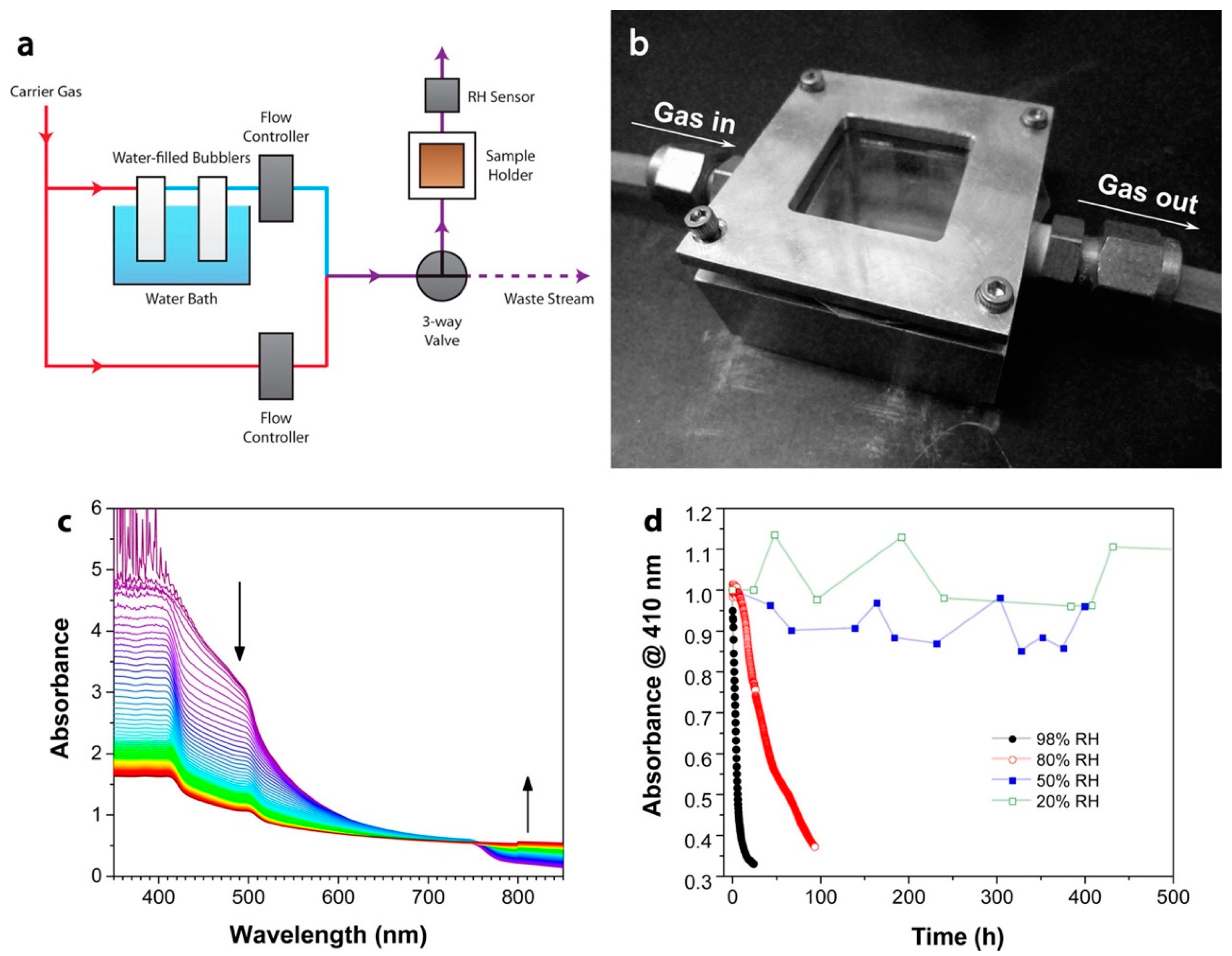
Table 1.
The performance of cells with different designs in combination with liquid and solid-state electrolytes using different electrodes.
Table 1.
The performance of cells with different designs in combination with liquid and solid-state electrolytes using different electrodes.
| Cell Type | Dye | Photoanode/ Cathode | Electrolyte | CE | VOC (V) | JSC (mAcm−2) | FF | η (%) | Refs. |
|---|---|---|---|---|---|---|---|---|---|
| Wine Daisy flower petals | Anthocyanin (Lv) | TiO2/ITO | I−/I3− | Graphite C/ITO | 0.52 | 0.38 | 0.26 | 0.79 | [89] |
| Wine Daisy flower petals | Anthocyanin (Lv) | TiO2/ITO | I−/I3− | Pt/ITO | 0.52 | 0.42 | 0.27 | 0.87 | [89] |
| Ru (II) complexes bearing diamine-based bidentate ligands | Ru (II) 8A | TiO2/FTO | I−/I3− | Pt/FTO | 0.64 | 5.13 | 0.68 | 2.25 | [90] |
| Co-additive CDA | N719 + 7.5 mM CDA | TiO2/FTO | I−/I3− | Graphite C- PEDOT: PSS/FT O | 0.79 | 11.64 | 0.76 | 7.00 | [91] |
| Co-additive CDA | RhB + 10 mM CDA | TiO2/FTO | I−/I3− | Graphite C- PEDOT: PSS/FT O | 0.61 | 4.19 | 0.69 | 1.75 | [91] |
| Co-additive CDA | D149 + 10 mM CDA | TiO2/FTO | I−/I3− | Graphite C- PEDOT: PSS/FT O | 0.81 | 13.77 | 0.69 | 7.72 | [91] |
| TiO2/ZnO Blocking Layer | N719 | TiO2 NP/TiO2/ZnO/FTO | I−/I3− | Pt/FTO | 0.73 | 16.63 | 0.59 | 7.10 | [92] |
| 2- cyanoacetani lide based organic dyes | Ru (II) complex HD-2 with SA1 | TiO2/FTO | I−/I3− | Pt/FTO | 0.68 | 20.33 | 0.58 | 8.02 | [93] |
| Catecholpyr ano-5,7,3′,4′-tetrahydroxy flavylium pyranoflavyli um salts | Pyrano- anthocyanin | TiO2/FTO | I−/I3− | Pt/FTO | 0.34 | 6.43 | 0.53 | 1.15 | [94] |
| Natural liquid dye extract 12- hour immersion | PIW Leaf chlorophyll | TiO2/ITO | I−/I3− | Candle soot C/ITO | 0.42 | 0.14 | 0.41 | 0.02 | [95] |
| Screen printing 0.25 cm2 | D35 | TiO2 NP/FTO | I−/I3− | Pt/FTO | 0.76 | 10.03 | 0.72 | 5.48 | [96] |
| Digital printing 0.25 cm2 | D35 | TiO2 NP/FTO | I−/I3− | Pt/FTO | 0.78 | 12.65 | 0.75 | 7.40 | [96] |
| (D–A–π–A) type zinc porphyrin sensitizers | TH-2F | TiO2/FTO | 0.1 M TBAPF6 | Pt/FTO | 0.68 | 16.07 | 0.64 | 6.98 | [97] |
| Gel polymer electrolyte based DSSCs | Black mulberry fruits juice | TiO2/FTO | AMPS-IA-F-Cl-Br- An | Pt/FTO | 0.40 | 0.02 | 0.49 | [98] | |
| Combination of natural red and green dyes | 80% R +20% G | TiO2/FTO | I−/I3− | C (CNT)/F TO | 0.30 | 4.65 | 0.55 | 0.99 | [99] |
| Mixed one layer Pigment combination | Chlorophyll and anthocyanin volumetric proportion of 1:1 | TiO2/FTO | I−/I3− | Pt/FTO | 0.72 | 1.61 | 0.73 | 0.85 | [100] |
| Two distinct layer Pigment combination | Chlorophyll and anthocyanin volumetric proportion of 1:1 | TiO2/FTO | I−/I3− | Pt/FTO | 0.71 | 1.38 | 0.74 | 0.74 | [100] |
Table 2.
Properties of perovskite materials.
| Properties | Value Range |
|---|---|
| Bandgap | 1.5–2.5 eV |
| Exciton binding energy | Less than 10 meV |
| Crystallization energy barrier | 56.6–97.3 kJ mol−1 |
| Relative permittivity | 3 |
| Charge carrier lifetime | Greater than 300 nm |
| PL quantum efficiency | 70% |
| Trap-state density | 1010 cm3 (single crystals), 1015–1017 cm3 (polycrystalline) |
| Carrier mobility | 800 cm2/Vs |
Table 3.
Additives employed in PSCs to enhance device performance (PCE).
| Perovskite Composition | Additive Name | VOC (V) | JSC (mA cm−2) | FF (%) | η (%) | Additive (%) | Refs. |
|---|---|---|---|---|---|---|---|
| MAPbI3 | ammonium benzenesulfonate | 1.09 | 22.92 | 78.62 | 17.29 | 19.64 | [130] |
| MAPbI3 | 1-alkyl-4-amino-1,2,4-triazolium | 1.10 | 23.39 | 77.84 | 16.13 | 20.03 | [131] |
| MAPbI3 | dibutylhydroxytoluene | 1.03 | 22.50 | 78.10 | 17.10 | 18.10 | [132] |
| MAPbI3 | pyrrole | 1.142 | 23.38 | 75.20 | 18.58 | 20.07 | [133] |
| Cs0.05(FA0.85MA0.15)0.95Pb(I0.85Br0.15)3 | 1-propionate-4-amino-1,2,4-triazolium tetrafluoroborate (PATMBF4) | 1.11 | 23.74 | 81.02 | 18.27 | 21.35 | [134] |
| Cs0.05(MA0.12FA0.88)0.95Pb(I0·88Br0.12)3 | 6-aminoquinoline monohydrochloride (AQCl) | 1.18 | 22.74 | 80.73 | 19.24 | 21.66 | [135] |
| CH3NH3PbI3 | carbon quantum dots(A-CQDs) | 0.94 | 22.35 | 51.27 | 9.15 | 10.74 | [136] |
| CsPbI3 | bis(pentafluorophenyl)zinc [Zn(C6F5)2] | 1.12 | 20.67 | 81.98 | 16.97 | 19.00 | [137] |
| CsPbI2Br | 2-hydroxyethyl methacrylate (HEMA) | 1.23 | 15.81 | 82.98 | 14.10 | 16.13 | [138] |
| CsPbI3 | ethanol/MACl (Et-M) | 0.928 | 20.75 | 68.43 | 9.49 | 13.18 | [139] |
Table 4.
Optimization of transmission materials in PSCs to enhance device performance (PCE).
| Perovskite Composition | Transmission Material | VOC (V) | JSC (mA cm−2) | FF (%) | η (%) | Refs. |
|---|---|---|---|---|---|---|
| Cs0.05(FA0.85MA0.15)0.95Pb(Br0.15I0.85)3 | ZTO-ZnS(ETL) | 1.15 | 23.80 | 77.70 | 21.30 | [143] |
| CsFAMA | MPA-BTTI(HTL) | 1.12 | 23.23 | 81.40 | 21.17 | [144] |
| CH3NH3PbI3 | 2,3-bis(4′-(bis(4-methoxyphenyl)amino)-[1,1′-biphenyl]-4-yl)fumaronitrile(TPA-BPFN-TPA)(HTL) | 1.04 | 22.70 | 78.00 | 18.40 | [145] |
| CsPbBr3 | Nb2O5 (a-Nb2O5)(ETL) | 1.45 | 5.64 | 70.00 | 5.74 | [146] |
| Cs0.05(FA0.85MA0.15)0.95Pb(I0.85Br0.15)3 | Cu2OCuSCN nanocomposite (HTL) | 1.05 | 23.23 | 78.40 | 19.20 | [147] |
| CH3NH3PbI3 | BaTiO3/TiO2 (ETL) | 0.97 | 20.50 | 65.00 | 13.00 | [148] |
| (FAPbI3)0.85(MAPbBr3)0.15 | 3,6-N(HTL) | 1.08 | 22.65 | 78.00 | 19.25 | [149] |
| Cs0.05(MA0.13FA0.87)0.95Pb(I0.87Br0.13)3 | PdPrPc(HTL) | 1.08 | 23.49 | 71.11 | 18.09 | [150] |
| (CsPbI3)0.05(FA0.85MA0.15Pb[I0.85Br0.15]3)0.95 | NH2-ZnO@SnO2(ETL) | 1.14 | 25.11 | 78.68 | 22.52 | [151] |
| CsPbIBr2 | In2S3(ETL) | 1.09 | 7.76 | 65.94 | 5.59 | [152] |
Table 5.
Interface modification employed in PSCs to enhance device performance (PCE).
| Device Structure | VOC (V) | JSC (mA cm−2) | FF (%) | η (%) | Refs. |
|---|---|---|---|---|---|
| FTO/TiO2/perovskite/(Me-PDA)Pb2I6/Spiro-OMETAD/Au | 1.13 | 24.61 | 79.00 | 22.00 | [155] |
| FTO/PCBM/perovskite/Spiro-OMETAD/Au | 1.12 | 22.77 | 79.00 | 20.12 | [156] |
| ITO/SnO2/perovskite/PTAA/Metal | 1.11 | 24.06 | 75.81 | 20.30 | [157] |
| ITO/NiOx/PTAA/(MAPbI3)0.95(MAPbBr2Cl)0.05/PCBM/BCP/Ag | 1.19 | 22.23 | 81.71 | 21.56 | [158] |
| FTO/c-TiO2/perovskite/PTABr/PTAA:LAD/Au | 1.09 | 23.28 | 79.13 | 20.13 | [159] |
| FTO/bl-RiO2/MAPbI3/PbS/Spiro-OMETAD/Au | 1.14 | 23.17 | 72.83 | 19.24 | [160] |
| ITO/SnO2/MAPbI3/4-CIBA Spiro-OMETAD/Ag | 1.16 | 22.76 | 74.00 | 20.99 | [161] |
| FTO/SnO2/BCP/Spiro-OMETAD/Ag | 1.14 | 23.50 | 77.10 | 20.60 | [162] |
Table 6.
Photovoltaic parameters of QDSCs based on different photoanodes.
| Photoanodes | Sensitizer | VOC (V) | JSC (mA/cm2) | FF | η (%) | Refs. |
|---|---|---|---|---|---|---|
| TiO2 | CdS | 0.37 | 6.24 | 0.33 | 0.75 | [216] |
| TiO2 | CdSeS | 0.68 | 16.8 | 0.44 | 5.01 | [217] |
| TiO2 | ZCISe | 0.59 | 11.58 | 0.63 | 4.25 | [218] |
| TiO2 | CdS/CdSe | 0.53 | 12.5 | 0.60 | 3.96 | [219] |
| TiO2 | CdSe/CdS | 0.62 | 14.4 | 0.49 | 4.41 | [220] |
| TiO2 | CdS/CdSe | 0.56 | 16.1 | 0.337 | 3.06 | [221] |
| TiO2 | CsPbI3 | 1.20 | 14.37 | 0.78 | 13.4 | [222] |
| TiO2 | PbS | 0.59 | 8.92 | 0.56 | 2.94 | [204] |
| TiO2 | PbS | 0.52 | 18.14 | 0.46 | 4.4 | [223] |
| TiO2 | PbSe | 0.52 | 23.4 | 0.52 | 6.2 | [224] |
| TiO2 | PbSe | 0.53 | 24 | 0.51 | 6.47 | [225] |
| TiO2 | CdS/CdSe: Mn (2%) | 0.56 | 20.7 | 0.47 | 5.42 | [226] |
| TiO2 | CdS: Graphene (1.6%) | 0.54 | 5.9 | 0.38 | 1.2 | [227] |
| TiO2 NF | CdSe | 0.42 | 9.21 | 0.56 | 2.15 | [228] |
| TiO2 NFs | CZTSe | 0.47 | 13.65 | 0.56 | 3.61 | [229] |
| TiO2 NFs | Ag2Se | 0.41 | 11.12 | 0.55 | 2.5 | [230] |
| TiO2/C– TiO2/TiO2 | CdS | 0.27 | 4.80 | 0.13 | 0.17 | [208] |
| TiO2/QD/TiCl4 | CdSeTe | 0.70 | 20.69 | 0.62 | 9.01 | [231] |
| TiO2/ZnO NR why different? | CdS | 0.41 | 2.37 | 0.35 | 0.33 | [232] |
| TiO2/ZnO NR | CdS | 0.48 | 13.34 | 0.42 | 2.71 | |
| TiO2: B/Sa co-doped | CdS | 1.22 | 3.35 | 0.88 | 3.60 | [233] |
| TiO2:TiCl4 | CdSe | 0.56 | 15.54 | 0.61 | 5.53 | [234] |
| TiO2wth SrTiO3 (10%) | CdS | 0.60 | 6 | 0.48 | 1.80 | [235] |
| N doped TiO2 | CdS | 0.84 | 10.40 | 0.53 | 4.58 | [236] |
| P– TiO2 NF | Cu2AgInSe4 (CAISe) | 0.52 | 12.86 | 0.63 | 4.24 | [237] |
| BaTiO3 | CdS | 0.61 | 3.74 | 0.56 | 1.26 | [238] |
| NiO | CuInSxSe2−x:Zn+2 | 0.35 | 9.13 | 0.39 | 1.25 | [211] |
| SnO2 | CdS | 0.45 | 1.47 | 0.34 | 0.22 | [210] |
| SnO2 NF | CdS | 0.61 | 11.56 | 0.43 | 3 | [239] |
| SnO2 with TiCl4 | PbS/CdS | 0.30 | 19.12 | 0.28 | 1.60 | [240] |
| ZnO | CdS/CdSe | 0.67 | 4.77 | 0.39 | 1.26 | [241] |
| ZnO | PbS-TBAI /PbS-EDT | 24.2 | 0.55 | 0.64 | 8.55 | [242] |
| ZnO | CdS/CdSe | 0.61 | 9.93 | 0.52 | 3.14 | [243] |
| ZnO | CdS/CdSe | 0.68 | 10.48 | 0.62 | 4.46 | [244] |
| ZnO (Al doped) | CdS/CdSe | 0.60 | 12.86 | 0.69 | 5.32 | [209] |
| ZnO NP | CdS/CdSe | 0.50 | 15.40 | 0.44 | 3.35 | [245] |
| ZnO/TiO2 | CdS | 0.46 | 7.80 | 0.68 | 2.44 | [246] |
| ZnTi | CdS | 0.63 | 10.14 | 0.61 | 3.92 | [247] |
| ZnTiO3 | CdS/CdSe | 0.59 | 5.96 | 0.56 | 1.95 | [248] |
Table 7.
Efficiency details of QDSCs based on different QDs.
| QD Sensitizer | Photoanode | Counter Electrodes | η (%) | Refs. |
|---|---|---|---|---|
| CdSe/CdS | TiO2 | Au | 4.8 | [269] |
| CdSe | TiO2–SeO2 | CoS2 | 3.45 | [270] |
| PbS/CdS/CdSe | TiO2 | CuS | 4.58 | [271] |
| CdSe | TiO2 | Cu2S | 2 | [272] |
| CdSe | TiO2 | Pt-coated FTO | 1.7 | [273] |
| CdSe | TiO2: Mg+2 | Cu2S/brass | 6.9 | [274] |
| Zn–Cu–In–Se (ZCISe) | TiO2: Mg+2 | Cu2S/brass | 9.02 | |
| CdS | TiO2 | CuS/PbS | 1.13 | [253] |
| PbS/CdS | TiO2 | CuS/PbS | 1.84 | |
| CdSe | TiO2 | CuS/PbS | 2.84 | |
| CdS/CdSe | TiO2 | CuS/PbS | 3.63 | |
| CdTe/CdS | TiO2 | CuSNP | 2.5 | [249] |
| PbS CQD with PBDB-T(F) | ZnO | MoO3/Ag | 11.2 | [255] |
| PbSE CQD | SnO2 | Au | 10.4 | [250] |
| CIS–CuInS2 | TiO2 | Au | 0.75 | [258] |
| CdS–Bi2S3 | TiO2 | CuI | 1.01 | [257] |
| CuBiS2 | TiO2 | Cu2S | 0.62 | [260] |
| CdS/CdSe | ZnTi MMO | Cu2S | 2.85 | [266] |
| CdS/Ag2S–ZnS | TiO2 | CuS | 3 | [262] |
| Bi2S3/Sb2S3 | TiO2 | Pt | 0.67 | [263] |
| ZnS coated InP | TiO2 | Brass | 0.351 | [268] |
| Cd1-XZnXTe/CdS | TiO2 | Cu2S | 3.27 | [261] |
| Co+2 (3%) doped CdS | TiO2 | Pt | 1.21 | [275] |
| Mn+2 doped CdS | ZnO | Al | 2.09 | [276] |
| PbS:Hg | TiO2 (NP/NF) | Cu2S | 4.72 | [277] |
| CdSe:Ag+ | TiO2 | Cu2S | 2.72 | [278] |
| Cu–CdS | TiO2 | Pt | 1.04 | [279] |
| In–CdS | TiO2 | Pt | 0.65 | |
| Mg-doped CdSe | TiO2 | Pt-ITO | 0.67 | [280] |
| CdS/CdSe | TiO2 (NCs) | CuS | 6.80 | [281] |
| CdS/CdSe | TiO2 | CuS | 5.07 | [282] |
| PbS | ZnO | Au | 9.40 | [283] |
| Gradient-band-gap PbS | TiO2 | – | 4.08 | [284] |
| CdS | TiO2 | Au | 0.80 | [285] |
| CdS/CdSe/ZnS | TiO2 | CoO | 6.02 | [286] |
| CdTe/CdS | TiO2 | Cu2S | 2.44 | [287] |
| CIS-Z and (CuInS2 (CIS) QDs) | TiO2 | Cu2S on brass foil | 7.04 | [288] |
| CIS | TiO2 | Cu2S on brass foil | 5.05 | |
| CuInSexS2−x | TiO2 | CuS | 5.51 | [289] |
| ZCISe | TiO2 | MC/Ti | 12.65 | [290] |
| ZCISe/ZnSe | TiO2 | MC/Ti | 13.84 | |
| CISe | TiO2 | Cu2S/brass | 7.56 | [291] |
| CIGSe | TiO2 | Cu2S/brass | 9.30 | |
| CISe | TiO2 | MC/Ti | 9.18 | |
| CIGSe | TiO2 | MC/Ti | 11.30 | |
| Cu2ZnSnS4 (CZTS) | TiO2 | Cu2S | 3.29 | [292] |
| CAIS(Cu2AgInS4) | TiO2 | Cu2S/FTO | 4.89 | [293] |
| ZCISSe | TiO2 | – | 14.70 | [294] |
| N2-CQDs | TiO2 | Pt | 0.45 | [295] |
| CAISe (Cu2AgInSe4) | TiO2 | Cu2S | 4.24 | [236] |
Table 8.
Details of QDs as additives in ETLs.
| QDs | Device Structure | VOC (V) | JSC (mA cm−2) | FF (%) | η (%) | Refs. |
|---|---|---|---|---|---|---|
| CQDs | FTO/c-TiO2/m-TiO2:CQDs/MAPbClxI3−x/Spiro-OMeTAD/Au | 1.02 | 22.64 | 71.6 | 16.40 | [303] |
| CQDs | ITO/TiO2:CQDs/MAPbI3Cl3−x/Spiro-OMeTAD/Au | 1.14 | 21.36 | 78 | 18.89 | [304] |
| CQDs | FTO/PEDOT:PSS/MAPbI3/PCBM:CQDs/BCP/Ag | 0.97 | 22.30 | 79.6 | 18.10 | [305] |
| g-C3N4 QDs | ITO/SnO2:g-C3N4 QDs/CsFAMA/Spiro-OMeTAD/Au | 1.18 | 24.03 | 78.3 | 22.13 | [306] |
| Red CQDs | ITO/SnO2:RCQs/Cs0.05FA0.81MA0.14PbI2.25Br0.45/Spiro-OMeTAD/MoO3/Au | 1.14 | 24.1 | 82.9 | 22.77 | [307] |
| GQDs | FTO/Au/SnO2:GQDs/ZnO/Perovskite/Spiro-OMeTAD/Au | 1.17 | 22.85 | 74 | 19.81 | [308] |
| GQDs | ITO/SnO2:GQDs/MAPbI3/Spiro-OMeTAD/Au | 1.13 | 23.05 | 78 | 20.31 | [309] |
| GQDs | FTO/SnO2:GQDs/CsFAMA/Spiro-OMeTAD/Ag | 1.10 | 21.62 | 78 | 18.55 | [310] |
| GQDs | ITO/c-TiO2/m-TiO2:GQDs/Cs0.05(MA0.17FA0.83)0.95Pb(I0.83Br0.17)3/Spiro-OMeTAD/Au | 0.97 | 21.92 | 67 | 14.36 | [311] |
| GQDs | ITO/PCBM:GQDs/MAPbI3/Spiro-OMeTAD/Au | 1.09 | 22.03 | 73 | 17.56 | [312] |
| GQDs | ITO/SnO2:GQDs/MAFAPbIxCl3−x/Spiro-OMeTAD/Ag | 1.11 | 24.40 | 78 | 21.10 | [313] |
| QDs | FTO/c-TiO2/m-TiO2:GQDs/Perovskite/Spiro-OMeTAD/Ag | 1.08 | 24.92 | 76 | 20.45 | [314] |
| GQDs | FTO/SnO2:GQDs/CsFAMA/Spiro-OMeTAD/Au | 1.08 | 23.5 | 77 | 19.6 | [315] |
| CdSe QDs | ITO/PEDOT:PSS/CH3NH3PbI3−xClx/PCBM:CdSe QDs/LiF/Ag | 0.90 | 20.96 | 73.16 | 13.73 | [316] |
| CdS QDs | FTO/TiO2:CdS QDs/CH3NH3PbI3/Spiro-OMeTAD/Au | 0.94 | 16.7 | 64 | 10.52 | [317] |
| PbS QDs | FTO/TNTs:PbS QDs/Cs0.05(FA0.85MA0.15)0.95Pb(I0.85Br0.15)3/Spiro-OMeTAD/Au | 1.14 | 23.38 | 56.03 | 14.95 | [318] |
| PbS QDs | ITO/ZnO:PbS QDs-TBAI-80/MAPbI3/PCBM/Ag | 1.14 | 22.80 | 78.99 | 20.53 | [319] |
| BP QDs | Glass/FTO/SnO2:BP QDs/BP QDs@A-CsFAMA/Spiro-OMeTAD/Ag | 1.22 | 23.53 | 79.6 | 22.85 | [320] |
| BP QDs | FTO/SnO2:BP QDs/(FAPbI3)0.97(MAPbBr3)0.03/Spiro-OMeTAD/Ag | 1.13 | 24.4 | 76.1 | 21.0 | [321] |
| SnO2 QDs | FTO/c-TiO2/m-TiO2:SnO2 QDs/MAPbI3/Spiro-OMeTAD/Ag | 1.13 | 22.36 | 75.67 | 19.09 | [322] |
Table 9.
Details of QDs as additives in HTLs.
| QDs | Device Structure | VOC (V) | JSC (mA cm−2) | FF (%) | η (%) | Refs. |
|---|---|---|---|---|---|---|
| CQDs | FTO/SnO2/(FAPbI3)0.95(MAPbBr3)0.05/Spiro-OMeTAD:GQDs/Ag | 1.06 | 24.17 | 79.41 | 20.41 | [323] |
| CQDs | ITO/GO:CQDs/CH3NH3PbI3/PCBM/BCP/Ag | 0.95 | 21.0 | 80.1 | 16.2 | [324] |
| CQDs | ITO/NiO:CQDs/CH3NH3PbI3/PCBM/BCP/Ag | 1.08 | 20.22 | 77.15 | 16.91 | [325] |
| GQDs | FTO/PEDOT:PSS/GQDs/CH3NH3PbI3/PCBM/BCP/Ag | 1.00 | 21.41 | 75.31 | 16.16 | [326] |
| AGQDs | ITO/NiO:AGQDs/(FA0.83MA0.17)0.95Cs0.05Pb(I0.9Br0.1)3/PCBM/BCP/Ag | 1.07 | 22.5 | 81.5 | 19.55 | [327] |
| Graphdiyne QDs | FTO/TiO2/GD QDs/CH3NH3PbI3:GD QDs/Spiro-OMeTAD:GD QDs/Au | 1.12 | 22.48 | 78.7 | 19.89 | [328] |
| Graphdiyne QDs | FTO/TiO2/CH3NH3PbI3/P3HT:GD QDs/Au | 0.94 | 21.7 | 71.3 | 14.58 | [329] |
| PbSO4(PbO)4 QDs | ITO/SnO2/CsFAMA/Spiro-OMeTAD:PbSO4(PbO)4 QDs/Au | 1.14 | 24.80 | 80 | 22.66 | [330] |
Table 10.
Details of QDs as ETMs.
| QDs | Device Structure | VOC (V) | JSC (mA cm−2) | FF (%) | η (%) | Refs. |
|---|---|---|---|---|---|---|
| ZnO QDs | ITO-PET/Graphene/ZnO QDs (Apjet)/CH3NH3PbI3/Spiro-OMeTAD/Ag | 0.94 | 16.80 | 62 | 9.73 | [331] |
| ZnO/rGO QDs | FTO/ZnO/rGO QDs/CH3NH3PbI3/Spiro-OMeTAD/Au | 1.03 | 21.7 | 68 | 15.2 | [332] |
| TiO2 QDs | FTO/TiO2 QDs/m-TiO2/CH3NH3PbI3/Spiro-OMeTAD/Au | 1.06 | 22.48 | 71 | 16.97 | [333] |
| SnO2 QDs | ITO/SnO2 QDs/MAPbI3/Spiro-OMeTAD/Ag | 1.08 | 21.85 | 74.28 | 17.66 | [334] |
| SnO2 QDs | FTO/SnO2 QDs/MA0.7FA0.3PbI3/Spiro-OMeTAD/Au | 1.08 | 23.40 | 74 | 20.1 | [335] |
| SnO2 QDs | FTO/Al:SnO2 QDs/MAPbI3/Spiro-OMeTAD/Ag | 1.06 | 22.78 | 75.41 | 18.20 | [336] |
| SnO2 QDs | FTO/SnO2 QDs/Cs0.05(MA0.17FA0.83)0.95Pb(I0.83Br0.17)3/Spiro-OMeTAD/Ag | 1.13 | 23.05 | 79.8 | 20.79 | [337] |
| SnO2 QDs | ITO/SnO2 QDs/MAPbI3/Li-doped Spiro-OMeTAD/Au | 1.12 | 21.61 | 77 | 18.71 | [338] |
| SnO2 QDs | ITO/SnO2 QDs/Cs0.05FA0.81MA0.14PbI2.25Br0.45/Spiro-OMeTAD/Carbon | 1.08 | 22.19 | 56.64 | 13.64 | [339] |
| BP QDs | ITO-PEN/BP QDs/FA0.85MA0.15PbI0.25Br0.5/Spiro-OMeTAD/Au | 1.03 | 16.77 | 65.2 | 11.26 | [340] |
Table 11.
Details of QDs as HTMs. Reproduced with permission from MDPI.
| QDs | Device Structure | VOC (V) | JSC (mA cm−2) | FF (%) | η (%) | Refs. |
|---|---|---|---|---|---|---|
| PbS QDs | ITO/PbS QDs/MAPbI3/PCBM/Al | 0.86 | 12.10 | 72 | 7.5 | [341] |
| PbS QDs | FTO/c-TiO2/m-TiO2/CH3NH3PbI3/PbS QDs/Au | 0.87 | 18.69 | 49 | 7.88 | [342] |
| CQDs | FTO/c-TiO2/m-TiO2/MAPbI3/CQDs/Au | 0.52 | 7.83 | 74 | 3 | [343] |
| PbS QDs | FTO/c-TiO2/m-TiO2/CH3NH3PbI3/PbS QDs/Au | 0.97 | 19.03 | 61.34 | 11.32 | [344] |
| PbS QDs | FTO/TiO2/m-TiO2/CH3NH3PbI3/PbS QDs/Au | 0.80 | 29.3 | 83 | 19.52 | [345] |
| CuInS2 QDs | FTO/c-TiO2/m-TiO2/MAPbI3/CuInS2/ZnS QDs/Au | 0.92 | 18.6 | 48.7 | 8.38 | [346] |
| CuIn1.5Se3 QDs | ITO/SnO2/MAPbBr3/CuIn1.5Se3 QDs/Au | 0.98 | 20.46 | 68.5 | 13.72 | [347] |
| CuInSe2 QDs | ITO/SnO2/FAMAPbI3BrCl/CuInSe2 QDs/Au | 0.86 | 22.5 | 66 | 12.8 | [348] |
| SnS QDs | FTO/c-TiO2/(CsPbI3)0.05(FAPbI3)0.79(MAPbI3)0.16/SnS QDsn/Au | 0.94 | 22.96 | 63.3 | 13.72 | [349] |
| MoS2 QDs | FTO/c-TiO2/m-TiO2/CsPbBr3/MoS2 QDs/Carbon | 1.31 | 6.55 | 79.4 | 6.80 | [350] |
| Cu2O QDs | FTO/c-TiO2/m-TiO2/Cs0.05FA0.81MA0.14PbI2.55Br0.45/Cu2O QDs/Au | 1.15 | 22.2 | 74.2 | 18.90 | [351] |
| CsSnBr3 QDs | FTO/SnO2 QDs/CsPbBr3/CsSnBr3 QDs/Carbon | 1.61 | 7.8 | 84.4 | 10.60 | [352] |
| Ag-In-Ga-S QDs | FTO/c-TiO2/m-TiO2/CsPbBr3/AIGS QDs/Carbon | 1.46 | 7.43 | 80.31 | 8.46 | [353] |
| Cu12Sb4S13 QDs | FTO/c-TiO2/CH3NH3PbI3/Cu12Sb4S13 QDs/Au | 1.05 | 21.85 | 61.6 | 14.13 | [354] |
| Cu12Sb4S13 QDS | FTO/c-TiO2/m-TiO2/CsPbI3 QDs/Cu12Sb4S13 QDs/Au | 1.04 | 18.28 | 52.9 | 10.02 | [355] |
| Cu12Sb4S13 QDs | FTO/c-TiO2/CH3NH3PbI3/Cu12Sb4S13 QDs/Au | 0.80 | 18.08 | 45 | 6.50 | [356] |
| Cu2ZnSnS4 QDs | FTO/c-TiO2/CH3NH3PbI3/Cu2ZnSnS4 QDs/Au | 1.06 | 20.54 | 58.7 | 12.75 | [357] |
| Cu2ZnSnS4 QDs | FTO/m-TiO2/c-TiO2/CsPbBr3/Cu2ZnSnS4 QDs/Ag | 0.94 | 7.36 | 70.01 | 4.84 | [358] |
| Cu2ZnSnS4 QDs | ITO/Cu2ZnSnS4-LF QDs/Perovskite/PCBM/Ag | 0.92 | 20.7 | 81 | 15.40 | [359] |
| Cu2ZnSnSe4 QDs | FTO/TiO2/CH3NH3PbI3/Cu2ZnSnSe4 QDs/Au | 0.81 | 19.37 | 62.1 | 9.72 | [360] |
| CuIn0.1Ga0.9(S0.9Se0.1)2 QDs | FTO/c-TiO2/m-TiO2/CH3NH3PbI3/CIGSSe QDs/Au | 0.94 | 17.66 | 54.88 | 9.15 | [361] |
| CsSnBr2I QDs | FTO/c-TiO2/m-TiO2/CsPbBr3/CsSnBr2I QDs/Carbon | 1.39 | 8.70 | 76 | 9.13 | [362] |
Table 12.
ETMs used for different configurations of tandem cells.
| Top Cell (TC) | Bottom Cell (BC) | ETL | VOC (V) | JSC (mA cm−2) | FF (%) | Area (cm2) | η (%) | T.C η (%) | B.C η (%) | Refs. |
|---|---|---|---|---|---|---|---|---|---|---|
| CH3NH3PbI3 | C-Si | C60 | – | – | – | – | 24.6 | 16.23 | 8.37 | [376] |
| CsFAMA | n-Si | SnO2 | – | 39.50 | – | – | 28.2 | 19.00 | 24.00 | [377] |
| (MAPb(I0.95 Br 0.05)3 | C-Si | PCBM/Z nO | 1.67 | 18.29 | 77.00 | – | 23.50 | – | – | [378] |
| FA0.83Cs0.17 Pb(I0.80Br0.20)3 | C-Si | SnO2- LiCl | 1.90 | 16.90 | 77.90 | 0.50 | 25.40 | – | – | [379] |
| Cs0.05MA0.15FA0.8Pb(I0.85Br0.15)3 | C-Si | C60 Anchored /a-NbOx | 1.80 | 19.50 | 75.90 | – | 27 | – | – | [380] |
| CsFAMABrI | C-Si | TiO2 | 1.80 | 18.81 | 75.60 | 1.20 | 26.30 | – | – | [381] |
| CsMAPbBr | C-Si | C60 | 1.82 | 19.20 | 74.40 | – | 26 | – | – | [382] |
| CH3NH3PbI3 | p-Si | ZnO | 1.77 | 20.19 | 82.22 | – | 28.50 | – | – | [383] |
Table 13.
HTMs utilized for various configurations of tandem cells.
| TC | BC | HTL | Configuration | VOC (V) | JSC (mA cm−2) | FF (%) | Area (cm2) | η (%) | T.C η (%) | B.C η (%) | Refs. |
|---|---|---|---|---|---|---|---|---|---|---|---|
| CH3NH3PbI3 | C-Si | Spiro- OMeTAD | p-i-n | – | – | – | 23.70 | – | – | [384] | |
| (FAPbI3)0.95 (MAPbBr3)0.05 | P-Si | PTAA | p-i-n | 0.65 | 13.50 | 80.10 | – | 26.0 | 18.90 | 7.10 | [385] |
| (Cs0.05(FA0.83 MA0.17)0.95 Pb(I0.83 Br 0.17)3) | C-Si | Spiro- OMeTAD | n-i-p | – | – | – | – | 17.10 | 11.70 | 5.40 | [386] |
| CsmFAnMA1- m-nPbIxBr3-x | C-Si | NiOx/poly- TPD | p-i-n | 1.88 | 19.12 | 75.30 | 1 | 27.00 | – | – | [387] |
| Cs0.05(FA0.83 MA0.17)0.95 Pb(I0.8Br0.2)3 | C-Si | Poly TPD and NPD | p-i-n | 1.74 | 17.93 | 74.31 | – | 25.20 | – | – | [388] |
| CH3NH3PbI3 | C-Si | PEDOT: PSS | n-i-p | 1.78 | 14.70 | 80.40 | – | 21 | – | – | [389] |
Table 14.
Features of small molecule NFAs and respective devices performances.
| Acceptor | HOMO/LUMO (eV) | Donor | JSC (mA/cm2) | VOC (V) | FF (%) | PCE (%) | Refs. |
|---|---|---|---|---|---|---|---|
| ITIC | −5.48/−3.83 | PTB7-Th | 14.21 | 0.81 | 59.1 | 6.80 | [409] |
| ITIC | −5.51/−3.78 | PBDB-T | 16.81 | 0.899 | 74.2 | 11.21 | [419] |
| ITIC | −5.48/−3.83 | PBDTS-TDZ | 17.78 | 1.10 | 65.4 | 12.80 | [420] |
| ITIC-Th | −5.66/−3.93 | PDBT-T1 | 16.24 | 0.88 | 67.1 | 9.6 | [421] |
| IT-M | −5.58/−3.98 | PBDB-T | 17.44 | 0.94 | 73.5 | 12.05 | [422] |
| IT-4F | −5.66/−4.14 | PBDB-T-SF | 20.50 | 0.88 | 71.9 | 12.97 | [410] |
| SeTIC4Cl | −5.65/−4.08 | PM6 | 22.92 | 0.78 | 75 | 13.32 | [423] |
| IDIC | −5.7/−3.9 | FTAZ | 20.8 | 0.84 | 71.8 | 12.5 | [424] |
| IOIC3 | −5.38/−3.84 | PTB7-Th | 22.9 | 0.762 | 74.9 | 13.1 | [425] |
| FOIC | −5.36/−3.92 | PTB7-Th | 24.0 | 0.743 | 67.1 | 12.0 | [426] |
| Y6 | −5.65/−4.10 | PM6 | 25.2 | 0.82 | 76.1 | 15.7 | [411] |
| Y6 | −5.7/−4.1 | PM6 | 27.43 | 0.845 | 73.8 | 17.1 | [427] |
| Y6 | −5.65/−4.10 | D18 | 27.70 | 0.859 | 76.6 | 18.22 | [403] |
| BTP-4Cl | −5.65/−4.02 | PM6 | 25.4 | 0.867 | 75 | 16.5 | [428] |
| BTP-eC9 | −5.64/−4.05 | PM6 | 26.2 | 0.839 | 81.1 | 17.8 | [429] |
| Y6Se | −5.70/−4.15 | D18 | 27.98 | 0.839 | 75.3 | 17.7 | [430] |
| m-BTP-PhC6 | −5.51/−3.46 | PTQ10 | 25.3 | 0.883 | 79.3 | 17.7 | [431] |
| L8-BO | −5.68/−3.90 | PM6 | 25.72 | 0.87 | 81.5 | 18.32 | [432] |
| L8-BO | -/- | PM6 | 26.03 | 0.893 | 80.0 | 18.60 | [433] |
Table 15.
Features of small molecule NFAs and respective devices performances.
| Donor | HOMO/LUMO (eV) | Acceptor | JSC (mA/cm2) | VOC (V) | FF (%) | PCE (%) | Refs. |
|---|---|---|---|---|---|---|---|
| PDBT-T1 | −5.36/−3.43 | ITIC-Th | 16.24 | 0.88 | 67.1 | 9.6 | [421] |
| PBDB-T | −5.33/−2.92 | ITIC | 16.81 | 0.899 | 74.2 | 11.21 | [419] |
| PBDB-T | −5.39/−3.50 | Y1 | 22.44 | 0.87 | 69.1 | 13.42 | [436] |
| PBDB-T-SF | −5.40/−3.60 | IT-4F | 20.88 | 0.88 | 71.3 | 13.10 | [410] |
| PBDB-T-2F (PM6) | −5.47/- | IT-4F | 20.81 | 0.84 | 76 | 13.2 | [437] |
| PM6 | −5.56/−3.50 | Y6 | 25.2 | 0.82 | 76.1 | 15.7 | [411] |
| PM6 | −5.47/−3.56 | BTP-eC9 | 26.2 | 0.839 | 81.1 | 17.8 | [429] |
| PBDB-T-2Cl (PM7) | −5.51/- | IT-4F | 21.80 | 0.86 | 77 | 14.4 | [436] |
| PM7 | −5.52/−3.57 | Y6 | 25.644 | 0.897 | 74.0 | 17.037 | [437] |
| T1 | −5.48/−3.63 | IT-4F | 21.5 | 0.899 | 78 | 15.1 | [438] |
| J61 | −5.32/−3.08 | ITIC | 17.43 | 0.89 | 61.48 | 9.53 | [439] |
| J91 | −5.50/−3.02 | m-ITIC | 18.03 | 0.984 | 65.54 | 11.63 | [440] |
| D16 | −5.48/−2.83 | Y6 | 26.61 | 0.85 | 73.8 | 16.72 | [441] |
| D18 | −5.51/−2.77 | Y6 | 27.70 | 0.859 | 76.6 | 18.22 | [403] |
| D18 | -/- | N3 | 27.44 | 0.862 | 78.5 | 18.56 | [442] |
Table 16.
Overview and comparison of third generation SCs. The efficiencies are available from The National Renewable Energy Laboratory (NREL) Best research-cell efficiency chart. “https://www.nrel.gov/pv/cell-efficiency.html (accessed on 9 January 2023).
Table 16.
Overview and comparison of third generation SCs. The efficiencies are available from The National Renewable Energy Laboratory (NREL) Best research-cell efficiency chart. “https://www.nrel.gov/pv/cell-efficiency.html (accessed on 9 January 2023).
| Technology | Efficiency | Advantages | Limitations |
|---|---|---|---|
| DSSC | 15.2% [24] | Low cost, operate in low light and wider angles, work at lower internal temperature conditions, robustness and long life | Temperature stability issues, toxic and volatile compound |
| PVSC | 25.7% [UNIST]1 | Cheap and simple in construction, lightweight, flexible, high efficiency, low production cost | Unstable |
| QDS | 18.1% [UNIST] | Low production cost, low power consumption | Highly toxic in nature, degradation |
| TSC | 32.5% [NREL] | High efficiency | Complex, costly |
| OSC | 18.20% [433] | Low processing cost, light weight, flexible, thermally stable | Low efficiency |
Disclaimer/Publisher’s Note: The statements, opinions and data contained in all publications are solely those of the individual author(s) and contributor(s) and not of MDPI and/or the editor(s). MDPI and/or the editor(s) disclaim responsibility for any injury to people or property resulting from any ideas, methods, instructions or products referred to in the content. |
© 2023 by the authors. Licensee MDPI, Basel, Switzerland. This article is an open access article distributed under the terms and conditions of the Creative Commons Attribution (CC BY) license (https://creativecommons.org/licenses/by/4.0/).
Share and Cite
MDPI and ACS Style
Shah, N.; Shah, A.A.; Leung, P.K.; Khan, S.; Sun, K.; Zhu, X.; Liao, Q. A Review of Third Generation Solar Cells. Processes 2023, 11, 1852. https://doi.org/10.3390/pr11061852
AMA Style
Shah N, Shah AA, Leung PK, Khan S, Sun K, Zhu X, Liao Q. A Review of Third Generation Solar Cells. Processes. 2023; 11(6):1852. https://doi.org/10.3390/pr11061852
Chicago/Turabian StyleShah, N., A. A. Shah, P. K. Leung, S. Khan, K. Sun, X. Zhu, and Q. Liao. 2023. "A Review of Third Generation Solar Cells" Processes 11, no. 6: 1852. https://doi.org/10.3390/pr11061852
Note that from the first issue of 2016, this journal uses article numbers instead of page numbers. See further details here.