
Computational Fluid Dynamics Numerical Simulation on Flow Behavior of Molten Slag–Metal Mixture over a Spinning Cup
School of Materials and Metallurgy, University of Science and Technology Liaoning, Anshan 114051, China
*
Authors to whom correspondence should be addressed.
Processes 2024, 12(2), 372; https://doi.org/10.3390/pr12020372
Submission received: 18 January 2024
/
Revised: 9 February 2024
/
Accepted: 9 February 2024
/
Published: 12 February 2024
Abstract
:Centrifugal granulation technology using a spinning cup opens a potential way to recycle steel slag that is currently difficult to reuse. The objective of this research was to study the flow characteristics of a molten slag–metal mixture that was produced during smelting reduction in molten steel slag, passing over a spinning cup, so as to explore the feasibility of using centrifugal granulation technology to treat the steel slag. This was achieved by developing and implementing a computational fluid dynamics (CFD) model that incorporated free-surface multiphase flow to predict the thickness of the liquid slag film at the edge of the spinning cup (slag film thickness for short), which was an important parameter for estimating the size of the slag particles resulting from centrifugal granulation of the molten slag–metal mixture. The influences of various relevant parameters, including spinning cup diameter, slag feeding rate, cup spinning speed, etc., on the slag film thickness were analyzed. Additionally, hot experiments on centrifugal granulation of a molten slag–metal mixture were conducted to verify the results of the numerical simulations. The experimental results indicated a progressive reduction in the Sauter mean diameter of the slag particles as the metallic iron content in the slag increased. Specifically, when the iron content rose from 5% to 15% at a cup spinning speed of 2500 RPM, the Sauter mean diameter decreased by 13.77%. The numerical simulation results showed that the slag film thickness had a positive relationship to the slag feeding rate but a negative relationship to the spinning cup diameter and the cup spinning speed. Furthermore, the ratio between the mean slag particle diameter and the slag film thickness decreased nearly linearly with the increase in the metallic iron content in slag, with the average ratio being approximately 4.25, and this relationship was useful for estimating the slag particle size from the slag film thickness. Therefore, the present research results can provide theoretical guidance for the industrial application of spinning cup centrifugal granulation technology to effectively treat and recycle steel slags.
1. Introduction
A molten slag–metal mixture refers to the molten slag containing metallic droplets (prills) generated during the metal smelting process. Common examples of molten slag–metal mixtures include steel slag, copper slag, lead–zinc slag, etc. Among them, steel slag is the primary solid waste generated during the steelmaking process, accounting for 15% to 20% of the total crude steel production. In addition, the temperature during the production of steel slag can reach 1600 °C, thus containing a significant amount of high-quality sensible heat resources worthy of recovery [1,2]. The treatment and application of steel slag have attracted widespread attention in recent years. Dry centrifugal granulation of molten slag has gradually become a research hotspot among researchers worldwide due to its ability to address issues in conventional wet treatment processes and recover waste heat from the slag, apart from other advantages. For this reason, a considerable amount of published literature has explored the continuous flow and breakup processes of the free surface liquid film on spinning discs or cups [3]. Rauscher et al. [4] employed theoretical analysis to derive an approximation of the analytical solution for the radial velocity and thickness of the liquid film. In the study by Liu et al. [5,6], glycerol–water solution was used as the experimental medium to investigate the influence of spinning cup granulators of varying depths on granulation characteristics. Mizuochi et al. [7] investigated the effects of spinning cup structure, slag viscosity, and gas flow rate on the shape and size of granulated particles in their study on slag centrifugal granulation experiments. Sisoev et al. [8] formulated a set of approximation evolution equations to characterize the changes in liquid film thickness and volume flow rate in both the radial and azimuthal directions of the disc. Tan et al. [9] investigated the granulation characteristics of slag in the mode of film breakup. Burns et al. [10] successfully measured the liquid film thickness and radial flow rate of the slag on a spinning disc at different locations along its radius by employing the electrical resistance technique. Ghiasy [11] utilized an infrared thermal imaging camera to investigate for the first time the temperature distribution and flow characteristics of a molten slag film on the spinning disc. Through the creation of a hybrid cooling system, Lv et al. [12] undertook a thorough investigation of the heat transmission properties and motion characteristics of slag particles. Researchers have also conducted a substantial number of computational fluid dynamics (CFD) numerical simulation studies on the influence of spinning discs and cups on the flow behavior of molten slag under centrifugal force. By employing a numerical model, Purwanto et al. [13,14] examined the impact of spinning speed on the slag granulation process. Pan et al. [15] utilized ANSYS CFX 11 software to conduct a two-dimensional steady-state CFD simulation study on the flow and heat transfer of molten slag and air on a spinning disc and predicted the thickness and temperature of the slag film prior to its rupture. Chang et al. [16] developed and used physical and mathematical models to investigate the granulation process of slag on discs with varying face roughness. The flow pattern in centrifugal granulation of molten slag was elucidated by Zhao et al. [17], who utilized a transient three-dimensional and two-phase numerical model to simulate the granulation process of slag. Using the VOF multiphase flow model, Wang et al. [18] numerically simulated the flow of a continuous free surface film on a spinning disc and determined the slag film thickness distribution in the direction of the disc radius. Pan et al. [19,20] performed numerical simulations using an established CFD model to explore the effect of various parameters on the liquid film thickness at the edge of the disc. By conducting a regression analysis to correlate the experimentally measured mean slag particle diameter reported by Liu et al. [21] with the slag film thickness predicted through CFD model simulations, Zhang et al. [22] found that the mean diameter of slag particles is approximately four times the slag film thickness at the cup’s edge. In order to simulate the granulation behavior of slag flowing on a disc, Gao et al. [23,24] developed a three-dimensional CFD model and examined the breakup process of slag ligaments as well as the effect of disc structure on the granulation process. In recent research, Tan et al. [25] simulated the slag granulation process under high flow rates using an improved CFD model and systematically investigated the effect of operating parameters on the liquid film fragmentation process, revealing the mechanism of the slag film disintegration. Peng et al. [26] investigated the influence of eccentric inflow laws on liquid film flow diffusion, liquid filament formation and fragmentation, and droplet size distribution during centrifugal granulation. Liu et al. [27] explored the physical property changes in molten yellow phosphorus slag in centrifugal pelletizing and the effects of various process parameters on particle size, flight distance, and fiber mass fraction. Xu et al. [28] used a numerical simulation method focusing on the flow characteristics of liquid blast furnace slag during centrifugal granulation of liquid film on the surface of a spinning cup.
Steel slag is currently a large solid waste that is highly underutilized in the iron and steel industry and can cause heavy metal contamination of soil and water when deposited for long periods of time. Using the method developed in this paper, it can be expected to achieve efficient recycling and multistage, comprehensive utilization. It is of great significance to promote energy conservation, emission reduction, and sustainable development in the iron and steel metallurgy industry. At present, experimental and numerical simulation studies reported in the literature mainly focus on the dry granulation of a single-phase slag, such as blast furnace slag. There is relatively little research on centrifugal granulation of molten slag–metal mixtures, such as steel slag. Therefore, this study utilizes CFD numerical simulation methods to investigate the spreading flow behavior of a molten slag–metal mixture (simulating steel slag after smelting reduction treatment) on a spinning cup inner face. This study examines the influence of key design and operating parameters on the liquid film thickness at the cup edge and its relationship with the size of the slag particles after the granulation so as to provide new insights for exploring multi-pathway utilization of steel slag in the future. In addition to the numerical simulation study, the authors also carried out hot experiments on the centrifugal granulation of the molten slag–metal mixture by using different-sized spinning cups. Some of the experimental results (such as slag particle sizes) are used to validate the developed CFD model.
2. CFD Model Development
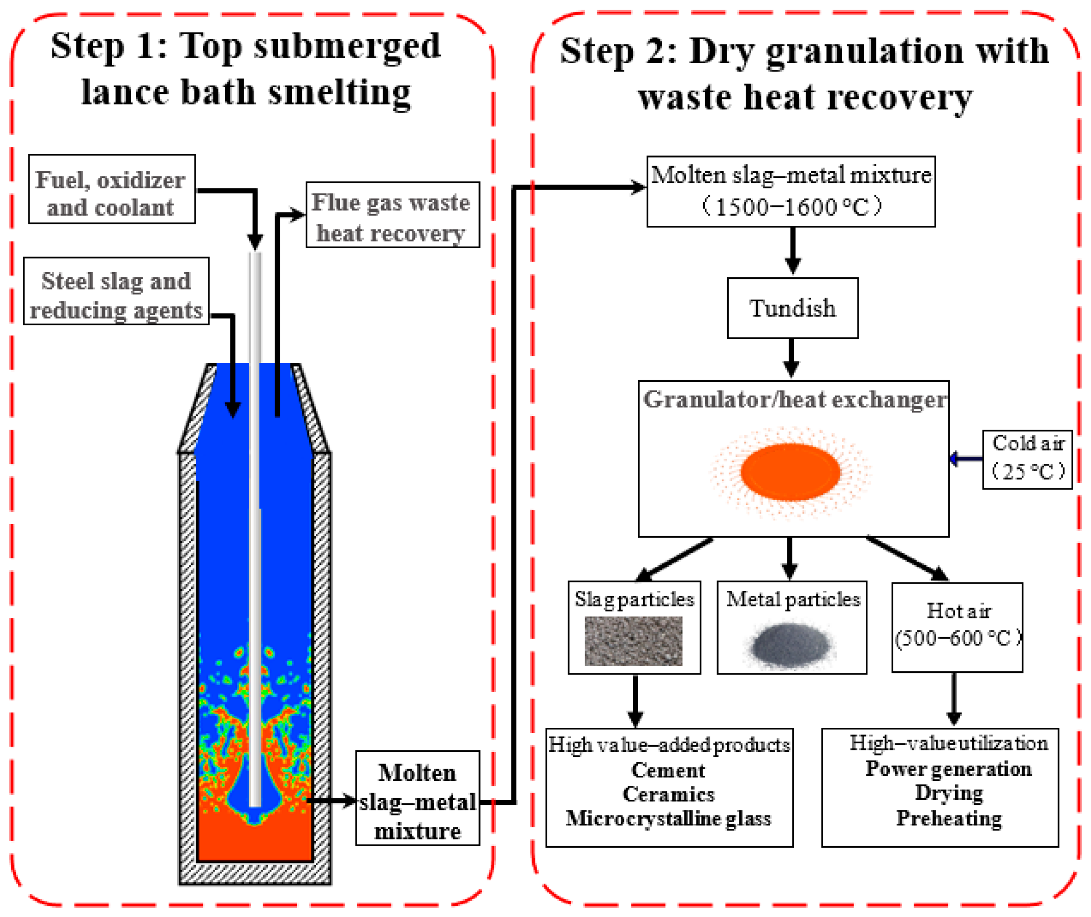
Figure 1 depicts a two-step steel slag treatment process developed by the present authors, which combines top submerged lance (TSL) bath smelting (first step) with dry and centrifugal granulation of molten slag–metal mixture with waste heat recovery (second step). In this process, solid or molten steel slag and a reducing agent are first charged into a TSL furnace, in which smelting reduction of the steel slag occurs, resulting in a molten slag–metal mixture. In the second step, the molten slag–metal mixture is fed into a centrifugal granulator that ultimately produces solid slag particles and solid metal particles, as well as hot air. While recovering valuable metal elements, the produced slag particles can be used for the production of high-value-added products such as cement, ceramics, microcrystalline glass, etc. Additionally, the obtained hot air can be used for, for instance, power generation and preheating or drying materials. Therefore, the technology illustrated in Figure 1 provides a fresh perspective and a new pathway for efficient and effective recycling and environmentally friendly treatment of steel slag and other metallurgical solid wastes, resulting in zero solid waste emissions.
Regarding the treatment of steel slag, the authors assume that the slag has already undergone the smelting reduction process, yielding a molten slag–metal mixture that contains metallic iron, and the slag composition is controlled to be close to that of blast furnace slag. In this regard, the primary emphasis of the present work is on the second-step process of centrifugal granulation of the molten slag–metal mixture, as depicted in the right-hand-side part of Figure 1. The present work aims to find a suitable cup design and operating parameters that can facilitate the production of enough fine slag and metal particles with uniform sizes.
2.1. Definition of Computational Domain
The flow process of a molten slag–metal mixture inside a spinning cup is schematically depicted in Figure 2, showing the formation of a liquid film and the flow direction of the liquid on a cross-section of the cup. The inner radius of the cup, denoted as R in Figure 2, is where slag is poured into the center of the cup at a consistent velocity. To efficiently utilize computational resources and take into account the characteristics of the rotational symmetry flow behavior of the molten slag–metal mixture on the inner face of the spinning cup, a periodic and axisymmetric two-dimensional CFD model is developed and used to simulate the flow and spread of slag on the inner face of the spinning cup. Figure 3 shows the internal structure of the spinning cup simulated in this study. The two-dimensional computation domain (the area enclosed by dashed lines on the right-hand side of the figure) and relevant boundary types (marked by arrows on the left-hand side of the figure) are defined in Figure 3. The width of the computation domain extends from the central axis of the spinning cup to the cup edge, whose inner radius is denoted by the symbol R, and the height extends a certain distance above the cup. The entire computation domain includes only half of the inner face of the cup and a limited portion of the region above the cup, in which slag and air co-exist. In this study, the inlet diameter of the slag is constant at 2 mm, the height of the cup sidewall is 5 mm, and the inclination angle of the cup sidewall is 90°. In addition, in order to investigate the influence of the cup size as a design parameter, the inner diameter of the spinning cup is set to 30, 35, 40, 45, and 50 mm, respectively.
2.2. Model Assumptions
The flow and spreading process of liquid on the inner face of the spinning cup is regarded as a typical free surface flow [15]. In the present study, this flow process involves a gas phase (air), a slag phase, and a metal phase that is dispersed in the slag phase, and there are significant free surfaces and interfaces among these phases. In order to carry out numerical simulations on such a complex multiphase flow phenomenon, the following basic assumptions are made:
- The mass flow rate of the molten slag–metal mixture at the inlet remains constant;
- Molten slag and metallic iron are well mixed at the inlet;
- The flow is isothermal, incompressible, and in a steady state;
- In the vicinity of the spinning cup, the airflow is influenced only by the spinning cup and the liquid motion;
- In order to limit the computation amount without losing accuracy, the computation domain is confined to covering appropriate portions of the pouring liquid stream and the air above the spinning cup;
- The center axis of the spinning cup precisely coincides with that of the cylindrical pouring stream of the molten slag–metal mixture.
2.3. Computation Grids, Boundary Conditions, and Material Properties
Figure 4 is a schematic representation of the grid division in the computational domain of the two-dimensional CFD model developed in this investigation. As seen, the computation grids (shown on the right-hand side of Figure 4) consist of non-uniform quadrilateral cells with sizes ranging from 0.1 mm to 0.3 mm. To ensure an accurate representation of the liquid film thickness, the grids are refined for the region where the molten slag–metal mixture spreads and forms a liquid film, and thus, the grid size is reduced to be below 0.1 mm (ranging from 0.03 mm to 0.1 mm). The computation grids are generated by using the Workbench utility of the ANSYS 15.0 software [29].
The boundary condition parameters (indicated in the left-hand side of Figure 4) for the two-dimensional CFD model are detailed in Table 1. Moreover, the physical properties of the flow medium adopted in this numerical simulation study are given in Table 2 [30,31]. In addition, interfacial tensions between air and liquid blast furnace slag, between air and liquid metallic iron, and between liquid blast furnace slag and liquid metallic iron are set to 0.5 N·m−1, 1.7 N·m−1, and 1.3 N·m−1, respectively [31].
2.4. Governing Equations
Based on the aforementioned basic assumptions, the flow behavior of the molten slag–metal mixture on and above the spinning cup can be characterized as a steady-state turbulent multiphase flow with free surfaces. Therefore, in this study, the method of volume of fluid (VOF) [33] and the SST k–ω turbulence model [34] are used to simulate the flow behavior of the multiphase liquid on the spinning cup inner face so as to track the phase interfaces. They can be described by the following system of partial differential equations:
- Continuity Equation:
- 2.
- Momentum Equation:
- 3.
- SST turbulence equations:
- 4.
- Volume fraction equation:
In Equations (1)–(4) ρ and μ are defined as:
where ρ is the density (kg·m−3); u is the velocity vector (m·s−1); p is the pressure (Pa); μ is the dynamic viscosity (Pa·s); μt is the turbulent viscosity (Pa·s); Fg is the source term due to gravity (N·m−3); Fs is the source term due to surface tension force (N·m−3), which is obtained by using the continuous surface force (CSF) method reported by Brackbill et al. [35]; k is the turbulence kinetic energy (m2·s−2); σk3 is the Prandtl number for turbulence kinetic energy; ω is the turbulence eddy frequency (s−1); σω2 is the Prandtl number for turbulence eddy frequency in the transformed k–ω turbulence model; σω3 is the Prandtl number for turbulence eddy frequency; Pk is the turbulent kinetic energy generation rate (W·m−3); Np is the total number of fluid phases; F1 is the mixing function; α3, β′ and β3 are the turbulence model constants; r is the volume fraction; and, subscripts α and β are the fluid phase identification indices.
2.5. Solution Method and Computation Scheme
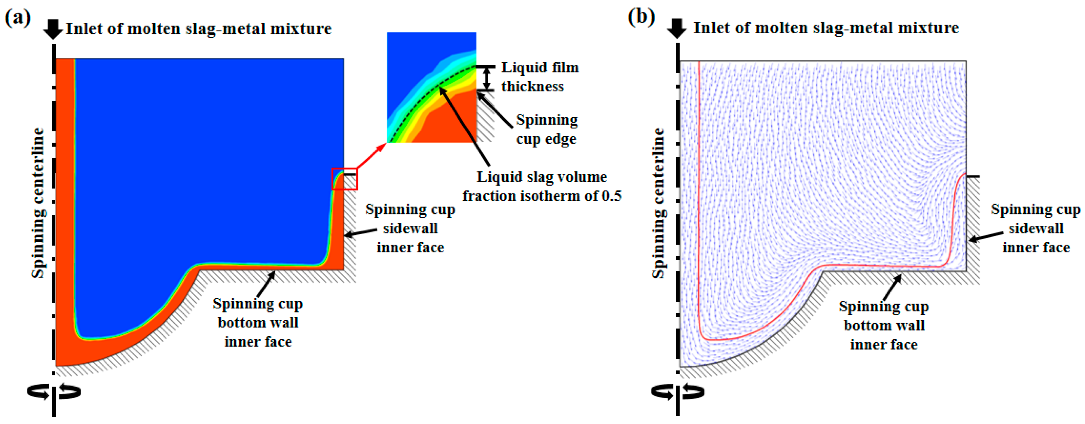
In order to simulate the molten slag–metal mixture and air multiphase flow field in the computation domain defined in Figure 3, the governing Equations (1)–(8) are numerically solved using the CFD simulation software package ANSYS CFX. Based on the distribution of the liquid film thickness on the inner face of the spinning cup in a radial direction, it can be predicted based on the phase interface distribution characterized by the liquid slag volume fraction isotherm at the value of 0.5. Then, through post-processing of the calculation results, the liquid slag film thickness at the edge of the spinning cup is obtained by measuring the vertical distance between the spinning cup edge and the 0.5 isotherm of the liquid slag volume fraction.
Table 3 gives the numerical computation scheme used in this study, by which the influences of operating parameters (liquid feeding rate, cup spinning speed, and metallic iron content in slag) and design parameters (spinning cup diameter) on the flow behavior and especially the liquid film thickness at the cup edge can be examined.
3. Results and Discussion
3.1. High-Temperature Experiments on Centrifugal Granulation of Molten Slag–Metal Mixtures
3.1.1. Experimental Condition
High-temperature experiments on centrifugal granulation of molten slag–metal mixtures using a spinning cup were carried out in this work on an experimental set-up schematically shown in Figure 5. A high-frequency induction furnace (not shown in Figure 5) was used to heat blast furnace slag mixed with different proportions of metallic iron powders to 1600–1750 °C, leaving it in a liquid state to form a molten slag–metal mixture. The melt mixture was then poured into a graphite crucible heated by another high-frequency induction furnace, which was used as a holding tundish. An opening hole at the bottom center of the tundish allowed the molten slag–metal mixture to flow into the spinning cup underneath, which broke the liquid into droplets. The droplets were then cooled to become solid particles by blowing in cold air. Directly below the tundish was the granulation chamber, in which a motor-driven spinning cup was installed to achieve centrifugal granulation of the molten slag–metal mixture. In addition, the sidewall of the granulation chamber was water-cooled to avoid the melt droplets adhering to the sidewall during their in-flight to hit the wall. The cooled and solidified slag and metal particles were finally collected in a particle collector bin below the granulation chamber.
The composition of the slag used for high-temperature experiments was similar to that of ironmaking slag, whose main composition reads: 43.45 wt.%CaO, 34.35 wt.%SiO2, 13.02 wt.%Al2O3, 5.83 wt.%MgO, and 0.15 wt.%MnO.
3.1.2. Experimental Results
Figure 6 shows the particle size distribution of slag particles in terms of mass fraction and accumulative mass fraction obtained from the high-temperature centrifugal granulation experiments. It can be seen from this figure that when the liquid feeding rate is 0.5 kg·min−1, and the cup spinning speed is 2500 RPM, the measured diameter of the slag particles mainly falls in the range between 0.27 mm and 2.8 mm, and nearly 98% of slag particles have a diameter smaller than 0.88 mm. These slag particles are fine enough for efficient heat exchange with air and also possess enough high glass content (>90%) for use in making cement. Also, from the relationship between the Sauter mean diameter (SMD) of the experimentally granulated slag particles and the metallic iron content in the slag, as can be seen from the figure, the SMD decreases gradually with the increase in the metallic iron content. For the liquid feeding rate of 0.5 kg·min−1 and the cup spinning speed of 2500 RPM, when the metal iron content increases from 5% to 15%, the SMD of the slag particles decreases by 13.77%, indicating that the participation of the metal in the slag promoted the breakup of the slag to a certain extent.
3.2. Spreading Flow Behavior of Molten Slag–Metal Mixture Inside a Spinning Cup
3.2.1. Behavior of Molten Slag Flow on Spinning Cup Inner Face
Figure 7 illustrates the numerical simulation results of the CFD model for the spreading flow behavior of liquid slag on the inner face of the spinning cup. Figure 7a depicts the slag volume fraction contour plot, in which the red color area represents the slag region, and the blue color area stands for the air region; the border between the red and blue areas indicates where the molten slag-free surface is located. Figure 7b shows the velocity vector plot, in which the curve referring to the slag volume fraction isotherm is equal to 0.5, which represents the profile of the free surface. Therefore, in this study, the liquid film thickness is defined as the vertical distance from the edge of the spinning cup to this curve, i.e., the surface corresponding to a slag phase volume fraction of 0.5, as shown in the local enlargement in Figure 7a. From the simulation results, it can be seen that, under the influence of gravity, the slag enters the spinning cup along the centerline of the spinning cup at a specific speed until it reaches the bottom of the spinning cup. Under the combined effect of frictional resistance and centrifugal force, the flow speed of slag is gradually close to the spinning speed of the spinning cup and spreads on the inner face of the spinning cup to form a liquid film. The thickness of the liquid film in the direction of the radius of the spinning cup gradually becomes thinner, and until the slag reaches the sidewall of the spinning cup, the slag begins to climb up along the sidewall. In this process, due to the influence of gravity and the friction of the sidewall, the slag will slightly accumulate, resulting in the thickening of the liquid film on the wall face. At the same time, under the action of centrifugal force, the liquid film gradually thins out in the vertical direction on the inner face of the sidewall, and under the action of inertial force, the liquid film flies away from the spinning cup after reaching its upper mouth edge. From the velocity field of the slag and air, it can be seen that the larger velocities are mainly concentrated in the melt injection region, the inside of the liquid film, and the neighboring air region.
3.2.2. Behavior of Liquid Metal Flow on Spinning Cup Inner Face
The outcomes of the CFD model numerical simulation shown in Figure 8 demonstrate the flow characteristics of liquid metallic iron motion in molten slag on the spinning cup’s inner face. Figure 8a depicts the slag and metal volume fraction contours, where the metal phase is marked by the black color, the slag phase is denoted by the red color, and the air phase is represented by the blue color. Figure 8b illustrates the model-predicted velocity vector field, in which the liquid metal fraction contours are included as well. It can be seen from Figure 8a that the liquid metal, together with the slag, enters the spinning cup along the centerline of the cup at a specific velocity under the effect of gravity. Since the metal and the slag are immiscible with each other in a molten state, they form a kind of layered or wrapped pattern driven by their interfacial tension. After the liquid metal reaches the bottom center of the spinning cup, some liquid metal accumulates there due to the influence of gravity and friction on the inner wall of the cup. Under the combined effect of frictional resistance and centrifugal force, the flow velocity of the metal gradually approaches the spinning speed of the cup. In the horizontal direction along the radius of the spinning cup, the slag spreads to form a nearly stable layer of film, in which liquid metal accumulates due to the immiscible feature of the two substances. Under the effect of interfacial tension, the metal is unevenly dispersed inside the liquid slag film layer. Until the metal reaches the sidewall of the spinning cup, it starts, along with the liquid slag, to climb up the cup wall under the effect of centrifugal force. At this time, due to the influence of gravity and density, the metal flows relatively slower than the slag, resulting in its accumulation around the bottom corner of the spinning cup. Finally, under the action of inertial force, after reaching the edge of the upper mouth of the spinning cup, both the slag and the metal flew away from the cup.
3.3. Effect of Design and Operating Parameters on Liquid Film Thickness at the Edge of Spinning Cup
3.3.1. Effect of Spinning Cup Size on Liquid Film Thickness
Figure 9 illustrates a cross-sectional view of the volume fraction and velocity vector fields in different-sized spinning cups (with different radius R) predicted by the CFD model, using the same color legends for identifying the phases as those used in Figure 7 and Figure 8. Also, in this figure, the free surface profiles are indicated by dashed lines in the velocity vector field on the left-hand side. The borders between red and blue color regions on the right-hand side, from which the liquid film thickness is determined by measuring the vertical distance between the cup edge and the borderline, and the liquid film thickness values are labeled in the local enlargements of different spinning cups in the figure. Figure 10 illustrates the variation in the model-predicted liquid film thickness with the change in the diameter of the spinning cup. This figure shows a nearly linear relationship between the cup diameter and the liquid film thickness, but they are inversely proportional. For instance, the liquid film thickness decreased by 19.26% (from 0.135 mm to 0.109 mm) when the spinning cup diameter increased from 30 mm to 50 mm. As the diameter of the spinning cup increases, its internal surface area also increases, which means that the area covered by the liquid film formed by the slag on the spinning cup also increases. In addition, the linear velocity at the edge of the spinning cup is proportional to the radius of the cup, and as the diameter of the spinning cup increases, so does the linear velocity at the edge of the cup. Since the flow of slag is usually constant, as the flow is distributed over a larger surface area, the amount of slag per unit area decreases, resulting in a thinner liquid film thickness. When the liquid breaks up in ligament disintegration mode, driven by centrifugal force, a thinner liquid film forms thinner liquid ligaments, which eventually break up into finer droplets and consequently produce smaller particles. Owing to having significantly large specific surface areas for heat transfer, the slag particles with small sizes will possess sufficiently high vitreous content after rapid cooling, which is conducive to the later utilization of the slag.
3.3.2. Effect of Cup Spinning Speed on Liquid Film Thickness
Figure 11 shows the relationship between the CFD model’s predicted liquid film thickness at the spinning cup’s edge and the spinning speed of the cup. The figure demonstrates, as expected, a negative correlation between the two parameters. For instance, for a spinning cup with a diameter of 30 mm, when the cup spinning speed is increased from 2000 RPM to 3000 RPM, the liquid film thickness decreases from 0.147 mm to 0.131 mm, a reduction of about 10.88%. As the cup’s spinning speed increases, the centrifugal force on the slag also increases, which causes the slag to spread rapidly over the surface of the spinning cup to form a thin liquid film. At the same time, the higher the cup’s spinning speed, the faster the radial velocity of the slag on the surface of the spinning cup, resulting in a thin film of liquid before it leaves the spinning cup, which facilitates the granulation into droplets with smaller diameters. Nevertheless, an increase in cup spinning speed will lead to an increase in the power consumption of the motor driving system. If the liquid film thickness is too thin, the resultant liquid ligaments may be too small in diameter and are unable to break up into droplets in a timely manner, leading to a larger probability of forming slag wool instead of particles upon cooling. Therefore, it is necessary to control the spinning cup speed in an appropriate range in the centrifugal granulation process.
3.3.3. Effect of Liquid Feeding Rate on Liquid Film Thickness
According to the CFD model simulation results, Figure 12 shows the relationship between the liquid film thickness at the spinning cup’s edge and the liquid feeding rate. This figure indicates that as the liquid feeding rate increases, the liquid film thickness increases nearly linearly. For instance, for every 1 kg·min−1 increase in the slag feeding rate, the liquid film thickness increases by about 28.15%. As the liquid feeding rate increases, more volume of slag passes over the surface of the spinning cup per unit of time. Since the spinning cup speed and diameter of the cup remain constant, the effect of centrifugal force is relatively constant, so more slag will form a thicker liquid film on the inner surface of the spinning cup.
3.3.4. Effect of Metal Content in Slag on Liquid Film Thickness and Slag Particle Size
As shown in Figure 13, assuming that the liquid feeding rate and the cup spinning speed remain constant, a variation in the metallic iron content in slag almost has no influence on the liquid film thickness at the spinning cup’s edge. Changes in the metal content of slag mainly affect the physical properties of the slag. However, these changes in physical properties have little effect on the formation and thickness of the liquid film during centrifugal granulation in a spinning cup. Meanwhile, the liquid film thickness is mainly determined by the centrifugal force and the liquid feeding rate, which are kept constant under this condition. Nevertheless, since the liquid film thickness at the cup edge affects the slag particle size, the effect of liquid film thickness on the granulation effect of the molten slag–metal mixture needs to be further investigated. A quantitative relationship between the liquid film thickness at the edge of the spinning cup predicted by the CFD model and the arithmetic mean diameter of the slag particles measured by high-temperature centrifugal experiments is established based on experimental and simulation results, as given in Table 4. The data in this table indicate that, as the liquid film thickness increases, so does the diameter of the slag particles. The average ratio between the mean slag particle diameter and the liquid film thickness decreases with an increase in metallic iron content in the slag. For instance, in the metallic iron content range of 5–15%, this ratio is around 4.25 (±0.3), which is close to the value of 4.0 reported on centrifugal granulation of pure molten blast furnace slag [21]. In addition, the data in Table 4 further indicate that, as the metallic iron content in slag increases, the ratio between the mean slag particle diameter and the liquid film thickness decreases nearly linearly. As a result, if the desired granulation effect is required, this relationship may be utilized to forecast appropriate liquid film thickness and establish the relevant control parameters (e.g., liquid feeding rate, spinning cup size, and cup spinning speed) for achieving such liquid film thickness.
3.4. Model Validation
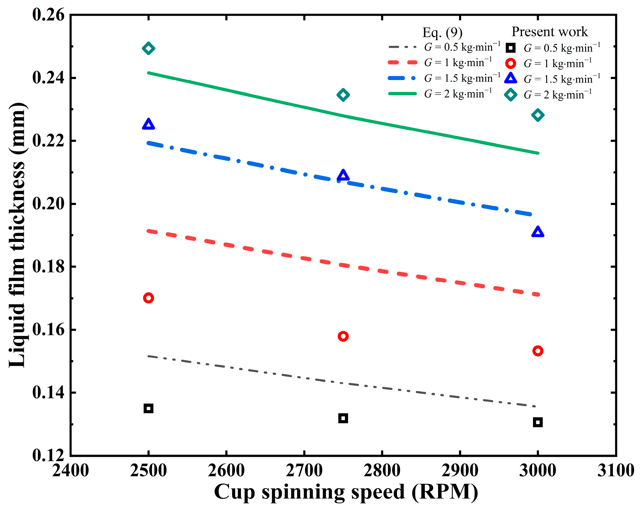
The two-dimensional CFD model developed in this work for simulating the flow and spreading behavior of molten slag–metal mixture in a spinning cup was built based on the two-dimensional CFD model previously established and experimentally verified for simulating a single slag phase (blast furnace slag) [16]. Therefore, the present CFD model would basically replicate the validity of the previous single-slag phase CFD model. Furthermore, as mentioned in the preceding section, the average ratio (4.25) between the arithmetic mean diameter of slag particles and the liquid film thickness for centrifugal granulation of molten slag–metal mixture is close to the value of 4.0 reported in the literature for the single slag phase [21]. In addition, the authors also conducted a comparison between the simulation outcomes of this research and a theoretical model (Equation (9)) reported in the literature regarding the flow of a liquid film over a spinning disc [19], which reads
where h is the liquid film thickness at the edge of the spinning cup (mm); G is the liquid feeding rate (kg·min−1); μ is the liquid dynamic viscosity (Pa·s); R is the radius of the disc or inner radius of the spinning cup (mm); Ω is the spinning speed (RPM); and ρ is the liquid density (kg·m−3).
The comparison results are illustrated in Figure 14. As seen from this figure, the simulation results obtained in the present work well approach, both in value and in trend, those calculated using Equation (9). A little larger discrepancy at a low liquid feeding rate (<1 kg·min−1) is likely caused by the shape difference between the cup and the disc. For the same diameter and under the same operating conditions, a spinning cup has a larger wetting area of the liquid film and thus produces a thinner film than a disc of the same diameter does, and this tendency becomes more obvious for low liquid feeding rates.
4. Conclusions
The present study developed and used a two-dimensional steady-state CFD numerical model to simulate the flow and spreading behavior of a molten slag–metal mixture containing metallic iron (e.g., molten steel slag) during centrifugal granulation with a spinning cup. The thickness of the liquid film at the spinning cup’s edge, which directly affects the particle size after granulation, was predicted for different design and operating parameters. To validate the results of the numerical simulations, high-temperature experiments on centrifugal granulation of a molten slag–metal mixture using a spinning cup were also performed as part of this study. Using the method in the paper can be expected to solve the problem of bulk solid waste treatment, such as steel slag, which is of great significance in promoting the resource utilization of solid waste, protecting the environment, and promoting sustainable development. The following conclusions can be drawn from the present work:
- The molten slag–metal mixture exhibits an immiscible state between the slag and the liquid metal on the inner face of the spinning cup, forming layering or wrapping patterns. Due to the action of interfacial tension, the metallic iron is unevenly dispersed inside the liquid slag film layer.
- The results of the high-temperature centrifugal granulation experiments indicate that an increase in cup spinning speed increases the proportion of smaller-sized slag particles. For a constant liquid feeding rate and cup spinning speed, an increase in metallic iron content in slag increases the Sauter mean diameter of the slag particles. For the cup spinning speed of 2500 RPM, when the metallic iron content in slag increases from 5% to 15%, the Sauter mean diameter of the slag particles decreases by 13.77%.
- The liquid film thickness at the spinning cup edge increases with the increase in liquid feeding rate but decreases with the increase in cup spinning speed. For the spinning cup with a diameter of 30 mm, the liquid film thickness decreases by 10.88% when the cup spinning speed is increased from 2000 RPM to 3000 RPM. For every 1 kg·min−1 increase in the liquid feeding rate, the liquid film thickness increases by about 28.15%. When the spinning cup diameter is increased from 30 mm to 50 mm, the liquid film thickness can be reduced by 19.26%.
- The diameter of slag particles correlates positively with the increase in the liquid film thickness at the spinning cup edge. The ratio between the arithmetic mean diameter of slag particles and the liquid film thickness decreases nearly linearly with the increase in the metallic iron content in slag, and, on average, the mean diameter of the slag particles is approximately 4.25 times the liquid film thickness at the spinning cup edge. Therefore, this ratio can be utilized for estimating the slag particle size based on the liquid film thickness at the spinning cup edge predicted using the two-dimensional CFD model developed in this work.
Author Contributions
Conceptualization, J.W., M.Z. and Y.P.; methodology, J.W., M.Z. and Y.P.; validation, S.L. and Y.H.; formal analysis, J.W., M.Z. and Y.P.; investigation, J.W. and M.Z.; resources, M.Z. and Y.P.; data curation, J.W., M.Z. and Y.H.; writing—original draft preparation, J.W., M.Z. and Y.P.; writing—review and editing, J.W., Y.P. and P.M.; visualization, J.W. and S.L.; supervision, Y.P. and M.Z.; project administration, M.Z. and Y.H.; funding acquisition, Y.P. and P.M. All authors have read and agreed to the published version of the manuscript.
Funding
This research received no external funding.
Data Availability Statement
Data supporting reported results can be found in this paper.
Conflicts of Interest
The authors declared that they have no conflicts of interest in this work.
References
- Guo, J.; Bao, Y.; Wang, M. Steel slag in China: Treatment, recycling, and management. Waste Manag. 2018, 78, 318–330. [Google Scholar] [CrossRef] [PubMed]
- Gao, W.; Zhou, W.; Lyu, X.; Liu, X.; Su, H.; Li, M.; Wang, H. Comprehensive utilization of steel slag: A review. Powder Technol. 2023, 422, 118449. [Google Scholar] [CrossRef]
- Wu, J.; Tan, Y.; Li, P.; Wang, H.; Zhu, X.; Liao, Q. Centrifugal-Granulation-Assisted thermal energy recovery towards low-carbon blast furnace slag treatment: State of the art and future challenges. Appl. Energy 2022, 325, 119835. [Google Scholar] [CrossRef]
- Rauscher, J.; Kelly, R.; Cole, J. An Asymptotic Solution for the Laminar Flow of a Thin Film on a Rotating Disk. J. Appl. Mech. 1973, 40, 43–47. [Google Scholar] [CrossRef]
- Liu, J.; Yu, Q.; Guo, Q. Experimental investigation of liquid disintegration by rotary cups. Chem. Eng. Sci. 2012, 73, 44–50. [Google Scholar] [CrossRef]
- Liu, J.; Yu, Q.; Li, P.; Du, W. Cold experiments on ligament formation for blast furnace slag granulation. Appl. Therm. Eng. 2012, 40, 351–357. [Google Scholar] [CrossRef]
- Mizuochi, T.; Akiyama, T.; Shimada, T.; Kasai, E. Feasibility of Rotary Cup Atomizer for Slag Granulation. Trans. Iron Steel Inst. Jpn. 2001, 41, 1423–1428. [Google Scholar] [CrossRef]
- Sisoev, G.; Matar, O.; Lawrence, C. Axisymmetric wave regimes in viscous liquid film flow over a spinning disk. J. Fluid Mech. 2003, 495, 385–411. [Google Scholar] [CrossRef]
- Tan, Y.; Wang, H.; Zhu, X.; Lv, Y.; Ding, Y.; Liao, Q. Film fragmentation mode: The most suitable way for centrifugal granulation of large flow rate molten blast slag towards high-efficiency waste heat recovery for industrialization. Appl. Energy 2020, 276, 115454. [Google Scholar] [CrossRef]
- Burns, J.; Ramshaw, C.; Jachuck, R. Measurement of liquid film thickness and the determination of spin-up radius on a rotating disc using an electrical resistance technique. Chem. Eng. Sci. 2003, 58, 2245–2253. [Google Scholar] [CrossRef]
- Ghiasy, D.; Boodhoo, K.; Tham, M. Thermographic analysis of thin liquid films on a rotating disc: Approach and challenges. Appl. Therm. Eng. 2012, 44, 39–49. [Google Scholar] [CrossRef]
- Lv, Y.; Zhu, X.; Wang, H.; Dai, M.; Ding, Y.; Wu, J.; Liao, Q. A hybrid cooling system to enable adhesion-free heat recovery from centrifugal granulated slag particles. Appl. Energy 2021, 303, 117645. [Google Scholar] [CrossRef]
- Purwanto, H.; Mizuochi, T.; Akiyama, T. Prediction of Granulated Slag Properties Produced from Spinning Disk Atomizer by Mathematical Model. Mater. Trans. 2005, 46, 1324–1330. [Google Scholar] [CrossRef]
- Purwanto, H.; Mizuochi, T.; Tobo, H.; Takagi, M.; Akiyamaet, T. Characteristics of Glass Beads from Molten Slag Produced by Rotary Cup Atomizer. Mater. Trans. 2004, 45, 3286–3290. [Google Scholar] [CrossRef]
- Pan, Y.; Witt, P.; Xie, D. CFD simulation of free surface flow and heat transfer of liquid slag on a spinning disc for a novel dry slag granulation process. Prog. Comput. Fluid Dyn. 2010, 10, 292–299. [Google Scholar] [CrossRef]
- Chang, Q.; Li, X.; Ni, H.; Zhu, W.; Pan, C.; Hu, S. Modeling on Dry Centrifugal Granulation Process of Molten Blast Furnace Slag. ISIJ Int. 2015, 55, 1361–1366. [Google Scholar] [CrossRef]
- Li, M.; Zhao, J.; Zhang, X.; Xun, N.; Meng, H.; Wu, Z.; Wang, S. Effects of Granulator Structure and Cooperating Mode with Slag Tube on the Centrifugal Granulation Characteristics of Molten Slag. Appl. Therm. Eng. 2021, 193, 117026. [Google Scholar] [CrossRef]
- Wang, D.; Ling, X.; Peng, H. Theoretical analysis of free-surface film flow on the rotary granulating disk in waste heat recovery process of molten slag. Appl. Therm. Eng. 2013, 63, 387–395. [Google Scholar] [CrossRef]
- Pan, Y.; Witt, P.; Kuan, B.; Xie, D. CFD Modelling of the Effects of Operating Parameters on the Spreading of Liquids on a Spinning Disc. J. Comput. Multiph. Flows 2014, 6, 49–64. [Google Scholar] [CrossRef]
- Pan, Y.; Zhao, M.; Ma, P.; Li, J.; Huo, Z.; Li, H. CFD Modeling of Melt Spreading Behavior on Spinning Discs and Cups for Centrifugal Granulation of Molten Slag. J. Sustain. Metall. 2019, 5, 195–203. [Google Scholar] [CrossRef]
- Liu, J.; Yu, Q.; Dou, C. Experimental study on rotating cup granulation of blast furnace slag. J. Northeast. Univ. (Nat. Sci.) 2009, 30, 1163–1165. (In Chinese) [Google Scholar]
- Zhang, S.; Zhao, M.; Ma, P.; Pan, Y.; Meng, F. Numerical modeling of centrifugal granulation of molten blast furnace slag using spinning cups. Iron Steel 2020, 55, 127–133. [Google Scholar]
- Gao, J.; Feng, Y.; Zhang, W.; Feng, D.; Zhang, X. Prediction on particle size characteristics of high-temperature liquid blast furnace slag in a centrifugal granulation process. Powder Technol. 2020, 376, 527–536. [Google Scholar] [CrossRef]
- Gao, J.; Feng, Y.; Feng, D.; Zhang, X. Granulation performance by hybrid centrifugal air blast technique for treatment of liquid slag. Powder Technol. 2021, 392, 204–211. [Google Scholar] [CrossRef]
- Tan, Y.; Ding, B.; Shi, J.; Yan, H.; Wu, Y.; Wu, J. Modelling the film fragmentation of industrial-scale centrifugal granulation of high-temperature molten slag. Powder Technol. 2023, 426, 118654. [Google Scholar] [CrossRef]
- Peng, L.; Li, L.; Zhao, W. Numerical study of inlet eccentricity on liquid film spreading and splitting in centrifugal granulation assisted thermal energy recovery. Powder Technol. 2022, 414, 118079. [Google Scholar] [CrossRef]
- Liu, Z.; Tu, Q.; Ma, W.; Liu, J.; Tao, S. Experimental investigation on centrifugal granulation of molten yellow phosphorus slag. Chem. Eng. Res. Des. 2023, 197, 548–557. [Google Scholar] [CrossRef]
- Xu, N.; Zhao, J.; Zhang, X.; Li, M.; Ma, C.; Wu, Z.; Meng, H.; Wang, S. Flow Characteristics of the Liquid Film During Centrifugal Granulation of Liquid Slag on the Surface of Rotary Cup. J. Sustain. Metall. 2022, 8, 632–645. [Google Scholar] [CrossRef]
- ANSYS Inc. ANSYS CFX User’s Manual, Release 15.0; ANSYS Inc.: Canonsburg, PA, USA, 2013. [Google Scholar]
- Inaba, S.; Kimura, Y.; Shibata, H.; Ohta, H. Measurement of physical properties of slag formed around the raceway in the working blast furnace. ISIJ Int. 2004, 44, 2120–2126. [Google Scholar] [CrossRef]
- Chen, J. Steelmaking Commonly Used Charts Data Book, 1st ed.; Metallurgical Industry Press: Beijing, China, 1984; p. 231. [Google Scholar]
- Ramirez-Argaez, M.; Conejo, A.; Guzman, Y.; Trapaga, G. Influence of the top slag layer on the flow dynamics in AC electric arc furnaces. Int. J. Eng. Syst. Model. Simul. 2010, 2, 217–225. [Google Scholar]
- Hirt, C.; Nichols, B. Volume of fluid (VOF) method for the dynamics of free boundaries. J. Comput. Phys. 1981, 39, 201–225. [Google Scholar] [CrossRef]
- Menter, F. Two-equation eddy-viscosity turbulence models for engineering applications. AIAA J. 1994, 32, 1598–1605. [Google Scholar] [CrossRef]
- Brackbill, J.; Kothe, D.; Zemach, C. A continuum method for modeling surface tension. J. Comput. Phys. 1992, 100, 335–354. [Google Scholar] [CrossRef]
Figure 1.
Process flow diagram of a two-step process of steel slag treatment through a combination of top-submerged lance bath smelting reduction with dry and centrifugal granulation of molten slag–metal mixture with waste heat recovery. (Red and blue colours stand for molten slag–metal mixture and gaseous phase, respectively).

Figure 2.
Schematic illustration of the cross-section shows the flow process of liquid in a spinning cup.
Figure 2.
Schematic illustration of the cross-section shows the flow process of liquid in a spinning cup.
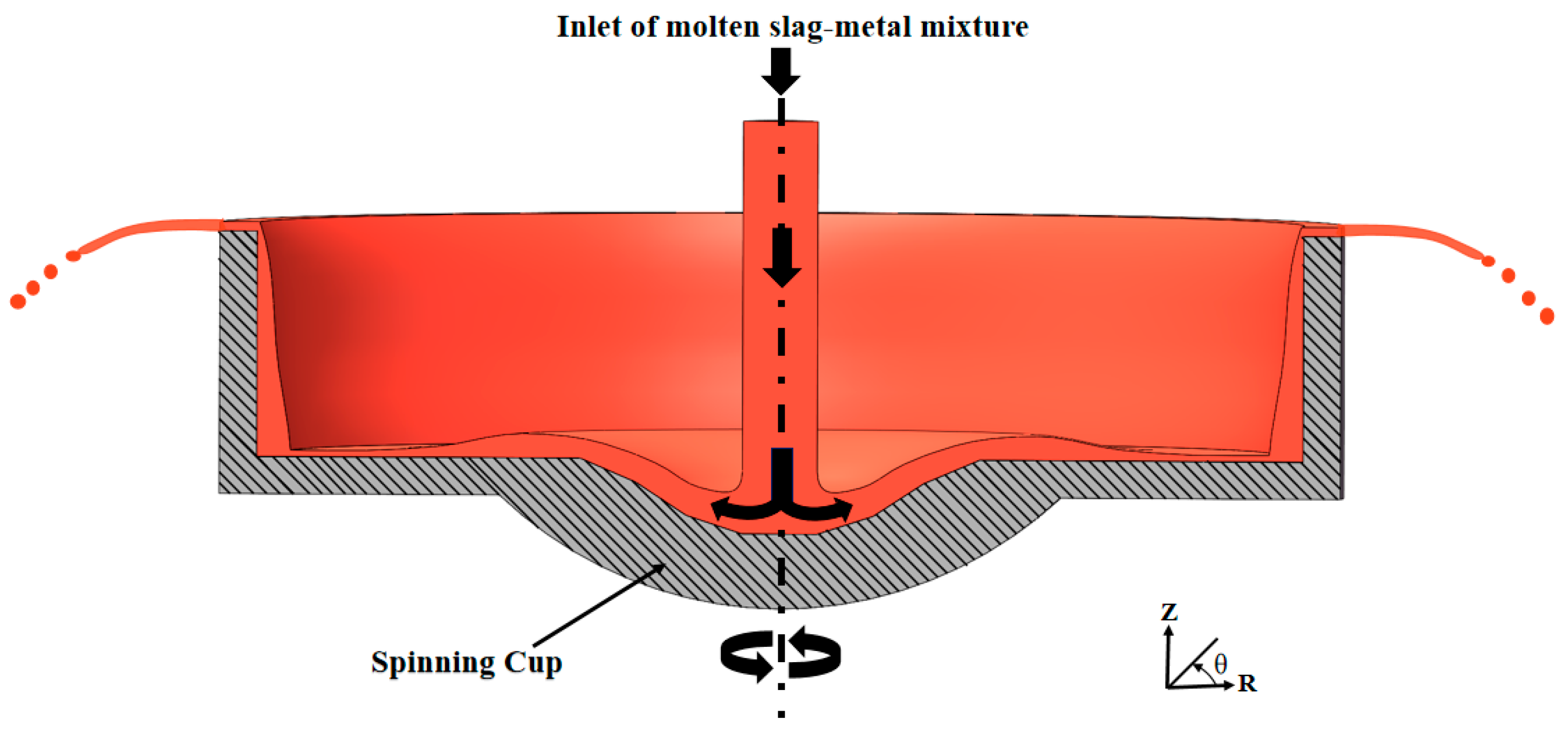
Figure 3.
Schematic illustration of the computational domain defined in the two-dimensional CFD model.
Figure 3.
Schematic illustration of the computational domain defined in the two-dimensional CFD model.
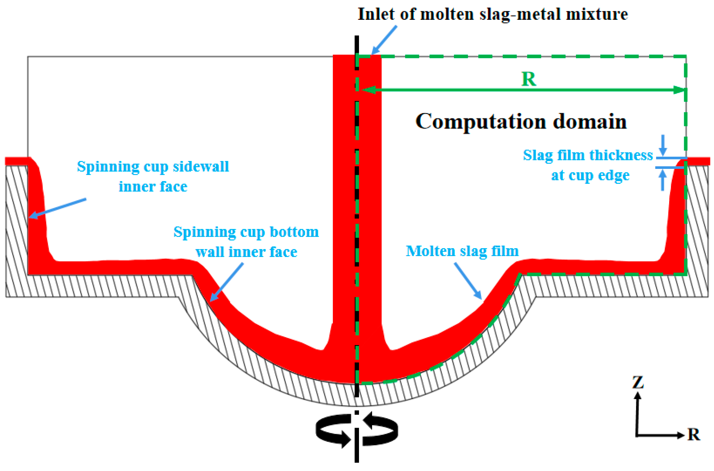
Figure 4.
Schematic diagram of computation grid division of the computational domain (right-hand side) and relevant boundary condition types (left-hand side) for the two-dimensional CFD model (the letters A to G represent the junction points of various boundaries of the two-dimensional computation domain, c.f., Table 1).
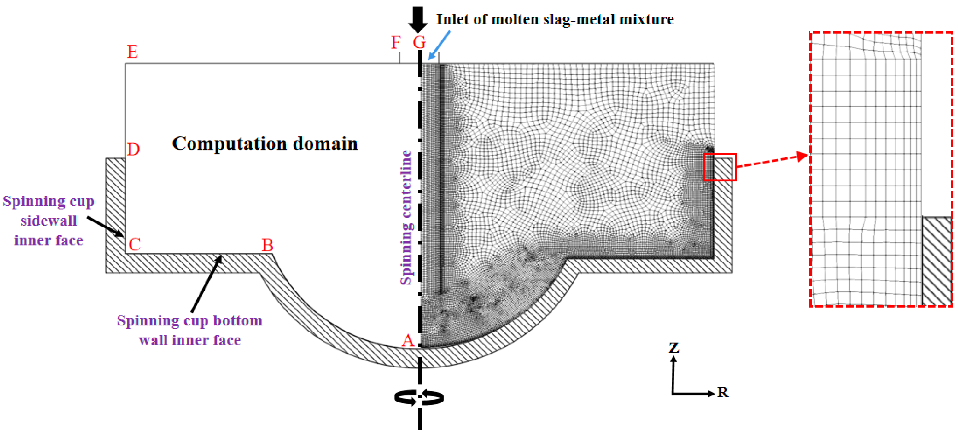
Figure 5.
Schematic diagram of high-temperature experimental set-up for centrifugal granulation of molten slag–metal mixture using a spinning cup.
Figure 5.
Schematic diagram of high-temperature experimental set-up for centrifugal granulation of molten slag–metal mixture using a spinning cup.

Figure 6.
Slag particle size distribution in terms of mass fraction and accumulative mass fraction measured from high-temperature experiments on centrifugal granulation of molten slag–metal mixtures using a spinning cup.
Figure 6.
Slag particle size distribution in terms of mass fraction and accumulative mass fraction measured from high-temperature experiments on centrifugal granulation of molten slag–metal mixtures using a spinning cup.

Figure 7.
Behavior of molten slag flow on the inner face of the spinning cup simulated by the two-dimensional CFD model: (a) volume fraction contour plot, (b) velocity vector field (liquid feeding rate = 0.5 kg·min−1, cup spinning speed = 2500 RPM, cup sidewall height = 5 mm, and metallic iron content in slag = 10%).

Figure 8.
Plot of slag and metal volume fraction contours showing flow behavior of metal on the inner surface of spinning cup simulated by CFD model: (a) volume fraction contour plot, (b) velocity vector field (liquid feeding rate = 0.5 kg·min−1, cup spinning speed = 3000 RPM, cup sidewall height = 5 mm, and metallic iron content in slag = 10%).
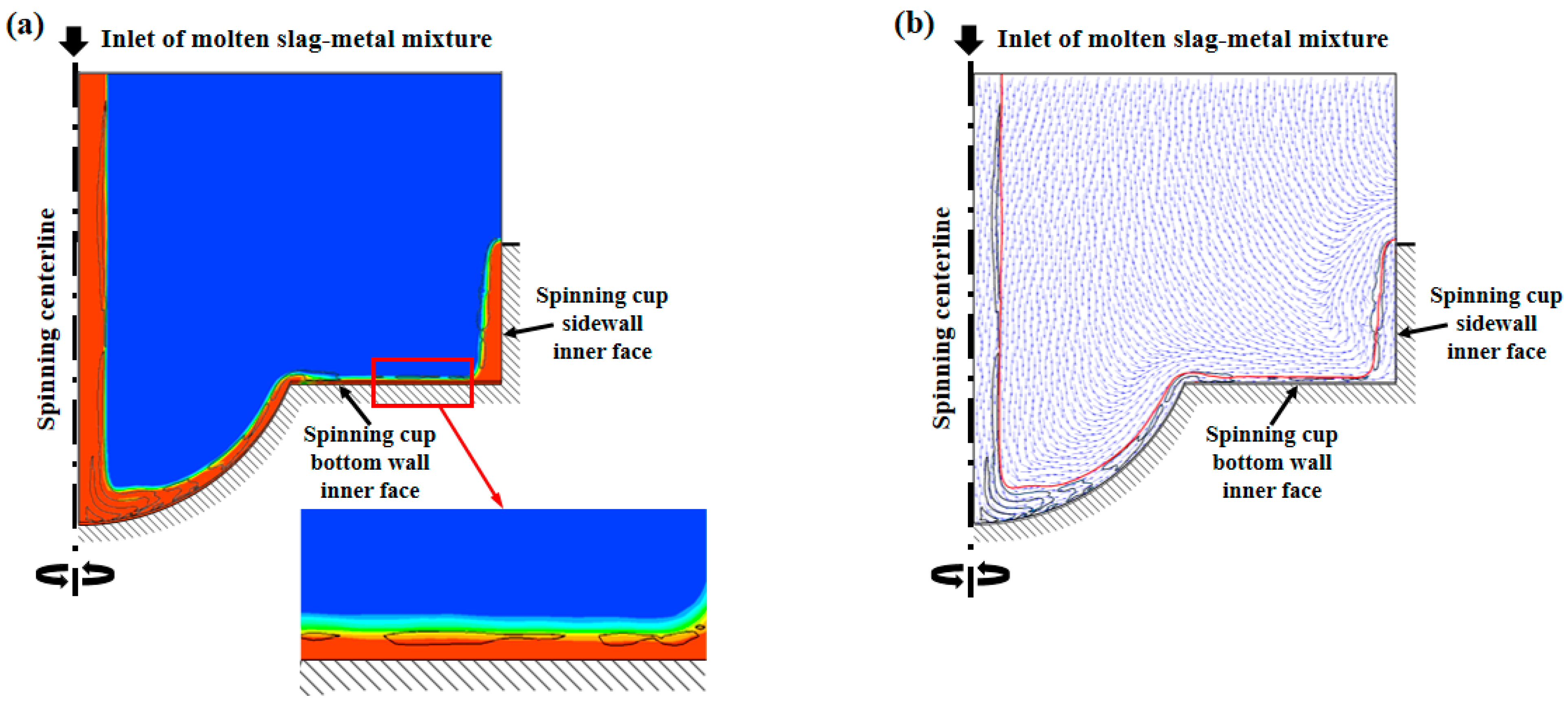
Figure 9.
CFD model predicted velocity vector fields (left) and phase volume fraction contours (right) of molten slag–metal mixture flow inside the spinning cup with different radius (R): (a) R = 15 mm, (b) R = 17.5 mm, (c) R = 20 mm, (d) R = 22.5 mm, (e) R = 25 mm (liquid feeding rate = 0.5 kg·min−1, cup spinning speed = 2500 RPM, cup sidewall height = 5 mm, and metallic iron content in slag = 10%).
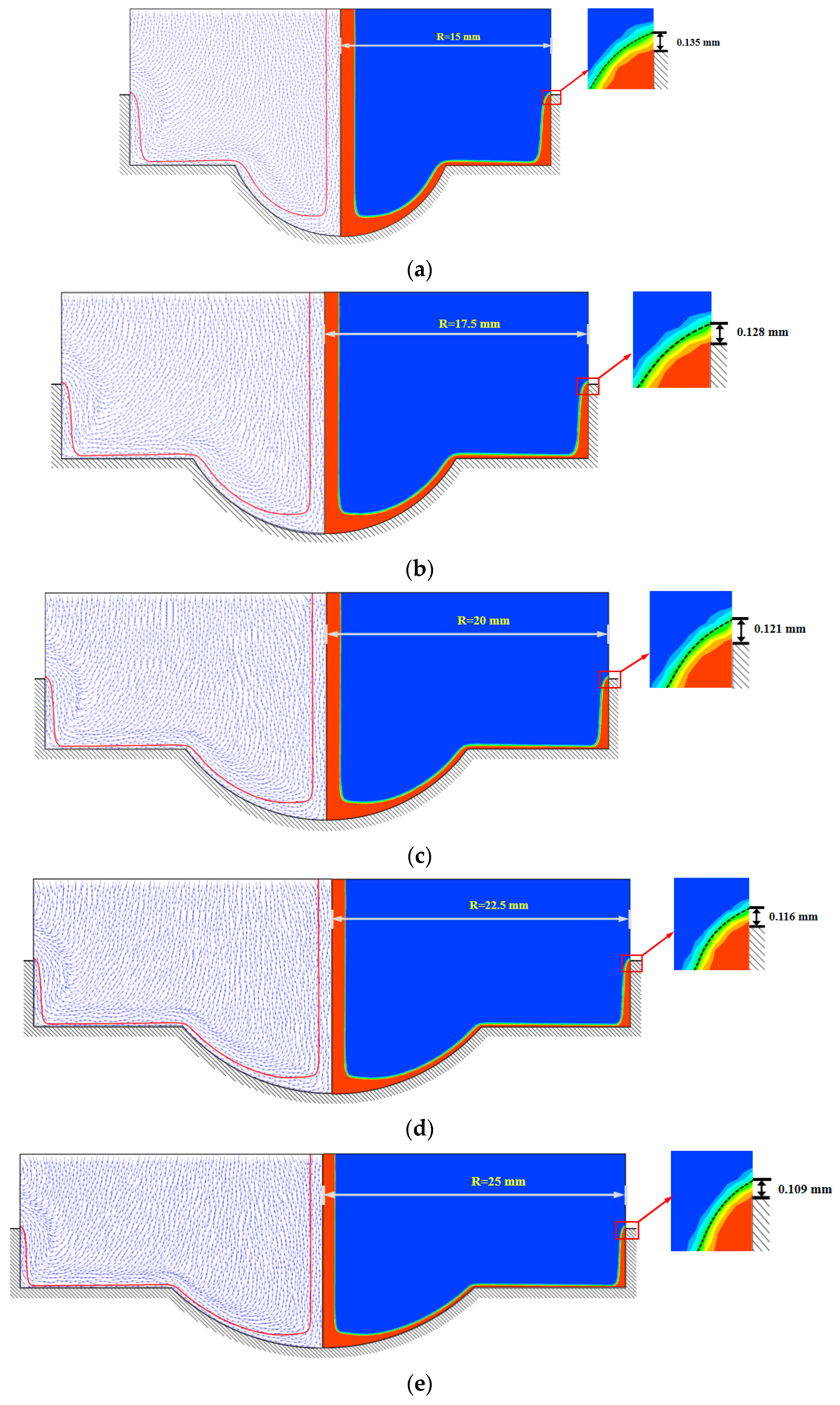
Figure 10.
Effect of spinning cup diameter on liquid film thickness (slag feeding rate = 0.5 kg·min−1, cup spinning speed = 2500 RPM, cup sidewall height = 5 mm, metallic iron content in slag = 10%).
Figure 10.
Effect of spinning cup diameter on liquid film thickness (slag feeding rate = 0.5 kg·min−1, cup spinning speed = 2500 RPM, cup sidewall height = 5 mm, metallic iron content in slag = 10%).
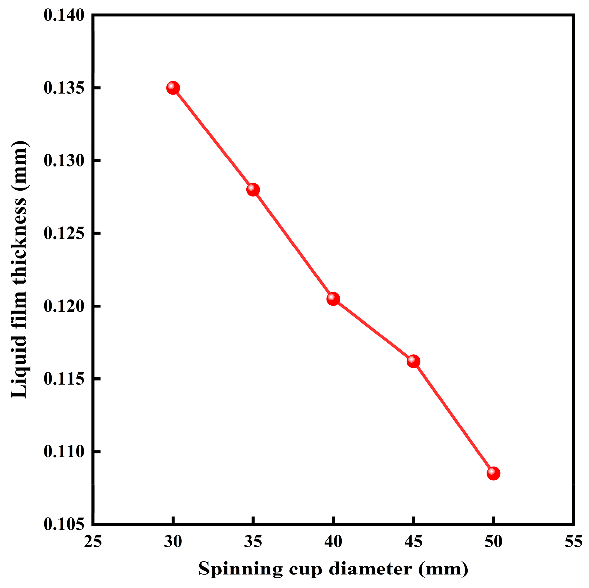
Figure 11.
Effect of cup spinning speed on liquid film thickness (liquid feeding rate = 0.5 kg·min−1, cup sidewall height = 5 mm, metallic iron content in slag = 10%).
Figure 11.
Effect of cup spinning speed on liquid film thickness (liquid feeding rate = 0.5 kg·min−1, cup sidewall height = 5 mm, metallic iron content in slag = 10%).
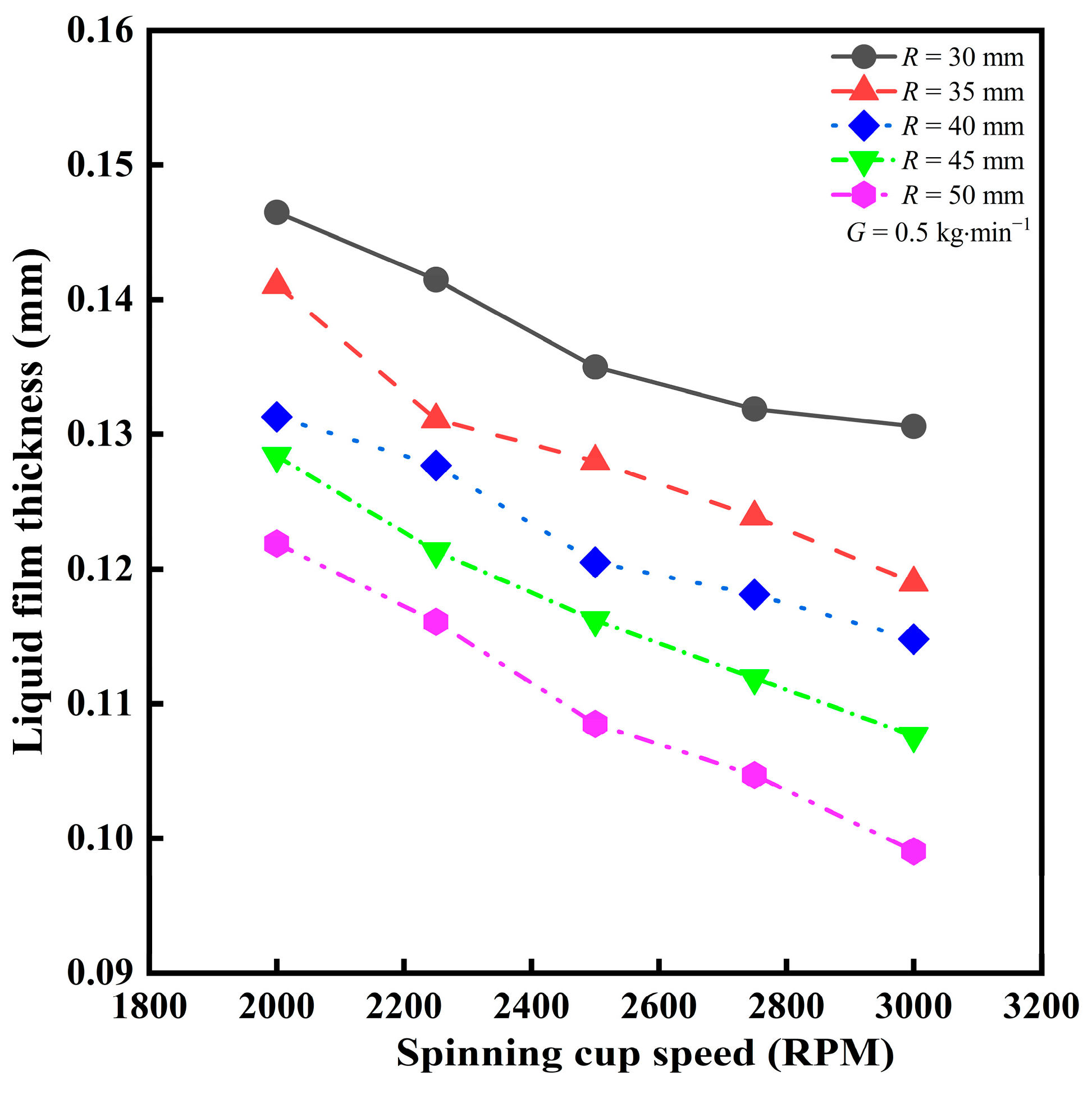
Figure 12.
Effect of liquid feeding rate on liquid film thickness (cup spinning speed = 2500 RPM, cup sidewall height = 5 mm, metallic iron content in slag = 10%).
Figure 12.
Effect of liquid feeding rate on liquid film thickness (cup spinning speed = 2500 RPM, cup sidewall height = 5 mm, metallic iron content in slag = 10%).
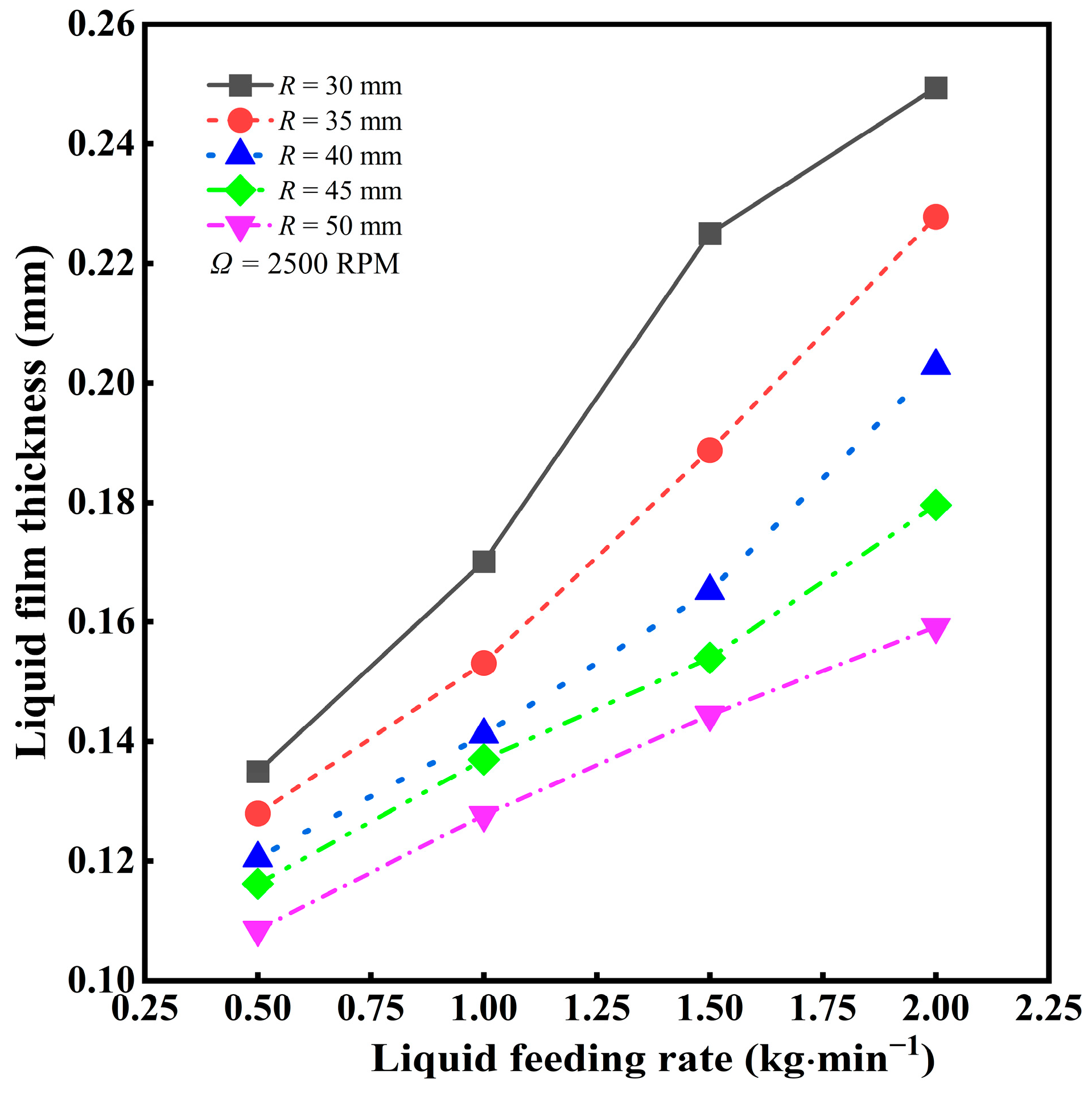
Figure 13.
Effect of metallic iron content in slag on liquid film thickness.
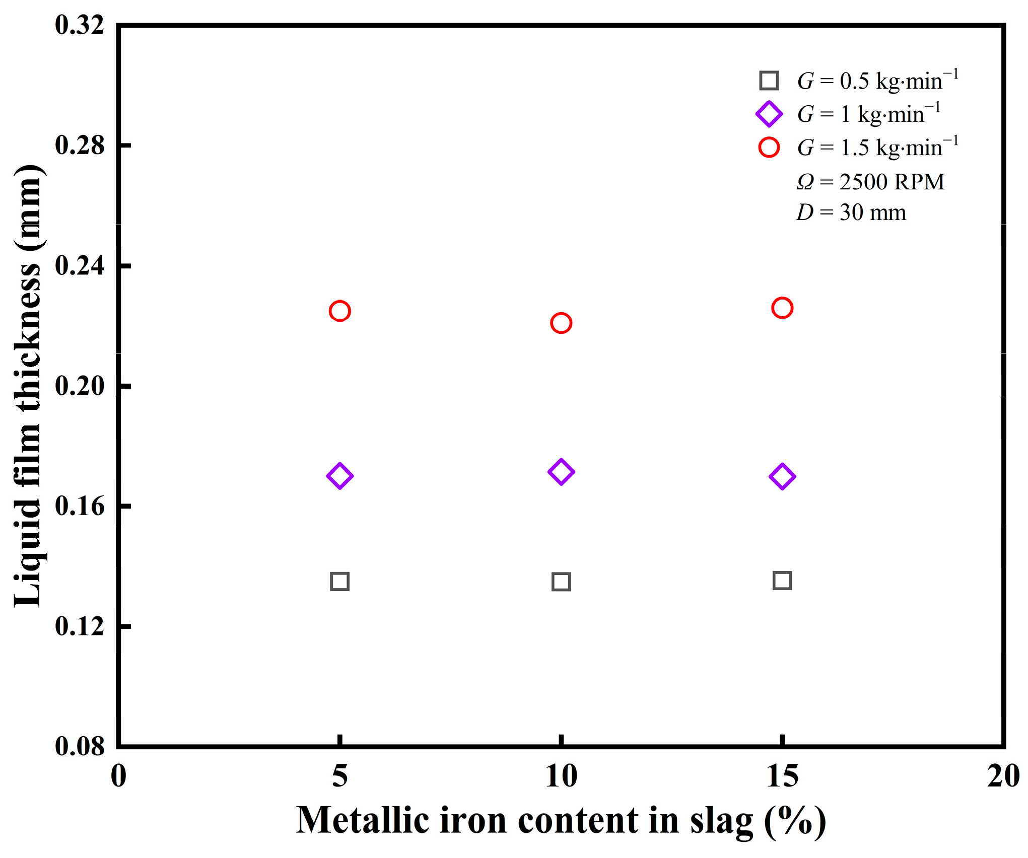
Figure 14.
Comparison of the liquid film thickness predicted in this work with that calculated using Equation (9) (spinning cup diameter = 30 mm, cup sidewall height = 5 mm, metallic iron content in slag = 10%).
Figure 14.
Comparison of the liquid film thickness predicted in this work with that calculated using Equation (9) (spinning cup diameter = 30 mm, cup sidewall height = 5 mm, metallic iron content in slag = 10%).

Table 1.
Boundary conditions for a two-dimensional CFD model.
| Boundary | Boundary Name | Boundary Type | Condition |
|---|---|---|---|
| ABC | Spinning cup bottom wall inner face | Wall | Non-slip spinning wall |
| CD | Spinning cup sidewall inner face | Wall | Non-slip spinning wall |
| DE | Side boundary | Opening | Fixed pressure (=0 Pa) |
| EF | Top boundary | Opening | Fixed pressure (=0 Pa) |
| FG | Liquid inlet | Inlet | Fixed mass flowrate |
| AG | Center axis | Rotational symmetrical axis | Zero flux |
| Material | Density (kg·m−3) | Viscosity (Pa·s) |
|---|---|---|
| Liquid blast furnace slag | 2590 | 0.5 |
| Air | 1.185 | 1.831 × 10⁻⁵ |
| Steel | 7200 | 0.0065 |
Table 3.
Numerical computation scheme for two-dimensional CFD model simulations.
| Simulation Case Number | Liquid Feeding Rate (kg·min−1) | Cup Spinning Speed (RPM) | Spinning Cup Diameter (mm) | Metallic Iron Content in Slag (%) |
|---|---|---|---|---|
| 1 | 0.5 | 2000 | 30 | 10 |
| 2 | 0.5 | 2250 | 30 | 10 |
| 3 | 0.5 | 2500 | 30 | 10 |
| 4 | 0.5 | 2750 | 30 | 10 |
| 5 | 0.5 | 3000 | 30 | 10 |
| 6 | 1 | 2500 | 30 | 10 |
| 7 | 1 | 2750 | 30 | 10 |
| 8 | 1 | 3000 | 30 | 10 |
| 9 | 1.5 | 2500 | 30 | 10 |
| 10 | 1.5 | 2750 | 30 | 10 |
| 11 | 1.5 | 3000 | 30 | 10 |
| 12 | 2 | 2500 | 30 | 10 |
| 13 | 2 | 2750 | 30 | 10 |
| 14 | 2 | 3000 | 30 | 10 |
| 15 | 0.5 | 2500 | 35 | 10 |
| 16 | 0.5 | 2500 | 40 | 10 |
| 17 | 0.5 | 2500 | 45 | 10 |
| 18 | 0.5 | 2500 | 50 | 10 |
| 19 | 0.5 | 2500 | 30 | 5 |
| 20 | 1 | 2500 | 30 | 5 |
| 21 | 1.5 | 2500 | 30 | 5 |
| 22 | 0.5 | 2500 | 30 | 15 |
| 23 | 1 | 2500 | 30 | 15 |
| 24 | 1.5 | 2500 | 30 | 15 |
Table 4.
Ratios between experimental slag particle mean diameter and CFD model predicted liquid film thickness for different metallic iron content in slag (liquid feeding rate = 0.5 kg·min−1, cup spinning speed = 2500 RPM, spinning cup diameter = 30 mm).
Table 4.
Ratios between experimental slag particle mean diameter and CFD model predicted liquid film thickness for different metallic iron content in slag (liquid feeding rate = 0.5 kg·min−1, cup spinning speed = 2500 RPM, spinning cup diameter = 30 mm).
| Metallic Iron Content in Slag (%) | Slag Particle Diameter to Liquid Film Thickness Ratio |
|---|---|
| 5 | 4.57 |
| 10 | 4.24 |
| 15 | 3.94 |
| Average | 4.25 |
Disclaimer/Publisher’s Note: The statements, opinions and data contained in all publications are solely those of the individual author(s) and contributor(s) and not of MDPI and/or the editor(s). MDPI and/or the editor(s) disclaim responsibility for any injury to people or property resulting from any ideas, methods, instructions or products referred to in the content. |
© 2024 by the authors. Licensee MDPI, Basel, Switzerland. This article is an open access article distributed under the terms and conditions of the Creative Commons Attribution (CC BY) license (https://creativecommons.org/licenses/by/4.0/).
Share and Cite
MDPI and ACS Style
Wang, J.; Pan, Y.; Zhao, M.; Ma, P.; Lv, S.; Huang, Y. Computational Fluid Dynamics Numerical Simulation on Flow Behavior of Molten Slag–Metal Mixture over a Spinning Cup. Processes 2024, 12, 372. https://doi.org/10.3390/pr12020372
AMA Style
Wang J, Pan Y, Zhao M, Ma P, Lv S, Huang Y. Computational Fluid Dynamics Numerical Simulation on Flow Behavior of Molten Slag–Metal Mixture over a Spinning Cup. Processes. 2024; 12(2):372. https://doi.org/10.3390/pr12020372
Chicago/Turabian StyleWang, Jun, Yuhua Pan, Ming Zhao, Ping Ma, Shali Lv, and Yawei Huang. 2024. "Computational Fluid Dynamics Numerical Simulation on Flow Behavior of Molten Slag–Metal Mixture over a Spinning Cup" Processes 12, no. 2: 372. https://doi.org/10.3390/pr12020372
Note that from the first issue of 2016, this journal uses article numbers instead of page numbers. See further details here.