

Optimization of Exergy Efficiency in a Walking Beam Reheating Furnace Based on Numerical Simulation and Entropy Generation Analysis

School of Energy and Environmental Engineering, University of Science and Technology Beijing, Beijing 100083, China
*
Author to whom correspondence should be addressed.
Processes 2024, 12(3), 451; https://doi.org/10.3390/pr12030451
Submission received: 8 February 2024
/
Revised: 19 February 2024
/
Accepted: 20 February 2024
/
Published: 23 February 2024
(This article belongs to the Special Issue Thermal Analysis, Modeling and Simulation in Engineering Processes)
Abstract
:An analysis of entropy generation and exergy efficiency can effectively explore the energy-saving potential of reheating furnaces. This paper simulated the combustion, flow, and heat transfer in a walking beam reheating furnace by establishing a half-furnace model. The entropy generation rate distribution of different thermal processes was numerically calculated. The effect of slab residence time and fuel distribution in the furnace was studied to optimize exergy efficiency. The results indicated that combustion and radiative heat transfer are the primary sources of entropy generation. Irreversible losses accounted for 26.39% of the total input exergy, in which the combustion process accounted for 16.43%, and radiative heat transfer accounted for 8.47%. Reducing the residence time by 60 min decreased irreversible exergy loss by about 2.5% but increased heat dissipation and exhaust exergy loss by 5.8%. Energy saving can only be achieved when the heat exchanger’s exergy recovery efficiency exceeds 36% under different fuel supplies. Keeping the total fuel supply unchanged, increasing the fuel mass flow rate in heating-I zone while decreasing it in heating-II zone resulted in a 1.5% decrease in exergy efficiency. This study provides new insights into the energy-saving potential of reheating furnaces.
1. Introduction
A reheating furnace is essential equipment in a hot rolling production line, mainly used to raise steel temperature to about 1200 °C to reduce deformation resistance, and accounts for about 15–20% of the total energy consumption in steel production. Improving the energy efficiency of reheating furnaces can significantly reduce operating costs.
There has been a lot of research into reheating furnaces. Numerical simulation methods have been widely used to simulate the heating process of a slab in a reheating furnace. G. Tang et al. [1] numerically analyzed the slab heating process in a walking beam reheating furnace using the dynamic mesh method and validated it by industrial experiments. B. Mayr et al. [2] simplified a slab as a highly viscous fluid and simulated the slab heating process. Y. Liu et al. [3] investigated the performance of fuel–air combustion in a reheating furnace at different flow rates and inlet conditions, and the steel temperature data were moved through a UDF. M. Gu et al. [4] analyzed the temperature uniformity of a billet based on a heating unit model by varying the fuel flow rate with time.
In an energy efficiency analysis of heating furnaces, slab residence time and fuel distribution are important parameters for optimizing the heating process. They are often combined with energy equilibrium and exergy equilibrium to evaluate the energy efficiency of heating furnaces. S.H. Han et al. [5] performed a 3D unsteady numerical simulation and energy balance analysis of a reheating furnace to obtain the optimal slab residence time. D. Chen et al. [6] analyzed the distribution of region thermal efficiency based on an energy apportionment model of a reheating furnace. H. Feng [7] analyzed the energy and exergy equilibriums of reheating furnaces and evaluated their energy efficiency under different energy balance test cases. J. Zhao et al. [8] investigated process matching and waste heat recovery measures by establishing an energy and exergy flow model for the hot rolling process. W. Rong et al. [9] investigated the influence of slab oxidation on exergy efficiency.
However, energy and macro exergy equilibrium methods do not accurately assess the rationality of energy use. In a furnace, the smaller the energy level difference between the high-temperature flue gas and the low-temperature slab, the higher the quality of energy utilization. The larger the temperature difference in heat transfer, the higher the thermal efficiency, which causes a contradiction between energy utilization efficiency and utilization quality. If the fuel allocation is unreasonable, it will lead to the unreasonable distribution of energy levels in different furnace zones, such as heat transfer from flue gas of high energy level to a slab of low energy level. If the residence time is short, the difference in the heat transfer energy level between flue gas and a slab will be significant, and the energy utilization quality will be severe, but energy efficiency will be better. The opposite is true for long residence time. Therefore, optimizing the energy efficiency of reheating furnaces must consider exergy analysis and be deeply integrated with heating process parameters. In terms of the causes of energy loss, the lower the entropy generation in the hearth, the lower the irreversible energy losses and the higher the energy efficiency. However, in addition to the furnace hearth, the exergy recovery efficiency of exhaust gases in the flue must also be considered. The variation in the heating process will cause changes in the flue gas discharge temperature. The energy level of high-temperature flue gas is high. A reasonable selection of heat exchangers with high exergy recovery efficiency will effectively improve the energy utilization of the whole furnace.
With the development of numerical models for entropy generation and exergy balance, the direct and accurate calculation of exergy losses for different heating processes in a thermal system has become an effective method for assessing the rationality of energy use. The entropy generation analysis (EGA) method was first proposed by A. Bejan [10] and is an important means of exploring the energy-saving potential of thermal processes by identifying the cause of energy loss. In engineering, N. Lior et al. [11] used the EGA method to analyze the exergy loss of a low NOx pulverized coal combustion furnace. C. Lou and Z. Zhang [12] conducted a decoupled analysis of radiative heat transfer in a coal-fired boiler based on its entropy generation characteristics. K. Pitchandi et al. [13] and A. Arefian et al. [14] performed parameter optimization studies of collectors and heat exchangers using the EGA method, respectively. In our previous study, we analyzed the influence of billet charging temperature and fuel mass flow rate on the entropy generation and exergy efficiency of a regenerative reheating furnace based on a heating unit model [15]. However, there have been no reports on numerical analyses of the entropy generation and exergy equilibrium of a walking beam reheating furnace or analyses of the effects of residence time and fuel allocation on energy efficiency.
In order to optimize energy use in reheating furnaces from the viewpoint of entropy generation and exergy equilibrium, a half-furnace model is defined in Section 2.1 to simulate the heat and mass transfer processes in a walking beam reheating furnace. Section 2.2 and Section 2.3 define the local entropy generation rate calculation model and the exergy equilibrium model of the furnace based on the local entropy generation rate, respectively. Section 3 calculates the entropy generation rate distribution from the furnace flow and temperature field simulation results using the UDF postprocessing method. In Section 4, the exergy loss of each thermal process in the furnace hearth is accurately calculated based on the entropy generation result, and the energy balance of the furnace is obtained. The effects of process parameters such as slab residence time, fuel distribution, and heat exchangers’ exergy recovery efficiency on furnace efficiency are discussed.
2. Models and Parameters
2.1. Numerical Models
The structure of the walking beam reheating furnace is shown in Figure 1a, and half of the furnace is selected for modeling. The furnace is 50 m long and 10.2 m wide and is divided into the preheating zone (9 m), heating-I zone (26 m), heating-II zone (26 m), and soaking zone (15 m). There are 10 straight burners in the upper and lower hearths of the heating zone, respectively. The soaking zone has 12 flat flame burners in the upper hearth and 4 straight burners in the lower hearth. The preheating zone has no burners. The preheating and heating zones have 8 water-cooled beams. In the soaking zone, the beams are misaligned, and a fixed beam is added at the centerline of the furnace, making a total of 9 water-cooled beams. The mesh results are shown in Figure 1b, in which polyhedral mesh is used for fluid field and water-cooled beams, and hexahedral mesh is used for the slab.
Figure 1c shows the contact heat conduction model between beams and the slab. A water-cooled beam consists of two water pipes welded together. The height of the skid button is 20 mm, and the height of the welding pad is 80 mm. The contact material between the slab and the skid button is air, and the thickness is 0.00001 m. Coupled heat transfer boundaries are specified between the outer surface of beams, slabs, and high-temperature flue gas. The heat transfer coefficient of the inner wall of the water pipes is 1248 W/(m2·K). The center cross-section along the furnace length is symmetrical. The furnace lining is a mixed heat transfer boundary condition. The wall thickness is 0.486 m, with a thermal conductivity of 2 W/(m·K). The air nozzles and gas nozzles of the burner are mass flow inlet boundaries with concentric circle structures. The typical fuel mass flow rates of the heating-I zone, heating-II zone, and soaking zone are 0.8, 1.0, and 0.3 kg/s, respectively. There is no swirl flow in the straight flame burners. The air swirl angle of the flat flame burners is 45 °C. The fuel is a mixed gas, in which the volume fractions of H2, O2, CO, CO2, H2O, CH4, and N2 are 29.57%, 0.02%, 17.18%, 10.31%, 3.01%, 14.03%, and 25.88%, respectively. The flue gas outlet is located at the side wall of the slab entry in the furnace and is set as the pressure outlet boundary condition.
Commercial software ANSYS SpaceClaim(2021R1) and ANSYS Fluent (2021R1) were used for model design, mesh, and calculations of the velocity and temperature fields in the furnace. The standard k-epsilon (2-eqn) model is used for the turbulence model, the eddy dissipation model with diffusivity source term is selected for the turbulence–chemical reaction interaction, and the discrete ordinates (T4) model is selected for the radiative heat transfer. The steel temperature data are transferred every 300 s from one slab to the next through a UDF to realize the entry and exit of the slab from the furnace. If the slab temperature data are stable, this indicates that the transient model has reached convergence.
2.2. Formulations of Entropy Generation
The entropy generation in the high-temperature furnace is related to conductive, convective, radiative heat transfer, viscous dissipation, mass diffusion, and combustion. In this work, the irreversible entropy generations caused by the radiative heat exchange in the medium and on solid surfaces are both considered and calculated based on the temperature and fluid simulation results using the UDF postprocessing method. The total entropy generation in the reheating furnace is expressed as follows:
where, is entropy generation, W K−1. is the local entropy generation rate, W m−3 K−1 (in medium) or W m−2 K−1 (on solid surface). ‘cc’, ‘ch’, ‘md’, ‘vis’, and ‘rad’ are the abbreviations for conductive and convective heat transfer, chemical reactions, mass diffusion, viscous dissipation, and radiative heat transfer, respectively. ‘F’, ‘W’, and ‘S’ are the abbreviations for fluid, wall surface, and slab surface, respectively. ‘A’ is the area of the solid surface grid. ‘V’ is the volume of the fluid cell.
For unit volume fluid, the local entropy generation rate resulting from the irreversibility of the conductive and convective heat transfer process is expressed as [16],
The local entropy generation rate caused by the irreversibility of the viscous dissipation process is expressed as [17],
Ignoring the tiny Solet and Duval effects, the local entropy generation rate caused by the irreversibility of the mass diffusion process is expressed as [17]:
The local entropy generation rate due to chemical reactions is expressed as [18]:
In Formulas (2)–(5), stands for different species, is effective thermal conductivity, W m−1 K−1 h, is the velocity vector, m s−1. is the viscous stress tensor, N m−2. is density, kg m−3. is the gas constant of species i, J kg−1 K−1. is the diffusivity of species i, m2 s−1. is the mass fraction of species i. is the molar fraction of species i. is the rate of reaction i, kmol m−3 s−1. H is the enthalpy, J kg−1. is the mean molecular weight, kg kmol−1. is the mass flow rate, kg s−1.
The local radiative entropy generation rate due to the absorption, emission, and scatteration in the medium is defined as [16]:
where
The local radiative entropy generation rate at the wall and billet surfaces due to the absorption and emission is expressed as (taking the wall surfaces as an example) [16]:
where
In Formulas (6)–(9), h is the Planck constant, 6.6261 × 10⁻³⁴ J s. is the speed of light in vacuum, m s−1. is the Boltzmann constant, J K−1. is the wavelength, m. is the exergy loss due to irreversibility, W. is the spectral radiative intensity, W m−3 sr−1. is the spectral radiative intensity of blackbody, W m−3 sr−1. is the spectral radiation temperature, K. is the spectral absorption coefficient, m−1. is the spectral scattering coefficient, m−1. is the solid angle, sr. is the unit position vector, is the unit direction vector, is the unit outward normal vector of a boundary wall.
2.3. Formulations of Exergy Equilibrium
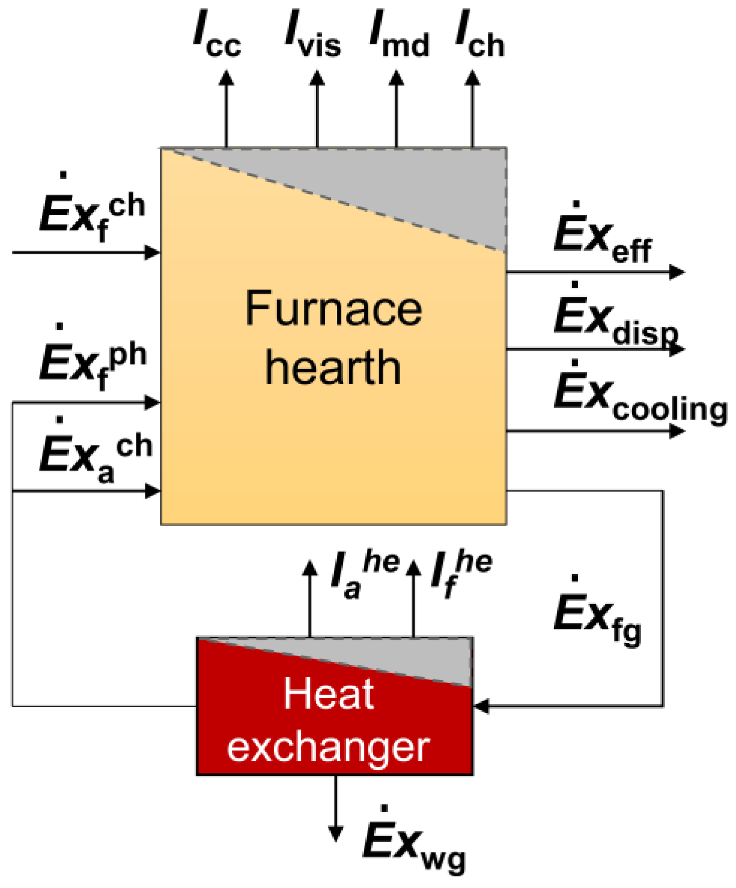
Figure 2 shows the exergy equilibrium model of the furnace hearth and the whole furnace (containing the heat exchanger in the flue).
2.3.1. Exergy Equilibrium of the Furnace Hearth
After ignoring the oxidation heat of the slabs, the exergy equilibrium model of the furnace hearth can be written as:
is the sum of exergy losses caused by the irreversible processes,
where is the chemical exergy of fuel, W. is the physical exergy of fuel, W. is physical exergy of air, W. is the effective exergy carried by slabs, W. is the physical exergy carried away by flue gas. is the exergy loss caused by heat dissipation of the wall, is the abbreviation for irreversible exergy loss of different thermal processes, W. is the environment temperature, 25 °C.
2.3.2. Exergy Equilibrium of the Whole Furnace System
The exergy equilibrium of the whole furnace system can be written as:
where and are the irreversible exergy loss of the heat exchange process from flue gas to fuel and air in regenerators and can be expressed as:
The exergy taken away by the waste gas can be expressed as:
where is the temperature of flue gas before heat exchange, is the temperature of exhaust flue gas after heat exchange, and are the preheated temperature of air and gas, respectively. and are the mass flow rates of air and gas, respectively.
2.3.3. Exergy Efficiency
The exergy efficiency and exergy destruction rate of the furnace hearth are defined as:
The exergy efficiency of the whole furnace system is defined as,
3. Numerical Simulation Results
3.1. Convergent and Validation of Slab Temperature
The variation in the average temperature distribution of the slab in the furnace is shown in Figure 3a. The horizontal axis is the number of slabs in the furnace. When the temperature distribution of the slabs along the furnace length is stable, the model is considered convergent. It takes about 19 h from the slab charging at room temperature until the whole furnace state reaches stability, consistent with the actual heating process. In order to verify the accuracy of the numerical simulation results, an industrial experiment was carried out to track and measure the billet temperature. Figure 3b compares the simulated and measured temperature data. The rising trend of the two data sets is basically the same and accurately reflects the temperature change of the slab heating process.
3.2. Distribution of Temperature and Fluid Fields
Figure 4a,b illustrate the temperature distributions of the medium in the furnace and furnace wall, respectively. The maximum temperature of the medium is approximately 1900 °C. The maximum temperature of the furnace wall is about 1300 °C. The flat flame burner creates a circular flame that spreads on the top of the furnace in the soaking zone and equalizes the temperature of the slab. The conventional burner in the heating zone forms a long, steady flame and plays a major role in heating the slab. The furnace wall temperature shows a significant step change along the furnace length due to the change in fuel mass flow rates in each zone. The temperature distribution of typical sections is shown in Figure 4c. Both flue gas and slab temperatures are lower near the flame, as demonstrated by the section of x = 21 m, because the flame is not fully spread out and is blocked by the water-cooled beams. Figure 4d shows that the flue gases are collected in the preheating zone, leading to a strong convective heat transfer effect with slabs. The flue gas temperature leaving the furnace is approximately 780 °C.
3.3. Distribution of Entropy Generation Rate
The entropy generation distributions of conductive and convective heat transfer, viscous dissipation, mass diffusion, combustion, and radiative heat transfer at typical cross-sections are shown in Figure 5a–e, respectively. The entropy generation of conductive and convective heat transfer is mainly distributed in the place with a large temperature gradient along the two sides of the flame, with a maximum of about 9550 W m3 K−1. The entropy generation of mass diffusion mainly occurs in the place with a large concentration gradient near the burner nozzle, with a maximum of about 91,201 W m−3 K−1. The entropy generation of combustion and radiative heat transfer mainly occurs in the higher temperature zone, with a maximum of about 288,403 W m−3 K−1 and 95 W m−3 K−1, respectively. Figure 5f shows that the entropy generation on slab and wall surfaces is mainly distributed in the low-temperature section. The lower the slab temperature, the larger the heat transfer temperature difference and the larger the radiation entropy generation. Therefore, increasing the charging temperature is an effective measure to reduce the entropy generation rate. In addition, each furnace zone’s total entropy generation rate is positively correlated with the amount of fuel mass flow rate. The heating zone with a higher fuel mass flow rate produces higher entropy generation.
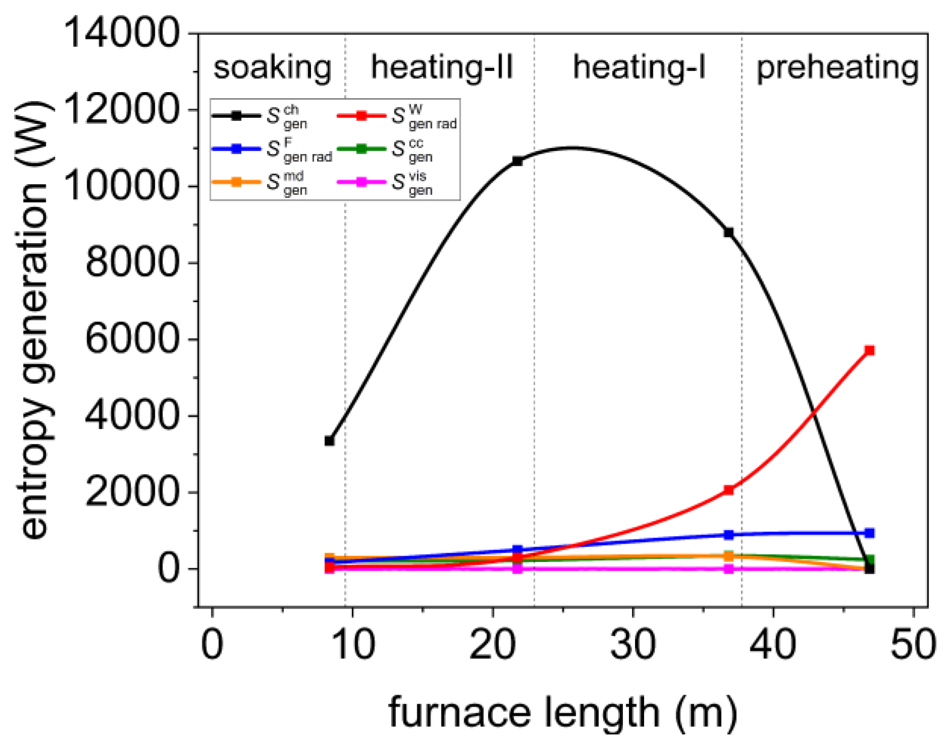
Integrating the entropy generation rate of different furnace zones by grid volume or area, the total entropy production along the length of the furnace can be archived, as shown in Figure 6. It can be seen that the total entropy generation of the combustion process is dominant, mainly distributed in the heating-I and heating-II zones. Next is radiative heat transfer entropy generation, mainly distributed in the preheating and heating-I zones. The total entropy generation of the conductive and convective heat transfer, mass diffusion, and viscous dissipation processes have little difference in each furnace zone. Compared with other entropy production, viscous dissipation entropy production is too small and can be neglected.
4. Discussions of Exergy Efficiency
4.1. The Energy Equilibrium and Exergy Equilibrium of the Furnace
According to the exergy equilibrium model in Section 2.3, the energy equilibrium and exergy equilibrium of the furnace hearth are obtained, as shown in Table 1 and Table 2, respectively.
The deviation between the exergy income and expenditure terms is 0.36%, and the deviation between the energy income and expenditure terms is 0.20%, proving the accuracy of the exergy equilibrium model. Combustion and radiative heat transfer primarily contribute to entropy generation.
In the exergy equilibrium of the furnace hearth, the total irreversible exergy loss accounts for 26.39% of the total furnace input exergy, in which the combustion process accounts for 16.43% and radiative heat transfer accounts for 8.47%. The irreversible exergy loss due to mass diffusion, conductive and convective heat transfer, and viscous dissipation processes are slight, accounting for 1.5% of the total input exergy. The first type of exergy loss accounts for 29.55%, in which the exergy taken away by water cooling accounts for about 9.45%, the exergy taken away by heat dissipation of the furnace wall accounts for about 5.07%, and the exergy loss taken away by the exhaust flue gas is about 29.43%. The exergy efficiency of the furnace hearth is 53.85%.
In the energy equilibrium of the furnace hearth, the energy loss caused by water cooling accounts for about 11.06%, the energy loss due to heat dissipation of the furnace wall accounts for about 5.66%, and the energy loss taken away by the exhaust flue gas is about 15.03%. The exergy efficiency of the furnace hearth is 44.06%.
A Sankey diagram of exergy flows and energy flows of the whole furnace considering the heat exchanger in the flue is shown in Figure 7a,b. The irreversible loss caused by the heat transfer temperature difference in the heat exchanger accounts for about 12.38% of the total flue gas exergy. The recovered exergy accounts for about 45.17% of the total flue gas exergy. The exhaust exergy accounts for 42.45% of the total flue gas exergy. Therefore, improving the heat recovery efficiency of the heat exchanger is an important measure to improve the energy efficiency of the whole furnace system.
Compared with the exergy balance, the exergy balance can reflect the proportion of each irreversibility loss in the furnace more finely. The exergy loss caused by irreversibility accounted for 26.39% of the total exergy input, primarily due to high entropy generation in the furnace. Therefore, irreversible losses due to entropy generation in the furnace should not be neglected when analyzing furnace energy efficiency and can be optimized by changes in the heating process.
4.2. Influence of Heating Parameters on Furnace Exergy Efficiency
The typical fuel mass flow rates of the heating-I, heating-II, and soaking zones are 0.8, 1.0, and 0.3 kg/s, respectively. The residence time in the furnace is 150 min, and the charging temperature is 25 °C. Keeping the other conditions unchanged and adjusting the residence time to 135, 150, 165, 180, and 195 min, respectively, the changes in entropy generation and exergy efficiency are shown in Figure 8a,b. As the slab residence time decreases, the discharge interval of the slab is short, and the steel heating curve will shift downward. The energy level difference between the high-temperature flue gas and the low-temperature slab increases and leads to a deterioration in the heat transfer state. The irreversible exergy losses in the furnace increase by 2.5%, while the exergy losses due to exhaust flue gas and heat dissipation are reduced by 5.8%. Thus, the total exergy efficiency of the furnace decreased by 3.3%. In addition, production also reduced from 330 t/h to 280 t/h. Therefore, fast-paced production is one of the main ways to save energy for the reheating furnace.
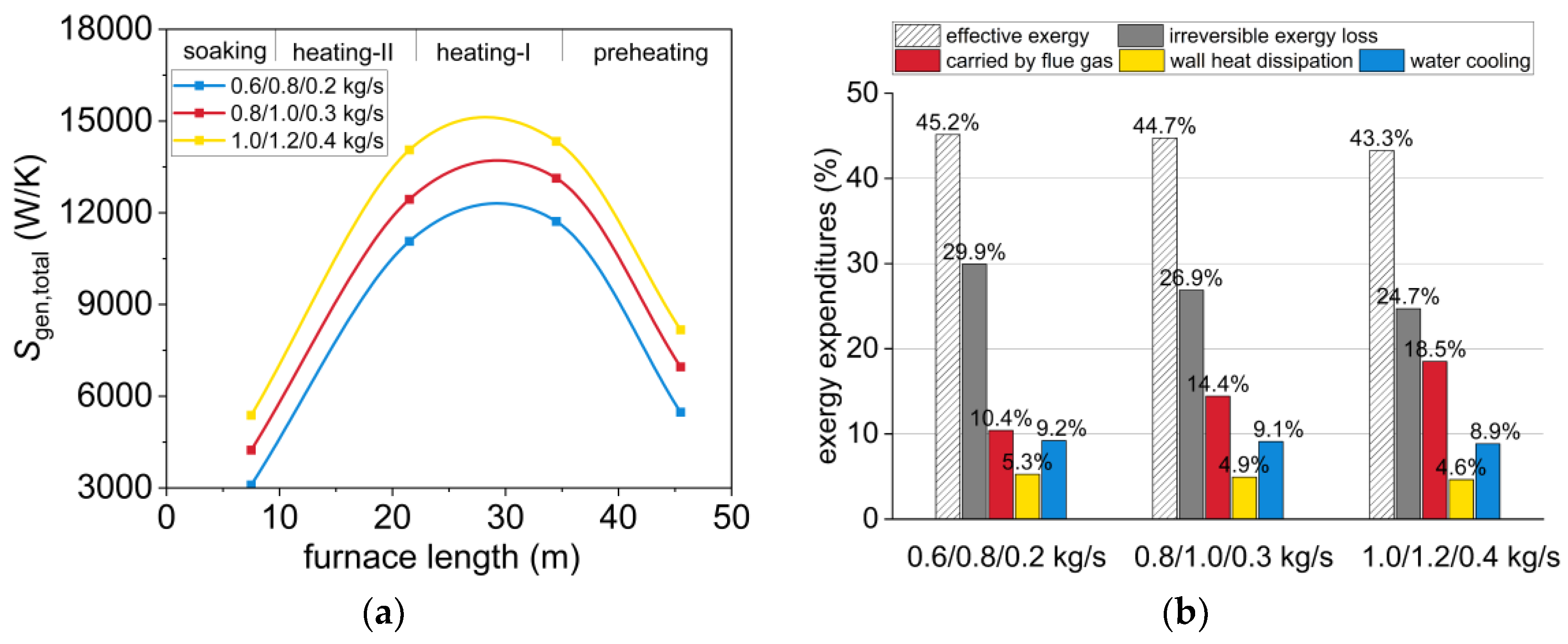
Similarly, keeping the other conditions unchanged and increasing the fuel mass flow rate of the heating-I, heating-II, and soaking zones to be 0.6/0.8/0.2 kg/s, 0.8/1.0/0.3 kg/s, and 1.0/1.2/0.4 kg/s, respectively, the changes in entropy generation and exergy efficiency are shown in Figure 9a,b. As mentioned earlier, fast-paced production is one way to save energy. However, this means an increase in fuel supply. For this furnace, the minimum total fuel flow rate is 1.6 kg/s, and the maximum total fuel flow rate is 2.4 kg/s. As the fuel flow rate is increased from the minimum to the maximum, the proportions of each exergy loss are significantly reduced. Among them, the exergy losses due to entropy generation, heat dissipation, and water cooling were reduced by 6.2%. Thus, the hearth efficiency should increase by 6.2%. However, the exergy loss taken away by exhaust flue gas increased from 10.4% to 18.5%, resulting in an 8.1% decrease in whole furnace exergy efficiency. The exergy recovery efficiency of the heat exchanger in the flue became the most important factor affecting the efficiency of the whole furnace. The heat exchanger should recover at least 2.9% of the exergy to achieve constant efficiency. The recovery ratio should be 0.029/0.081 = 0.36. Therefore, when selecting the heat exchanger of the heating furnace, the recovery efficiency should be considered higher than 36%.
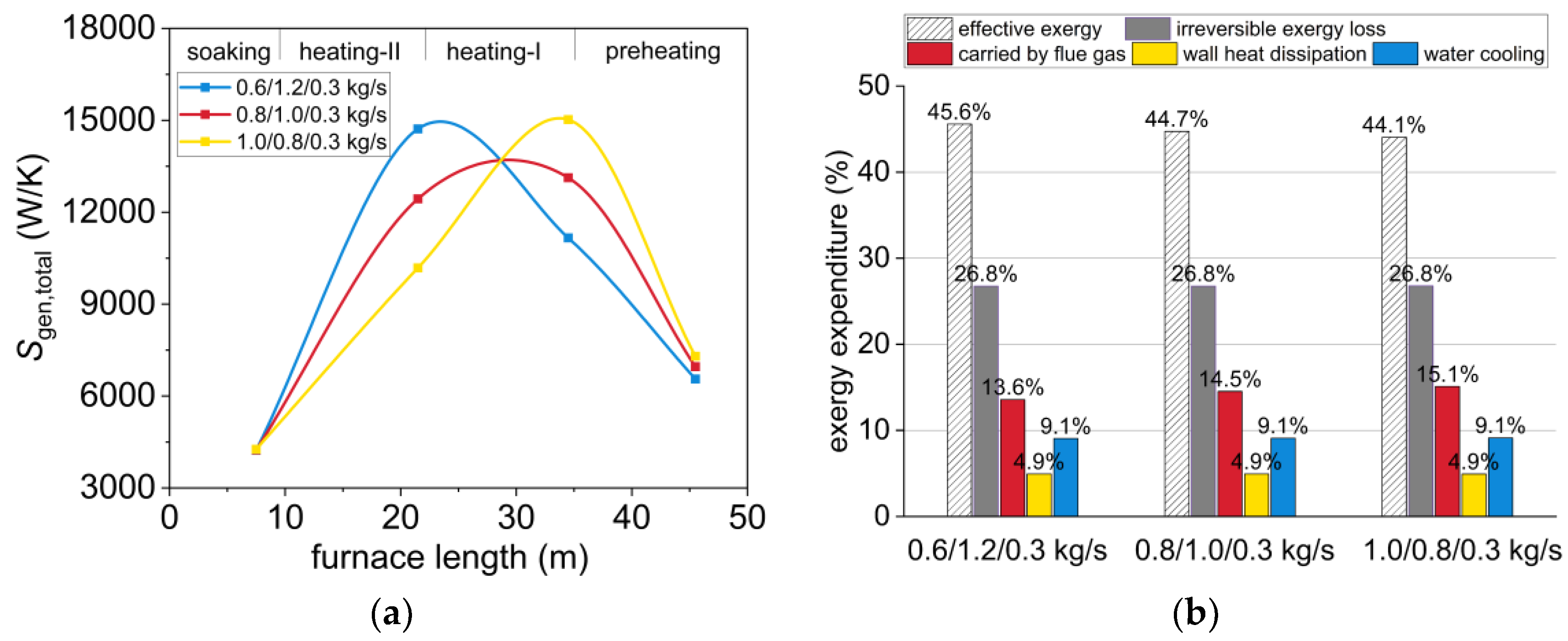
Similarly, keeping the total fuel supply of the whole furnace at 2.1 kg/s unchanged, adjusting the fuel flow distribution of the heating-I, heating-II, and soaking zones to be 0.6/1.2/0.3 kg/s, 0.8/1.0/0.3 kg/s, and 1.0/0.8/0.3 kg/s respectively, the changes in entropy generation and exergy efficiency are shown in Figure 10a,b. The variation in fuel allocation affects the entropy generation distribution in each zone, but the total entropy generation is almost unchanged. The proportions of exergy losses caused by irreversible processes, water-cooled, and wall heat dissipation are also unchanged. However, when the fuel flow rate in the preheating zone is high, the exergy loss taken by exhaust flue gas increases by about 1.5%. The furnace gaseous efficiency will decrease by 1.5%. Even the recovery rate of the flue heat exchanger can be 100%, only to ensure that the exergy efficiency does not decrease. Therefore, increasing the fuel mass flow rate in the preheating zone while decreasing it in the heating zone will cause more energy consumption.
5. Conclusions
This paper simulated the combustion, flow, and heat transfer in a walking beam reheating furnace by establishing a half-furnace model. The entropy generation rate distribution of different thermal processes was numerically calculated. The effect of slab residence time and fuel distribution in the furnace was studied to optimize the exergy efficiency. The results indicate that:
(1) Combustion and radiative heat transfer are the primary sources of entropy generation.
(2) Irreversible losses account for 26.39% of the total input exergy, in which the combustion process accounts for 16.43%, and radiative heat transfer accounts for 8.47%.
(3) Reducing the residence time by 60 min decreases irreversible exergy loss by about 2.5% but increases heat dissipation and exhaust exergy loss by 5.8%.
(4) Energy saving can only be achieved when the heat exchanger’s exergy recovery efficiency exceeds 36% under different fuel supplies.
(5) Keeping the total fuel supply unchanged, increasing the fuel mass flow rate in heating-I zone while decreasing it in heating-II zone results in a 1.5% decrease in exergy efficiency.
It should be pointed out that, due to the assumption of a uniform step forward of the slab and the simplification of the furnace structure during the numerical simulation, the furnace efficiency changes with the heating parameters will have a specific deviation from actual working conditions. However, it can still reflect the general law of energy use in the heating furnace. In future studies, the effect of slab vacancies in the furnace and fluctuations in slab temperature in the same zone on the heating parameters should be further analyzed. The optimization of the furnace structure and burners using the EGA method also has significance in improving the effect of complete combustion and optimal control of the furnace.
Author Contributions
Conceptualization, Z.J. and D.W.; methodology, Z.J. and D.W.; software, D.W.; validation, D.W. and Y.Z.; formal analysis, Z.J. and D.W.; investigation, Z.J. and D.W.; resources, Z.J.; data curation, D.W. and Y.Z; writing—original draft preparation, D.W.; writing—review and editing, D.W. and X.Z.; visualization, D.W. and Y.Z.; supervision, Z.J.; project administration, Z.J.; funding acquisition, Z.J. and X.Z. All authors have read and agreed to the published version of the manuscript.
Funding
This research was funded by the National Key Research and Development Program of China (2018YFB0605903) and the Fundamental Research Funds for the Central Universities (No., FRF–BD–20–09A).
Data Availability Statement
The data presented in this study are available on request from the corresponding author.
Conflicts of Interest
The authors declare no conflicts of interest.
References
- Tang, G.; Wu, B.; Bai, D.; Wang, Y.; Bodnar, R.; Zhou, C. CFD modeling and validation of a dynamic slab heating process in an industrial walking beam reheating furnace. Appl. Therm. Eng. 2018, 132, 779–789. [Google Scholar] [CrossRef]
- Mayr, B.; Prieler, R.; Demuth, M.; Moderer, L.; Hochenauer, C. CFD analysis of a pusher type reheating furnace and the billet heating characteristic. Appl. Therm. Eng. 2017, 115, 986–994. [Google Scholar] [CrossRef]
- Liu, Y.; Wang, J.; Min, C.; Xie, G.; Sunden, B. Performance of fuel-air combustion in a reheating furnace at different flowrate and inlet conditions. Energy 2020, 206, 118206. [Google Scholar] [CrossRef]
- Gu, M.; Chen, G.; Liu, X.; Wu, C.; Chu, H. Numerical simulation of slab heating process in a regenerative walking beam reheating furnace. Int. J. Heat Mass Transf. 2014, 76, 405–410. [Google Scholar] [CrossRef]
- Han, S.H.; Chang, D. Optimum residence time analysis for a walking beam type reheating furnace. Int. J. Heat Mass Transf. 2012, 55, 4079–4087. [Google Scholar] [CrossRef]
- Chen, D.; Lu, B.; Dai, F.; Chen, G.; Yu, W. Variations on billet gas consumption intensity of reheating furnace in different production states. Appl. Therm. Eng. 2018, 129, 1058–1067. [Google Scholar] [CrossRef]
- Feng, H.; Chen, L.; Liu, X.; Xie, Z. Constructal design for an iron and steel production process based on the objectives of steel yield and useful energy. Int. J. Heat Mass Transf. 2017, 111, 1192–1205. [Google Scholar] [CrossRef]
- Zhao, J.; Wang, J.; Yan, Q.; Ma, L.; Li, W. Energy-Saving Theory and Optimization Planning and Evaluation for the Steel-Rolling Reheating Furnace. Tianjin Daxue Xuebao (Ziran Kexue Yu Gongcheng Jishu Ban)/J. Tianjin Univ. Sci. Technol. 2020, 53, 763–770. [Google Scholar] [CrossRef]
- Rong, W.; Li, B.; Qi, F. Performance evaluation of a walking beam type reheating furnace based on energy and exergy analysis. Therm. Sci. 2021, 25, 4749–4760. [Google Scholar] [CrossRef]
- Bejan, A. A Study of Entropy Generation in Fundamental Convective Heat Transfer. J. Heat Transf. 1979, 101, 718–725. [Google Scholar] [CrossRef]
- Lior, N.; Sarmiento-Darkin, W.; Al-Sharqawi, H.S. The exergy fields in transport processes: Their calculation and use. Energy 2006, 31, 553–578. [Google Scholar] [CrossRef]
- Lou, C.; Zhang, Z. Experimental and numerical analysis of radiative entropy generation in industrial and boiler furnaces. J. Quant. Spectrosc. Radiat. Transf. 2019, 232, 27–34. [Google Scholar] [CrossRef]
- Pitchandi, K. Design and analysis of concentric tube heat exchanger using entropy generation minimisation. Int. J. Exergy 2014, 15, 276. [Google Scholar] [CrossRef]
- Arefian, A.; Abbassi, A.; Hosseini, R. Exergy analysis and optimisation of collector dimensions in a solar chimney power plant using entropy generation minimisation method. Int. J. Exergy 2014, 15, 328. [Google Scholar] [CrossRef]
- Wang, D.; Jiang, Z.; Zhang, X.; Li, X.; Xiang, Y. Numerical simulation and analysis of entropy generation and exergy equilibrium of the thermal process in a regenerative billet reheating furnace. Int. J. Exergy 2023, 42, 350–363. [Google Scholar] [CrossRef]
- Makhanlall, D.; Munda, J.L.; Jiang, P. Radiation energy devaluation in diffusion combusting flows of natural gas. Energy 2013, 61, 657–663. [Google Scholar] [CrossRef]
- Sciacovelli, A.; Verda, V.; Sciubba, E. Entropy generation analysis as a design tool-A review. Renew. Sustain. Energy Rev. 2015, 43, 1167–1181. [Google Scholar] [CrossRef]
- Liu, L.H.; Chu, S.X. Verification of numerical simulation method for entropy generation of radiation heat transfer in semitransparent medium. J. Quant. Spectrosc. Radiat. Transf. 2007, 103, 43–56. [Google Scholar] [CrossRef]
Figure 1.
Structure, mesh, and models. (a) The structure of the walking beam reheating furnace; (b) mesh results; (c) the contact heat conduction model between beams and the slab.
Figure 1.
Structure, mesh, and models. (a) The structure of the walking beam reheating furnace; (b) mesh results; (c) the contact heat conduction model between beams and the slab.

Figure 2.
Exergy equilibrium model of the furnace hearth and the whole furnace.

Figure 3.
Convergence process and experimental verification of slab temperature. (a) The average temperature distribution of slabs in the furnace; (b) the comparison between the simulated and the measured temperature data.
Figure 3.
Convergence process and experimental verification of slab temperature. (a) The average temperature distribution of slabs in the furnace; (b) the comparison between the simulated and the measured temperature data.

Figure 4.
Temperature and flow field of the furnace. (a) The temperature distribution of the medium; (b) the temperature distribution of the furnace wall; (c) the temperature distribution of typical cross-sections; (d) the velocity distribution of typical cross-sections.
Figure 4.
Temperature and flow field of the furnace. (a) The temperature distribution of the medium; (b) the temperature distribution of the furnace wall; (c) the temperature distribution of typical cross-sections; (d) the velocity distribution of typical cross-sections.

Figure 5.
The entropy generation distribution of different thermal processes. (a) Conductive and convective heat transfer; (b) viscous dissipation; (c) mass diffusion; (d) combustion; (e) radiative heat transfer in the medium; (f) radiative heat transfer on the solid surface.
Figure 5.
The entropy generation distribution of different thermal processes. (a) Conductive and convective heat transfer; (b) viscous dissipation; (c) mass diffusion; (d) combustion; (e) radiative heat transfer in the medium; (f) radiative heat transfer on the solid surface.

Figure 6.
Distribution of entropy generation in each furnace zone.

Figure 7.
A Sankey diagram of exergy flow and energy flow of the whole furnace considering heat exchanger in the flue. (a) Exergy flow; (b) energy flow.
Figure 7.
A Sankey diagram of exergy flow and energy flow of the whole furnace considering heat exchanger in the flue. (a) Exergy flow; (b) energy flow.

Figure 8.
Entropy generation and exergy efficiency change with residence time. (a) Entropy generation; (b) exergy efficiency.
Figure 8.
Entropy generation and exergy efficiency change with residence time. (a) Entropy generation; (b) exergy efficiency.

Figure 9.
Entropy generation and exergy efficiency change with fuel supply. (a) Entropy generation; (b) exergy efficiency.
Figure 9.
Entropy generation and exergy efficiency change with fuel supply. (a) Entropy generation; (b) exergy efficiency.

Figure 10.
Entropy generation and exergy efficiency change with fuel allocation. (a) Entropy generation; (b) exergy efficiency.
Figure 10.
Entropy generation and exergy efficiency change with fuel allocation. (a) Entropy generation; (b) exergy efficiency.


Table 1.
Exergy equilibrium of the furnace hearth.
| Category | Item | Value, kW | Percentage |
|---|---|---|---|
| Exergy income | 38,625.61 | 93.24% | |
| 437.09 | 1.06% | ||
| 2364.42 | 5.71% | ||
| Total | 41,427.12 | 100.00% | |
| Exergy output | 18,188.14 | 44.06% | |
| 6203.07 | 15.03% | ||
| 2092.48 | 5.07% | ||
| 3900.84 | 9.45% | ||
| 6783.32 | 16.43% | ||
| 0.64 | 0.00% | ||
| 250.06 | 0.61% | ||
| 365.86 | 0.89% | ||
| 906.30 | 2.20% | ||
| 2588.23 | 6.27% | ||
| Total | 41,278.94 | 100.00% | |
| Error | 148.18 | 0.36% |
Table 2.
Energy equilibrium of the furnace hearth.
| Category | Item | Value, kW | Percentage |
|---|---|---|---|
| Energy income | 38,625.61 | 84.38% | |
| 1772.45 | 3.87% | ||
| 5375.41 | 11.74% | ||
| Total | 45,773.47 | 100.00% | |
| Energy output | 24,698.86 | 53.85% | |
| 13,496.70 | 29.43% | ||
| 2596.49 | 5.66% | ||
| 5072.54 | 11.06% | ||
| Total | 45,864.60 | 100.00% | |
| Error | 91.13 | 0.20% |
Disclaimer/Publisher’s Note: The statements, opinions and data contained in all publications are solely those of the individual author(s) and contributor(s) and not of MDPI and/or the editor(s). MDPI and/or the editor(s) disclaim responsibility for any injury to people or property resulting from any ideas, methods, instructions or products referred to in the content. |
© 2024 by the authors. Licensee MDPI, Basel, Switzerland. This article is an open access article distributed under the terms and conditions of the Creative Commons Attribution (CC BY) license (https://creativecommons.org/licenses/by/4.0/).
Share and Cite
MDPI and ACS Style
Wang, D.; Zhang, X.; Zhu, Y.; Jiang, Z. Optimization of Exergy Efficiency in a Walking Beam Reheating Furnace Based on Numerical Simulation and Entropy Generation Analysis. Processes 2024, 12, 451. https://doi.org/10.3390/pr12030451
AMA Style
Wang D, Zhang X, Zhu Y, Jiang Z. Optimization of Exergy Efficiency in a Walking Beam Reheating Furnace Based on Numerical Simulation and Entropy Generation Analysis. Processes. 2024; 12(3):451. https://doi.org/10.3390/pr12030451
Chicago/Turabian StyleWang, Dijie, Xinru Zhang, Youxin Zhu, and Zeyi Jiang. 2024. "Optimization of Exergy Efficiency in a Walking Beam Reheating Furnace Based on Numerical Simulation and Entropy Generation Analysis" Processes 12, no. 3: 451. https://doi.org/10.3390/pr12030451
Note that from the first issue of 2016, this journal uses article numbers instead of page numbers. See further details here.