Article

Application of Life Cycle Assessment to Analysis of Fibre Composite Manufacturing Technologies in Shipyards Industry

by
Aleksandra Ziemińska-Stolarska
1,
Mariia Sobulska
1,
Monika Pietrzak
2 and
Ireneusz Zbiciński
1,*
1
Faculty of Process and Environmental Engineering, Lodz University of Technology, Wolczanska 213, 93-005 Lodz, Poland
2
Faculty of Chemistry, Lodz University of Technology, Zeromskiego 114, 90-543 Lodz, Poland
*
Author to whom correspondence should be addressed.
Processes 2024, 12(3), 461; https://doi.org/10.3390/pr12030461
Submission received: 3 February 2024 / Revised: 13 February 2024 / Accepted: 22 February 2024 / Published: 24 February 2024
(This article belongs to the Section Materials Processes)

Abstract

:
Life cycle assessment (LCA) is used to evaluate the environmental load of fibre composite manufacturing technologies in the shipyards industry in a frame of the Fibre4Yards (Horizon 2020) project. This paper is focused on the LCA of fibre-reinforced polymer (FRP) technologies used to produce all elements of the floating unit, i.e., the conventional vacuum infusion technology for the deck panel and adaptive mould process for superstructure panels, ultraviolet (UV) curved pultrusion process for the production of stiffeners, hot stamping technology for brackets, and three-dimensional (3D) printing and automatic tape placement (ATP) for pillars. Environmental impact was assessed based on standard indicators: Global Warming Potential, water consumption, and fossil resource scarcity. The results indicate that the total carbon footprint of analysed FRP technologies is mainly produced by the type of the materials applied rather than by the amount of energy consumed during the process.

1. Introduction

1.1. Fibre-Reinforced Polymers in Shipyard Industry

Nowadays, fibre-reinforced polymers (FRPs) are one of the most attractive materials for engineering application. In recent times, fibrous composites have become a strong alternative to steel in the construction industry [1]. The general advantages of FRP compared to conventional materials include high durability, cost-effective fabrication, excellent resistance to corrosion, fatigue, and fire [2,3], lighter weight, and lower maintenance costs [4]. Owing to their unique properties, FRP composites can be successfully used in the automobile [5], aerospace [6], and marine industry [7], especially for lightweight constructions [8].
The application of FRP in shipbuilding needs to qualify a specific marine standard. The main requirements are environmental stability, fracture toughness, resistance to cyclic fatigue, low creep, low relaxation, ease of joining and maintainability, as well as cost of investment and processing [7,9]. However, the production capacity in numbers of FRP ships does not achieve its full potential due to high total production costs. This limitation is due to the lack of automated procedures and the current semi-artisanal methods used in FRP shipbuilding. Therefore, meeting the shipyards sector’s requirements needs a transformation of traditional composite manufacturing processes. The Fibre4Yards (fibre composite manufacturing technologies for the automation and modular construction in shipyards—F4Y) Horizon2020 project brings together a unique multi-disciplinary consortium to successfully introduce advanced and innovative FRP manufacturing technologies in shipyards. The project aims to transfer, adapt, and combine targeted advanced production technologies from other competitive industrial sectors into a Shipyard 4.0 environment, which is interrelated thanks to Internet of Things technologies, and will be continuously supervised to guarantee high-quality processes using a digital twin of the shipyard [4,10,11]. The Shipyard 4.0 concept in the frame of the F4Y project includes the evaluation, assessment, and testing of the following technologies: the installation of the appropriate sensors and network (Internet of Things platform), implementation of improved data visualization tools, implementation of Machine Learning technologies, application of numerical tools for simulation to provide reliable processes, use of real-time analytics (retro feedback). Shipyard 4.0 envisions two types of integrations: horizontal integration on the three levels (production floor, across multiple production facilities of the same enterprise, and across the entire supply chain) and vertical integration, which aims to tie together all logical layers within the organization [11].
Fibre4Yards is a consortium of 13 partners from six European countries, i.e., from Spain: CIMNE, COMPASSIS, TSI, IRURENA; from Portugal: INEGI; from France: NAVAL GROUP, BUREAU-VERITAS, IRT JULES-VERNE, L-UP; from the Netherlands: CURVE-WORKS and 10XL; Lodz University of Technology from Poland; and INNOVATEKNEA from Hungary [11]. In the frame of the F4Y project, several advanced and highly automated FRP production technologies—adaptive moulds, Automatic Tape (Fibre) Placement (ATP/AFP), three-dimensional (3D) printing, curved pultrusion profiles, hot stamping, innovative composite connections—were considered [11].
The real scale demonstrator manufactured in the frame of the F4Y project consists of a deck panel with stiffeners manufactured by NAVAL GROUP (Nantes, France) applying conventional vacuum infusion technology, superstructure panels produced by CURVE-WORKS (Alphen aan den Rijn, The Netherlands) using the adaptive mould process, stiffeners of a superstructure manufactured applying the ultraviolet (UV) curved pultrusion process (Robtrusion®) by IRURENA (Azpeitia, Spain), hot stamping brackets produced using hot stamping technology by INEGI (Porto, Portugal), and pillars produced by 10XL (Rivierdijk, The Netherlands) via 3D printing and ATP/AFP. Figure 1 shows the schematic illustration of the final demonstrator.
Environmental load of particular technologies was determined by the life cycle assessment (LCA) technique. The environmental impact of the materials and manufacturing technologies, evaluated based on an LCA, was taken into consideration during the design of the ship demonstrator [11].
The presented paper is focused on the LCA of FRP technologies used to produce all elements of the demonstrator, i.e., the conventional vacuum infusion technology for the deck panel and adaptive mould process for superstructure panels, UV curved pultrusion process for the production of stiffeners, hot stamping technology for brackets, and 3D printing and ATP/AFP for pillars.

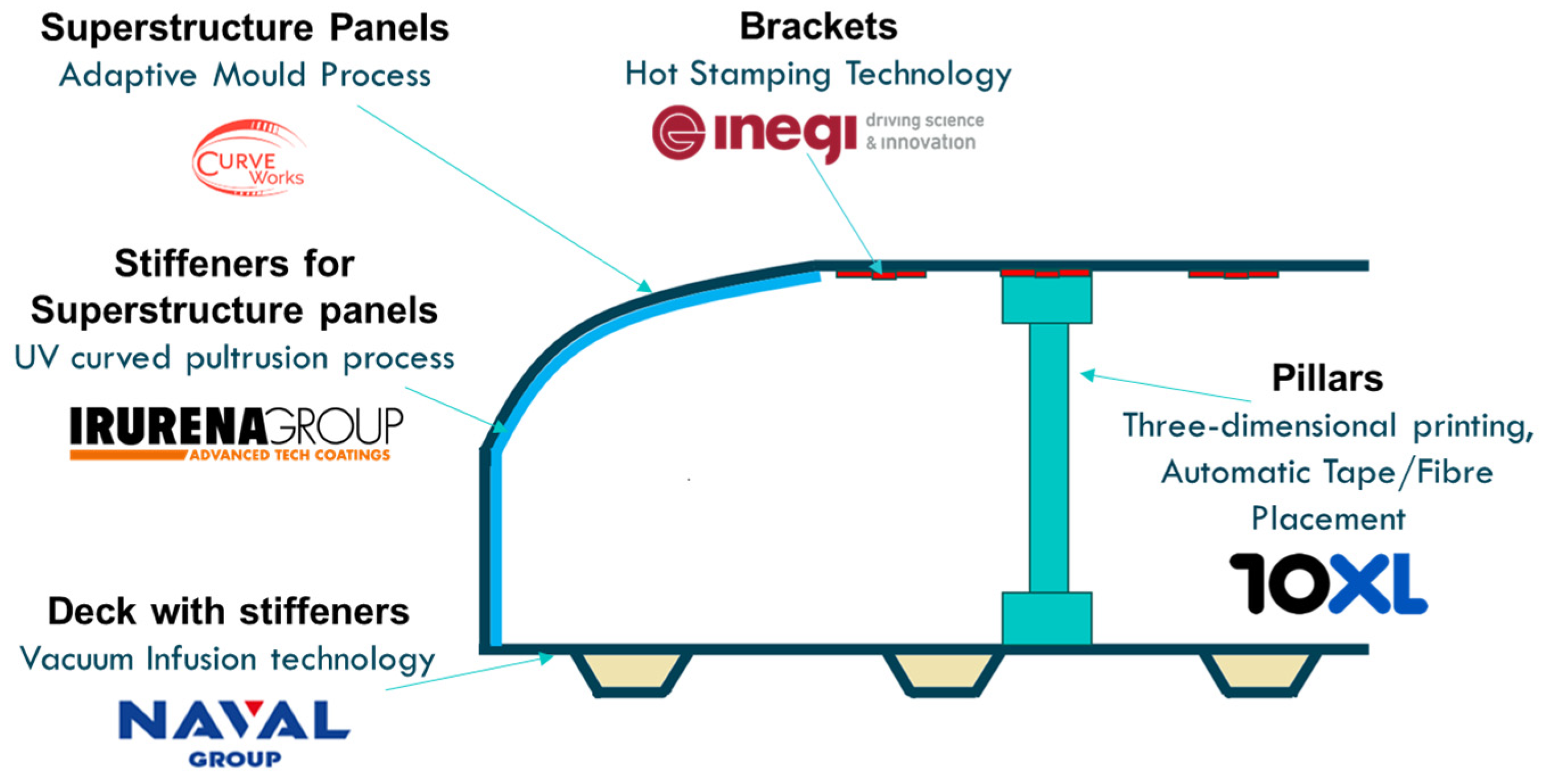
1.2. Advanced Manufacturing Processes for Shipyard Composites

Hot stamping technology is used for the production of elements of the lightboat by the Institute of Science and Innovation in Mechanical and Industrial Engineering (INEGI) [12]. The technology was patented by a Swedish company in 1977, as a process for saw blade and lawn mower blade production [13]. Car doors and secondary automotive structures such as Suspension Arms and brackets and Aeronautic Clips and brackets are among many examples of hot stamped parts. Hot stamping technology follows three main steps: FRP lay-up, press consolidation, and stamp forming. The process begins with prepreg uncoil by the automatic tape lay-up process and spot welding. Afterward, the blank is moved on the die to be a two-dimensional shape formed by the application of heat and pressure in a flat plate hot-press. Finally, the previously melted component is heated by an infrared heater and pressed to a 3D shape. In the stamp forming step, the interaction between the hydraulic press and the materials forces the component to achieve the designed geometry. After the forming of the defined shape, the part is quenched by cooling in the stamping press auxiliary cooling system. An industrial production line requires the automatic production of hot stamping with transferring systems of the formed part between particular steps [14]. Hot stamping has a number of advantages, such as a clean production environment and application to a wide range of materials. The main limitations of hot stamping technology are part size and slow cooling rates.
The second technology studied in the Fibre4Yards project is the UV curved pultrusion process (Robtrusion®), proposed by IRURENA Group [15]. The concept of pultrusion was developed in the United States of America during the 1900s [16], dedicated to curve composite profiles. The basic pultrusion operation consists of the following steps: a fibre reinforcement, resin impregnation bath, forming and curing die, pulling and cutting zone [17]. In the first stage, the reinforcements are pulled from the creel to the resin bath. Resin cures inside the die, providing the strength of the composite and resistance to environmental factors. Then, the impregnated reinforcements are pulled into the mould, which is only used to shape the cross-section of the profile. After that, the profile is cured by UV radiation emitted by the UV source. While this occurs, the profile is shaped with the robot arm, which grips the profile and pulls it, following a specific geometry required for the profile. The last step is to cut the profile manually. The energy of UV light is an alternative fast-curing method and can overcome the main limitations of the traditional pultrusion process [18]. The pultrusion process is characterized by high stability and high output, but applications of the process are limited to transparent materials, and thin single cross-sectional-shape products [19].
The Dutch company 10XL [20] developed in the frame of the Fibre4Yards project two technologies: ATP/AFP and 3D printing. ATP is one of the most versatile multi-layered composite forming processes. ATP consists of placing unidirectional thermoplastic tape on a substrate, and the application of heating followed by pressure. The tapes can be laid in various directions to produce a multi-oriented surface. Different heat sources can be used, e.g., laser, IR, hot gas, or air. The tool is moved by a robot, fusing the tape onto the thermoplastic surface. After a line, the tool cuts the tape to start over. The tape is mechanically forwarded to the pressure wheel. Currently, thermoplastic panels or sheets are mainly used in aerospace parts like aircraft wings [21]. Each ply can be placed at different angles, so the ATP process allows the production of highly customized parts. The limitations of technology are related to robot speed, machine dimensions, tape thickness, width, heat-source power.
A second technology reported by 10XL is 3D printing. 10XL specializes in extra-large three-dimensional objects by using its proprietary large-scale hybrid printers. Nowadays, 3D printing, also known as additive manufacturing, plays a crucial role in medical [22], electrochemical [23], architecture, aerospace, and automotive designs [24]. One of the main advantages of additive manufacturing over subtractive manufacturing, where three-dimensional objects are constructed by cutting material away from a solid block of material, is a lower amount of waste generated in 3D printing, because material is deposited layer by layer and is not cut away. Technology is based on the principle of layered manufacturing through positioning the print head in defined directions to overlap materials layer by layer. Several varieties of 3D printing technologies have been developed [25]. In the Fibre4Yards project, the process begins with preparing the material for printing. Thermoplastic granules are fed via a hopper loader into the extruder’s barrel. The extruder processes the molten polymers via a heated hose towards a heated nozzle mounted on a 6-axis industrial robot. Later, it is mounted on a track, and can move in a freeform manner in all directions. A 3D printing design is generated using appropriate software under computer control. While the robot is moving in a layered sequence, the nozzle leaves a bead of polymer on top of a previous layer where it fuses together and solidifies. The process limits include machine dimensions, extruder throughput, robot speed, or cooling rate. Compared to alternative technology, the production of parts by 3D printing requires the raw materials only needed for the printing parts, with minimum waste. Often the raw materials are recycled.
In the Fibre4Yards project, the Curve Works company [26] presented alternative solutions in the adaptive mould process to create curved shapes from 3D drawings with a high surface quality. This technology is already successfully applied to the production of large moulds built up of panels and large curved loaded structures such as a superstructure and hulls of ships. There are three main steps in the process: engineering, production, and assembly. At first, the structure is split into manufacturable panels within a 3D Computer-Aided Design program. The panels are engineered for strength, stiffness, minimal material waste, and panel assembly methodology. The Computer-Aided Design program generates files for the adaptive mould for each individual panel. When the file is chosen, the adaptive mould shapes itself automatically to the designed shape. After curing, the panel is released, the mould returns to its flattened shape, and the next panel is chosen. A simple jig is required to support the panels during the assembly process. The panels are assembled together at their joints using adhesion and in situ curing.
Naval Group (France) applied conventional vacuum infusion technology to produce a deck panel with stiffeners. Vacuum infusion uses reduced pressure to force resin to fill in the composite laminate [27]. The most commonly used composite in vacuum infusion technology is sandwich, which includes two stiffeners made from fibre-reinforced laminates of glass or carbon and the lightweight core made from the foam or balsa wood. The first step includes the fixing of fibres and a core material on the mould, and in the next step, a resin feed line is installed, including a vacuum line, valves, and the vacuum bag, which need to be properly sealed. Under-pressure conditions allow for compact joining of all the material layers: both fibre skins and the balsa core, as well as the complete impregnation of layers by epoxy resin and the elimination of any air voids from the laminate structure [28].
Advantages and disadvantages of particular technologies applied in the F4Y project are summarized in Table 1.
Apart from the technologies developed in the FIBRE4YARDS project, laser cutting is another promising manufacturing method in shipyard composites. Laser cutting is a highly versatile and efficient manufacturing process that offers exceptional precision, versatility, and cost-effectiveness for a wide range of applications across various industries. There are several laser sources of cutting equipment such as CO2, solid-state, fibre, and YAG lasers [29]. CO2 laser cutting is commonly used for thermoplastic materials where CO2 lasers generate a high-powered infrared beam by exciting CO2 gas molecules with electricity. Since CO2 laser cutting is a non-contact process, there is no tool wear, reducing maintenance costs and ensuring consistent cutting quality over time. It also minimizes the risk of damage, distortion, or contamination to the material being cut [30]. Caiazzo et al. examined optimal parameters for CO2 laser cutting of polycarbonate (PC), polypropylene (PP), and polyethylene (PE). It was proved that employment of powerful CO2 laser sources is not necessary to achieve a good quality of the cut [31]. Der et al. investigated the effects of a number of cutting parameters (i.e., material type, power, and cutting speed) on the key output (i.e., kerf width and heat-affected zone) in CO2 laser cutting of thermoplastic materials [32].

1.3. LCA for FRP Technologies

In light of environmental issues, LCA becomes a key methodology to evaluate impact indicators throughout an entire life cycle of materials, products, or technology. The LCA approach was successfully adopted by numerous projects as a decision making tool at the design stage [33] as well as for the redesign and replacement of conventional materials to reduce environmental load. Redesign refers to activities that are aimed to reduce environmental load of a particular stage of a product’s life and future post-use stage [34]. The comparative LCA analysis gives measurable indicators in various impact categories to indicate the manufacturing options with low environmental load [35].
The aim of this study was to evaluate environmental load of advanced and highly automated FRP production technologies developed in the frame of the Fibre4Yards project using the LCA method. In the literature, there are studies on the LCA analysis of ship building technologies that use conventional materials like steel [36] and aluminium and steel [37,38]; LCA of an entire ship built from composite materials such as glass fibre and resin [39]; comparative LCA study for a ship built from aluminium and composites like glass fibre or carbon fibre with vinyl ester resin [40]. To the best of our knowledge, in the literature, there are no studies regarding the comparison of novel advanced FRP technologies dedicated to shipyard application in terms of their environmental profile. An additional benefit of our study is direct cooperation with producers regarding data collection in terms of materials and energy used.

2. Materials and Methods
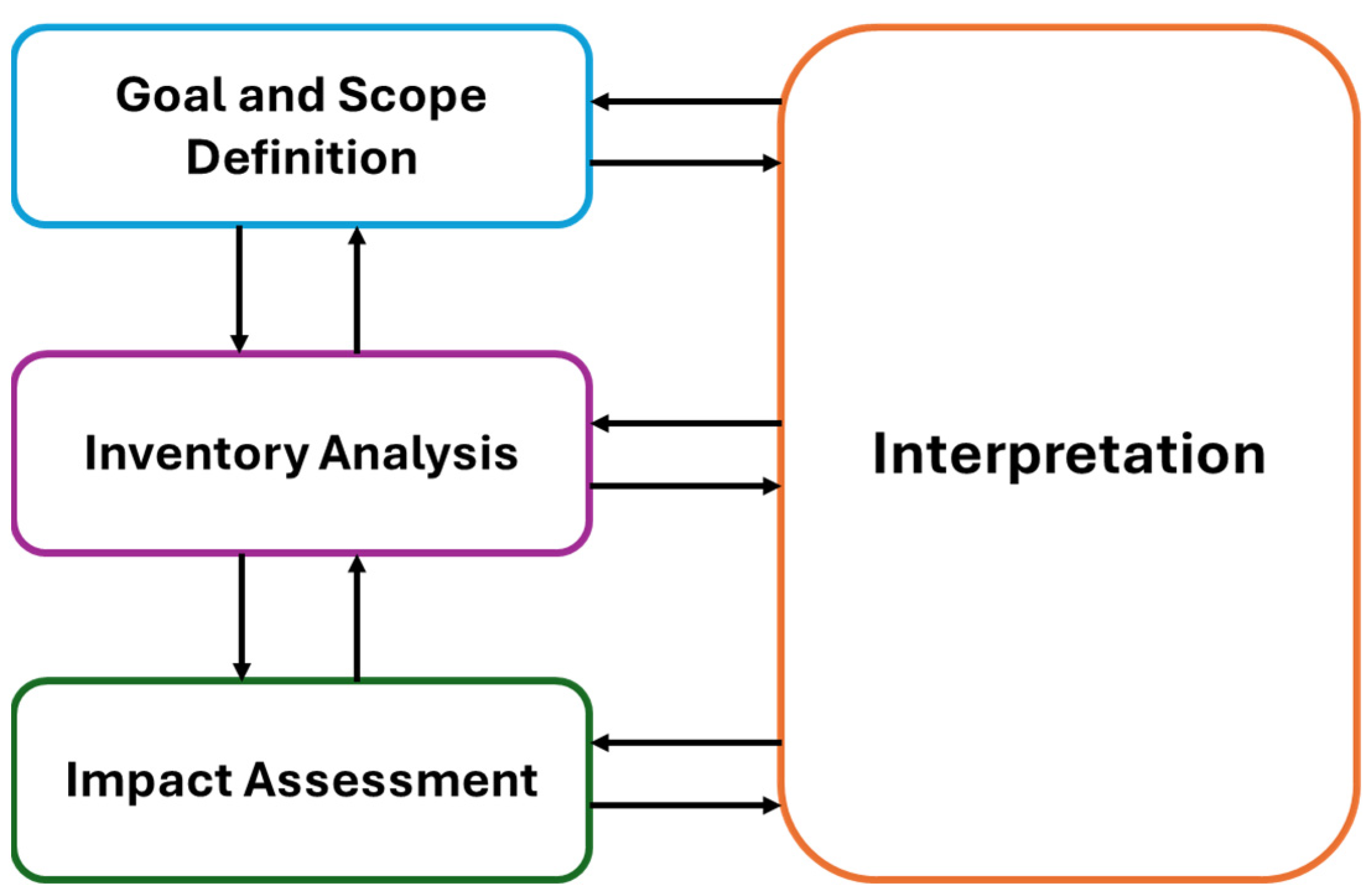
2.1. Methodology

The LCA is a science-based approach of assessing the potential environmental impacts of products or services during the entire life cycle. The methodology consists in carrying out an assessment of natural resources and raw material consumption, energy consumption, and emissions into the environment (emissions to air, water, and soil), for each unit process of the system under study.
First, all inputs and outputs (material and energy flows, both extracted from the environment and released into it) are inventoried for each life cycle phase. Then, data are aggregated to assess environmental impact indicators. Results are therefore presented through several environmental impact categories, depending on the selected method.
The LCA methodology allows for the comparison of different materials and to identify pollution transfers (so-called “burden shifting”) from one type of impact of the natural environment to another, or from one life cycle stage to another, between two different scenarios of the same system, or between two different systems. Thus, LCA can be used in the context of a “design for the environment” approach or for support to decision making.
LCA analyses need to be conducted according to the requirements of International Standards: ISO 14040 (Environmental Management—Life cycle assessment—Principles and Framework) [41] and ISO 14044 (Environmental Management—Life cycle assessment—Requirements and guidelines) [42].
A complete LCA, consistent with ISO standards, is composed of four interrelated phases (Figure 2):
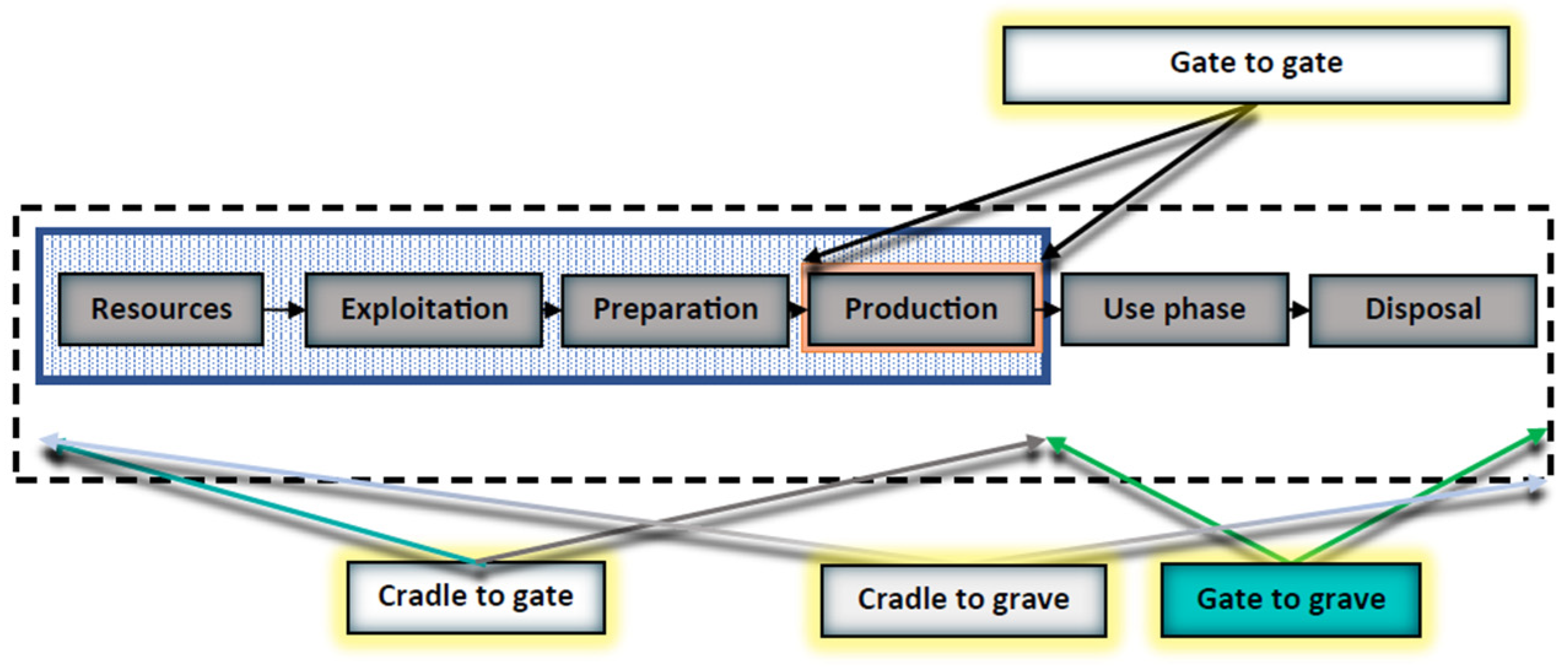
  • The Goal Definition and scope, which define and describe the product or process: establish the context in which the assessment is to be made and identify the boundaries and environmental effects to be reviewed for the assessment. An important part of the goal and scope is the definition of a functional unit, which is a measure of the performance of the studied system or product/process and it provides a reference to which the inputs and outputs can be related. The purpose of the functional unit is to provide reference to which all inputs and outputs are related. Another aspect within the goal and scope stage is to define the system boundary. A system boundary is the set of criteria that determines which unit processes, inputs, outputs, and impacts are considered in an LCA. Four different system boundaries can be distinguished (Figure 3):
    • Cradle-to-grave is the full LCA starting from the extraction of raw materials (‘cradle’) to the use and disposal phase—landfill, incineration (‘grave’).
    • Cradle-to-cradle is a particular kind of cradle-to-grave approach, where the end-of-life disposal step for the product is a recycling process. It is a method used to minimize the environmental impact of products by employing sustainable production, operation, and disposal practices, and it aims to incorporate social responsibility into product development.
    • Cradle-to-gate is an assessment of a partial product life cycle from resource extraction (cradle) to the gate of the factory (i.e., before it is transported to the consumer).
    • Gate-to-gate is a partial LCA method, looking at only one value-added (unit) process in the entire production chain. Gate-to-gate modules may also be linked later in their appropriate production chain to form a complete cradle-to-gate evaluation [43].
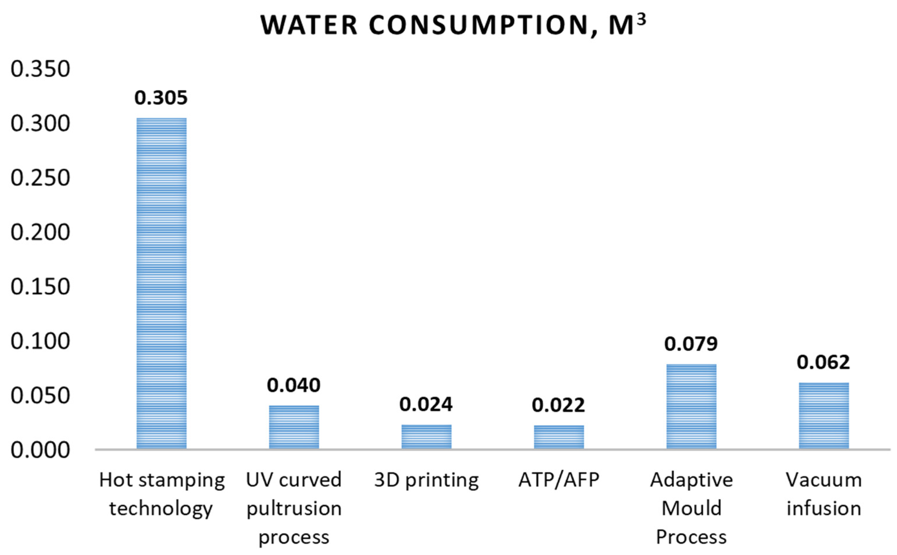
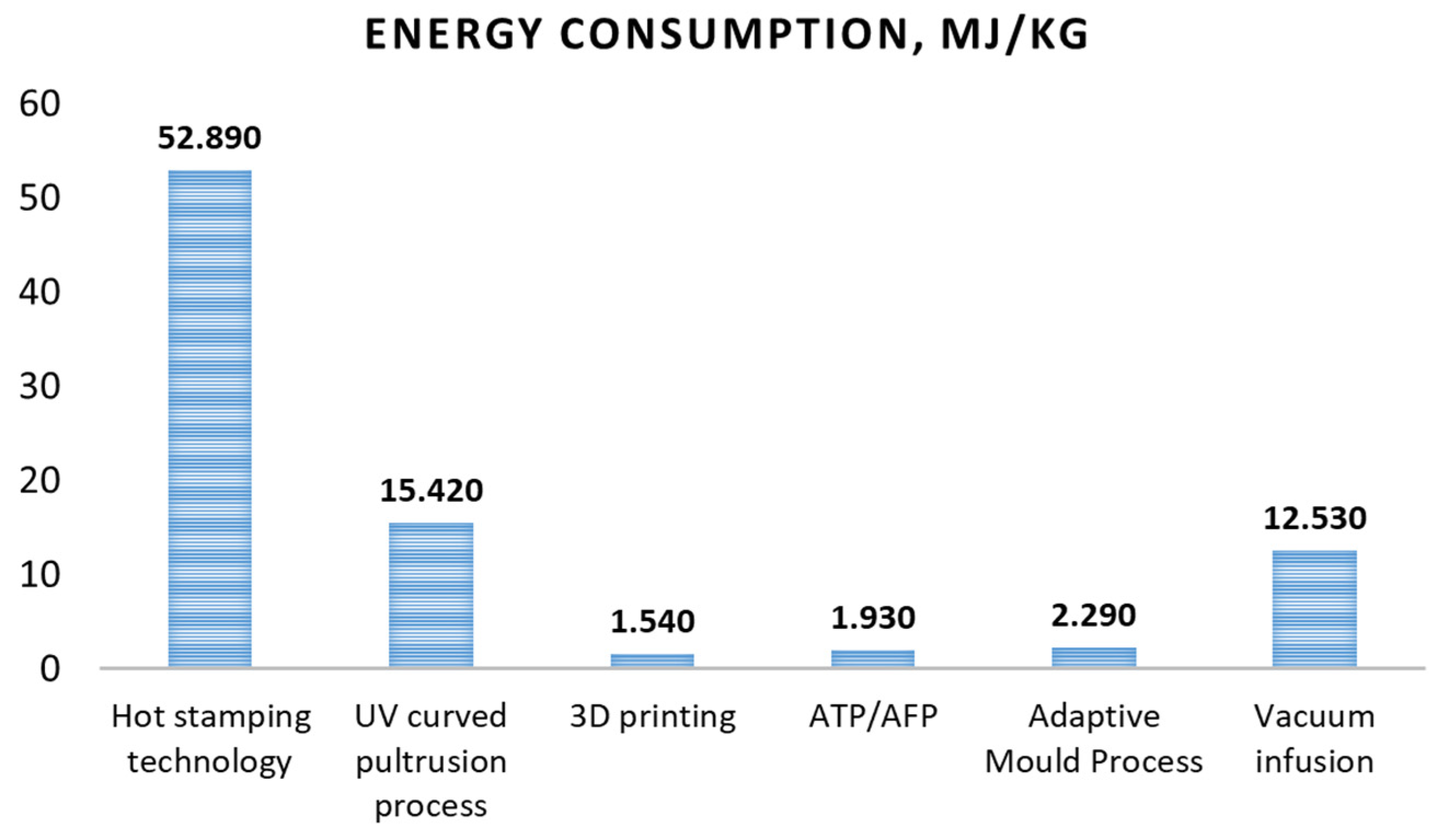
  • The inventory analysis: This step helps with identifying and quantifying energy, water, and raw material usage and environmental releases (e.g., emissions, solid waste disposal, waste water discharges). This is a technical process of collecting data in order to quantify inputs and outputs of the system.
  • The impact assessment assesses the potential effects of energy, water, and material usage and the environmental releases identified in the inventory analysis. Results are therefore presented through several environmental impact indicators, like climate change, ozone depletion, human toxicity, fossil fuel consumption, eutrophication, and cumulative energy demand, and carbon-related indicators including carbon dioxide equivalent (CO2-eq.).
  • The Interpretation step evaluates the results of the inventory analysis and impact assessment to select the preferred product, process, or service with a clear understanding of the uncertainty and the assumptions used to generate the results.

2.2. Software

Depending on the selected LCA software (i.e., SimaPro, GaBi, Umberto), the impact assessment methods differ. Impact assessment methods can
(a)
focus on a single impact or environmental footprint such as the carbon footprint or the water footprint;
(b)
include several impact categories such as climate change, human toxicity, land use, water consumption, fossil resource scarcity, etc.
Among the most commonly used methods are
  • IPCC (International Panel on Climate Change) 2021, developed by the International Panel on Climate Change. This single-issue method lists the climate change factors of IPCC with a timeframe of 100 years and expresses the LCA results in terms of kg CO2-eq.
  • ReCiPe 2016, developed by the Dutch research institute of the National Institute for Public Health and the Environment, Radboud University Nijmegen, Leiden University, and Pré Consultants in 2008. It is a midpoint and an endpoint method, and it considers three different cultural perspectives: individualist, hierarchist (H), and egalitarian. The method assesses several midpoint impact categories (e.g., Global Warming Potential (GWP), water consumption, fossil resource scarcity, etc.) and the three areas of protection: human health, ecosystem quality, and natural resources at the endpoint level.
In the presented paper, both methods are used and results of the LCA analysis are presented in the next section.

2.3. Materials and Energy Consumption

The functional unit of this study is 1 kg of the element manufactured by different FRP technologies to produce the final demonstrator. The inventory data for each technology included all the materials and consumables as well as energy consumption and are presented in Table 2, Table 3, Table 4, Table 5, Table 6 and Table 7. Table 2 shows inventory for hot stamping technology. Two materials, polypropylene and carbon fibre, have the highest weight fraction in total materials used, about 99% altogether, with the relation of polypropylene to carbon fibre weight at about 1 to 1.08. During the hot stamping process, the energy is consumed for the spot welding, hot plate press pump, hot plate press heater, press auxiliary cooling system, blank holder system, infrared oven, and press. The Ecoinvent database does not include carbon fibre material, but only “carbon-fibre-reinforced plastic injection moulding” with a GWP 100 value of 82.6 kg CO2-eq per kg, which is significantly higher than values reported in the literature for unprocessed carbon fibre production: from 19 [44] to 32 [45] kg CO2-eq per kg of carbon fibre. Therefore, the production stage of carbon fibre was simulated based on literature data [46], and the inventory for a 1 kg production of carbon fibre is also included in Table 2.
Table 3 shows inventory for the UV curved pultrusion process. The share of about 95% in total material weight has glass fibre and UV formulation, with a glass fibre to UV formulation weight ratio of 1 to 0.67. For UV curved pultrusion, the main energy consumers are two UV sources, the robot arm and gripper.
Inventory for ATP/AFP technology is presented in Table 4. During the process, two main materials with significant weight fractions are polypropylene and glass fibre with mass ratio 1 to 1.5. Energy inventory includes electricity consumption by the ATP/AFP machine.
Inventory for 3D printing is presented in Table 5. Polypropylene and glass fibre are main materials with the largest share in total material weight, and energy consuming stages are heating up and standby, extruding, robotic arm operation, and heating.
Table 6 shows the inventory for the adaptive mould process, where three materials were used: glass fibre, epoxy resin, and polyurethane with weight ratio 1:0.5:0.5. During the process, electricity is consumed for heating, shaping, and cutting of the foam core as well as for shaping the mould for infusion and curing and for heating/curing.
The materials and energy consumed for the vacuum infusion process are presented in Table 7. The most significant contribution to the total material weight was glass fibre and epoxy resin and in terms of energy consumption, the most important equipment was the oven for balsa wood curing at 40 °C and the fan heater for post curing at 50/60 °C.

3. Results

3.1. Hot Stamping Technology

Figure 4 represents the GWP impact from the production of hot stamping brackets applying hot stamping technology. An overall carbon footprint to produce 1 kg of brackets by hot stamping technology was 30.29 GWP, kg CO2-eq. The maximum impact was from the carbon fibre production—23.41 kg CO2-eq—which accounts for 77.30% of contribution to the total carbon footprint. The production of carbon fibre has a high level of CO2 emissions due to an enormous amount of energy consumed during the production stage, and the estimation revealed that carbon fibre production consumes 14 times more energy than conventional steel production [47,48,49]. In the production process, the precursor, for instance, polyacrylonitrile, is first oxidized at a temperature of 200–300 °C, then carbonized at a temperature of 1000–1700 °C in a nitrogen atmosphere [48]. The energy intensity of chemical processes at such extreme temperatures is very high; thus, the energy requirement for carbon fibre production from different sources is estimated to be in the range from 9.62 MJ per kg of carbon fibre (calculated value) up to 478 MJ per kg of carbon fibre (data from the producer) [50]. Data presented in the inventory table (Table 2) show that the mass of two materials, i.e., carbon fibre (0.52 kg) and polypropylene (0.48 kg), does not differ significantly; however, their contribution to the total carbon footprint is incomparable: 77.30% for carbon fibre and only 3.61% for polypropylene. The electricity consumption for hot stamping technology generated the emission of 5.78 kg CO2-eq (19.08%), where the highest contribution had energy required for the hot plate press pump and hot plate press heater (3 kWh and 10.5 kWh). It is also worthwhile to mention that in the F4Y project, the hot stamping process was performed at the laboratory scale, where manufacturing of each item required preliminary heating up of the press plate. In case hot stamping is applied at the industrial scale, the press is heated up only once to produce several items, which will reduce the energy consumption of the process per kg of the final product produced.
In other categories, carbon fibre also has the highest contribution, 79.38% for water consumption and 76.00% for fossil resource scarcity, which is caused by high electricity consumption during the carbon fibre production stage.

3.2. UV Curved Pultrusion Process (Robtrusion®)
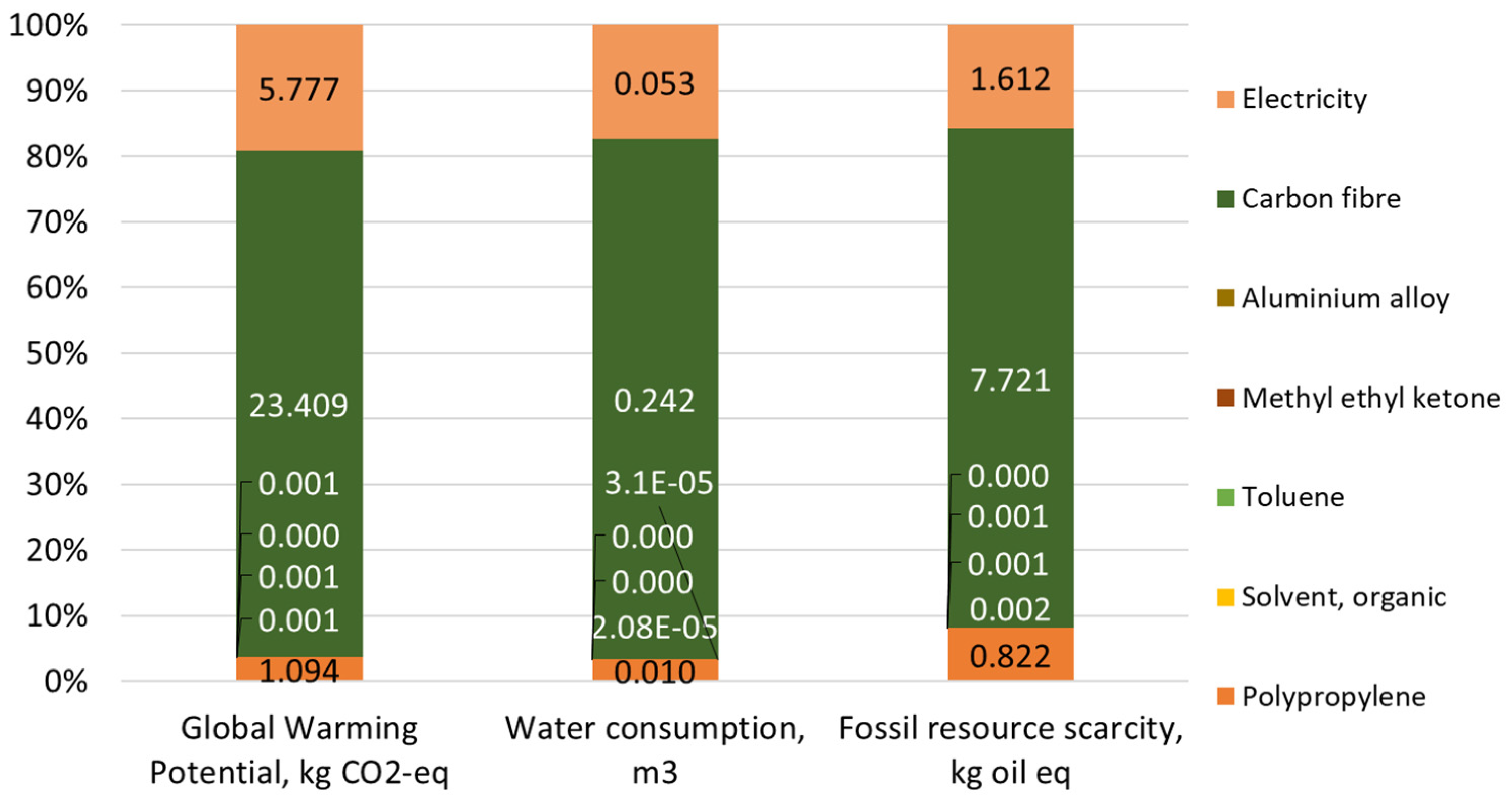
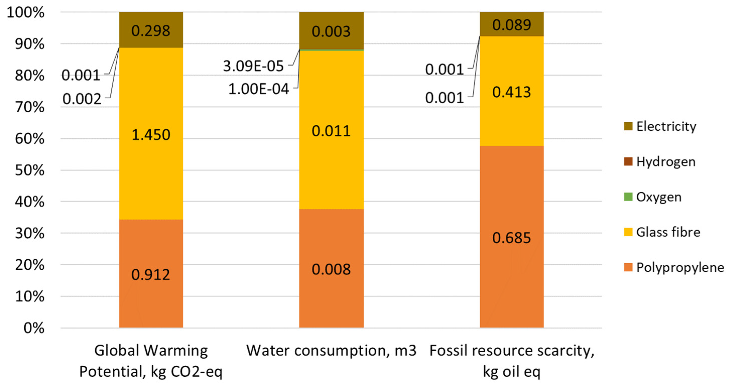
The UV curved pultrusion process generated in total 4.34 kg CO2-eq for the production of 1 kg of stiffeners for superstructure panels (Figure 5). The highest impact on the carbon footprint was caused by glass fibre production, which accounts for 42.27% of total carbon emissions. Based on the data obtained from two glass fibre producers, Owens Corning (Toledo, OH, USA) and Vetrotex (Aachen, Germany), the energy consumption of glass fibre production was determined as 12.58 MJ/kg (Owens Corning) and 32.0 MJ/kg (Vetrotex) [51,52]. Polyester resin, which accounts for about 37% of total weight of materials used for the production of stiffeners, generated 26.99% of total carbon dioxide emissions. In terms of the water consumption impact category, the effect of glass fibre was lower, i.e., 26.23% of total water consumption compared to polyester resin (52.24% of total water consumption). In terms of the fossil resource scarcity index, glass fibre contribution presents 33.91% of the total impact, and the share of polyester resin contribution reached a value of 44.43% of the total impact.

3.3. ATP/AFP

In the ATP/AFP technique, the extraction of raw materials and manufacturing of glass fibre and polypropylene together are responsible for almost 90% of total carbon emissions: glass fibre—54.45% and polypropylene—34.25% (Figure 6). Half of total water consumption for the ATP/AFP process is related to raw material extraction and manufacturing of glass fibre. Korol et al., 2019, reported that the main contributors to glass fibre water consumption were applied raw materials, e.g., silica, aluminium oxide, boric acid, clays, fluorite, and lime (74% in total), and the use of electricity, which accounts for 23% of the water footprint [53]. Only in terms of fossil resource scarcity the highest contribution was caused by raw material extraction and the production of polypropylene. Polypropylene is manufactured by the polymerization of the propylene monomer, which is obtained from crude oil; for example, to produce 1 kg of polypropylene, 1.32–1.66 kg of crude oil is required.

3.4. Three-Dimensional Printing

The GWP impact category for 3D printing technology was evaluated on 2.66 kg CO2-eq. As for previously discussed technologies, the highest contribution to carbon emissions was due to the production of materials used, such as glass fibre (27.22%) and polypropylene (51.75%), Figure 7. For 3D printing, the impact of polypropylene in all impact categories, GWP, water consumption, and fossil resource scarcity, was higher than for glass fibre due to the mass of materials used. The mass of polypropylene applied to produce 1 kg of 3D printed pockets was more than two times higher than the mass of glass fibre (0.605 and 0.3 kg, respectively). Water consumption for polypropylene production was 0.013 m3, which represents 53.84% of total water consumption. During manufacturing of polypropylene, the main factors that contribute to high water consumption are the use of electricity in the polymerization process and the production of propylene from crude oil [53]. The contribution of electricity consumption to the total carbon footprint of 3D printing does not exceed 8.93%.

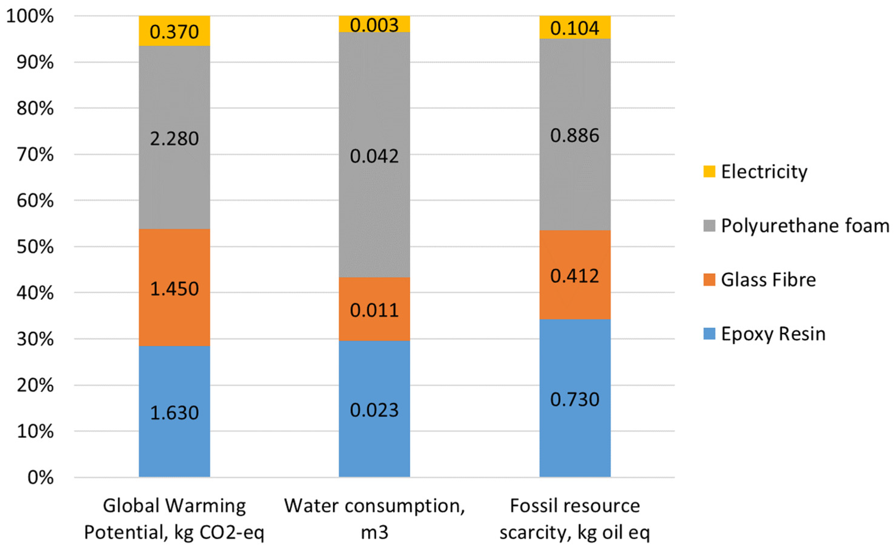
3.5. Adaptive Mould Process

The adaptive mould process generated in total 5.73 kg CO2-eq emissions per 1 kg of superstructure panel produced. Polyurethane foam was found to contribute the most, resulting in 2.28 kg CO2-eq emitted, which accounts for more than one third of the total contribution. The main substrates for polyurethane foam production are polyol and an isocyanate component, whose synthesis requires such raw materials as crude oil, natural gas, and sodium chloride; moreover, the production of 1 kg of polyurethane foam requires an energy input of 55 MJ/kg [54]. The next materials with a high share in the total carbon footprint are epoxy resin (1.63 kg CO2-eq) and glass fibre with a comparable impact of 1.45 kg CO2-eq emitted. The impact of electrical energy consumption is estimated to account for 6.5% of the total carbon footprint (Figure 8).

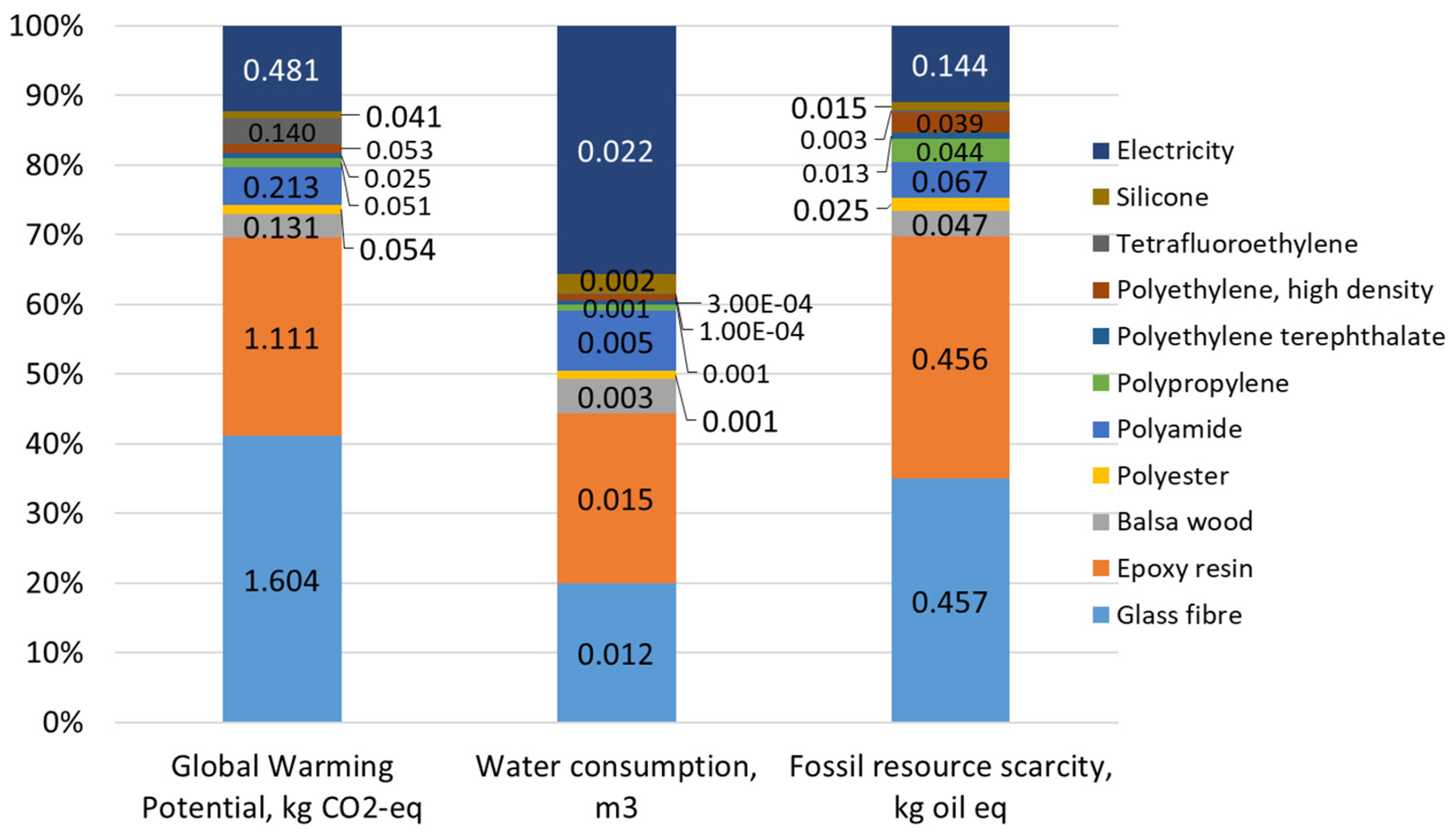
3.6. Vacuum Infusion Technology
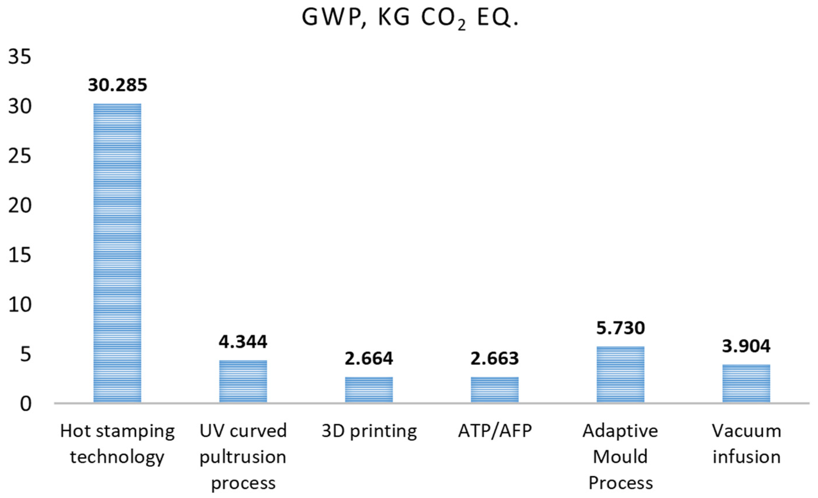
The analysis of GWP values for vacuum infusion technology showed that in total 3.9 kg CO2-eq. is emitted, where the highest percentages belong to glass fibre (41.1%) and epoxy resin (28.5%), Figure 9. The third highest impact on the carbon emissions belongs to electricity use—0.48 kg CO2-eq. (12.3%). The individual impact of other elements of the inventory does not exceed 5.5%, for example, for polyamide, tetrafluoroethylene, and balsa wood, and in many cases it is around 1% of total emissions, i.e., for polyester, polypropylene, high-density polyethylene, and silicone. Electricity use has the most significant share in the total water consumption (35.6%), since the generation of electricity is a water-intensive process.

4. Discussion

Figure 10 shows the comparison of the carbon footprint for particular technologies. Hot stamping technology shows the highest GWP index, since it is the only technology applying carbon fibre, which generates enormous amounts of CO2 during the production and raw material extraction stage. Three-dimensional printing and ATP/AFP show the lowest and comparable GWP index, which does not exceed 3 kg of CO2-eq., since those technologies use glass fibre and polypropylene as the main materials. Vacuum infusion showed an insignificantly higher GWP value of 3.9 kg of CO2-eq. and GWP for the adaptive mould process was estimated as 5.73 kg of CO2-eq.; both technologies, besides glass fibre, also use epoxy resin, which generates more CO2 emissions during the production stage compared to glass fibre and especially polypropylene. Cerdas et al. performed an LCA analysis of 3D-printed glass frames and reported a result for GWP in the range from about 0.3 to 0.6 kg CO2-eq generated during the production stage (cradle-to-gate boundaries) of one eye glass frame of a weight from ca. 14 to 19 g, which could be recalculated to a carbon footprint of about 21 to 38 kg CO2-eq [55]. These results give general information about similar research performed in the field, but could not be directly compared with our study because different methodologies, materials, function units, and scales were applied. For example, Cucinotta et al. carried out LCA of a yacht manufactured by vacuum infusion technology through the entire life cycle of the product (cradle-to-grave boundaries) [28]. Results of the study showed that about 96% of contribution to GWP belongs to the use phase, and the application of vacuum infusion technology compared to hand lay-up allows for reducing the weight of the yacht by 9%, which also reduces the carbon footprint due to lower material consumption during the manufacturing phase and lower fuel consumption during the usage phase.
In terms of water consumption, a similar tendency was observed; the analysed technologies may be sorted from the highest to the lowest water consumption: hot stamping technology—0.30 m3 per 1 kg of produced element, adaptive mould process—0.08 m3 per 1 kg, vacuum infusion process—0.06 m3 per 1 kg, UV curved pultrusion process—0.04 m3 per 1 kg, 3D printing and ATP/AFP—0.02 m3 per 1 kg (Figure 11).
As may be seen from Figure 12, the hot stamping technology is also the most energy-intensive process compared to other analysed technologies. As was discussed previously, if hot stamping technology is scaled up to the industrial level, then the amount of energy required to produce 1 kg of the item will be reduced, and there will be no need to preheat the press before manufacturing each item. The next technology with high energy consumption is the UV curved pultrusion process where 15.42 MJ/kg is used for four UV sources, robot arm, and gripper. The third technology with high energy consumption is vacuum infusion, which consumes 12.53 MJ/kg, which is needed mainly for the vacuum pump operation, fan heater, and oven used for post curing and the balsa wood curing process.
Since electricity use is a significant factor in water consumption and carbon emissions, it is worthwhile to mention that the implemented methodology and database take into consideration the application of renewable energy sources. In our analysis, we used “Country Energy Mix” to take into account electricity consumption for each technology according to the location of the partner. It means that if in Portugal the share of renewable energy in the total “Country Energy Mix” is higher than in other countries, it is already included in our calculations. Figure 13 shows per capita electricity generation from different sources: fossil fuel, nuclear sources, and renewables for countries, where partner facilities are located [56].
The main strength of our research is direct cooperation with technology providers in terms of data acquisition; therefore, in our LCA analysis, we considered technologies optimized from the point of view of mechanical performance of the produced elements, energy, and material consumption. The main limitation of our study, which does not take into account the longtime life span of ships built from composite materials, could be overcome by expanding the boundaries of the LCA analysis to include the usage phase, but in this case, the accuracy of calculations would be significantly reduced due to a large number of assumptions applied. To ensure accurate assessment of the entire life cycle of the product, technology transfer data, especially through its triple helix, should be taken into account to provide insights into the adoption and adaptation of manufacturing processes across different contexts [57,58]. It is recommended that approaches used in an LCA analysis should directly depend on stages of the market and technical maturity of analysed technology [59].

5. Conclusions

The total carbon footprint of analysed FRP technologies is mainly affected by the type of materials applied rather than by the amount of energy consumed during the process. Results of LCA calculations proved that the biggest environmental impact is produced by materials and compounds, from 80 to 95%. The typical materials applied in FRP technologies may be sorted from the highest to the lowest GWP impact as follows: carbon fibre, polyurethane foam, epoxy resin, glass fibre, polypropylene.
According to the ReCiPe Midpoint (H) methodology, three impact categories (terrestrial ecotoxicity, global warming, and human non-carcinogenic toxicity) are the most affected by the technologies developed in the frame of the project. The conclusions from the LCA calculations show that the environmental optimization of FRP production technologies must be based on the proper selection of materials and compounds.

Author Contributions

Conceptualization, A.Z.-S.; methodology, A.Z.-S.; software, A.Z.-S. and M.S.; validation, A.Z.-S. and I.Z.; formal analysis, A.Z.-S. and I.Z.; investigation, A.Z.-S.; resources, M.P. and M.S.; data curation, M.P. and M.S.; writing—A.Z.-S., M.S., and M.P.; writing—review and editing, A.Z.-S. and M.P.; visualization, M.P. and M.S.; supervision, I.Z.; project administration, I.Z.; funding acquisition, I.Z. All authors have read and agreed to the published version of the manuscript.

Funding

This project has received funding from the European Union’s Horizon 2020 research and innovation programme under grant agreement No 101006860.

Data Availability Statement

Data are contained within the article.

Conflicts of Interest

The authors declare no conflicts of interest.

References

  1. Lau, D. Hybrid Fiber-Reinforced Polymer (FRP) Composites for Structural Applications. In Developments in Fiber-Reinforced Polymer (FRP) Composites for Civil Engineering; Uddin, N., Ed.; Woodhead Publishing: Cambridge, UK, 2013; pp. 205–225. [Google Scholar]
  2. Rajak, D.K.; Pagar, D.D.; Menezes, P.L.; Linul, E. Fiber-Reinforced Polymer Composites: Manufacturing, Properties, and Applications. Polymers 2019, 11, 1667. [Google Scholar] [CrossRef]
  3. Abbood, I.S.; Odaa, S.A.; Hasan, K.F.; Jasim, M.A. Properties Evaluation of Fiber Reinforced Polymers and Their Constituent Materials Used in Structures—A Review. Mater. Today Proc. 2021, 43, 1003–1008. [Google Scholar] [CrossRef]
  4. Dolz, M.; Martinez, X.; Sá, D.; Silva, J.; Jurado, A. Composite materials, technologies and manufacturing: Current scenario of European Union shipyards. Ships Offshore Struct. 2023. [Google Scholar] [CrossRef]
  5. Kim, D.H.; Kim, H.G.; Kim, H.S. Design Optimization and Manufacture of Hybrid Glass/Carbon Fiber Reinforced Composite Bumper Beam for Automobile Vehicle. Compos Struct. 2015, 131, 742–752. [Google Scholar] [CrossRef]
  6. Yi, X.S. Development of multifunctional composites for aerospace application. In Multifunctionality of Polymer Composites; Friedrich, K., Breuer, U., Eds.; William Andrew Publishing: Oxford, UK, 2015; pp. 367–418. [Google Scholar]
  7. Chakraborty, B.C. FRP for Marine Application. In Fiber-Reinforced Plastics; Masuelli, M.A., Ed.; IntechOpen: Rijeka, Croatia, 2022; pp. 1–32. [Google Scholar]
  8. Luo, G.M.; Wu, C.W. Lightweight Fiber-Reinforced Plastic Constructions Using Improved Overlap Forms. Adv. Compos. Mater. 2015, 24, 545–560. [Google Scholar] [CrossRef]
  9. Vizentin, G.; Vukelic, G. Marine Environment Induced Failure of FRP Composites Used in Maritime Transport. Eng. Fail. Anal. 2022, 137, 106258. [Google Scholar] [CrossRef]
  10. Available online: https://www.fibre4yards.eu/ (accessed on 17 May 2023).
  11. Martinez, X.; Sá, D.; Silva, J.; Alvarez-Buylla, S. FIBRE4YARDS: Fibre Composite Manufacturing Technologies for the Automation and Modular Construction in Shipyards. Materiales Compuestos 2022, 6, 185. [Google Scholar] [CrossRef]
  12. Available online: http://www.inegi.pt/en/ (accessed on 3 March 2023).
  13. Karbasian, H.; Tekkaya, A.E. A Review on Hot Stamping. J. Mater. Process Technol. 2010, 210, 2103–2118. [Google Scholar] [CrossRef]
  14. Chen, J.; Li, X.; Han, X. Hot Stamping. Compr. Mater. Process. 2014, 5, 351–370. [Google Scholar]
  15. Available online: https://www.irurenagroup.com/ (accessed on 10 March 2023).
  16. Correia, J. Pultrusion of Advanced Fibre-Reinforced Polymer (FRP) Composites. In Advanced Fibre-Reinforced Polymer (FRP) Composites for Structural Applications; Bai, J., Ed.; Woodhead Publishing: Cambridge, UK, 2013; pp. 207–251. [Google Scholar]
  17. Qureshi, J. A Review of Fibre Reinforced Polymer Structures. Fibers 2022, 10, 27. [Google Scholar] [CrossRef]
  18. Tena, I.; Sarrionandia, M.; Torre, J.; Aurrekoetxea, J. The Effect of Process Parameters on Ultraviolet Cured out of Die Bent Pultrusion Process. Compos. Part B Eng. 2016, 89, 9–17. [Google Scholar] [CrossRef]
  19. Joshi, S.C. The Pultrusion Process for Polymer Matrix Composites. In Manufacturing Techniques for Polymer Matrix Composites (PMCs); Advani, S.G., Hsiao, K.T., Eds.; Woodhead Publishing: Cambridge, UK, 2012; pp. 381–413. [Google Scholar]
  20. Available online: https://10-xl.nl/ (accessed on 8 March 2023).
  21. Qureshi, Z.; Swait, T.; Scaife, R.; El-Dessouky, H.M. In Situ Consolidation of Thermoplastic Prepreg Tape Using Automated Tape Placement Technology: Potential and Possibilities. Compos. Part B Eng. 2014, 66, 255–267. [Google Scholar] [CrossRef]
  22. Yan, Q.; Dong, H.; Su, J.; Han, J.; Song, B.; Wei, Q.; Shi, Y. A Review of 3D Printing Technology for Medical Applications. Engineering 2018, 4, 729–742. [Google Scholar] [CrossRef]
  23. Ambrosi, A.; Pumera, M. 3D-Printing Technologies for Electrochemical Applications. Chem. Soc. Rev. 2016, 45, 2740–2755. [Google Scholar] [CrossRef]
  24. Shahrubudin, N.; Lee, T.C.; Ramlan, R. An Overview on 3D Printing Technology: Technological, Materials, and Applications. Procedia Manuf. 2019, 35, 1286–1296. [Google Scholar] [CrossRef]
  25. Jandyal, A.; Chaturvedi, I.; Wazir, I.; Raina, A.; Ul Haq, M.I. 3D Printing—A Review of Processes, Materials and Applications in Industry 4.0. Sustai. Oper Comput. 2022, 3, 33–42. [Google Scholar] [CrossRef]
  26. Available online: https://curveworks.nl/ (accessed on 27 April 2023).
  27. Kim, S.Y.; Shim, C.S.; Sturtevant, C.; Kim, D.; Song, H.C. Mechanical properties and production quality of hand-layup and vacuum infusion processed hybrid composite materials for GFRP marine structures. Int. J. Nav. Archit. Ocean Eng. 2014, 6, 723–736. [Google Scholar] [CrossRef]
  28. Cucinotta, F.; Guglielmino, E.; Sfravara, F. Life cycle assessment in yacht industry: A case study of comparison between hand lay-up and vacuum infusion. J. Clean Prod. 2017, 142, 3822–3833. [Google Scholar] [CrossRef]
  29. He, Y.; Xie, H.; Ge, Y.; Lin, Y.; Yao, Z.; Wang, B.; Jin, M.; Liu, J.; Chen, X.; Sun, Y. Laser Cutting Technologies and Corresponding Pollution Control Strategy. Processes 2022, 10, 732. [Google Scholar] [CrossRef]
  30. Mushtaq, R.T.; Wang, Y.; Rehman, M.; Khan, A.M.; Mia, M. State-Of-The-Art and Trends in CO2 Laser Cutting of Polymeric Materials—A Review. Materials 2020, 13, 3839. [Google Scholar] [CrossRef]
  31. Caiazzo, F.; Curcio, F.; Daurelio, G.; Minutolo, F.M.C. Laser cutting of different polymeric plastics (PE, PP and PC) by a CO2 laser beam. J. Mater. Process. Technol. 2005, 159, 279–285. [Google Scholar] [CrossRef]
  32. Der, O.; Başar, G.; Ordu, M. Statistical Investigation of the Effect of CO2 Laser Cutting Parameters on Kerf Width and Heat Affected Zone in Thermoplastic Materials. J. Mater. Mechatron. A 2023, 4, 459–474. [Google Scholar] [CrossRef]
  33. Agudelo, L.M.; Mejía-Gutiérrez, R.; Nadeau, J.P.; Pailhes, J. Life Cycle Analysis in Preliminary Design Stages. In Proceedings of the Joint Conference on Mechanical, Design Engineering & Advanced Manufacturing, Toulouse, France, 28 January–17 March 2014; pp. 1–7. [Google Scholar]
  34. Suhariyanto, T.T.; Wahab, D.A.; Rahman, M.N.A. Product Design Evaluation Using Life Cycle Assessment and Design for Assembly: A Case Study of a Water Leakage Alarm. Sustainability 2018, 10, 2821. [Google Scholar] [CrossRef]
  35. Mendoza Beltran, A.; Prado, V.; Font Vivanco, D.; Henriksson, P.J.G.; Guinée, J.B.; Heijungs, R. Quantified Uncertainties in Comparative Life Cycle Assessment: What Can Be Concluded? Environ. Sci. Technol. 2018, 52, 2152–2161. [Google Scholar] [CrossRef] [PubMed]
  36. Önal, M.; Neşer, G.; Gürsel, K.T. Environmental impacts of steel ship hulls building and recycling by life cycle assessment (LCA). Ships Offshore Struct. 2021, 16, 1061–1066. [Google Scholar] [CrossRef]
  37. Önal, M. Evaluation of shipyard operation processes with cradle-to-gate life cycle assessmentbased on material consumption rates for an aluminum and steel yacht. Ships Offshore Struct. 2023, 18, 1–7. [Google Scholar] [CrossRef]
  38. Tincelin, T.; Mermier, L.; Pierson, Y.; Pelerin, E.; Jouanne, G. A Life Cycle Approach to Shipbuilding and Ship Operation. In Proceedings of the Ship Design and Operation for Environmental Sustainability, London, UK, 10–11 March 2010. [Google Scholar]
  39. Oh, D.; Lee, D.K.; Jeong, S.H. Environmental Impact Evaluation on Lightweight Structure Design of a Composite Ship by LCA (Life Cycle Assessment). J. Korean Soc. Precis. Eng. 2019, 36, 875–881. [Google Scholar] [CrossRef]
  40. Burman, M.; Kuttenkeuler, J.; Stenius, I.; Garme, K.; Rosén, A. Comparative Life Cycle Assessment of the hull of a high-speed craft. Proc. Inst. Mech. Eng. Part M J. Eng. Marit. Environ. 2016, 230, 378–387. [Google Scholar] [CrossRef]
  41. ISO 14040:2006; Environmental Management—Life Cycle Assessment—Principles and Framework. ISO: Geneva, Switzerland, 2006.
  42. ISO 14044:2006; Environmental Management—Life Cycle Assessment—Requirements and Guidelines. ISO: Geneva, Switzerland, 2006.
  43. Jiménez-González, C.; Kim, S.; Overcash, M.R. Methodology for developing gate-to-gate Life cycle inventory information. Int. J. Life Cycle Assess. 2000, 5, 153–159. [Google Scholar] [CrossRef]
  44. Zhou, H. The Comparative Life Cycle Assessment of Structural Retrofit Technique; SSEBE-CESEM-2013-CPR-009; Arizona State University: Tempe, AZ, USA, 2013. [Google Scholar]
  45. Meng, F.; Mckechnie, J.; Turner, T.A.; Pickering, S.J. Energy and environmental assessment and reuse of fluidised bed recycled carbon fibres. Compos. Part A Appl. Sci. Manuf. 2017, 100, 206–214. [Google Scholar] [CrossRef]
  46. Wu, M.; Sadhukhan, J.; Murphy, R.; Ujjwal Bharadwaj, U.; Cui, X. A novel life cycle assessment and life cycle costing framework for carbon fibre-reinforced composite materials in the aviation industry. Int. J. Life Cycle Assess. 2023, 28, 566–589. [Google Scholar] [CrossRef]
  47. Karuppannan Gopalraj, S.; Deviatkin, I.; Horttanainen, M.; Kärki, T. Life Cycle Assessment of a Thermal Recycling Process as an Alternative to Existing CFRP and GFRP Composite Wastes Management Options. Polymers 2021, 13, 4430. [Google Scholar] [CrossRef]
  48. Das, S. Life cycle assessment of carbon fiber-reinforced polymer composites. Int. J. Life Cycle Assess. 2011, 16, 268–282. [Google Scholar] [CrossRef]
  49. Isa, A.; Nosbi, N.; Che Ismail, M.; Md Akil, H.; Wan Ali, W.F.F.; Omar, M.F. A Review on Recycling of Carbon Fibres: Methods to Reinforce and Expected Fibre Composite Degradations. Materials 2022, 15, 4991. [Google Scholar] [CrossRef] [PubMed]
  50. Hermansson, F.; Svanström, M.; Janssen, M. (Eds.) HORIZON 2020, BBI.VC1.R1-2015-2-1/720707/, Project 720707: Lignin Based Carbon Fibres for Composites, D8.1 Recommendations for Optimal Routes to Sustainable Exploitation of LIBRE Materials and Processes from Completed Life Cycle Analysis; Chalmers University of Technology: Gothenburg, Sweden, 2017. [Google Scholar]
  51. Tchana Toffe, G.; Oluwarotimi Ismail, S.; Montalvão, D.; Knight, J.; Ren, G. A Scale-up of Energy-Cycle Analysis on Processing Non-Woven Flax/PLA Tape and Triaxial Glass Fibre Fabric for Composites. J. Manuf. Mater. Process. 2019, 3, 92. [Google Scholar] [CrossRef]
  52. Stiller, H. Material Intensity of Advanced Composite Materials: Results of Asudy for the Verbundwerkstofflabor Bremen Ev; Wuppertal Papers; EconStor: Kiel, Germany, 1999. [Google Scholar]
  53. Korol, J.; Hejna, A.; Burchart-Korol, D.; Chmielnicki, B.; Wypiór, K. Water Footprint Assessment of Selected Polymers, Polymer Blends, Composites, and Biocomposites for Industrial Application. Polymers 2019, 11, 1791. [Google Scholar] [CrossRef]
  54. CO2-Footprint of Getzner Werkstoffe GmbH PU Products; Getzner Werkstoffe GmbH: Bürs, Austria, 2019; Available online: https://www.mecanocaucho.com/download/catalog/Sylomer_Environmental_Product_Declaration.pdf (accessed on 14 October 2023).
  55. Cerdas, F.; Juraschek, M.; Thiede, S.; Herrmann, C. Life Cycle Assessment of 3D Printed Products in a Distributed Manufacturing System. J. Ind. Ecol. 2017, 21 (Suppl. S1), S80–S93. [Google Scholar] [CrossRef]
  56. Available online: https://ourworldindata.org/electricity-mix (accessed on 13 February 2024).
  57. Craiut, L.; Bungau, C.; Bungau, T.; Grava, C.; Otrisal, P.; Radu, A.-F. Technology Transfer, Sustainability, and Development, Worldwide and in Romania. Sustainability 2022, 14, 15728. [Google Scholar] [CrossRef]
  58. Craiut, L.; Bungau, C.; Negru, P.A.; Bungau, T.; Radu, A.-F. Technology Transfer in the Context of Sustainable Development—A Bibliometric Analysis of Publications in the Field. Sustainability 2022, 14, 11973. [Google Scholar] [CrossRef]
  59. Bergerson, J.A.; Brandt, A.; Cresko, J.; Carbajales-Dale, M.; MacLean, H.L.; Matthews, H.S.; McCoy, S.; McManus, M.; Miller, S.A.; Morrow, W.R.; et al. Life cycle assessment of emerging technologies. Eval. Tech. Differ. Stages Mark. Tech. Matur. 2020, 24, 11–25. [Google Scholar]
Figure 1. Schematic illustration of the final demonstrator in Fibre4Yards project.
Processes 12 00461 g001
Figure 2. Life cycle assessment (LCA) stages according to ISO 14044.
Processes 12 00461 g002
Figure 3. Different system boundaries for LCA.
Processes 12 00461 g003
Figure 4. Environmental impact of production of 1 kg of brackets applying hot stamping technology. Note: Global Warming Potential—according to IPCC 2021 GWP 100a methodology; water consumption and fossil resource scarcity—according to ReCiPe 2016 Midpoint (H) V1.06/World (2010) H.
Processes 12 00461 g004
Figure 5. Environmental impact of production of 1 kg of stiffeners for superstructure panels applying UV curved pultrusion process. Note: Global Warming Potential—according to IPCC 2021 GWP 100a methodology; water consumption and fossil resource scarcity—according to ReCiPe 2016 Midpoint (H) V1.06/World (2010) H.
Processes 12 00461 g005
Figure 6. Environmental impact of production of 1 kg of pillars applying ATP/AFP process. Note: Global Warming Potential—according to IPCC 2021 GWP 100a methodology; water consumption and fossil resource scarcity—according to ReCiPe 2016 Midpoint (H) V1.06/World (2010) H.
Processes 12 00461 g006
Figure 7. Environmental impact of production of 1 kg of pillars applying 3D printing. Note: Global Warming Potential—according to IPCC 2021 GWP 100a methodology; water consumption and fossil resource scarcity—according to ReCiPe 2016 Midpoint (H) V1.06/World (2010) H.
Processes 12 00461 g007
Figure 8. Environmental impact of production of 1 kg of superstructure panels applying adaptive mould process. Note: Global Warming Potential—according to IPCC 2021 GWP 100a methodology; water consumption and fossil resource scarcity—according to ReCiPe 2016 Midpoint (H) V1.06/World (2010) H.
Processes 12 00461 g008
Figure 9. Environmental impact of production of 1 kg of deck panel applying vacuum infusion technology. Note: Global Warming Potential—according to IPCC 2021 GWP 100a methodology; water consumption and fossil resource scarcity—according to ReCiPe 2016 Midpoint (H) V1.06/World (2010) H.
Processes 12 00461 g009
Figure 10. GWP of analysed fibre-reinforced polymer (FRP) technologies per kg of produced element (according to IPCC 2021 GWP 100a methodology).
Processes 12 00461 g010
Figure 11. Water consumption of analysed FRP technologies per kg of produced element (according to ReCiPe 2016 Midpoint (H) V1.06/World (2010) H).
Processes 12 00461 g011
Figure 12. Energy consumption of analysed FRP technologies per kg of produced element (based on data provided by project partners).
Processes 12 00461 g012
Figure 13. Per capita electricity generation from fossil fuels, nuclear sources, and renewables, 2022, for partner locations [56].
Processes 12 00461 g013
Table 1. Advantages and disadvantages of particular technologies applied in F4Y project.
TechnologyAdvantagesDisadvantages
Hot stamping▪ it can be used to process a wide range of materials (plastics, rubbers, metals, wood, leather, glass);
▪ clean production environment.
▪ part size;
▪ slow cooling rates;
▪ heat vs. thickness vs. material ratio.
Ultraviolet (UV) curved pultrusion process (Robtrusion®)▪ suitable for mass production;
▪ low raw material cost;
▪ highly automatable process;
▪ high process stability and output.
▪ limited to the production of products with single cross-sectional shape;
▪ limited to transparent materials regarding UV radiation;
▪ part size regarding width and height depends on the dimensions of the UV sources, the pulling force capacity of the robot arm, and the gripper dimensions;
▪ limited to constant cross-section profiles.
Automated tape (fibre) placement▪ increased productivity;
▪ superior accuracy and precision;
▪ high volume capability;
▪ capability to produce complex geometries;
▪ low amount of material waste.
▪ limitation on acceptable mould shapes.
Three-dimensional (3D) printing ▪ ability to produce very complex shapes or geometries;
▪ rapid prototyping;
▪ fast production;
▪ minimising waste;
▪ cost-effective.
▪ the dimensions of the part depend on the robot scale;
▪ in some cases, parts need post processing.
Adaptive mould▪ reduce waste;
▪ suited to process a broad range of composite materials.
▪ curvature of the part is limited by the curvature of the adaptive mould.
Table 2. Inventory for Hot Stamping Technology.
StageComponentEcoinvent DatabaseUnit
Materials and CompoundsPolypropylenePolypropylene, granulate (global market)[kg]
Carbon fibreCalculated based on Wu et al. [46]. Carbon fibre production (per 1 kg):
Polyacrylonitrile fibres—1.69 kg
Nitrogen—11.49 kg
Electricity—250 MJ/kg
Heat—190 MJ/kg
Mould cleaner agent solventOrganic solvent (global market)[g]
Release agent: solvent-based
polymer
Toluene liquid (European market), methyl ethyl ketone (European market)[g]
Clamping plate
(aluminium)
Aluminium alloy (global market)[g]
EnergySpot weldingElectricity medium voltage (Portugal)[Wh]
Hot plate press
pump
Electricity medium voltage (Portugal)[Wh]
Hot plate press
heater
Electricity medium voltage (Portugal)[Wh]
Press auxiliary
cooling system
Electricity medium voltage (Portugal)[Wh]
Blank holder systemElectricity medium voltage (Portugal)[Wh]
Infrared ovenElectricity medium voltage (Portugal)[Wh]
PressElectricity medium voltage (Portugal)[Wh]
Table 3. Inventory for ultraviolet (UV) Curved Pultrusion process.
StageComponentEcoinvent DatabaseUnit
Materials and CompoundsUD glass fibreGlass fibre (global market)[kg]
QD glass fibre[kg]
UV formulation
(acrylate)
Polyester resin (global market)[kg]
AcetoneAcetone liquid (European market)[kg]
Paper for cleaningTissue paper (global market)[kg]
EnergyUV sources type 1
(two sources)
Electricity medium voltage (Spain)[MJ]
UV sources type 2
(two sources)
Electricity medium voltage (Spain)[MJ]
UV sources type 3
(two sources)
Electricity medium voltage (Spain)
UV sources type 4
(two sources)
Electricity medium voltage (Spain)
Robot armElectricity medium voltage (Spain)[MJ]
GripperElectricity medium voltage (Spain)[MJ]
Table 4. Inventory for ATP/AFP technology.
StageComponentEcoinvent DatabaseUnit
Materials and CompoundsPolypropylenePolypropylene (global market)[kg]
Glass fibreGlass fibre (global market)[kg]
Oxygen, 4 barOxygen, liquid (European market)[L]
Hydrogen, 4 barHydrogen, liquid (European market)[L]
EnergyATP/AFP—machine electricity consumptionElectricity medium voltage (the Netherlands)[MJ]
Table 5. Inventory for 3D printing.
StageComponentEcoinvent DatabaseUnit
Materials and CompoundsPolypropylenePolypropylene (global market)[kg]
Glass fibre (30%)Glass fibre (global market)[kg]
UV stabilizer (0.2%) (acetic acid trade mix–organic compound)Acetic acid (global market)[kg]
UV absorber
(0.1%) (phenol)
Phenol (non-European market)[kg]
Anti-microbial (3%)
(PP random copolymer)
Polypropylene (global market)[kg]
Flame retardant (tris (1-chloro 2-propyl) phosphate (TCPP))Tris (global market)[kg]
Coupling agent
(3%) (MAPP)
Maleic anhydride (global market)[kg]
Anti-oxidants
(organic phosphite) (0.1%)
Phosphoric acid (global market)[kg]
Heat stabilizer (0.1%)Phenolic resin (European market)[kg]
Energy3D printing—heating
up + standby
Electricity medium voltage (the Netherlands)[MJ]
3D printing—extrudingElectricity medium voltage (the Netherlands)[MJ]
3D printing—robotic armElectricity medium voltage (the Netherlands)[MJ]
3D printing—heatingElectricity medium voltage (the Netherlands)[MJ]
Table 6. Inventory for adaptive mould process.
StageComponentEcoinvent DatabaseUnit
Materials and CompoundsGlass fibreGlass fibre (global market)[kg]
EpoxyEpoxy resin (non-European market)[kg]
Structural foam corePolyurethane, rigid foam (non-European market)[kg]
EnergyHeating foam coreElectricity medium voltage (the Netherlands)[kWh]
Shaping foam coreElectricity medium voltage (the Netherlands)[kWh]
Cutting foam coreElectricity medium voltage (the Netherlands)[kWh]
Shaping mould for
infusion and curing
Electricity medium voltage (the Netherlands)[kWh]
Heating/curingElectricity medium voltage (the Netherlands)[kWh]
Table 7. Inventory for vacuum infusion process.
StageComponentEcoinvent DatabaseUnit
Materials and CompoundsGlass fibreGlass fibre (global market)[kg]
Epoxy resin for infusionEpoxy resin, liquid (non-European market)[kg]
Balsa woodJoist, engineered wood (global market)[m]
Polyester adhesiveFibre, polyester (global market)[kg]
Epoxy resin for balsaEpoxy resin, liquid (non-European market)[kg]
BreatherPolyethylene terephthalate, granulate, amorphous (global market)[kg]
Peel plyGlass-fibre-reinforced plastic,
polyamide, injection-moulded (European market)
[kg]
MembranePolypropylene, granulate (European market)[kg]
Extruded netPolypropylene, granulate (European market)[kg]
Plastic film (fibre protector)Glass-fibre-reinforced plastic, polyamide, injection-moulded (European market)[kg]
Plastic film (PO120)Polyethylene, high density, granulate (European market)[kg]
Plastic film (PO175)Polyethylene, high density, granulate (European market)[kg]
BucketPolypropylene, granulate (European market)[kg]
Plastic tubePolyethylene, high density, granulate (global market)[kg]
Silicone tubeSilicone product (European market)[kg]
Knitted net complexPolyethylene terephthalate, granulate, amorphous (global market)[kg]
Plastic “T”Polypropylene, granulate (European market)[kg]
SealantSilicone product (European market)[kg]
Teflon filmTetrafluoroethylene (global market)[kg]
Supply railPolyethylene terephthalate, granulate, amorphous (global market)[kg]
Plastic studPolyethylene, high density, granulate (global market)[kg]
EnergyDrillElectricity medium voltage (France)[MJ]
Circular sawElectricity medium voltage (France)[MJ]
Table sawElectricity medium voltage (France)[MJ]
Sabre sawElectricity medium voltage (France)[MJ]
Vacuum pumpElectricity medium voltage (France)[MJ]
OvenElectricity medium voltage (France)[MJ]
Fan heaterElectricity medium voltage (France)[MJ]
Disclaimer/Publisher’s Note: The statements, opinions and data contained in all publications are solely those of the individual author(s) and contributor(s) and not of MDPI and/or the editor(s). MDPI and/or the editor(s) disclaim responsibility for any injury to people or property resulting from any ideas, methods, instructions or products referred to in the content.

