

Design and Sensitivity Analysis of Mechanically Actuated Digital Radial Piston Pumps


1
Engineering Technology, School of Engineering Technology, Purdue University, West Lafayette, IN 47906, USA
2
Agricultural and Biological Engineering, Purdue University, West Lafayette, IN 47906, USA
3
Computer and Information Technology, School of Engineering Technology, Purdue University, West Lafayette, IN 47906, USA
*
Author to whom correspondence should be addressed.
Processes 2024, 12(3), 504; https://doi.org/10.3390/pr12030504
Submission received: 10 January 2024
/
Revised: 1 February 2024
/
Accepted: 23 February 2024
/
Published: 29 February 2024
(This article belongs to the Special Issue Design and Optimization Method of Pumps)
Abstract
:One major challenge in fluid power is the improvement and optimization of the efficiency of mobile hydraulic systems. Conventional fluid power systems often exhibit relatively low overall efficiencies caused by inefficiencies in the various components, such as a prime mover, variable displacement pump, valves, fittings, hoses, and actuators. While each component contributes to the losses in the overall system, the pump converts the mechanical shaft energy from the prime mover to energy transmitted hydraulically and is one of the most crucial components impacting overall system efficiency. Using on/off technologies, new pump architectures have enabled the opportunity to increase the efficiency over conventional designs using positive sealing valves in place of conventional port plate designs. This work proposes, investigates, and assesses the development and optimization of a digital variable displacement pump using a novel cam actuation technique on radial piston pumps. The novelty of this work is the development and parameter optimization of a mechanically actuated digital radial piston pump that can achieve high efficiencies from minimum to maximum displacement compared to common conventional variable displacement pump technologies. In this study, a sensitivity analysis is conducted to study the parameters of the system to optimize the pump. The parameters assessed in this study include: the valve bore size, cam transition and compression angles, piston diameter, and dead volume in the pumping chamber. The simulation results show that after optimizing the parameters of the system, the pump in design could reach a maximum efficiency of approximately 93% and was capable of upholding efficiencies above 80% between 30–100% displacement.
1. Introduction
Greenhouse gas emissions and energy consumption are growing concerns in applications that rely on internal combustion engines as their primary source of input energy, such as machines and vehicles commonly found in construction, mining, agriculture, transportation, etc. The emissions created by these machines significantly contribute to air pollution and global warming [1]. Thus, regulations set by the United States Environmental Protection Agency (EPA) continue to mandate further reductions in the emissions of these machines and vehicles. The future goal is to achieve a net zero-emission economy by 2050 [2,3]. A study conducted by the EPA [4] showed that transportation and agriculture contributed over 33% of the emissions in the United States. Currently, for the offroad sector, manufacturers must produce machines that fall within Tier 4 emission standards in the United States, which reduce harmful emissions by up to 90% compared to previously mandated Tier 3 emissions [5].
Conventional heavy equipment machines commonly used in offroad industries utilize internal combustion engines and hydraulics as the main source of energy transfer for operating heavy earth-moving tools and implements. While hydraulic machines have great power-to-weight ratios, conventional systems are known for being relatively inefficient [6,7]. A study conducted by the United States Department of Energy showed that the average efficiency for mobile hydraulic systems is around 21% [8]. The relatively low efficiency contributes to the hydraulic system by having several key components, including the pump, valves, hoses, fittings, and actuators; each of which have their own particular losses in the system [9]. Thus, there are many areas of opportunity for improving the efficiency and optimizing the overall performance of these systems as modern technologies are developed [10]. The hydraulic pump, one of the major components of fluid power systems, is responsible for transferring mechanical energy from the shaft to fluid flow, which is used to create hydraulic power.
Two categories of pumps are used in fluid power systems, fixed and variable displacement. The type of pump is chosen based on the system’s operating requirements and design goals. Fixed displacement pumps provide a geometrically fixed volume of fluid displaced per rotation of the pump’s shaft. Therefore, flow can only be varied by changing the pump’s speed. Variable displacement pumps can adjust the amount of volume displaced in each shaft revolution, thereby varying the flow without necessarily changing the pump’s input speed. This allows the pump’s flow rate to change to meet the system’s requirements [11]. Variable displacement pumps are commonly used in mobile hydraulic systems with internal combustion engines to keep the prime mover at optimal operating conditions. Axial piston, bent axis, and variable vane pumps are among the most common commercially available variable displacement pumps used in these systems.
The design of the most commonly used variable displacement pumps In heavy equipment machines, axial piston pumps, uses axially aligned pistons actuated by a variable angled plate, known as a swashplate. The angle of the plate dictates the stroke of each piston, changing the displacement of the pump [12]. However, the design of this plate makes it prone to volumetric losses due to leakages across the valve plate [13]. A system architecture that eliminates these leakage paths and achieves improved peak volumetric efficiencies is fixed displacement piston pumps. These fixed displacement inline piston pumps and radial piston pumps use pressure-actuated, spring-return check valves on the inlet and outlet ports which positively seal, eliminating the leakages seen across the valve plate. However, the actuation technique of these valves limits their capabilities of achieving variable displacements. Obtaining synergy between these two systems could enable a variable displacement pump capable of achieving higher overall efficiencies than common variable displacement pumps.
In this work, a variable displacement pump is designed and simulated using a fixed displacement piston pump architecture and a new cam actuation system for controlling the inlet and outlet valves of the pump, creating what is hereby known as a mechanically actuated digital pump. The novelty in this work is the sensitivity analysis used in developing this system, which was used to optimize the parameters of the pump. This provides insight into the potential efficiencies a mechanically actuated digital pump could reach if a design were to be developed with the intent of commercialization.
2. Background
This section discusses the background and development of digital hydraulic pumps that led to the conceptualization and development of a mechanically actuated digital radial piston pump.
2.1. Digital Hydraulic Technologies
Digital hydraulics, in general, describe the use of on/off, two-state valves to control fluid power systems. In terms of hydraulic pumps/motors, digital pumps/motors describe the use of actively controlled on/off valves to control fluid in and out of the displacement chamber enabling variable displacement pumping or motoring. This allows the pump to achieve various non-conventional pumping and motoring operations referred to as digital hydraulic flow strategies. The active control of the on/off valves can be achieved electrically or mechanically.
The flow strategies enabled by the active control of digital hydraulic pumps are partial/sequential flow diverting and partial/sequential flow limiting. In flow-diverting strategies, full flow is taken in during the inlet stroke and diverted back through the inlet port during the outlet stroke. This is achieved by leaving the inlet valve open and the outlet valve closed during the outlet stroke. During this phase, the fluid in the chamber can either be partially diverted (partial flow diverting) or fully diverted (sequential flow diverting). The difference between the amount of fluid taken in during the inlet stroke and the flow diverted out of the system during the outlet phase determines the amount of fluid displaced by the machine. In flow-limiting strategies, fluid is restricted from entering the chamber during the inlet stroke, by leaving the inlet valve either fully closed (sequential flow limiting) or only closing the valve for part of the stroke (partial flow limiting).
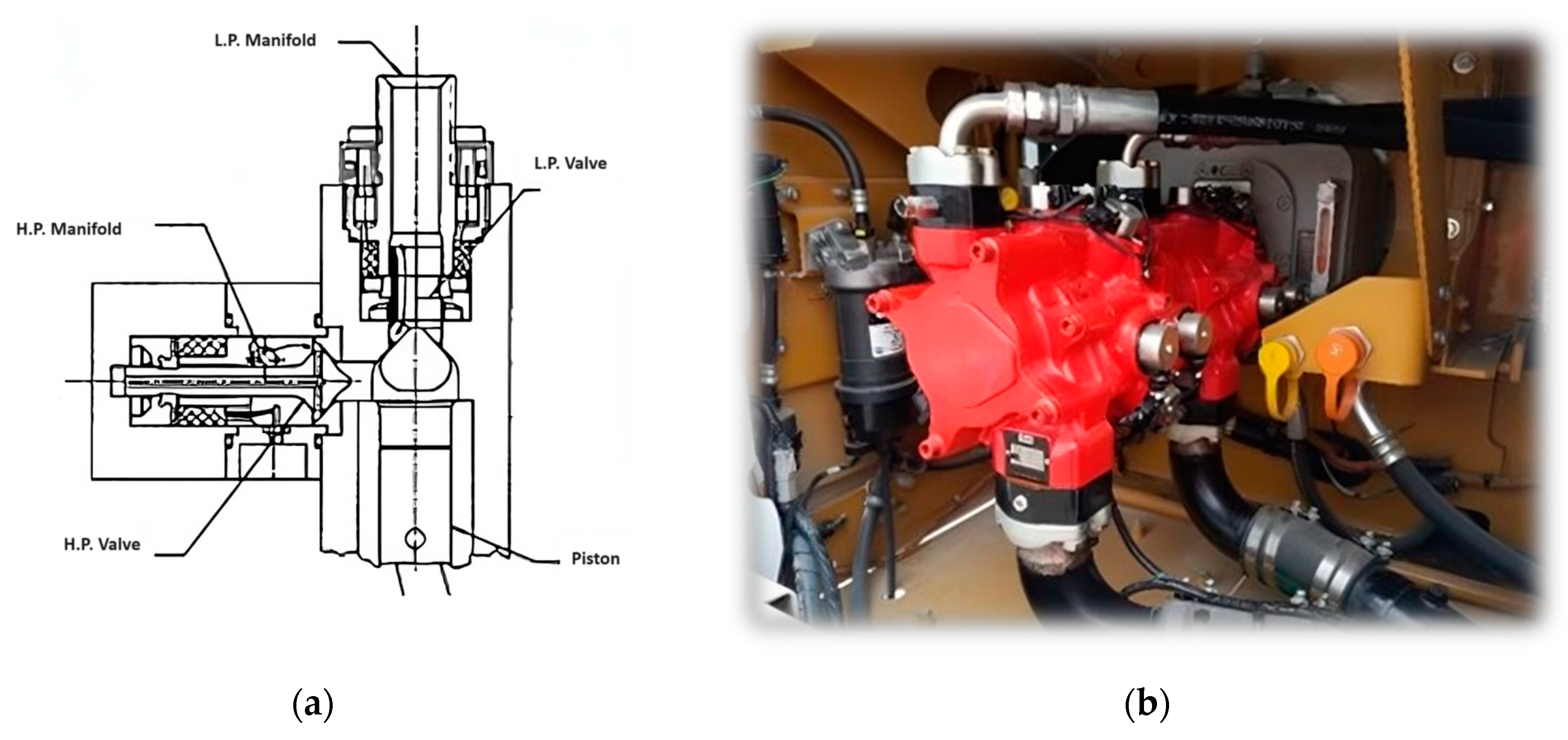
The state-of-the-art digital-displacement pumps in research are developed with poppet valves that use electromagnetic solenoids, shown in Figure 1a. These valves are controlled using microprocessors and the feedback from sensors, in place of conventional self-acting hydraulic check valves used on common fixed displacement pumps. This added control over the system enables the pumps to achieve variable displacements by latching the inlet valve open during the discharge stroke, disabling the output of specified cylinders (sequential flow diverting). The decision to enable or disable cylinders is processed by the microcontroller and controls, based on flow demand. These digital-displacement pump/motors have the benefits of increased response control and energy efficiency, as demonstrated by Artemis Intelligent Power Ltd. [14]. A modern configuration of the Artemis Technology on a Danfoss Digital Displacement pump; after Danfoss acquired Artemis Intelligent Power [15], is shown below in Figure 1b. Danfoss has continued the development of these systems, recently working on creating systems that can enable both pumping and motoring strategies [16].
Another option in digital pumps is replacing the hydraulically actuated check valves with actively controlled on/off electrically actuated valves, as shown in Figure 2a. This enables the pump to achieve all four digital pump operating strategies previously discussed. These operating strategies have been extensively detailed in prior research [17]. An electrically actuated valving system was developed at Purdue University to analyze and understand the benefits and limitations of each of these strategies. Figure 2b shows the experimental test bench that was used in the investigation of electrically actuated valving systems for digital pumps [18].
2.2. Mechanical Actuation Techniques
While an electrical system provides many degrees of freedom, such as programming different opening and closing profiles, it also requires expensive sensors, data acquisition systems, complex controls, and additional power for actuating the valves. Since on/off valves can be actuated electrically or mechanically, various mechanically actuated digital pump designs have been conceptualized to focus on addressing these limitations [19]. Due to limited magnetic force in electromagnetic actuators, the dynamic response of the valve may be limited. Repeatability with electrical actuators are also potential problems, as research at Purdue University demonstrated that variance in valve response times negatively impacts the overall efficiency. Various works have focused on mitigating these delays using peak-and-hold and reverse currents strategies and data-driven modeling for real time valve delay estimation [20,21]. To reduce the losses caused by variations in valve responses and the need for electrical power and sensors, a mechanically actuated digital inline pump was designed to control the on/off valve actuation and enable the partial flow diverting digital pump operating strategy. The proposed method results in a mechanical actuation method that achieves consistent and reliable valve timing, mitigating the delays and associated losses in the system. The system also eliminates the limitations of electrically actuated systems: data acquisition systems, complex controls, and added energy sources. Figure 3 demonstrates the mechanically actuated valve system developed and tested at Purdue University, which illustrates (a) the mechanically actuated cams, known as half-masking cams, and (b) the mechanism used to change displacement in real-time on the mechanically actuated digital inline piston pump [22].
The digital pump shown in Figure 4b was developed and tested at Purdue to evaluate the performance and feasibility of a mechanically actuated valve system for digital pumps. The results showed that the mechanically actuated digital pump’s energy efficiency outperformed the electrically actuated digital pump (using on/off solenoid valves) by up to 10% at 50% displacement, shown in Figure 4a. This operating condition (50% displacement), corresponds to the moment when the pumping element is halfway through the outlet stroke and the inlet valve is transitioning from open to closed, using the partial flow diverting strategy. At this moment, the piston is at its highest instantaneous velocity, outputting the pumps peak instantaneous volumetric flow rate. Thus, at this condition, valve timing and valve losses are most critical. Only the actuation method differed between the two tests and identical valves were used. This valve actuation strategy used by the mechanically actuated pump has been detailed in recent research [23]. Since the Mechanically Actuation Valving (MAV) system is capable of much larger actuation forces compared to solenoids, additional efficiency gains at the other operating points would be realized by incorporating larger valves. One disadvantage of the inline pump configuration is that it requires a separate cam actuator for each valve, resulting in the increased system size and inconvenient geometry compared to electrically actuated systems.
To reduce the number of masking cams and simplify the configuration, a mechanical actuation system can also be applied to other reciprocating piston-pump configurations, such as radial piston pumps. This enables the opportunity to downsize the pump while still maintaining the benefits seen on inline piston pumps. This is achieved by having all the inlet on/off valves controlled by a single half-masking cam (another cam could be used for the outlet valves). The on/off valve for each cylinder can be radially aligned around the cams, either in the center of the pump or on the outside of the pump, depending on the orientation of the valves. Thus, by radially aligning the valves on the various pumping elements, the number of cam sets can be reduced to a single set of cams, enabling digital control in pumping operations. Adding an additional set of cams on the outlet valves creates the opportunity to achieve pumping and motoring strategies. Additionally, integrating these cams within the pump helps with lubrication to reduce wear and friction losses caused by the cams.
Compared to the state-of-the-art electronic latching and on/off valve technologies, mechanically actuated valving systems offer a simpler and more robust solution for achieving variable displacements in digital hydraulic pump technologies. This is due to the elimination of data acquisition systems, adding energy sources for actuating the valves, and solenoid valves, which can have latency in valve response. While these technologies promote a more robust valve actuation technique, the drawbacks of current systems are added friction and their limitations in achieving sequential flow-diverting and flow-limiting strategies that have the potential to reach higher efficiencies. The benefits and limitations are listed in Table 1, below.
3. Pump Design and Simulation
This section discusses the conceptualization, design, operating strategies, and simulation in the development of a digital radial piston pump utilizing a mechanically actuated valving system. The system is simulated in the pumping operation with a clockwise shaft rotation. The simulation model presented in this paper was used to evaluate the potential efficiencies of a mechanically actuated digital radial piston pump could achieve if a commercializable design was created.
3.1. Conceptual Design
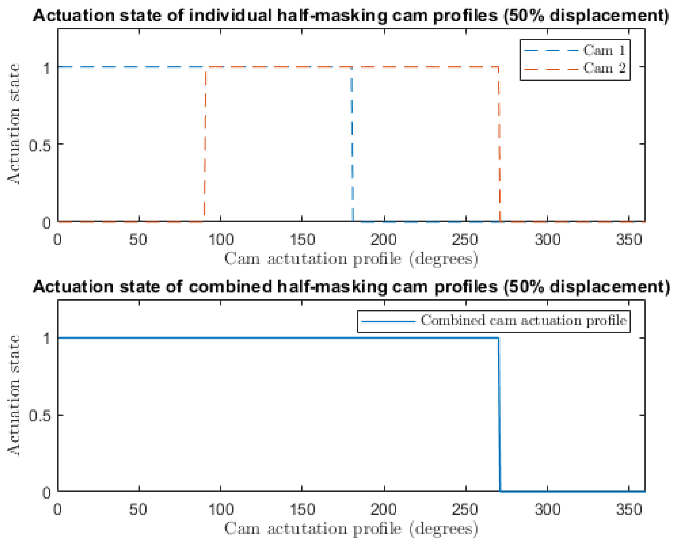
A mechanically actuated valve system was conceptualized to create a compact digital piston pump with a manufacturable design that could reach high efficiencies throughout the range of its displacement. This hydraulic configuration of the mechanically actuated digital pump uses a dual set of mechanically actuated valves and cams on the inlet and outlet ports of the pump. The mechanically actuated on/off valves on the pump are opened via a variable geometry half-masking cam like the ones shown in Figure 3a. The valve is mechanically actuated using the cam profile and closed using a spring. The cam profiles are phased together to achieve a variable state that enables the valve to be opened or closed for an extended period. An example of the variable state profile for the pump operating at 50% displacement is shown in Figure 5. The dashed blue line shows the actuation state of the valve imposed by the first half-masking cam for the entirety of the inlet stroke, while the dashed orange line shows the second (phased) half masking cam, which is used to extend the duration that the valve is in an open state during the outlet stroke, enabling the pump to achieve the partial flow diverting strategy. The solid blue line shows the actual state of the valve when these profiles of the cams are combined.
This allows the pump to be controlled with a simple mechanical actuation, eliminating the requirement of added energy sources for actuating the valves, complex controls, or data acquisition systems. Although the cam actuator must open the valves by overcoming the spring force, the majority of this energy is returned when the valve closes, similar to cam-driven valve trains in internal combustion engines.
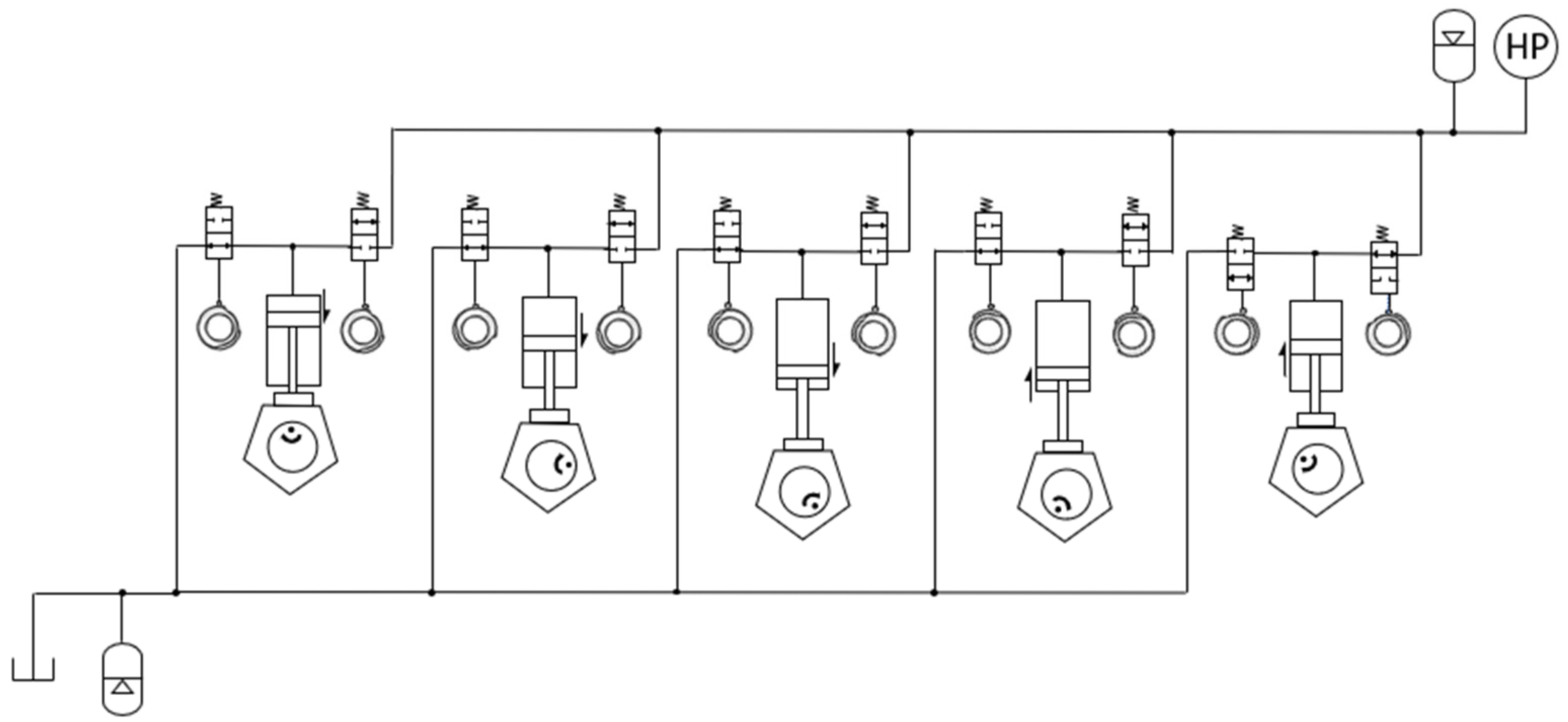
The conceptual pump model includes an eccentric cam used for the pump driver and dual mechanically actuated cam sets on the inlet and outlet valves. The eccentric cam actuates a hexagonal feature that produces linear motion to the reciprocating pistons. The dual mechanically actuated cam sets actuate the inlet and outlet valves. The mechanically actuated cams enable the pump to utilize the digital hydraulic flow strategies previously discussed in the background. The pump’s hydraulic configuration that is simulated is shown in Figure 6. Arrows are used to indicate the direction of motion of each piston in the diagram.
3.2. Flow Diverting Operating Strategy
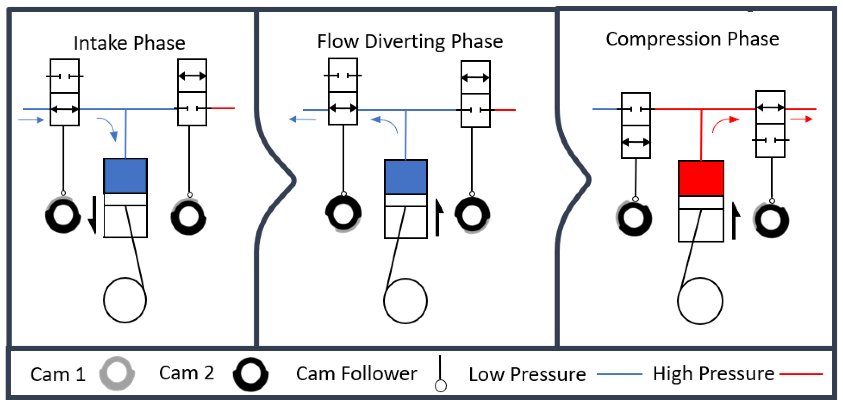
To control the pump’s displacement, each set of half-masking cams is set to the same geometry and phased in sync with one another. One-half masking cam set is used to control the inlet valves, while the other set is used to control the outlet valves. During the suction phase, the inlet valve is opened mechanically via the half-masking cam set, and the outlet valve is closed. The inlet stroke creates a pressure differential that enables fluid to freely enter the chamber. As the piston overcomes its bottom-dead-center position, the flow-diverting phase begins. In this phase, the inlet valve is left open for a partial stroke while the outlet valve stays closed. This causes the pressure in the pumping chamber to increase and force fluid back through the inlet valve, diverting the flow back into the low-pressure side. When the desired amount of fluid to be displaced is achieved, the inlet valve closes, and the outlet valve is opened, displacing the fluid left in the chamber to the high-pressure side. A further illustration of how partial flow-diverting techniques can be achieved using the configuration is shown in Figure 7. Arrows are used to indicate the direction of motion of each piston in the diagram.
3.3. Cam Phasing and Pump Development
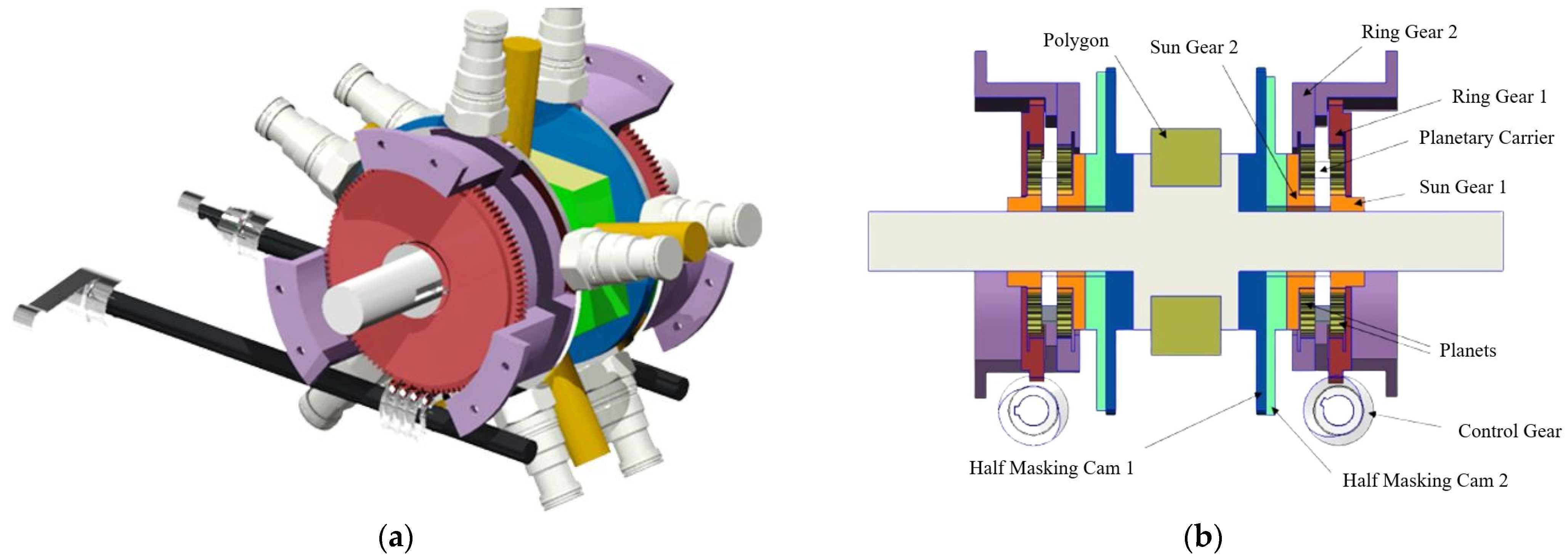
A mechanism was designed to phase the cams in real-time using concepts similar to the inline pump previously developed at Purdue University, shown in Figure 3b. This design includes various planetary gear sets used to phase each cam set; the mechanism housing the cams is shown in Figure 8a below. The breakdown of the components used to phase the cams is shown in Figure 8b. The pump shaft houses a sun gear attached via a key on the pump’s input shaft, referred to as Sun Gear 1 in the figure. The sun gear drives planetary gears against the outer ring gears depicted as Ring Gear 1 and 2. Ring Gear 2 is fixed in location and bolted to the pump’s outer housing, which drives the planetary gears. The phasing of Ring Gear 1 relative to Ring Gear 2 is controlled via control gear. The relative phasing between the two cams changes the duration that the valves are open, thus changing the displacement of the pump. The other half masking cam is also fixed to the pump shaft and sets the initial timing for the valve opening. Similarly, another phasing system is used to actuate the outlet valves, which are normally closed when the inlet valves are open. The phasing systems for the inlet and outlet valve are then phased together such that the cam profiles match the inlet and outlet ports. This allows the inlet valve to close as the outlet valve opens and vice versa. The valves used to conceptualize this system are a modified version of the Sun Hydraulics DTDA-XCN valve which was previously used on the mechanically actuated digital inline piston pump, shown in Figure 3. The modifications to these valves included the elimination of the solenoids and attaching a spring return and cam follower used to actuate the valves.
After designing the displacement control mechanism, a pump housing, shown in Figure 9a, was conceptualized to have a compact and efficient design. The flow volumes and on/off mechanically actuated valves are integrated into the pump’s casing, making the system more compact and eliminating additional hosing. The stationary ring gear (purple) is fixed to the front and rear covers of the pump. Two handles are connected to the control gears, enabling the system to be phased individually for prototyping. In practice, both gears should be phased in sequence with each other to achieve the correct displacement ratio. A cross-section of the pump mechanism within the pump casing is shown in Figure 9b.
3.4. Model Creation and Validation
This section discusses the steps taken in validating the cam actuation and operating strategies for a digital radial piston pump using the GT suite simulation package (v2017 Build 2., Gamma Technologies, Westmont, IL, USA, 2017). Since existing experimental data was available from the prototype of the inline 3-piston digital pump. This enabled the opportunity to validate the operating strategy against physical results of the first mechanically actuated inline digital pump discussed in the background [21]. The same procedures used to model and simulate this pump were used in the development of the digital radial piston pump model to evaluate the potential performance and efficiency of the system.
3.4.1. Software Selection
GT-Suite was selected based on its efficient use of computational processing power, post-processing capabilities for large sets of data, and available libraries for typical hydraulic components. GT-Suite offers a large library of the components used in the digital hydraulic pump model, eliminating the need to redefine complex physics computations. The post-processing program included in the package allowed for simple viewing and manipulation of large time-dependent data sets. Another beneficial feature of GT-Suite was the ability to generate flow volumes out of negative space in a 3D model allowing the actual geometry of the valve block to be used during simulation.
3.4.2. Model Creation
The major components of both the inline and radial piston pump models were the check valves, on/off valves, cams, pistons, and flow volumes. The check valves are modeled as a simple spring and mass assembly on the digital inline piston pump. The spring stiffness and flapper dimensions determined the valve’s pressure to open. The on-off valve assembly was modeled as a flapper valve with a stem that was directly actuated by the cam input. Computational fluid dynamics (CFD) simulation is used to analyze the pressure and flow relationships through the valves using the extracted flow volumes based on the 3D CAD model. A poppet spring was also included to return the valve to the open position when not depressed by the cam. The cam component acts like a mechanical input that commands the position of the valve stem. The cam profile used depended on the displacement setting for each specific simulation. Experimental data was collected at 25%, 50%, 75%, and 100% displacement, so a cam phasing profile was set that achieved each displacement setting.
3.4.3. Mechanically Actuated Inline Piston Pump
Since the operating strategies used for the mechanically actuated digital pump is not a common strategy among typical hydraulic pumps, the operating strategy was first created and validated against the experimental results for the digital inline piston pump created by Helmus [22]. The digital inline piston pump prototype utilized mechanically actuated on-off valves at the inlet and hydraulic check valves at the outlet of each piston chamber. The inline pump was modeled in GT-Suite, shown in Figure 10, and the results were compared to experimental data, which will be discussed later in this section.
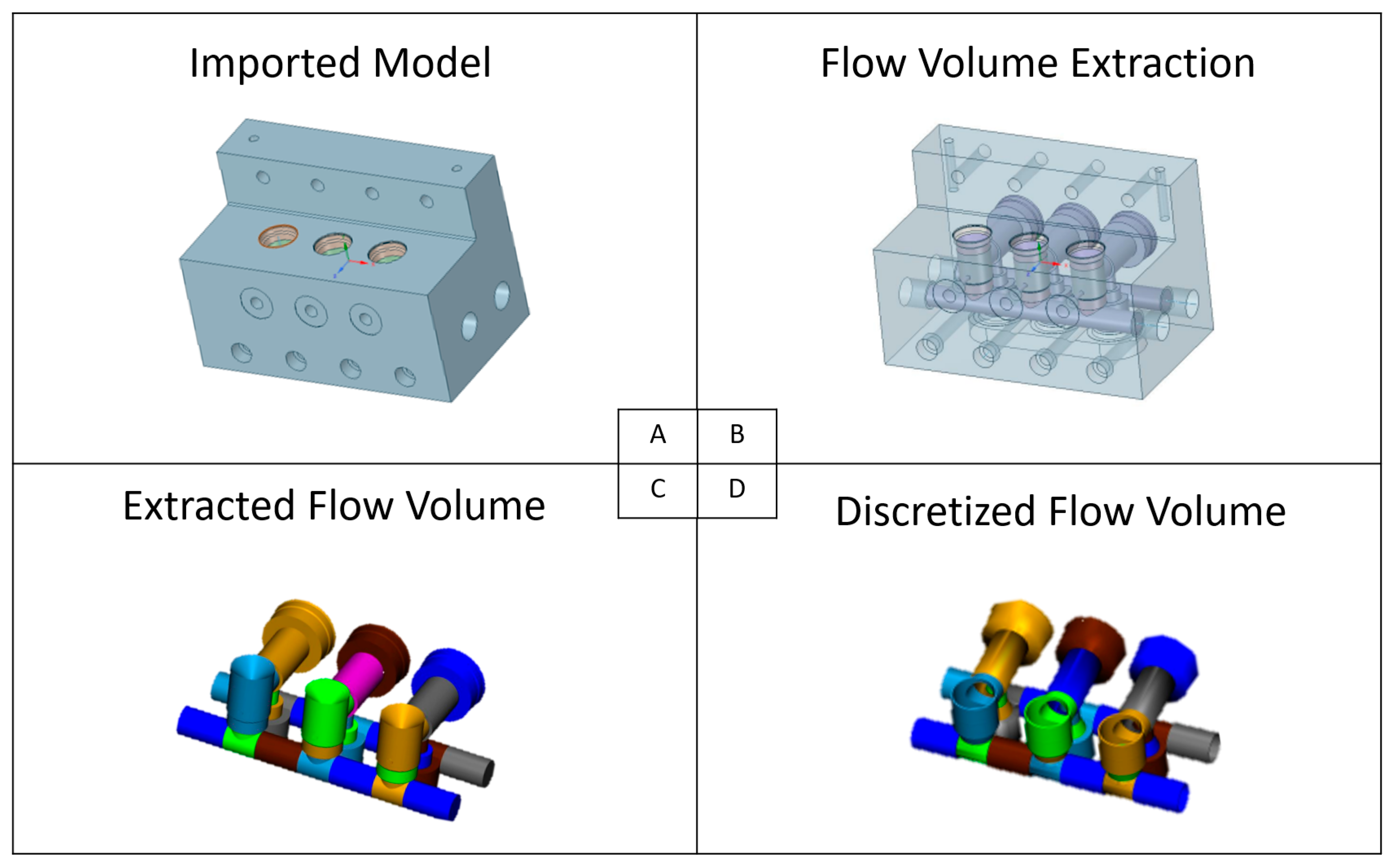
The pistons were modeled with built-in templates, which included leakage past the piston based on machined clearances. The process of discretizing the flow volumes from the 3D computer-aided design (CAD) model is shown in Figure 11; (a) First, the model is imported in the GT-Spaceclaim software, (b) the negative space of the valve block is then created into a solid model, (c) this flow volume is extracted from the original valve block and is imported into the GEM3D software from the GT-Suite package, (d) Finally, this negative space was then converted into individual components that could be connected to the pumping chamber in the model. The components representing the flow volumes in the simulation model are outlined in grey dashed lines in Figure 10. This method allowed the simulation to be based on the same 3D CAD model used to construct the valve block, maximizing the accuracy of surface areas and edges, which affected the fluid friction and thermal losses in the simulation.
Simulations were run using the inline piston model with inputs replicating the experimental conditions. The results were compared to the experimental data to validate the model. With high efficiency across the entire displacement range being this technology’s primary design goal, the simulation’s total efficiency was the main metric used to validate the model. For each simulation case, the percent displacement versus total efficiency data trended very well with experimental results with a minimum coefficient of determination (R^2) of 0.85. The results of the correlation study are shown below in Figure 12, varying shaft speed from 300 to 500 rpm at various pressures: (a) 35 bar, (b) 70 bar, and (c) 100 bar.
3.4.4. Mechanically Actuated Digital Radial Piston Pump Model
Using the same modeling techniques validating the operating strategies of the digital inline piston pump, a new model was created to evaluate the potential of the mechanically actuated digital radial piston pump, shown in Figure 13. The digital radial piston pump model includes five pumping elements. Similar to the inline piston pump, the flow geometries of the pump were extracted from the 3D model to ensure a close correlation to the actual flow geometries that would be created if the model was developed for proof-of-concept testing. The inlet and outlet valves on the five-piston pump model were created using flapper valves. The pump is modeled using positive sealing flapper valves, used to simulate the modified mechanical sun hydraulics DTDA-XCN valve. The same characteristics of the valve and mechanical properties of the valve modifications (spring rate and constant) were used in the development of the radial piston pump. This same modeling strategies for implementing the mechanical cams were used from the inline piston pump model. However, there were some fundamental changes in the final radial piston pump model. These changes included replacing the outlet check valve on the inline piston pump model with on-off valves and cams identical to those used on the inlet port. This change was required for the unit to be capable of pump and motoring capabilities.
4. Results
To evaluate the potential performance of the pump, the overall efficiency was calculated using the mechanical and volumetric efficiencies extracted from each of the simulation models for comparison. The overall efficiencies were calculated using the equations of mechanical and volumetric efficiency. The mechanical efficiency, , was calculated using the theoretical torque required by the pump and actual torque of the pump, shown in Equation (1). The theoretical torque, , Equation (2), was calculated using the volumetric displacement, , the pressure differential, , over one shaft rotation, whereas the actual torque, , is extracted from the simulation results.
The volumetric efficiency, , is calculated using the theoretical flow relative to the actual flow of the pump, shown in Equation (3). The theoretical flow, , is calculated using Equation (4), using the volumetric efficiency and the pump’s shaft speed, N, and the displacement, D. Like the actual torque, the actual flow of the pump, , is extracted from the simulation results.
The overall efficiency is calculated using the volumetric and mechanical efficiencies calculated in Equations (1) and (3), shown in Equation (5).
This was used to calculate the overall efficiency of the pump at various pressures and shaft speeds. The simulation results showed that the unit behaved as expected across the various conditions; as the simulated load on the system increased, the efficiency increased, as shown in Figure 14a, this is due to the increase of power output compared to the frictional losses in the system, which are not as significant at higher loads. As the shaft speed increased, the efficiency began to decrease, shown in Figure 14b. This is caused by an increase in frictional losses in the system at high shaft speeds.
After validating the final pump results against previous pump models/test data and comparing the simulation data’s consistency against expected pressure and shaft speed trends, the model was considered consistent with what one could expect from experimental data. Thus, the model was considered sufficiently validated for the sake of proof of concept, and a sensitivity study was analyzed on various parameters chosen for the mechanically actuated valve system to better understand the parameters that have the most significant impact on the pump efficiency to optimize the system. The results of the sensitivity analysis are discussed in the following section.
Sensitivity Analysis
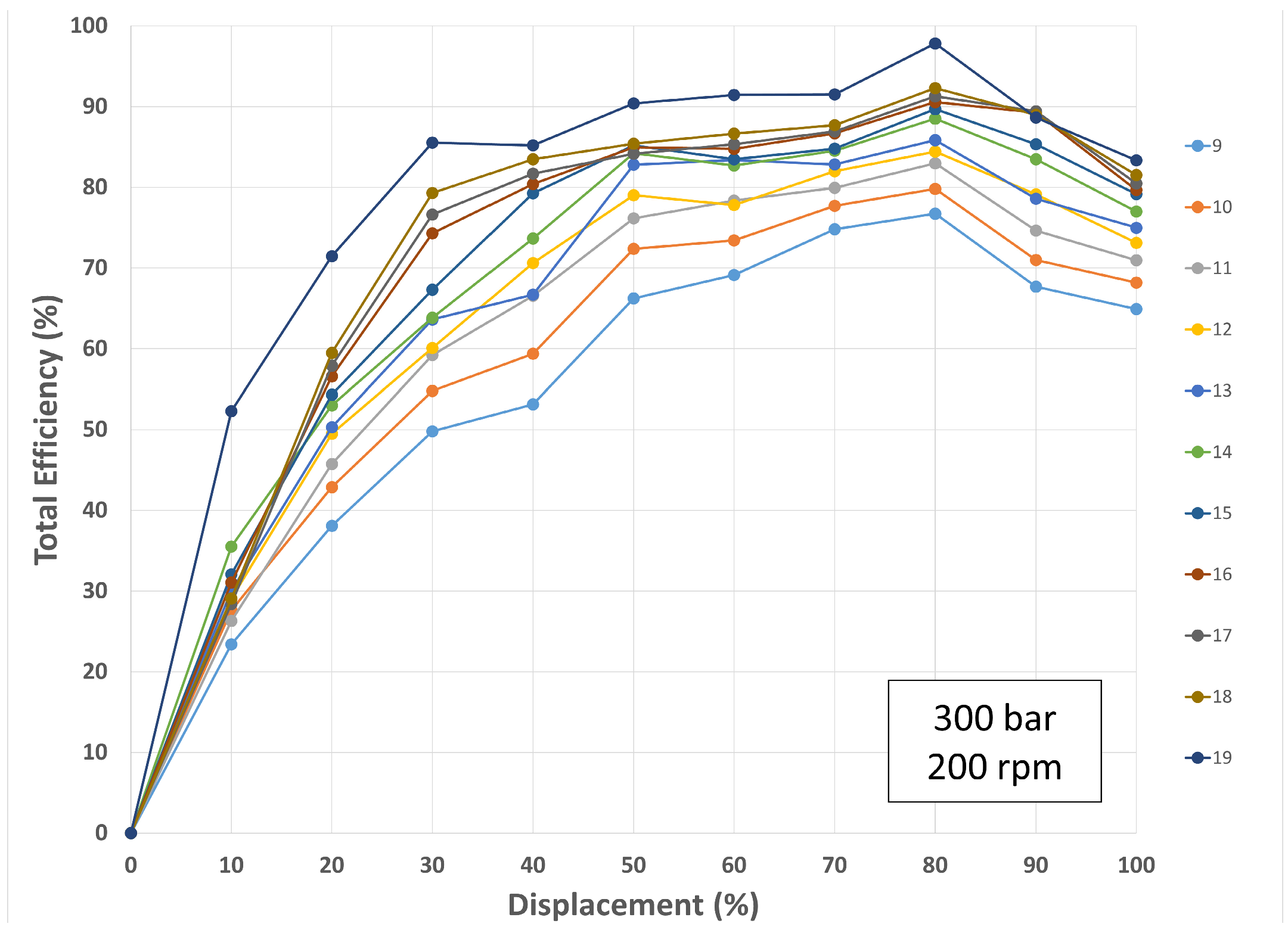
To maximize the efficiency across the displacement of the pump, a sensitivity study was conducted on various parameters to determine those with the greatest effect on the efficiency. The first parameter that was analyzed was the diameter of the valve bore. When increasing the diameter of the valve bore, it was determined that the greater the flow volume, the greater the efficiency that could be reached, as shown in Figure 15. This is determined to be attributed to the losses caused by the flow-diverting strategy that is mitigated with larger flow geometries, which can be maximized using a mechanically actuated system as opposed to electrically actuated systems. This is because electrically actuated systems could be limited by the electrical inductance of the solenoid.
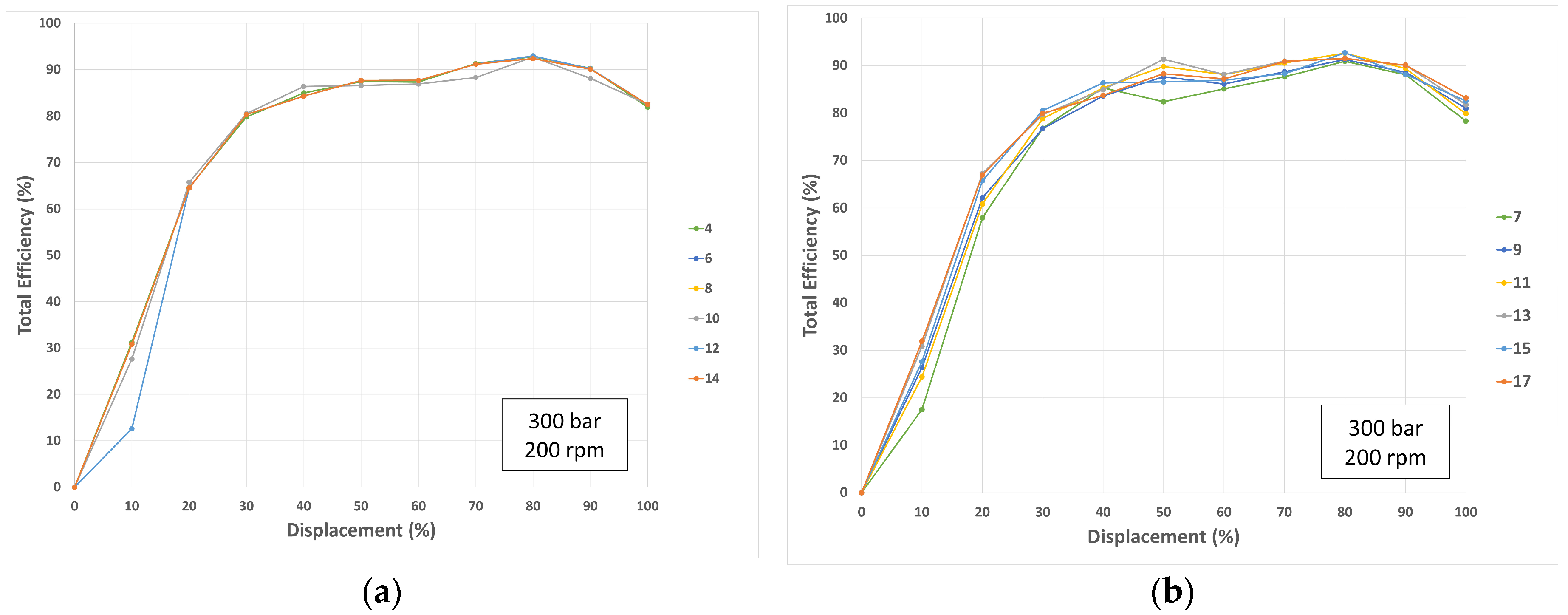
The next parameters that were evaluated as potential variables that could affect the system’s efficiency was the transition angle and compression angle of the half-masking cams. The compression angle determines the amount of shaft rotation prior to opening the valve. The transition angle of the cam determines the amount of shaft rotation between when the valve begins to open and is fully open or when the valve begins to close or is fully closed. An optimal compression angle allows the piston to pre-compress the fluid to match the system pressure or decompress the fluid and recover energy during pumping. The transition angle seemed to have a much smaller impact on efficiency across the pump’s range of displacement than the valve geometry. However, larger transition angles showed a potential increase in efficiency at lower displacements between 0–20 percent, as shown in Figure 16a. The compression angle showed an impact across the full displacement of the pump can vary across the displacement of the machine. Various compression angles were simulated to find the optimal angle for the system. The results revealed that an optimal compression angle for this pump was achieved between 7 and 17 degrees, as shown in Figure 16b.
The final characteristics of the sensitivity analysis that were simulated and observed were the change in piston diameter and dead volume within the piston chamber. The piston diameter showed a significant increase in efficiency at 20 mm diameter but decreased as the piston diameter increased further, shown in Figure 17a. This is likely caused by the initial piston sizing (20 mm) chosen based on the desired displacement of the pump. However, the sensitivity study gives a better insight into the impact that the piston diameter has on the other parameters for finalizing the design and future prototyping. The dead volume also showed a significant impact on efficiency across the bandwidth of the displacement. As expected, for much of the displacement of the pump, efficiency increased as dead volume decreased in the pump. This is caused by compression losses as the volume increases in the pumping chamber, shown in Figure 17b.
Combining what was learned from the sensitivity study, a simulation was run with the optimized parameters to evaluate the peak possible efficiency of the pump. The results show that the pump could reach a maximum efficiency of around 93% and operate above 82% efficiency for most of its displacement (~30–100%) shown in Figure 18.
5. Discussion
The optimized parameters analyzed in the system were evaluated separately to understand the attributes that had the greatest contribution in improving the efficiency of the pump and mechanically actuated system. Table 2 below shows the list of optimized parameters in the development of the mechanically actuated digital radial piston pump.
While combining the individual optimized parameters might not provide an overall optimum solution to the performance, it provides valuable insight into the further analysis and investigation of mechanically actuated systems. A multi-dimensional optimization method may be needed to find the true optimum solution for reaching the pump’s full potential. However, the system shows significant potential to improve efficiency over typical axial piston pumps. The model discussed in this article will be used to continue evaluating other possible hydraulic configurations that could enable more potential for the pump.
Overall, the results of the simulation were consistent with the results that were expected. The simulation results showed that the system experienced increased noise at the inlet and outlet ports when the outlet on-off valve was actuated. This is because the check valves consistently opened at the same cracking pressure while the on-off valves experienced a pressure differential across the valve that was dependent on valve timing. Further tuning of the outlet valve cam compression angle could help decrease this noise. The total input torque required to operate the pump increased as expected due to the additional force required to actuate the on-off valve and friction between the cam and valve stem. The impact of this is most notable at 100% displacement, as shown in Figure 19, where a drop in efficiency can be observed in comparison to the typical axial piston pumps; however, more work could be done to optimize the efficiency of the system to reach a higher peak efficiency at 100% displacement.
In conclusion, a mechanically actuated pump configuration, presented in this paper, was evaluated using sensitivity analysis to evaluate the feasibility of a manufacturable mechanically actuated digital pump that could reach higher efficiencies than typical axial piston pumps on the market. The hydraulic configuration used on this pump has two mechanically actuated on/off valves on the inlet and outlet valves, allowing the pump to achieve both pumping and motoring strategies. The peak efficiency the pump was able to reach was about 93% displacement and stays above 80% efficiency across 70% the bandwidth of its displacement.
Author Contributions
Conceptualization, K.P., J.R.M., F.B. and J.L.; methodology, J.R.M. and J.L.; investigation, K.P. and J.R.M.; writing—original draft preparation, K.P. and J.R.M.; writing—review and editing, K.P., J.R.M., F.B., T.S. and J.L; supervision, F.B., T.S. and J.L.; funding acquisition, F.B., T.S. and J.L.; All authors have read and agreed to the published version of the manuscript.
Funding
This research received funding from the Purdue Polytechnic Research Impact Area (RIA) Graduate Research Assistantship (GRA) program and the NFPA Education and Technology Foundation under award #A006402007.
Data Availability Statement
Data is available upon request from the corresponding author, F.B.
Conflicts of Interest
The authors declare no conflicts of interest.
References
- Hannappel, R. The impact of global warming on the automotive industry. In A.I.P. Conference Proceedings; A.I.P. Publishing L.L.C.: College Park, MD, USA, 2017; Volume 1871, p. 060001. [Google Scholar]
- Friedman, L.E.P.A. Announces Tightest-Ever Auto Pollution Rules. The New York Times. 2021. Available online: https://www.nytimes.com/2021/12/20/climate/tailpipe-rules-climate-biden.html (accessed on 13 December 2022).
- The White House. FACT SHEET: President Biden Sets 2030 Greenhouse Gas Pollution Reduction Target Aimed at Creating Good-Paying Union Jobs and Securing U.S. Leadership on Clean Energy Technologies; The White House: Washington, DC, USA, 2021. Available online: https://www.whitehouse.gov/briefing-room/statements-releases/2021/04/22/fact-sheet-president-biden-sets-2030-greenhouse-gas-pollution-reduction-target-aimed-at-creating-good-paying-union-jobs-and-securing-u-s-leadership-on-clean-energy-technologies/ (accessed on 13 December 2022).
- EPA. Sources of Greenhouse Gas Emissions; United States Environmental Protection Agency: Washington, DC, USA, 2022. Available online: https://www.epa.gov/ghgemissions/sources-greenhouse-gas-emissions (accessed on 15 November 2022).
- TransportPolicty.net (n.d.) US: NONROAD: EMISSIONS. Available online: https://www.transportpolicy.net/standard/us-nonroad-emissions/ (accessed on 7 November 2023).
- Stelson, K.A. Academic fluid power research in the USA. Int. J. Hydromechatron. 2018, 1, 126–152. [Google Scholar] [CrossRef]
- Achten, P. Convicted to innovation in fluid power. Proc. Inst. Mech. Eng. Part I J. Syst. Control Eng. 2010, 224, 619–621. [Google Scholar] [CrossRef]
- Love, L.J.; Lanke, E.; Alles, P. Estimating the Impact (Energy, Emissions and Economics) of the US Fluid Power Industry; Oak Ridge National Laboratory: Oak Ridge, TN, USA, 2012. [Google Scholar] [CrossRef]
- Lynch, L.; Zigler, B. Estimating Energy Consumption of Mobile Fluid Power in the United States; United States Department of Energy: Washington, DC, USA, 2017. [Google Scholar] [CrossRef]
- Vacca, A. Energy efficiency and controllability of fluid power systems. Energies 2018, 11, 1169. [Google Scholar] [CrossRef]
- Khalil, M.K.B.; Yurkevich, V.D.; Svoboda, J.; Bhat, R.B. Implementation of single feedback control loop for constant power regulated swash plate axial piston pumps. Int. J. Fluid Power 2002, 3, 27–36. [Google Scholar] [CrossRef]
- Gannon, M. What Is the Difference between Fixed and Variable Pumps? Mobile Hydraulic Tips a Fluid Power World Resource. 2019. Available online: https://www.mobilehydraulictips.com/what-is-the-difference-between-fixed-and-variable-pumps/ (accessed on 12 February 2023).
- Kim, J.-K.; Kim, H.-E.; Lee, Y.-B.; Jung, J.-Y.; Oh, S.-H. Measurment of fluid film thickness on the valve plate in oil hydraulic axial piston pumps (Part II: Spherical design effects). J. Mech. Sci. Technol. 2005, 19, 655–663. [Google Scholar] [CrossRef]
- Ehsan, M.; Rampen, W.H.S.; Salter, S.H. Modeling of digital-displacement pump-motors and their application as hydraulic drives for nonuniform loads. J. Dyn. Syst. Meas. Control 2000, 122, 210–215. [Google Scholar] [CrossRef]
- Budden, J.J.; Williamson, C. Danfoss digital displacement® excavator: Test results and analysis. In Fluid Power Systems Technology; American Society of Mechanical Engineers: New York, NY, USA, 2019; Volume 59339, p. V001T01A032. [Google Scholar]
- Pavlis, V.; McMillan, C.; Nørgård, C.; Caldwell, N.J. Digital Displacement Motoring Characteristics of Dynamic Energy Recovery and Hydraulic Transformation. In Fluid Power Systems Technology; American Society of Mechanical Engineers: New York, NY, USA, 2023; Volume 87431, p. V001T01A063. [Google Scholar]
- Holland, M.A. Design of Digital Pump/Motors and Experimental Validation of Operating Strategies. Ph.D. Thesis, Purdue University, West Lafayette, IN, USA, 2012. [Google Scholar]
- Merrill, K.J. Modeling and Analysis of Active Valve Control of a Digital Pump-Motor. Ph.D. Thesis, Purdue University, West Lafayette, IN, USA, 2012. [Google Scholar]
- Pate, K.S. Design and Simulation of Digital Radial Piston Pumps Using Externally Actuated Cam Systems. Master’s Thesis, Purdue University Graduate School, West Lafayette, IN, USA, 2022. [Google Scholar]
- Breidi, F.; Helmus, T.; Lumkes, J. The impact of peak-and-hold and reverse current solenoid driving strategies on the dynamic performance of commercial cartridge valves in a digital pump/motor. Int. J. Fluid Power 2016, 17, 37–47. [Google Scholar] [CrossRef]
- Chehade, A.; Breidi, F.; Pate, K.S.; Lumkes, J. Data-Driven Adaptive Thresholding Model for Real-Time Valve Delay Estimation in Digital Pump/Motors. Int. J. Fluid Power 2019, 20, 271–294. [Google Scholar] [CrossRef]
- Helmus, T. Investigation and Implementation of Mechanically Actuated Valves for Digital Hydraulic Units. Ph.D. Thesis, Purdue University, West Lafayette, IN, USA, 2017. [Google Scholar]
- Helmus, T.; Breidi, F.; Lumkes, J., Jr. Simulation of a variable displacement mechanically actuated digital pump unit. In Proceedings of the Eighth Workshop on Digital Fluid Power, Tampere, Finland, 24–25 May 2016; pp. 95–105. [Google Scholar]
Figure 1.
(a) Electromagnetic solenoid valves used on Artemis Technology [14]; (b) Modern development of Artemis Technology on Danfoss Digital Displacement pump [15].

Figure 2.
(a) Digital displacement unit using on/off solenoid valves developed at Purdue University [18]; (b) Testing of Purdue’s electrically actuated digital displacement pump [18].

Figure 3.
(a) Mechanical half-masking cams; (b) Cam phasing mechanism for the mechanically actuated digital inline piston pump [22].
Figure 3.
(a) Mechanical half-masking cams; (b) Cam phasing mechanism for the mechanically actuated digital inline piston pump [22].

Figure 4.
(a) Efficiency comparison of mechanically actuated valve systems to electrically actuated valve systems [22]; (b) Testing of the mechanically actuated inline digital piston pump at Purdue University [22].

Figure 5.
Valve states imposed by combination of two half masking cams to achieve 50 percent displacement.
Figure 5.
Valve states imposed by combination of two half masking cams to achieve 50 percent displacement.

Figure 6.
Digital radial piston pump circuit (50% displacement).

Figure 7.
Depiction of the partial flow diverting phases at 50% displacement using half-masking cams on the inlet and outlet ports of the pump.
Figure 7.
Depiction of the partial flow diverting phases at 50% displacement using half-masking cams on the inlet and outlet ports of the pump.

Figure 8.
(a) Isometric view of the mechanically actuated displacement control system; (b) Breakdown of displacement control phasing mechanism.
Figure 8.
(a) Isometric view of the mechanically actuated displacement control system; (b) Breakdown of displacement control phasing mechanism.

Figure 9.
(a) Mechanically actuated digital pump housing; (b) Cross-section of the mechanically actuated system inside of the pump housing.
Figure 9.
(a) Mechanically actuated digital pump housing; (b) Cross-section of the mechanically actuated system inside of the pump housing.

Figure 10.
Digital inline piston pump model with mechanically actuated valves on the inlet ports and check valves on the outlet ports.
Figure 10.
Digital inline piston pump model with mechanically actuated valves on the inlet ports and check valves on the outlet ports.

Figure 11.
Process of discretizing the flow geometries within GT Suite: (A) Imported model in GT Spaceclaim; (B) Flow geometry extraction in GT Spaceclaim; (C) Extracted flow volume in GEM3D; (D) Discretized flow volume in GEM3D.
Figure 11.
Process of discretizing the flow geometries within GT Suite: (A) Imported model in GT Spaceclaim; (B) Flow geometry extraction in GT Spaceclaim; (C) Extracted flow volume in GEM3D; (D) Discretized flow volume in GEM3D.

Figure 12.
Hydraulic Efficiency at various displacements, shaft speeds and pressures (a) 35 bar; (b) 70 bar; (c) 100 bar.
Figure 12.
Hydraulic Efficiency at various displacements, shaft speeds and pressures (a) 35 bar; (b) 70 bar; (c) 100 bar.

Figure 13.
Digital radial piston pump with mechanically actuated valves on inlet and outlet ports.

Figure 14.
Mechanically actuated digital radial piston pump’s total efficiency at various displacements; varying (a) pressure (bar); (b) shaft speed (rpm).
Figure 14.
Mechanically actuated digital radial piston pump’s total efficiency at various displacements; varying (a) pressure (bar); (b) shaft speed (rpm).

Figure 15.
Sensitivity analysis of total efficiency with respect to displacement varying valve bore size (mm).
Figure 15.
Sensitivity analysis of total efficiency with respect to displacement varying valve bore size (mm).

Figure 16.
Sensitivity analysis of total efficiency with respect to displacement varying (a) cam transition angle, (b) compression angle.
Figure 16.
Sensitivity analysis of total efficiency with respect to displacement varying (a) cam transition angle, (b) compression angle.

Figure 17.
Sensitivity analysis of total efficiency with respect to displacement varying (a) piston diameter and (b) dead volume in the pumping chamber.
Figure 17.
Sensitivity analysis of total efficiency with respect to displacement varying (a) piston diameter and (b) dead volume in the pumping chamber.

Figure 18.
Optimized parameters of a mechanically actuated digital radial piston pump with dual half masking cam set.
Figure 18.
Optimized parameters of a mechanically actuated digital radial piston pump with dual half masking cam set.

Figure 19.
Efficiency comparison of typical axial piston pump to optimized mechanically actuated digital radial piston pump with dual half masking cam sets.
Figure 19.
Efficiency comparison of typical axial piston pump to optimized mechanically actuated digital radial piston pump with dual half masking cam sets.


Table 1.
Comparison of mechanically and electrically actuated valving systems.
| Mechanically Actuated vs. Electrically Actuated Valving Systems | |
|---|---|
| Benefits | Limitations |
| Eliminates Data Acquisition Systems | Added Cam Friction |
| Eliminates Added Energy Sources | Cam Lubrication Needed |
| Eliminates Valve Delay | Sequential Flow Diverting (Not Possible) |
| Simple control systems | Sequential Limiting Strategies (Not Possible) |
Table 2.
Individually optimized parameters via sensitivity analysis.
| Parameter | Range |
|---|---|
| Valve bore diameter | 9–19 mm |
| Cam transition angle | 4–14 degrees |
| Cam Compression angle | 7–17 degrees |
| Piston diameter | 20 mm |
| Dead Volume | 30–44 cm |
Disclaimer/Publisher’s Note: The statements, opinions and data contained in all publications are solely those of the individual author(s) and contributor(s) and not of MDPI and/or the editor(s). MDPI and/or the editor(s) disclaim responsibility for any injury to people or property resulting from any ideas, methods, instructions or products referred to in the content. |
© 2024 by the authors. Licensee MDPI, Basel, Switzerland. This article is an open access article distributed under the terms and conditions of the Creative Commons Attribution (CC BY) license (https://creativecommons.org/licenses/by/4.0/).
Share and Cite
MDPI and ACS Style
Pate, K.; Marschand, J.R.; Breidi, F.; Salem, T.; Lumkes, J. Design and Sensitivity Analysis of Mechanically Actuated Digital Radial Piston Pumps. Processes 2024, 12, 504. https://doi.org/10.3390/pr12030504
AMA Style
Pate K, Marschand JR, Breidi F, Salem T, Lumkes J. Design and Sensitivity Analysis of Mechanically Actuated Digital Radial Piston Pumps. Processes. 2024; 12(3):504. https://doi.org/10.3390/pr12030504
Chicago/Turabian StylePate, Keith, James R. Marschand, Farid Breidi, Tawfiq Salem, and John Lumkes. 2024. "Design and Sensitivity Analysis of Mechanically Actuated Digital Radial Piston Pumps" Processes 12, no. 3: 504. https://doi.org/10.3390/pr12030504
Note that from the first issue of 2016, this journal uses article numbers instead of page numbers. See further details here.