
Electrolytic Regeneration of Spent Caustic Soda from CO2 Capture Systems


1
Engineering & Energy, College of Science Health Engineering and Education, Murdoch University, Perth, WA 6150, Australia
2
CSIRO Environment, 147 Underwood Avenue, Floreat, WA 6014, Australia
*
Authors to whom correspondence should be addressed.
Processes 2024, 12(4), 723; https://doi.org/10.3390/pr12040723
Submission received: 18 February 2024
/
Revised: 23 March 2024
/
Accepted: 25 March 2024
/
Published: 2 April 2024
(This article belongs to the Special Issue Recent Advances in Modern Carbon-Negative Technologies for CO2 Capture)
Abstract
:The traditional electrochemical caustic soda recovery system uses the generated pH gradient across the ion exchange membrane for the regeneration of spent alkaline absorbent from CO2 capture. This electrochemical CO2 capture system releases the by-products H2 and O2 at the cathode and anode, respectively. Although effective for capturing CO2, the slow kinetics of the oxygen evolution reaction (OER) limit the energy efficiency of this technique. Hence, this study proposed and validated a hybrid electrochemical cell based on the H2-cycling from the cathode to the anode to eliminate the reliance on anodic oxygen generation. The results show that our lab-scale prototype enabled effective spent caustic soda recovery with an electron utilisation efficiency of 90%, and a relative carbonate/bicarbonate diffusional flux of approximately 40%. The system also enabled the regeneration of spent alkaline absorbent with a minimum electrochemical energy input of 0.19 kWh/kg CO2 at a CO2 recovery rate of 0.7 mol/m2/h, accounting for 30% lower energy demand than a control system without H2-recycling, making this technique a promising alternative to the conventional thermal regeneration technology.
1. Introduction
Global warming has emerged as one of the major environmental challenges facing the world. Carbon dioxide (CO2) is the key greenhouse gas that drives global warming and accounts for approximately 55% of observed global warming [1]. The CO2 concentration in the atmosphere has increased by 3% since 1950 [2]. To combat global warming, deploying carbon capture technologies to reduce the carbon footprint is imperative. Direct air capture (DAC) and point-source capture from existing CO2 have been extensively reviewed with detailed analysis determining energy efficiency, chemical principle, and commercial viability [3,4,5,6,7].
Several mature carbon capture technologies are commercially available [8,9,10,11,12]. Among these technologies, chemical absorption with alkaline hydroxide solutions (NaOH or KOH) is the most common CO2 separation method employed by industrial large-scale plants [13,14]. In this process, the CO2-rich gas stream is pressurised and passed into the absorption tower. The CO2 dissolves into the liquid phase and chemically reacts with the alkali according to the following reaction:
CO2 + 2 NaOH → Na2CO3 + H2O
ΔH0 = −109.4 kJ/mol
Previous studies showed high capture yields ranging from 90 to 99% [15,16,17]. After reaching CO2 saturation capacity, the spent sorbent is regenerated, either by a temperature swing or pressure swing, leading to a high-purity CO2 gas stream. After CO2 stripping, the regenerated CO2-lean solvent is pumped back into the absorber for another cycle [18,19]. The conventional regeneration of spent sorbent, which implies the conversion of sodium carbonate to sodium hydroxide, requires an energy input of 1.1 kWh/kg CO2, whereas the thermodynamic minimum energy required is 0.69 kWh/kg CO2 [20,21]. The comparatively high energy consumption and low regeneration efficiency (<90%) of conventional regeneration technologies [22] necessitate the development of more efficient technologies for CO2 capture.
Alternative methods have been explored to reduce energy requirements. CO2 capture and release through an electrochemical process may offer a solution to address these drawbacks. The fundamental of this technology in CO2 capture relies upon aqueous acid-base neutralisation pathways. An electrochemically generated pH gradient between the cathode and anode chambers is the primary driver for CO2 capture and recovery. The anode and cathode chambers are typically separated by an Anion Exchange Membrane (AEM) allowing ion migration while providing the individual electrode physical compartments. After CO2 absorption in an alkaline solution, CO2 generates carbonate ions. The entire reactions involved in the CO2 absorption could be written in ionic terms as follows:
CO2(g) ↔ CO2(aq)
H2O ↔ OH− + H+
The spent sorbent containing is then pumped into the cathode compartment. The (bi)carbonate species migrate through the AEM under an electric field towards the anode compartment. The pH decrease caused by the anodic half-reaction results in the conversion of carbonate to carbonic acid, which then decomposes to form CO2:
In this context, various cell configurations have been introduced in recent years. An early attempt was made by Walke et al. [23] to separate CO2 from flue gas using an electrochemical cell to drive CO2, in the forms of (bi)carbonate species, across an AEM into a CO2-recovery stream. Another approach used an oxygen cycling electrochemical cell to produce a CO2-rich effluent from the combustion of fossil fuel [24]. Recently, an alkaline water electrolyser was employed to remove CO2 from biogas [25]. Mohammadpour et al. [26] developed a three-chamber electrochemical cell that enabled the recovery of CO2 in an intermediate chamber to prevent CO2 contamination of the anodic O2 outlet gas.
Theoretically, the electrolysis of water in standard conditions requires thermodynamic minimum energy of 237 kJ/mol (equivalent to a cell voltage of 1.23 V) [27]. In practice, additional energy is also required to overcome activation overpotential, mainly from intrinsic kinetic barriers associated with half-reactions at each electrode, particularly at the anode [28,29]. Taking all overpotentials into account, the cell voltage of a typical alkaline electrolyser varies between 1.8 V and 2.4 V [30,31]. However, electrolytic H2 and O2 formation during pH gradient generation in the electrochemical cell may not be desirable and may present additional obstacles to the CO2 removal process. For example, co-mixing H2 and CH4 when using the alkaline water electrolyser for CO2 removal from anaerobic digester biogas could present some challenges, including increased probability of ignition, material degradability in contact with H2, and leakage [32].
Additionally, oxygen formation is a kinetically sluggish reaction that often demands significantly higher voltage compared to the thermodynamic minimum voltage at a given current density [33]. Therefore, it is necessary to improve the energetic performance of the electrochemical CO2 capture technique in order to make it competitive and practical. Recently, Muroyama et al. [34] developed an electrochemical hybrid cell powered by H2 cycling from the cathode to the anode to generate a pH gradient for CO2 capture from a wide range of gas mixtures. Their approach takes advantage of replacing the oxygen evolution reaction (OER) at the anode with the spontaneous hydrogen oxidation reaction (HOR).
In the hybrid cell, the generated H2 at the cathode is fed into the anode to substitute the sluggish OER. Each half-cell reaction can be represented as follows:
Cathode:
2 H2O + 2e− → H2 + 2OH−
Anode:
H2 + 2OH− → 2H2O + 2e−
Thermodynamically, this electrochemical cell can be operated at a cell voltage of zero if the hydrogen pressure difference between the cathode and anode side is zero (Nernst equation). However, a wide pH gradient between two compartments required for carbon equilibrium kinetics and overpotentials such as activation and ohmic overpotentials causes an increase in minimum energy requirement.
The previous study demonstrated that CO2 separation can be achieved using the described electrochemical cycles [34]. However, further research is still required to identify the challenges and explore the potential of this technique for commercial use. Therefore, this study aimed to fill these gaps through a series of experiments to characterise the performance of a lab-scale electrochemical hybrid cell for CO2 capture. In particular, comparison of the energy demand between the water electrolyser system and the hybrid cell for regeneration of spent alkaline solution for CO2 capture was conducted. We also identified the effect of key operational parameters, including H2 loading rate into the anode compartment, back diffusion, and H2 utilisation rate, on the performance of the electrochemical hybrid cell.
2. Experimental Section
2.1. Materials
All materials were used as delivered without any further treatments (Figure 1). All the chemical reagents used were analytic-grade reagents purchased from Chem-Supply, Australia (Gillman, Australia). A commercial anion exchange membrane (AMI-007, Membranes International Inc., Ringwood, NJ, USA) was used for the experiments carried out in this study. Platinised carbon cloth electrodes with a Pt loading of 0.2 mg/cm2 and thickness of 0.365 mm and woven carbon cloth with a microporous layer with a thickness of 0.410 mm were purchased from Fuelcellstore (Bryan, TX, USA). Graphite plates with the serpentine flow field were machined out by Rongxing Group (Zhengzhou, China). Each flow field channel was 50 mm long, 2 mm wide and 3 mm deep. The ribs that formed the channels were 2 mm wide. The Viton® fluoroelastomer gasket (Fuel cell store, Bryan, TX, USA) was used in cell fabrication to ensure a good seal.
2.2. Hybrid Cell Fabrication and Testing
The experiments were carried out using a two-compartment apparatus with an active surface area of 25 cm2. Two commercial platinised carbon cloth electrodes with a loading of 0.2 mg Pt/cm2 (Fuel Cell Store) were employed as the catalytic site of the anode and cathode and were placed against the membrane. A graphite plate with integrated serpentine flow channels (1 mm width and 1 mm depth) was used as the current collector and structural support on the cathode side. Two commercial woven carbon cloths were employed at the anode and cathode as a gas diffusion layer (GDL) to decrease the contact resistance between catalytic sites and the current collector. The whole cell was encased between a graphite plate with flow fields (anode) and a Perspex plate (cathode) using incompressible Polytetrafluoroethylene (PTFE) gaskets. A pocket with a working volume of 50 mL was manufactured on the cathode Perspex plate to provide a water layer for the H2 formation reaction. The cell was compressed using 8 bolts and torque value of 5 N.m.
Tests in this work were conducted with a bicarbonate-rich solution, as each bicarbonate ion molecule carries one CO2 per one negative charge, thereby it may achieve a high CO2 diffusional flux to electron ratio for the electrolysis process. The NaHCO3 solution (1 M) was recirculated continuously from a tank to the cathode side by a peristaltic pump to sustain (bi)carbonate concentration.
The membrane was soaked in 0.5 M NaHCO3 solution for 24 h prior to operation. In the hybrid cell mode operation, H2 gas was fed via a peristaltic pump (7554-95 Masterflex, Vernon Hills, IL, USA) from a non-reactive Tedlar gas sampling bag (CEL Scientific Corp., Santa Fe Springs, CA, USA) into the flow field of the anode side. To avoid dehydration of the membrane, the inlet hydrogen stream to the anode was passed through a humidifier at 50 °C. In the water electrolysis mode, H2 feed to the anode was replaced by 1 M of NaHCO3 solution. The CO2 content in the outlet streams was monitored continuously using CO2 sensors (CO2 meter GC-0016, Ormond Beach, FL, USA) and accompanying software. A U-tube manometer with oil displacement connected to a Burkert solenoid valve was inserted into the gas outlet line to measure the output gas flow rate to evaluate the Faradaic efficiency and CO2 relative flux.
The electrochemical cell was coupled with a potentiostat and operated in a three-electrode configuration using a silver–silver chloride (Ag/AgCl) reference electrode mounted on the cathode side. A loop control mechanism was developed using LabViewTM 2018 version softwareto control the potentiostat, and pumps and collect the data from the probes and sensors. All experiments were performed at atmospheric pressure and room temperature of 25 ± 1 °C. In accordance with our previous study [35], the integrity of the electrochemical experiments conducted in this work was verified to assure that the data obtained were reproducible with ≤10% variation.
2.3. Calculation
To investigate the performance of the experimental setup, some operational parameters such as Faradaic efficiency, relative CO2 flux and gas permeability of membrane were calculated. Faradaic efficiency was determined based on the H2 utilisation rate on the anode side as follows (Equation (10)):
where is the difference in H2 molar flow rate (mol/s) between inlet and outlet of the anode. F (96485 A s/mol) is the Faradaic constant and I is the current (A).
The relative CO2 diffusional flux was defined as (Equation (11)):
where is the molar flow rate of CO2 recovery on the anode side (mol/s).
The H2 gas permeability of membrane (1 barrer= 10−10 cm3 cm cm−2 s−1 cmHg−1) was defined as:
where QH (cm3/s) is the flow rate of H2 diffused across the membrane, ΔPH (cmHg−1) is the partial pressure difference over the length of the membrane, and L (cm) and A (cm2) are the thickness and projected area of the membrane.
The net energy requirement for electrochemical CO2 separation (kWh/kg CO2) was calculated using the following equation:
where I is the current (A), V is the cell voltage (V), and is the rate of CO2 regeneration (kg/h).
3. Results and Discussion
3.1. Polarisation Performance
The use of cathodic H2 as an anodic electron donor is thermodynamically more favourable than the use of water leading to oxygen production. At the same time, cathodic H2 represents a practical energy source (e.g., in fuel cells). To investigate the practical benefits of sacrificing cathodic H2 and reusing it as an anodic electron donor, the current–voltage polarisation curves of the described hybrid electrochemical cell were compared with that of an alkaline water electrolyser.
The hydrogen oxidation reaction (HOR) was initiated at about −500 mV for the Pt-loaded electrode, which is close to the equilibrium potential for HOR at pH = 7 (assuming no pH gradient in the vicinity of the anode at which the equilibrium potential of HOR is −414 mV). This means that, in contrast to anodic oxygen production from water splitting, there was no substantial overpotential. The hydrogen oxidation reaction was recognised as a fast electrochemical reaction [36,37], and thus the activation polarisation loss owing to the charge transfer was close to zero. The anodic polarisation curve of the hybrid cell showed a linear behaviour (Figure 2a), indicating that the total overpotential was dominated by ohmic resistance due to ion transport, and the activation overpotential was negligible.
The polarisation curve for water oxidation at a constant anolyte pH (~8) exhibited a high activation barrier (Figure 2a). The water oxidation reaction theoretically occurred at a potential of about +700 mV based on the Pourbaix diagram of water electrolysis, whereas the onset anodic potential was between +1500 and +2000 mV. This suggests an experimental overpotential between 800 and 1300 mV. After exceeding the water oxidation potential at about 2000 mV, the current increased linearly with the anodic potential.
The cathode polarisation curves appeared similar for both electrochemical cells (Figure 2b). The higher activation overpotential observed in the cathode polarisation curve compared to that in the anode polarisation curve is attributed to slower kinetics of the Volmer–Tafel mechanism of H2 evolution reaction than that of H2 oxidation reaction [38].
It is simple and convenient to evaluate the performance of two electrochemical setups by comparing the potentials (here named indicative potential) at low current densities after which a linear relationship between voltage and current signifies a constant resistance. The main factor affecting the overpotential at indicative voltage is activation polarisation, which dominates losses at low current densities, and the impact of ohmic losses resulting from cell parts and their configuration is insignificant. In the presented experiments, this indicative potential was observed at a current density of 100 A/m2. In the alkaline water electrolyser, the indicative cell voltage required to achieve this current density of 100 A/m2 was about 3000 mV, whereas it was only 1200 mV for the hybrid cell. The additional voltage of 1800 mV needed for the alkaline water electrolyser comprises a 700 mV difference in theoretical anodic potentials between the OER in the alkaline water electrolysis cell and the HOR in the hybrid cell. Furthermore, there was an additional 1100 mV of overpotential.
At potentials higher than the indicative potential, both electrochemical cells showed a similar ohmic resistance of about 1.5 ohm.m2 across the anion exchange membrane. This means using a gas phase anode in the hybrid cell did not have a prohibitive effect on the anion transport across the AEM.
3.2. Effect of H2 Loading Rate on the Polarisation Performance of the Hybrid Cell
One of the most important technical aspects of the hybrid cell is the supplementation of sufficient H2 at the catalytic surface area of the anode to satisfy load demand. To investigate the influence of the H2 inflow rate on the polarisation curve, four hydrogen inflow rates were tested (Figure 3). By applying the Faraday calculation, the theoretical H2 consumption rates corresponding to the current densities of 100, 200, and 300 A/m2 were about 1.5, 3, and 5 mL/min, respectively (considering the surface area of 25 cm2). At a low H2 inflow rate of 1.5 mL/min (equivalent to the theoretical current density of about 100 A/m2), the anode showed a similar polarisation curve to the water oxidation reaction in Figure 2a at high current densities. This was attributable to fuel starvation on the anode side where the H2 supply could not meet the theoretical H2 demand. Thus, the HOR was substituted with the oxidation of accumulated water on the surface.
With higher H2 flow rates, the polarisation curve increasingly resembled that of the hybrid cell. A surplus hydrogen supply improved the polarisation performance of the hybrid cell by 30%. A similar trend was reported by Li et al. [39], who showed that the polarisation performance of the cell gradually increased with increasing H2 flow rates to the anode. During the H2 oxidation, the input H2 was consumed at the anode, which caused the depletion of reactant near the electrode surface, hence the kinetic limitation. The higher H2 inflow rate ensured a high hydrogen partial pressure in the anode chamber, which resulted in an increase in the drag force of convective diffusion from the diffusion layer to the catalyst layer to avoid gas transport losses [40,41].
3.3. H2 Back Diffusion across the AEM
Any H2 crossover through the AEM would decrease the efficiency of the hybrid cell. The H2 gas permeated through the AEM owing to the partial pressure gradient. The rate of gas crossover through the membranes followed Fick’s law, which is directly proportional to the diffusion coefficient and concentration gradient across the membrane and inversely related to the membrane thickness [42].
In order to measure the gas crossover rate through a dry AMI-7001 anion exchange membrane with a thickness of 0.45 mm, the H2 gas content in the cathode compartment was recorded over time in the absence of an electric field, while H2 gas was purged at atmospheric pressure on the other side of the membrane (Figure 4a). H2 crossover current densities calculated from Faraday’s laws of electrolysis in A/m2 are shown in Figure 4b. The H2 flux density was about 120 A/m2 at maximum driving from across the membrane and decreased over time as the H2 concentration on the permeate side increased, resulting in a reduction in the driving force for H2 crossover. The H2 crossover obtained in the present study was about three times higher than that measured for an AEM-based water electrolyser in Pushkareva et al. [43]. This could be attributable to the fact that the AEM employed in their measurement was hydrated, which diminished H2 diffusion across the membrane. The diffusion coefficients of H2 in water and air are 5.13 × 10⁻⁹ m2/s and 0.61 × 10⁻⁴ m2/s, respectively [44,45].
The H2 permeability of the dry AMI-7001 was also calculated (Equation (12)). Dry AMI-7001 showed a high H2 permeability of about 2500 barrer. Huang et al. [46] reported a similar H2 gas permeability using dry QPIM-1 AEM, followed by an exponential decline when the membrane was hydrated. It is worth mentioning that H2 flowed much slower through the hydrated membrane than the dry one because the water molecule occupied the flow paths of the porous media.
3.4. Faradaic Efficiency
Theoretically, the amount of H2 consumed by the anode should follow Faraday’s law, which is shown in Equation (10). During actual operation, however, possible leakage through sealing material and H2 crossover through the AEM may reduce the Faraday efficiency. Nonetheless, the result showed that high Faraday efficiency of >90% was achieved with the tested system at high current densities (Figure 5). This suggests that the H2 crossover through the hydrated AMI-7001 was insignificant at high current densities, as explained in Section 3.3. However, at lower current densities, the Faraday efficiency decreased to about 60%. Apparently, the effect of hydrogen gas leakage through the membrane or sealing material depends on the current density. Further study is required to verify this dependence.
3.5. CO2 Recovery Investigation
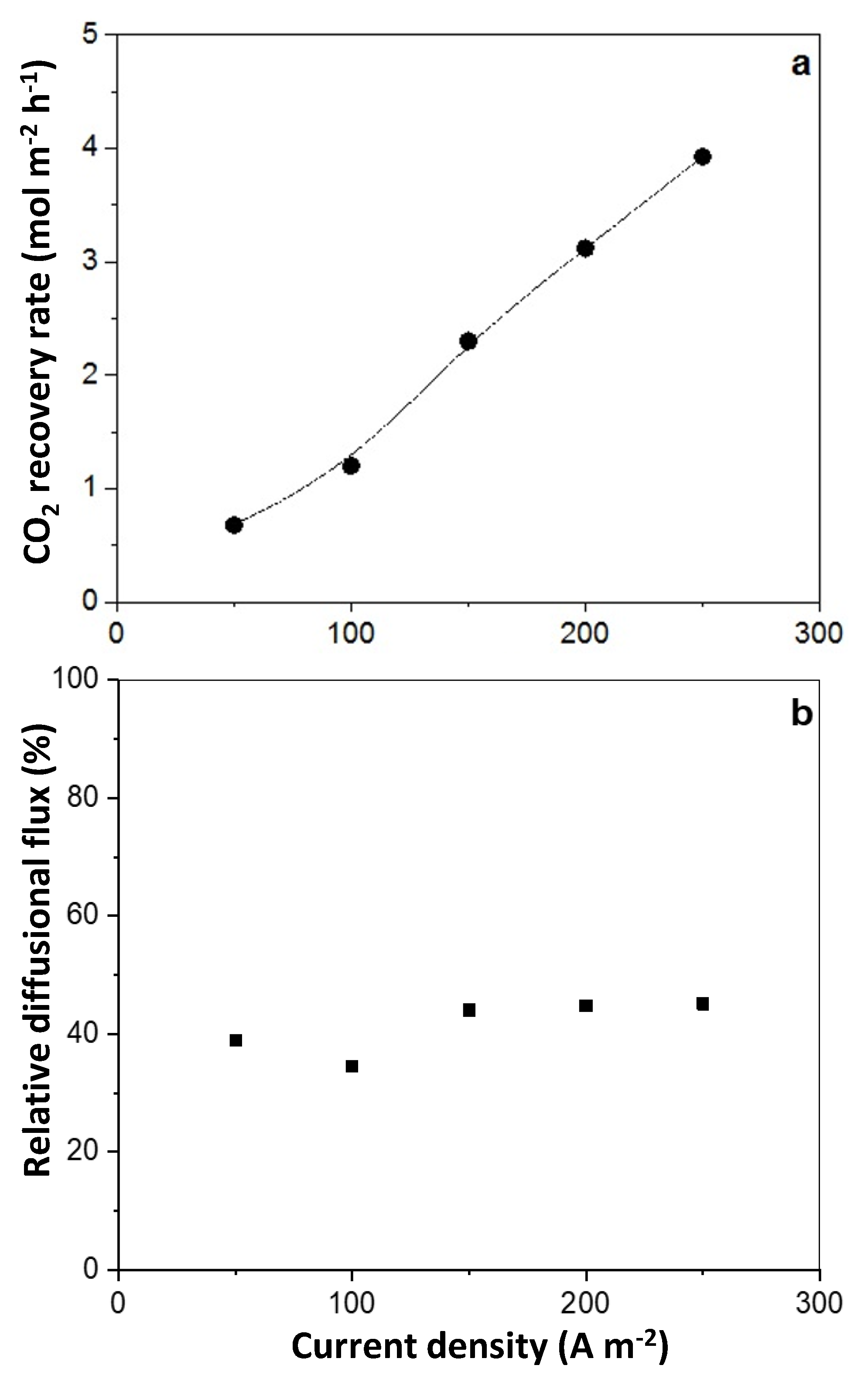
In electricity-driven CO2 removal using an AEM-based electrochemical cell, the dissolved CO2 in the catholyte, in the form of HCO3−/CO32−, is transferred through an AEM to the anolyte, where it is stripped as CO2 gas at low pHs. Previous work [35] has shown that in traditional O2-forming electrolytic cells, a catholyte pH of nine enabled high-energy-efficient CO2 transfer to the anode. In the current cell, CO2 flux at pH 9 was maintained with 1M bicarbonate solution circulating from a tank to the cathode side of the cell. CO2 flux across the AEM was determined by measuring the CO2 emission from the anode (Figure 6a). The CO2 flux across the AEM was proportional to the current density, indicating there was no concentration overpotential in the systems within the studied current densities.
In the 1 M bicarbonate solution used as catholyte in this study, the main anion to act as a charge transferring species to transport the dissolved CO2 at pH 9 is HCO3−. Hence, at a current efficiency of 100%, one Faraday of charges would theoretically transfer one mole of “CO2” as HCO3−. However, the results showed that the measured dissolved CO2 flux across the AEM accounted for only about 40% within the applied current densities (Figure 6b), which is similar to the findings reported for CO2 separation from flue gas using an O2 cycling electrochemical cell [24,47]. This relatively low efficiency proved that apart from bicarbonate, other anions participate in charge transfer across the AEM, or some CO2 gas diffuses back to the catholyte through the AEM. Hydroxyl and/or carbonate ions could contribute to some charge transfer. Considering the extremely alkaline medium near the membrane/electrode interface, where the H2 generation reaction occurs, the concentrations of hydroxyl and carbonate ions could be dramatically higher than that in the bulk electrolyte, facilitating their migration across the AEM. Since carbonate requires twice as much the charge as required for bicarbonate, the migration of hydroxyl and/or carbonate ions was likely responsible for the loss of current efficiency. Another possible reason for this could be ion transport limitation across the ion exchange membrane, which violates the electroneutrality condition [48].
3.6. Energy Requirement Analysis
In this section, a simplified economic assessment is performed to compare the practical energy demand of conventional technologies for CO2 removal from a gas mixture with newly developed electrochemical systems. The electrochemical systems for this separation process are classified into two categories: (i) redox cycling mode (H2 cycling, O2 cycling, quinone cycling, and copper ion cycling), and (ii) non-redox cycling mode (membrane electrolysis) (Table 1). The energy demand for CO2 capture via electrochemical systems was estimated by considering both the cell voltage and the Faradaic efficiency (Equation (13)). The latter affects the operating current densities required for the process, whereby low current densities require larger equipment (electrode and membrane sizes). The energy content of H2 (33.24 kWh/kg H2) [49] was taken into account, and the generated H2 was not recycled in the electrochemical cell. The CO2 recovery rate was calculated based on the reported current densities, as the current density is directly related to the CO2 recovery (Figure 6a).
A comparative study in this work showed that an H2 cycling-based electrochemical cell is able to regenerate the spent alkaline solution for CO2 capture with a minimum energy input of 0.19 kWh/kg CO2 (equivalent to a cell potential of approximately 300 mV) at a CO2 recovery rate of 0.7 mol/m2/h (equivalent to I = 20 A/m2), while it was about 0.31 kWh/kg CO2 (equivalent to a cell potential of 1700 mV) for the water electrolysis device. Therefore, replacing the water electrolysis cell with the hybrid cell could save up to 30% of the energy input for electrochemical CO2 capture within the CO2 recovery rate in this work.
Other studies [25,34] also showed the energy expenditure of water electrolysis is higher than that of the electrochemical cycle systems, mainly due to sluggish four-electron transfer OER at the anode, which is an energy-intensive half-reaction [50]. The newly developed electrochemically mediated amine regeneration (EMAR) approach offers a competitive advantage over other electrochemically driven techniques. This technique is based on copper redox cycling, which requires a minimum energy of 0.22 kWh/kg CO2 [51]. However, the amine-based absorbent employed in the EMAR technique causes some challenges related to corrosion and degradation [52]. Huang et al. [53] designed an energy-efficient electrochemical setup that was based on using quinone redox reactions to create a pH gradient for CO2 capture. They employed a mixture of Tiron and NaOH solutions, termed Na2Q, as an absorbent medium for CO2 capture. However, the quinone reduction reaction is difficult to achieve at elevated catholyte pH values, which causes poor regeneration of alkaline absorbents.
Overall, the electrochemical CO2 capture methods have often shown a minimum achievable energy demand of about 0.2 kWh/kg CO2, which is considerably lower than the energy demand reported for the conventional chemical scrubbing technology (1.1 kWh/kg CO2) [54]. However, the CO2 recovery rate, which reflects the solvent regeneration rate, is considerably low at this energy requirement. At high CO2 recovery rates, the energy requirement for electrochemically CO2 separation is prohibitively expensive compared with the conventional CO2 capture technologies such as chemical scrubbing due to low Faradaic efficiencies [54]. For example, to capture CO2 from flue gas with a flow rate of 30–110 kg/h, and CO2 partial pressure of 33–135 mbar (equivalent 90 to 140 mol CO2/h) with a typical electrochemical cell which constitutes of approximately 50 anodes and cathodes with a surface area of about 1 m2 [55], a CO2 recovery rate of about 3 mol/m2/h is required to regenerate the spent sorbent. At this CO2 recovery, the electrochemically CO2 capture exhibits a high operational energy requirement (about 2 kWh/kg CO2).
Therefore, the electrochemical CO2 capture process shows that it can be a competitive alternative to conventional technologies. However, the studied electrochemical designs have been operated at low CO2 recovery rates, and optimisation for their performance at a high CO2 recovery rate awaits future investigations.

Table 1.
Summary of electrochemical CO2 capture methods.
| Cell Configuration | Mechanism | CO2 Sources | Faradaic Efficiency (%) | CO2 Recovery Rate (mol/m2/h) | Energy Requirement (kWh/kg CO2) | Reference |
|---|---|---|---|---|---|---|
| Non-redox cycling mode | Water electrolysis | Biogas (55% CO2, 45% CH4) | 40 | 0.7–11 | 0.31–3.8 | This study |
| Water Electrolysis | Biogas (CH4 60%, 40% CO2) | 20–80 | 1.8–6 | 1.01–5.8 | [25] | |
| Water Electrolysis | Aqueous carbonate/bicarbonate | 10–100 | 0.37–7.4 | 0.63–5.6 | [56] | |
| Redox cycling mode | H2 cycling | Biogas (55% CO2, 45% CH4) | 40 | 0.7–11 | 0.19–2.8 | This study |
| H2 cycling | CO2 gas mixtures (50% CO2, 50% N2) | 80 | 1.8–3.7 | 0.18 | [34] | |
| H2 cycling | Aqueous carbonate/bicarbonate | N.A | 1.8–5.5 | 2.3–3.2 | [57] | |
| O2 cycling | Flue gas | <25 | 0.37–1.8 | 0.48–0.73 | [24] | |
| O2 cycling | Flue gas | 45–65 | 0.07–0.7 | 0.8–1.1 | [47] | |
| Copper ion cycling | Flue gas | 45–60 | 0.4–0.7 | 0.22–0.31 | [51] | |
| Quinone cycling | Flue gas | 100 | 8.7 | 0.66 | [53] |
4. Conclusions
The technical and economic aspect of an electrochemical regeneration of spent alkaline solution for CO2 capture was explored. The described hybrid cell using H2 cycling provides a viable option to avoid the energy-intensive oxygen evolution reaction in the electrochemical regeneration of spent alkaline solutions for CO2 capture. Our experimental results show that this approach could save up to 30% of the electrochemical work requirement for the regeneration of alkaline absorbent. In comparison with conventional regeneration techniques, electrochemical regeneration systems offer a low-cost opportunity for the deployment of CO2 capture. Our assessment indicates that an advanced process modification is required, particularly for achieving high absorbent regeneration rates while maintaining a low energy requirement. Further, optimisation of the design and operation of the electrochemical cell such as mixing, electrodes, and the membrane is necessary to improve the energy efficiency of the process.
Author Contributions
Conceptualization, H.M. and G.H.; data curation, H.M.; formal analysis, H.M., G.H. and K.Y.C.; funding acquisition, A.P. and G.H.; investigation, H.M., G.H. and A.P.; methodology, H.M., G.H. and A.P.; resources, H.M.; supervision, A.P. and G.H.; writing—original draft, H.M.; writing—review and editing, H.M., G.H., A.P. and K.Y.C. All authors have read and agreed to the published version of the manuscript.
Funding
This project was supported by Murdoch University through a Ph.D. scholarship to H.M. We wish to acknowledge Water Corporation of Western Australia for its funding and keen interest in a biological biogas upgrading research project and for providing a top-up scholarship to H.M.
Data Availability Statement
Data are contained within the article.
Conflicts of Interest
The authors declare that this study received funding from Water Corporation of Western Australia. The funder was not involved in the study design, collection, analysis, interpretation of data, the writing of this article or the decision to submit it for publication.
Abbreviations
| AEM | Anion exchange membrane. |
| OER | Oxygen evolution reaction. |
| HOR | Hydrogen oxidation reaction. |
| GDL | Gas diffusion layer. |
| EMAR | Electrochemically mediated amine regeneration. |
| F | Faradaic constant (96,485 A s/mol). |
| E | Net energy requirement (kWh/kg CO2). |
References
- Mondal, M.K.; Balsora, H.K.; Varshney, P. Progress and trend in CO2 capture/separation technologies: A review. Energy 2012, 46, 431. [Google Scholar] [CrossRef]
- Al-Ghussain, L. Global warming: Review on driving forces and mitigation. Environ. Prog. Sustain. Energy 2019, 38, 13. [Google Scholar] [CrossRef]
- Madejski, P.; Chmiel, K.; Subramanian, N.; Kuś, T. Methods and techniques for CO2 capture: Review of potential solutions and applications in modern technologies. Energies 2022, 15, 887. [Google Scholar] [CrossRef]
- Sharifian, R.; Wagterveld, R.; Digdaya, I.; Xiang, C.; Vermaas, D. Electrochemical carbon dioxide capture to close the carbon cycle. Energy Environ. Sci. 2021, 14, 781. [Google Scholar] [CrossRef]
- Wang, Y.; Zhao, L.; Otto, A.; Robinius, M.; Stolten, D. A review of post-cobustion CO2 capture technologies from coal-fired power plants. Energy Procedia 2017, 114, 650. [Google Scholar] [CrossRef]
- Koytsoumpa, E.I.; Bergins, C.; Kakaras, E. The CO2 economy: Review of CO2 capture and reuse technologies. J. Supercrit. Fluids 2018, 132, 3. [Google Scholar] [CrossRef]
- Borhani, T.N.; Wang, M. Role of solvents in CO2 capture processes: The review of selection and design methods. Renew. Sustain. Energy Rev. 2019, 114, 109299. [Google Scholar] [CrossRef]
- Mulder, G.; Six, D.; Claessens, B.; Broes, T.; Omar, N.; Van Mierlo, J. The dimensioning of PV battery systems depending on the incentive and selling price conditions. Appl. Energy 2013, 111, 1126. [Google Scholar] [CrossRef]
- Spigarelli, B.P.; Kawatra, S.K. Opportunities and challenges in carbon dioxide capture. J. CO2 Util. 2013, 1, 69. [Google Scholar] [CrossRef]
- Wilberforce, T.; Olabi, A.; Sayed, E.T.; Elsaid, K.; Abdelkareem, M.A. Progress in carbon capture technologies. Sci. Total Environ. 2021, 761, 143203. [Google Scholar] [CrossRef]
- Yadav, S.; Mondal, S. A review on the progress and prospects of oxy-fuel carbon capture and sequestration (CCS) technologies. Fuel 2022, 308, 122057. [Google Scholar]
- Siagian, U.W.; Raksajati, A.; Himma, N.F.; Khoiruddin, K.; Wenten, I. Membrane-based carbon capture technologies: Membrane gas separation vs. membrane contractor. J. Nat. Gas Sci. Eng. 2019, 67, 172. [Google Scholar] [CrossRef]
- Aaron, D.; Tsouris, C. Separation of CO2 from flue gas—A review. Sep. Sci. Technol. 2005, 40, 321. [Google Scholar] [CrossRef]
- Mahmoudkhani, M.; Heidel, K.; Ferreira, J.; Keith, D.; Cherry, R.S. Low energy packed tower and caustic recovery for direct capture of CO2 from air. Energy Procedia 2009, 1, 1535. [Google Scholar] [CrossRef]
- Baciocchi, R.; Costa, G.; Gavasci, R.; Lombardi, L.; Zingaretti, D. Invitigation of an innovative process for biogas upgrading- pilot plant preliminary results. Chem. Eng. J. 2012, 179, 63. [Google Scholar] [CrossRef]
- Vega, F.; Cano, M.; Gallego, L.M.; Camino, S.; Camino, J.A.; Navarrete, B. Evaluation of MEA 5M performance at different CO2 concentrations of flue gas tested at a CO2 capture lab-scale plant. Energy Procedia 2017, 114, 6222. [Google Scholar] [CrossRef]
- Shim, J.-G.; Lee, D.W.; Lee, J.H.; Kwak, N.-S. Experimental study on capture of carbon dioxide and production of sodium carbonate from sodium hydroxide. Environ. Eng. Res. 2016, 21, 297. [Google Scholar] [CrossRef]
- Finney, K.N.; Akram, M.; Diego, M.E.; Yang, X.; Pourkashanian, M. Bioenergy with Carbon Capture and Storage; Elsevier: Amsterdam, The Netherlands, 2019; p. 15. [Google Scholar]
- Zhang, F.; Zhang, W.; Guo, J.; Lei, Y.; Dar, M.A.; Almutairi, Z.; Alshareef, H.N. All-carbon hybrid mobile ion capacitors enabled by 3D laser-scribed graphene. Energy Technol. 2020, 8, 2000193. [Google Scholar] [CrossRef]
- Mahmoudkhani, M.; Keith, D.W. Low-energy sodium hydroxide recovery for CO2 capture from atmosphere air-thermodynamic analysis. Int. J. Greenh. Gas Control. 2009, 3, 376. [Google Scholar] [CrossRef]
- Lide, D.R. CRC Handbook of Chemistry and Physics; CRC Press: Boca Raton, FL, USA, 2004. [Google Scholar]
- Nohlgren, I. Non-conventional causticization technology—A review. Nord. Pulp Pap. Res. J. 2004, 19, 470. [Google Scholar] [CrossRef]
- Walke, L.; Atkinson, K.; Clark, D.; Scardaville, D.; Winnick, J. Recovery of CO2 from flue gas using an electrochemical membrane. Gas Sep. Purif. 1988, 2, 72. [Google Scholar] [CrossRef]
- Pennline, H.W.; Granite, E.J.; Luebke, D.R.; Kitchin, J.R.; Landon, J.; Weiland, L.M. Separation of CO2 from flue gas using electrochemical cells. Fuel 2010, 89, 1307. [Google Scholar] [CrossRef]
- Verbeeck, K.; De Vrieze, J.; Biesemans, M.; Rabaey, K. Membrane electrolysis-assisted CO2 and H2S extraction as innovative pretreatment method for biological biogas upgrading. Chem. Eng. J. 2019, 361, 1479. [Google Scholar] [CrossRef]
- Mohammadpour, H.; Pivrikas, A.; Cheng, K.Y.; Ho, G. A three-chamber electrochemical cell facilitated biogas upgrading and high-purity oxygen producion. J. Appl. Electrochem. 2022, 52, 919–927. [Google Scholar] [CrossRef]
- Baysinger, G.; Berger, L.I.; Goldberg, R.; Kehiaian, H.; Kuchitsu, K.; Rosenblatt, G.; Roth, D.; Zwillinger, D. CRC Handbook of Chemistry and Physics; CRC Press: Boca Raton, FL, USA, 2015. [Google Scholar]
- Xiang, C.; Papadantonakis, K.M.; Lewis, N.S. Principles and implementations of electrolysis systems for water splitting. Mater. Horiz. 2016, 3, 169. [Google Scholar] [CrossRef]
- Zahran, Z.N.; Mohamed, E.A.; Tsubonouchi, Y.; Ishizaki, M.; Togashi, T.; Kurihara, M.; Saito, K.; Yui, T.; Yagi, M. Electrocatalytic water splitting with unprecedentedly low overpotentials by nickel and sulfide nanowires stuffed into carbon nitride scabbards. Energy Environ. Sci. 2021, 14, 5358. [Google Scholar] [CrossRef]
- Carmo, M.; Fritz, D.L.; Mergel, J.; Stolten, D. A comprehensive review on PEM water electrolysis. Int. J. Hydrog. Energy 2013, 38, 4901. [Google Scholar] [CrossRef]
- Kaninski, M.P.M.; Miulovic, S.M.; Tasic, G.S.; Maksic, A.D.; Nikolic, V.M. A study on the Co-W activated Ni electrodes for the hydrogen production from alkaline water electrolysis-energy saving. Int. J. Hydrog. Energy 2011, 36, 5227. [Google Scholar] [CrossRef]
- Melaina, M.W.; Antonia, O.; Penev, M. Blending Hydrogen into Natural Gas Pipeline Networks: A Review of Key Issues; Technical Report; NREL: Golden, CO, USA, 2013.
- Shi, Q.; Zhu, C.; Du, D.; Lin, Y. Robust noble metal based electrocatalysts for oxygen evolution reaction. Chem. Soc. Rev. 2019, 48, 3181. [Google Scholar] [CrossRef]
- Muroyama, A.P.; Beard, A.; Pribyl-Kranewitter, B.; Gubler, L. Separation of CO2 from dilute gas streams using a membrane electrochemical cell. ACS EST Eng. 2021, 1, 905. [Google Scholar] [CrossRef]
- Mohammadpour, H.; Cord-Ruwisch, R.; Pivrikas, A.; Ho, G. Simple energy-efficient electrochemically -driven CO2 scrubbing for biogas upgrading. Renew. Energy 2022, 195, 274. [Google Scholar] [CrossRef]
- Cong, Y.; Yi, B.; Song, Y. Hydrogen oxidation reaction in alkaline media: From mechanism to recent electrolysis. Nano Energy 2018, 44, 288. [Google Scholar] [CrossRef]
- Hu, J.; Kuttiyiel, K.A.; Sasaki, K.; Zhang, C.; Adzic, R.R. Determination of hydrogen oxidation reaction mechanism based on Pt-had energetics in alkaline electrolyte. J. Electrochem. Soc. 2018, 165, J3355. [Google Scholar] [CrossRef]
- Ströbel, R.; Oszcipok, M.; Fasil, M.; Rohland, B.; Jörissen, L.; Garche, J. The compression of hydrogen in an electrochemical cell based on PE fuel cell design. J. Power Sources 2002, 105, 208. [Google Scholar] [CrossRef]
- Li, D.; Chung, H.T.; Maurya, S.; Matanovic, I.; Kim, Y.S. Impact of ionomer adsoprtion on alkaline hydrogen oxidation acticity and fuel cell performance. Curr. Opin. Electrochem. 2018, 12, 189. [Google Scholar] [CrossRef]
- Cui, D.; Ji, Y.; Chang, C.; Wang, Z.; Xiao, X. Influence of fuel flow rate on the performance of micro tubular solid oxide fuel cell. Int. J. Hydrog. Energy 2020, 45, 13459. [Google Scholar] [CrossRef]
- Nordio, M.; Rizzi, F.; Manzolini, G.; Mulder, M.; Raymakers, L.; Annaland, M.V.S.; Gallucci, F. Experimental and modelling study of an electrochemical hydrogen compressor. Chem. Eng. J. 2019, 369, 432. [Google Scholar] [CrossRef]
- Baik, K.D.; Hong, B.K.; Kim, M.S. Effect of operating parameters on hydrogen crossover rate through Nafion membranes in polymer electrolyte membrane fuel cells. Renew. Energy 2013, 57, 234. [Google Scholar] [CrossRef]
- Pushkareva, I.; Pushkarev, A.; Grigoriev, S.; Modisha, P.; Bessarabov, D. Comparative study of anion exchange membranes for low cost water electrolysis. Int. J. Hydrog. Energy 2020, 45, 26070. [Google Scholar] [CrossRef]
- Rocourt, X.; Mélani, L.; Sochet, I.; Jallais, S. In Proceedings of the 31st Meeting on Combustion-Italian Section of the Combustion Institute. Torino, Italy, 17–20 June 2008; p. 17. [Google Scholar]
- Hemme, C.; Van Berk, W. Hydrogeochemical modeling to identify potential reisks of underground hydrogen storage in depleted gas fields. Appl. Sci. 2018, 8, 2282. [Google Scholar] [CrossRef]
- Huang, T.; Qiu, X.; Zhang, J.; Li, X.; Pei, Y.; Jiang, H.; Yue, R.; Yin, Y.; Jiang, Z.; Zhang, X. Hydrogen crossover through microporous anion exchange membranes for fuel cells. J. Power Sources 2022, 527, 231143. [Google Scholar] [CrossRef]
- Rigdon, W.A.; Omasta, T.J.; Lewis, C.; Hickner, M.A.; Varcoe, J.R.; Renner, J.N.; Ayers, K.E.; Mustain, W.E. Carbonate dynamics and opportunities with low temperature, anion exchange membrane-based electrochemical carbon dioxide separators. J. Electrochem. Energy Convers. Storage 2017, 14, 020701. [Google Scholar] [CrossRef]
- Krol, J.J.; Wessling, M.; Strathmann, H. Concentration polarisation with monopolar ion exchange membranes: Current-voltage curves and water dissocation. J. Membr. Sci. 1999, 162, 145. [Google Scholar] [CrossRef]
- McCarty, R.D.; Hord, J.; Roder, H.M. Selected Properties of Hydrogen (Engineering Design Data); US Department of Commerce, National Bureau of Standards: Gaithersburg, MD, USA, 1981.
- Gao, X.; Liu, X.; Zang, W.; Dong, H.; Pang, Y.; Kou, Z.; Wang, P.; Pan, Z.; Wei, S.; Mu, S. Synergizing in-grown Ni3N/Ni heterostructured core and ultrathin Ni3N surface shell enables self-adaptive surface reconfiguration and efficient oxygen evolution reaction. Nano Energy 2020, 78, 105355. [Google Scholar] [CrossRef]
- Rahimi, M.; Diederichsen, K.M.; Ozbek, N.; Wang, M.; Choi, W.; Hatton, T.A. An electrochemically mediated amine regenration process with a mixed absorbent for postcombuiustion CO2 capture. Environ. Sci. Technol. 2020, 54, 8999. [Google Scholar] [CrossRef] [PubMed]
- Gouedard, C.; Picq, D.; Launay, F.; Carrette, P.-L. Amine degradation in CO2 capture: I. A review. Int. J. Greenh. Gas Control. 2012, 10, 244. [Google Scholar] [CrossRef]
- Huang, C.; Liu, C.; Wu, K.; Yue, H.; Tang, S.; Lu, H.; Liang, B. CO2 capture from flue gas using an electrochemically reversible hydroqinone/quinone solution. Energy Fuels 2019, 33, 3380. [Google Scholar] [CrossRef]
- Zeman, F. Energy and material balance of CO2 capture from ambient air. Environ. Sci. Technol. 2007, 41, 7558. [Google Scholar] [CrossRef] [PubMed]
- Havlík, T.H.; Havlík, T. (Eds.) Hydrometallurgy: Principles and Appliations. Woodhead Publishing: Sawston, UK, 2008; p. 255. [Google Scholar]
- Eisaman, M.D.; Alvarado, L.; Larner, D.; Wang, P.; Garg, B.; Littau, K.A. CO2 separation using bipolar membrane electrodialysis. Energy Environ. Sci. 2011, 4, 1319. [Google Scholar] [CrossRef]
- Shu, Q.; Legrand, L.; Kuntke, P.; Tedesco, M.; Hamelers, H.V. Electrochemical regenration of spent alkaline absorbent from direct air capture. Environ. Sci. Technol. 2020, 54, 8990. [Google Scholar] [CrossRef]
Figure 1.
Schematic diagram of the hybrid electrochemical cell for regeneration of spent sorbent used for CO2 capture.
Figure 1.
Schematic diagram of the hybrid electrochemical cell for regeneration of spent sorbent used for CO2 capture.
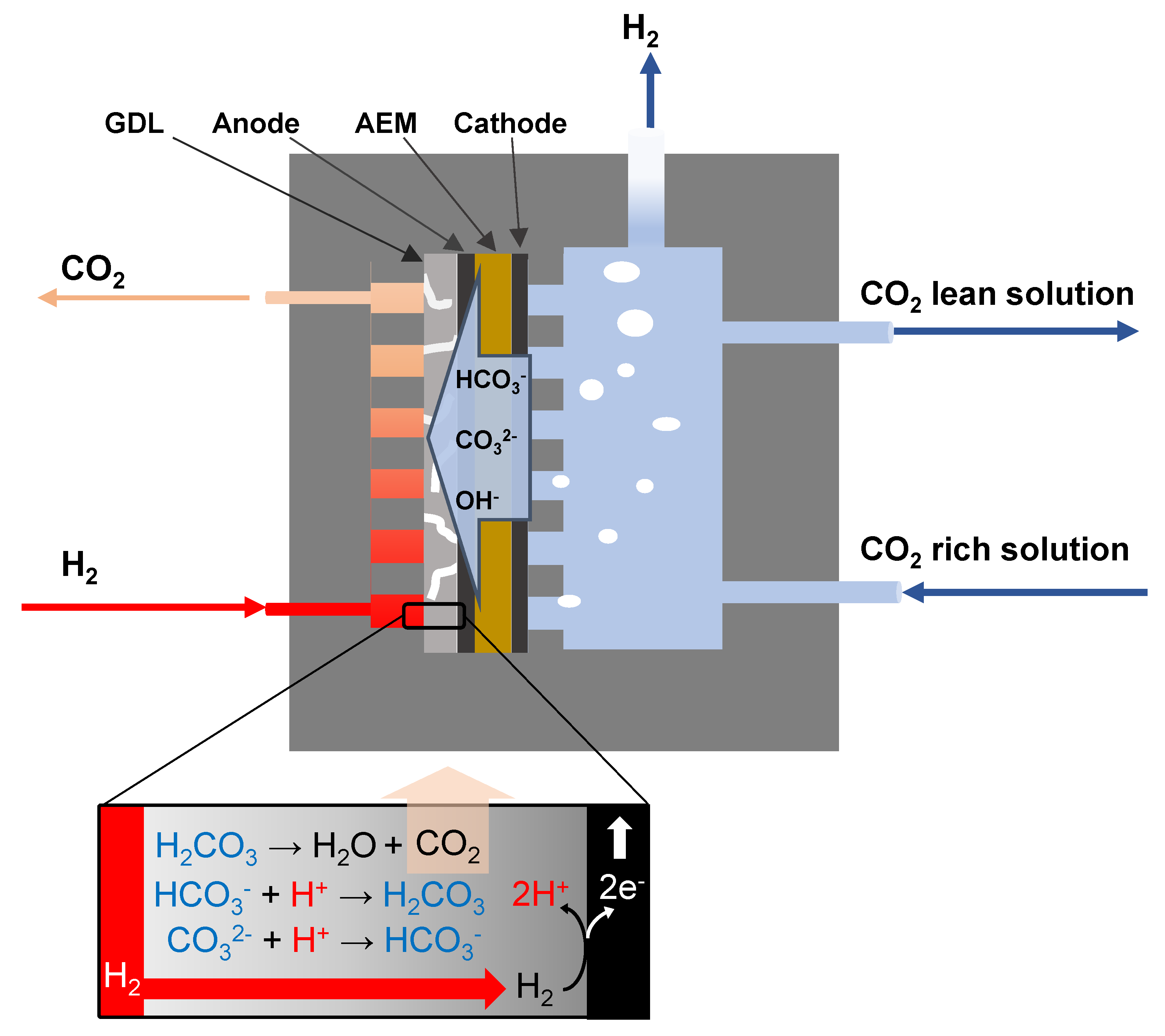
Figure 2.
A comparison of polarisation performance (as a function of (a) anode potential; (b) cathode potential; and (c) cell voltage) between the alkaline water electrolyser and the hybrid cell.
Figure 2.
A comparison of polarisation performance (as a function of (a) anode potential; (b) cathode potential; and (c) cell voltage) between the alkaline water electrolyser and the hybrid cell.

Figure 3.
Anodic polarisation curve obtained at different H2 inflow rates into the anode chamber.

Figure 4.
(a) H2 gas concentration in the permeate side and (b) current density changes of a two-compartment cell due to gas crossover across the AEM (AMI-7001).
Figure 4.
(a) H2 gas concentration in the permeate side and (b) current density changes of a two-compartment cell due to gas crossover across the AEM (AMI-7001).
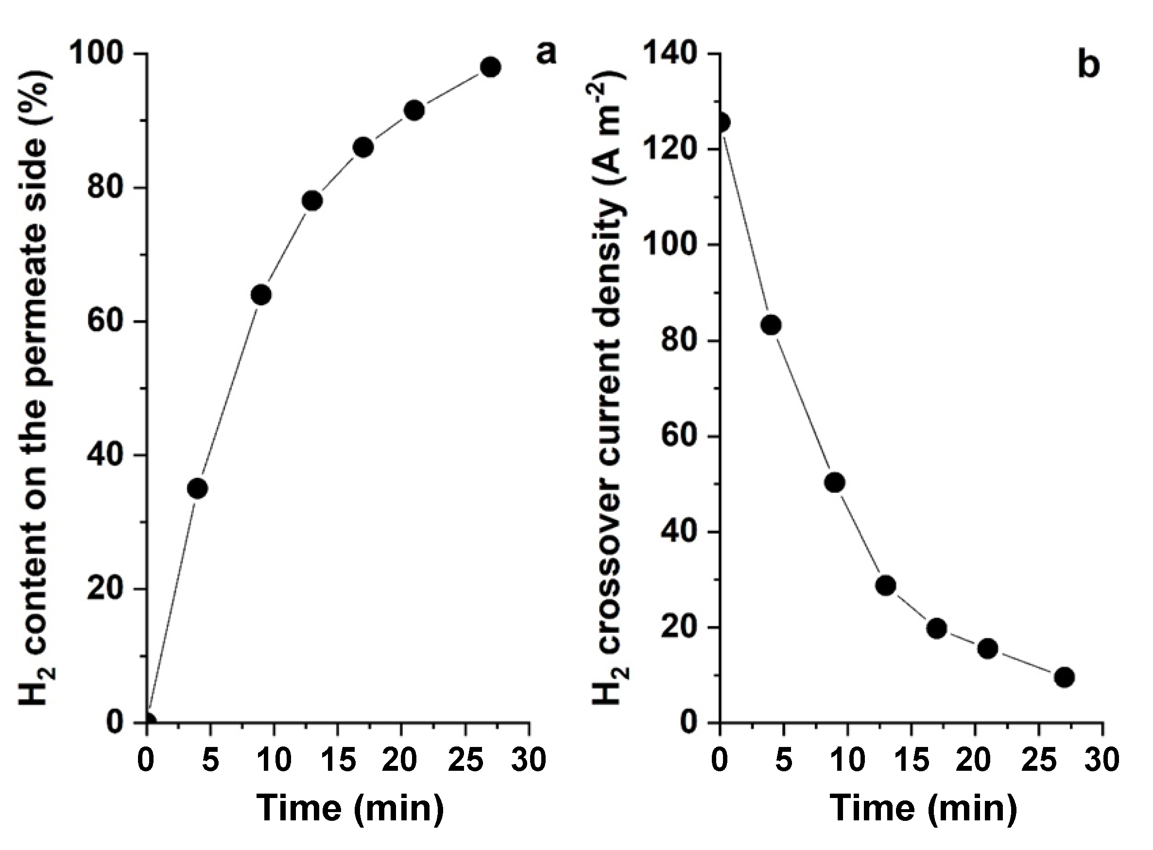
Figure 5.
Effect of current density on current efficiency.

Figure 6.
The CO2 recovery rate from the permeate side (a) and relative diffusional flux, (b) as a function of the applied current density.
Figure 6.
The CO2 recovery rate from the permeate side (a) and relative diffusional flux, (b) as a function of the applied current density.
Disclaimer/Publisher’s Note: The statements, opinions and data contained in all publications are solely those of the individual author(s) and contributor(s) and not of MDPI and/or the editor(s). MDPI and/or the editor(s) disclaim responsibility for any injury to people or property resulting from any ideas, methods, instructions or products referred to in the content. |
© 2024 by the authors. Licensee MDPI, Basel, Switzerland. This article is an open access article distributed under the terms and conditions of the Creative Commons Attribution (CC BY) license (https://creativecommons.org/licenses/by/4.0/).
Share and Cite
MDPI and ACS Style
Mohammadpour, H.; Pivrikas, A.; Cheng, K.Y.; Ho, G. Electrolytic Regeneration of Spent Caustic Soda from CO2 Capture Systems. Processes 2024, 12, 723. https://doi.org/10.3390/pr12040723
AMA Style
Mohammadpour H, Pivrikas A, Cheng KY, Ho G. Electrolytic Regeneration of Spent Caustic Soda from CO2 Capture Systems. Processes. 2024; 12(4):723. https://doi.org/10.3390/pr12040723
Chicago/Turabian StyleMohammadpour, Hossein, Almantas Pivrikas, Ka Yu Cheng, and Goen Ho. 2024. "Electrolytic Regeneration of Spent Caustic Soda from CO2 Capture Systems" Processes 12, no. 4: 723. https://doi.org/10.3390/pr12040723
Note that from the first issue of 2016, this journal uses article numbers instead of page numbers. See further details here.