
Research on the Mechanical Properties and Structural Optimization of Pipe String Joint under Deep Well Fracturing Operation
1
Petroleum Engineering School, Southwest Petroleum University, No. 8, Xindu Avenue, Chengdu 610500, China
2
Exploration Division, PetroChina Southwest Oil and Gas Field Company, No. 12, North Tianfu Avenue, Chengdu 610000, China
*
Author to whom correspondence should be addressed.
Processes 2024, 12(4), 835; https://doi.org/10.3390/pr12040835
Submission received: 6 March 2024
/
Revised: 11 April 2024
/
Accepted: 17 April 2024
/
Published: 20 April 2024
(This article belongs to the Special Issue Risk Assessment and Reliability Engineering of Process Operations)
Abstract
:In order to reduce the failure accidents caused by the insufficient strength of fracturing string joints, theoretical calculation and string design methods were adopted to conduct finite element calculations on commonly used long circular threads. The distribution laws of stress and contact pressure of long round threads were obtained, a non-standard special thread was designed, and a finite element model of the joint of the casing was established. Considering different make-up torques, tensile loads, and tensile torque loads within a certain range, the stress variation law of the special casing threaded joint under this design size was analyzed. Finally, the stress and contact pressure variation law on the threaded tooth was analyzed under different structures, working conditions, and wall thickness parameters. The thread strength and sealing function were compared under various parameters. The results showed that the smaller the wall thickness of the joints, the greater the contact pressure at the threaded tooth. Among them, the contact pressure of the external threaded tooth is too high, and is prone to the sticking phenomenon. The distribution of contact pressure in the middle section is relatively reasonable. Compared with the original structure, the new structure significantly reduces the contact pressure at the head and tail ends of the threaded connection, reducing the risk of sticking.
1. Introduction
In fracturing and well completion operations, it is necessary to frequently place the pipe string in the well hole, and the pipe string must withstand internal and external pressures, which greatly affects the strength of the pipe string and often leads to break or joint fractures. Experts and scholars have conducted extensive research on pipe string design and calculation. Ke Tong et al. [1,2] studied the occurrence of casing leakage accidents during pressure testing in shale gas wells. The influence of internal pressure on defective casing parts was analyzed using the finite element simulation method. The finite element calculation results show that the equivalent stress at the thread defect is lower than the yield strength of the pipe body, and the equivalent stress at the thread defect is much greater than the yield strength of the casing under axial tension and internal pressure. Zhao Lei et al. [3] established a quantitative risk assessment-based safety analysis method for casing strings, revised the deterministic design standards for casing using reliability methods, and developed corresponding reliability design standards. This can reduce the probability of casing damage, predict casing failure behavior in advance, develop reasonable preventive measures, and extend the service life of the casing string. Yuan Ke et al. [4,5,6] pointed out that the deep high-temperature environment has a significant impact on the mechanical behavior of casing, and traditional casing design methods only consider the stress state of the casing at room temperature, which is difficult to adapt to the requirements of deep casing design. Based on the theories of elasticity and thermodynamics, combined with the stress model of casing at room temperature, a calculation model for casing stress under temperature action was established. Penglin Liu et al. [7,8,9,10] conducted shear tests on single-layer casings, flexible double-layer casings, and rigid double-layer casings. In addition, the stress distribution and evolution of the double-layer casing during shear deformation were also studied. C. Santus et al. [11,12] found that the critical stress between the male and female couplings of the oil casing mainly depends on the preload of the shaft pair, and the calculation process takes into account the initial make-up torque and alternating bending load. Yuan GJ et al. conducted a reliability evaluation of pipeline joint threads and conducted experimental research on the stress field of threads during the threading process [13,14]. Feng Chen et al. [15,16] established a three-dimensional finite element model of casing threads based on the principle of virtual work, nonlinear contact theory, and elastic–plastic yield criterion. The method of considering frictional shear stress during assembly was used, and the stress distribution law of connecting threads during assembly was obtained. This study provides theoretical guidance for the correct operation of thread threading process. A. R. Shahani et al. [17,18] established a two-dimensional symmetrical structure of casing, tubing, and casing threads based on API standards [19], and analyzed the causes of failure of casing, tubing, and casing threads. Yosuke Oku et al. [20,21,22,23] conducted fatigue tests on petroleum pipe threads and found that the main factors affecting the fatigue strength of threaded specimens are tool wear and cutting speed, while the influence of cutting method and radial feed is relatively small.
The stress and strain distribution of the double shoulder casing joint under torque, compression force, tensile load, and bending moment were analyzed, and the mechanical performance parameters of the double shoulder casing joint under these loads were obtained. This article uses the finite element method and theoretical calculations to conduct structural optimization analysis on pipe string joints, develops a high-strength non-standard special threaded structure, and conducts finite element calculation based on actual working conditions. The results show that this special threaded buckle greatly improves the bearing capacity of the pipe string. Finally, the designed threaded structure is processed and applied on site.
2. Mechanics Principles of Casing Joint Analysis
Due to their dense formation, fracturing cannot form channels in joints (Baosteel, Shanghai in China). Repeated squeezing or acid pushing exceeding the pressure limit can cause rapid expansion and contraction of the casing, as well as repeated bending. After testing, it may cause the upper free section to trip or break. The on-site photo of a casing rupture is shown in Figure 1.
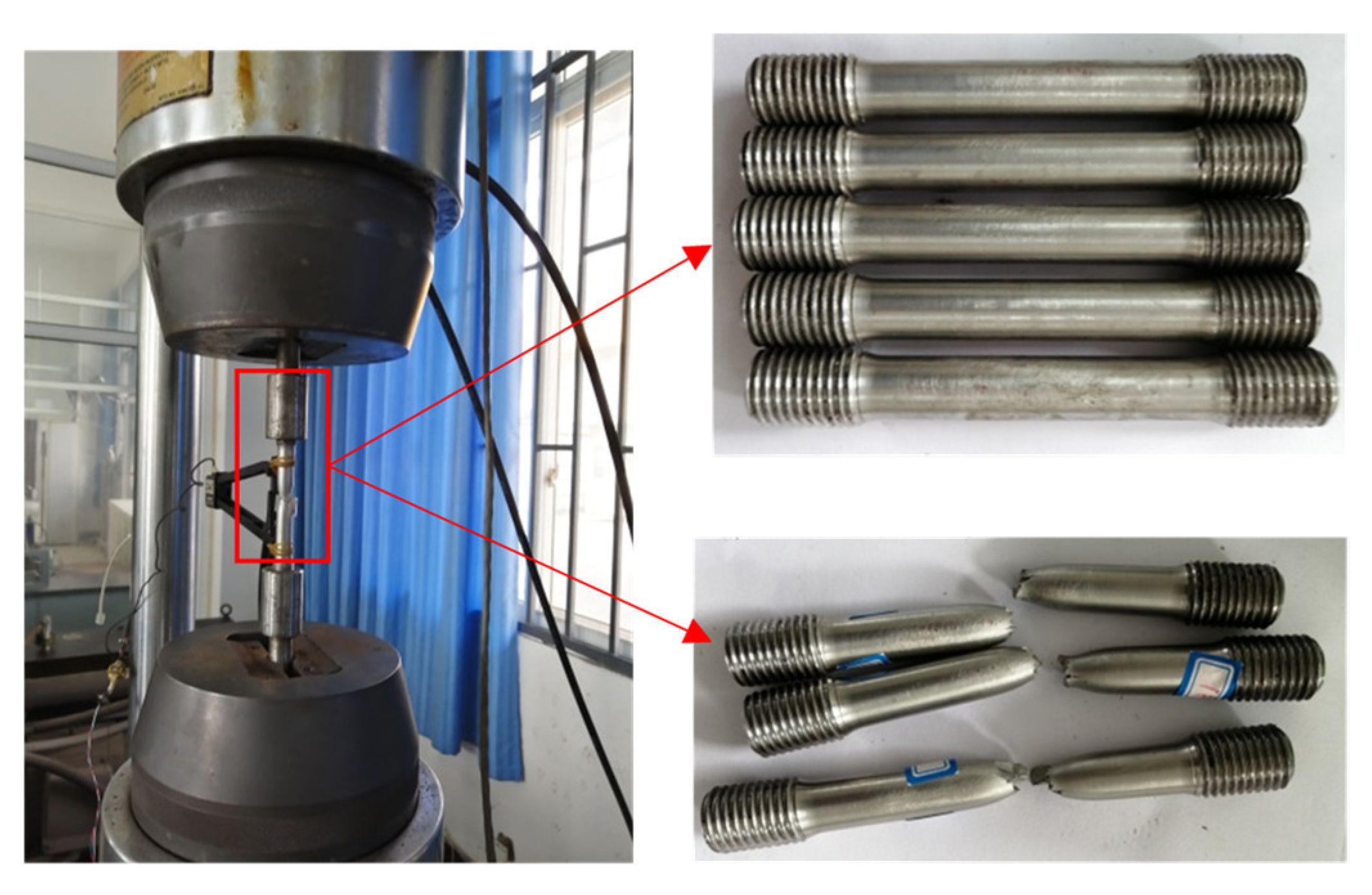
The pipe string at the horizontal well has a high frictional resistance, long horizontal wellbore section, and small annular space gap. During the process of downing the pipe string, the casing is frequently lifted and released, the number of casing movements is high, and the down time is long when the last few casings are downed, causing casing fatigue and fracture, as shown in Figure 2.
Therefore, in order to avoid thread failure accidents caused by the insufficient strength of the fracturing pipe string joints, an improved design study was conducted on the existing long circular pipe string joints. Finally, a special threaded buckle was designed for the pipe string, with an internal thread (also known as a “box”) set at the lower end, mainly for hanging a 400 t pipe string at the lower end. During the process of downing the pipe string, it is necessary to verify the rationality of selecting the box end through verification under the action of the thread up torque, tensile load, internal and external pressure, and bending moment. Before the pipe string is downed into the well, it is necessary to control the torque of the pipe joint to ensure that the pipe string can meet the hanging load and sealing performance for a long time.
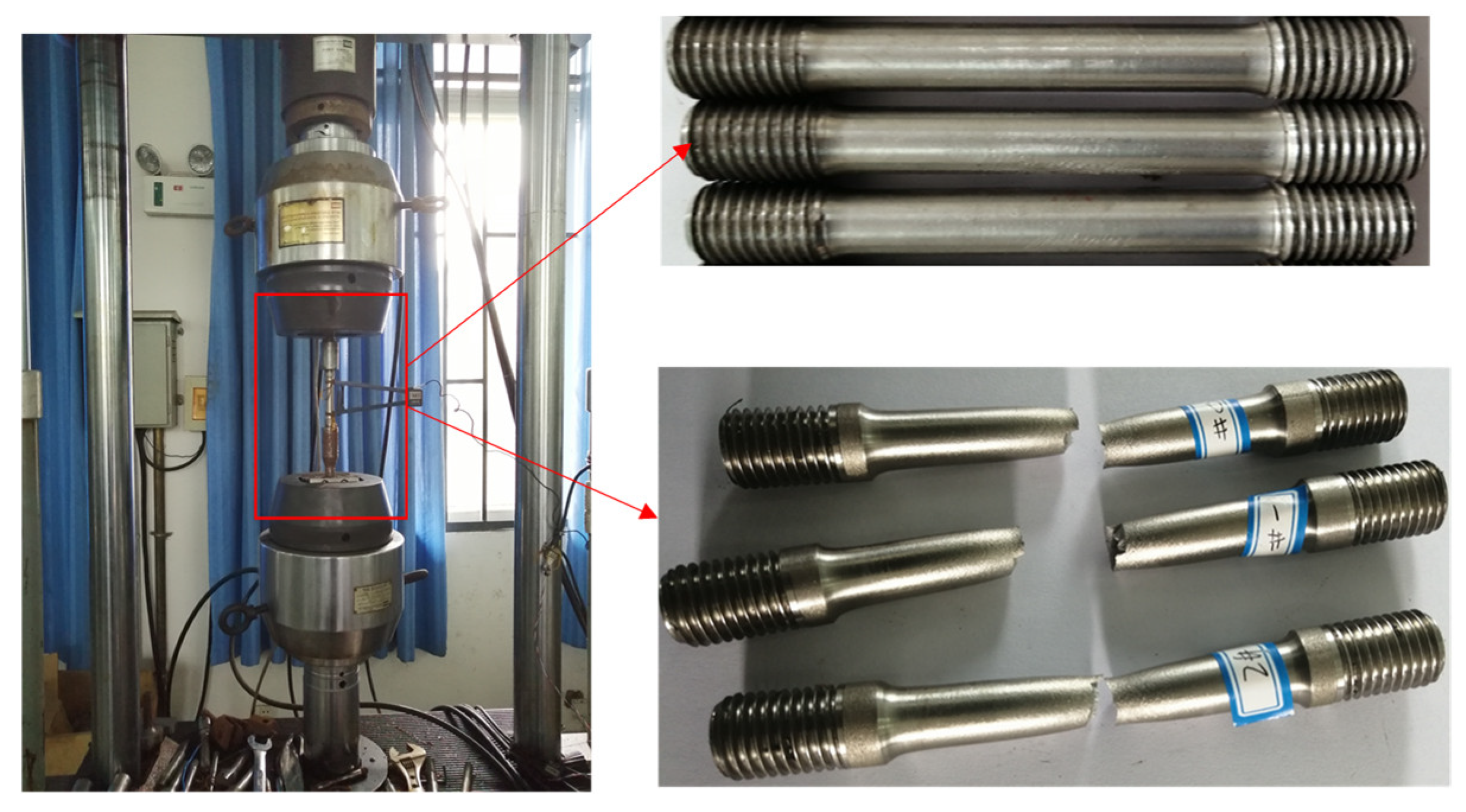
In order to obtain casing strength and finite element calculation data, this section conducted tensile tests on P110 materials. The sample is a φ12.7 mm round steel. P110 materials are isotropic elastic–plastic materials. Three sets of specimens of this material were subjected to tensile tests, and the tensile fracture deformation diagram of the material was obtained, as shown in Figure 3.
The stress–strain relationship between the materials is shown in Figure 4. From the experimental curve, it was found that P110 has good toughness, with elongation rates close to or exceeding 20%.
Table 1 shows the tensile test data of P110. The average yield strength of P110 is 676.7 MPa. The tensile strength is 770.0 MPa.
3. Stress Analysis of Casing Threads
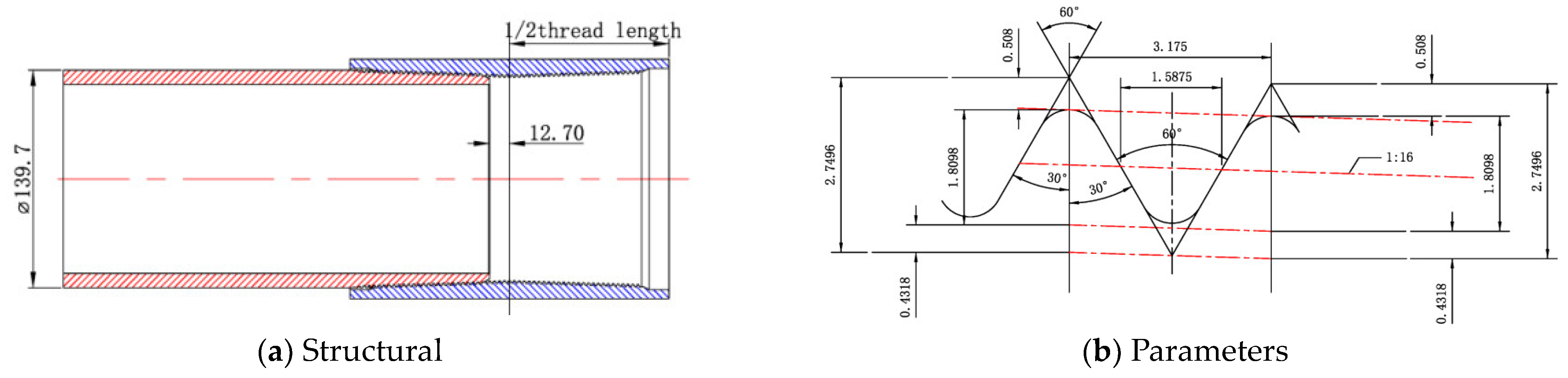
Based on the casing string used in the fracturing process, the parameters of the 5.5 inch API casing long circular thread and the structure of the pin and box joints were obtained from the manual. Figure 5a shows the structure of the casing round thread joint, and Figure 5b shows the specific parameters of the long round thread.
We established a finite element model of the 5.5 inch long round thread of the casing and studied the joint threads of the casing under the working conditions of torque T, axial tension and compression F, internal fracturing pressure P, and bending moment M, as shown in Figure 6b. In the finite element calculations, the three-dimensional modeling of threads simplifies the complex parts of thread segments, and the two-dimensional symmetric thread structure is the actual model. The two-dimensional threaded joint can apply interference equivalent to applying corresponding torque, and its main principle is to gradually remove the interference nodes on the thread surface in the tangential and normal directions through interference adjustment. The penalty function method with a friction coefficient of 0.05 is used, and the normal behavior defines the pressure interference of hard contact and allows separation after contact. Under the action of torque and external load, due to the elastic–plastic deformation of the sealing surface and thread of the threaded joint, and the displacement of the contact surface, geometric nonlinearity and material nonlinearity need to be enabled in ABAQUS V6.0 software. The overall model adopts C3D8I elements, and mesh refinement is applied to the threads and sealing surfaces, respectively. To accelerate the solving speed of the nonlinear analysis and to ensure the accuracy of calculation, the ABAQUS V6.0/Standard solver is selected for solving analysis.
With TP125 grade steel (minimum yield strength 862 MPa), the outer diameter of the casing is 5.5 inches, and the wall thickness are 9.17 mm and 10.54 mm; this establishes a three-dimensional structure of the API long circular threaded joint. We set the boundary condition type to “displacement-angle”, limit the degrees of freedom of the structure in the direction perpendicular to the y-axis, fix the end face of the box, convert the axial force into a uniform load, and apply it to the large end of the pin. The pin and box surfaces are hand-tightened to the machine tight state joint, forming interference fit, and the axial force F during the casing lowering or fracturing process is applied to the machine tight state joint. F is 0~100 t of tensile force and 0~100 t of compressive force. The bending stress M of the casing is applied to the machine tight state joint, and M is 0~100 MPa in the axial direction. The internal pressures P and P are 0~100 MPa during the casing fracturing process at the machine tight state joint.
3.1. Calculation Results of Joints under Torque Conditions
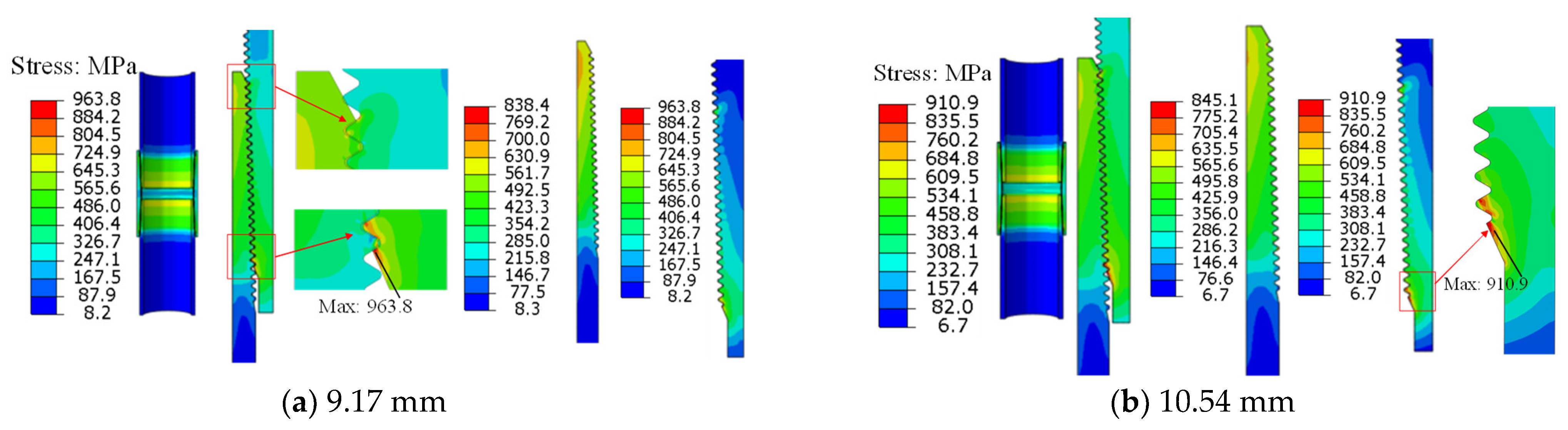
The pin and box joints rotate three times from hand tight to machine tight, resulting in interference on the tooth surface. As shown in Figure 7a, the maximum stress value of the lower thread is 838.4 MPa, and the stress at the head and tail connections is relatively high. The overall stress value does not exceed the material yield limit. There is stress concentration at the head and tail connections of the box, with a maximum stress value of 963.8 MPa. It enters the plastic stage and damage occurs, while the stress values at other positions are relatively low. As shown in Figure 7b, the overall stress of the 10.54 mm wall thickness joint has decreased, and the stress distribution is similar to that of the 9.17 mm joint. The maximum stress of the lower half of the joint occurs at the same location, with a maximum stress value of 910.9 MPa, which is not significantly reduced. It exceeds the material yield limit, creating a dangerous interface and causing damage.
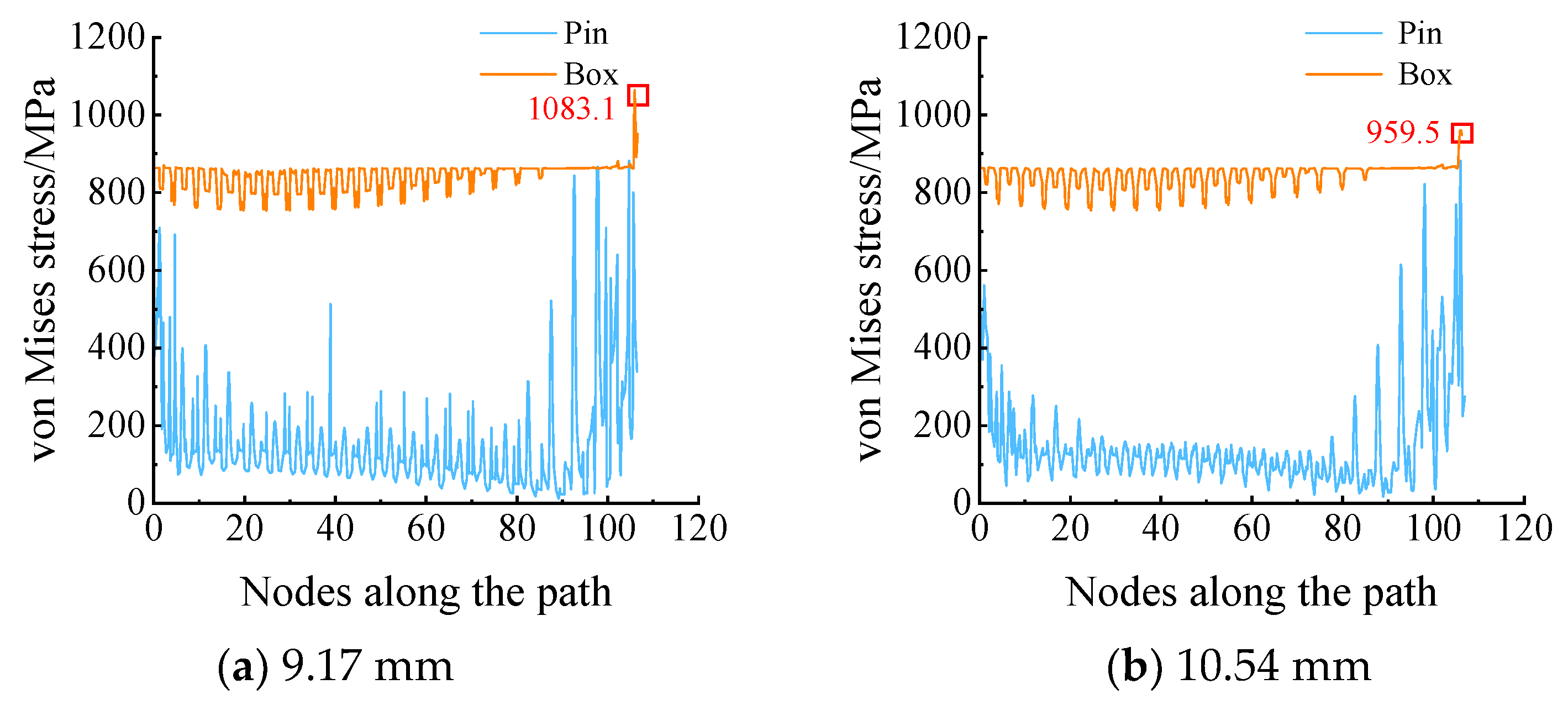
Figure 8 shows the stress variation curve along the thread contact path. Under the same working conditions, the stress distribution in the middle section of the threaded connection of the two types of joints is similar. The stress at the head and tail connections is relatively high, and stress concentration occurs at the first threaded tooth at the small end of the box.
3.2. Calculation Results of Joints under Axial Tension Conditions
As shown in Figure 9a, the maximum stress values at the first and last buckles in the lower half of the joint are 881.9 MPa and 879.7 MPa, respectively. At the same time, the stress at the large end of the lower of pin exceeds the yield strength of the material. As shown in Figure 9b, the maximum stress values are 868.3 MPa and 876.9 MPa, respectively. Increasing the wall thickness of the courseware can reduce the stress on the thread teeth, but the effect is not satisfactory.
3.3. Calculation Results of Axial Compression Joint
The maximum stress is 999 MPa, which occurs at the small end port of the lower half of the coupling when in the machine tightened state, and the axial compression is 100 t, as shown in Figure 10a. Figure 10b shows the stress variation curve along the thread contact path. Under the same working conditions, the overall stress of pin with a larger wall thickness decreases, and the overall stress value of the box increases. However, the stress difference between the top and bottom of the tooth decreases, and the distribution is more uniform, indicating better compression resistance.
3.4. Calculation Results of Joints under Internal Pressure Conditions
When an internal pressure of 100 MPa is applied in the machine tightened state, the stress on the casing body significantly increases, and the stress on the top and bottom of the mating teeth of the pin increases, with more parts entering plasticity. Only a few thread teeth of the pin and box show significant stress in Figure 11, and the stress on the pin section is far less than the yield limit of the material. The stress distribution on the box thread is relatively uniform and does not exceed its yield limit, which shows that the thread has a good internal pressure resistance performance.
3.5. Calculation Results of Joints under Bending Stress Conditions
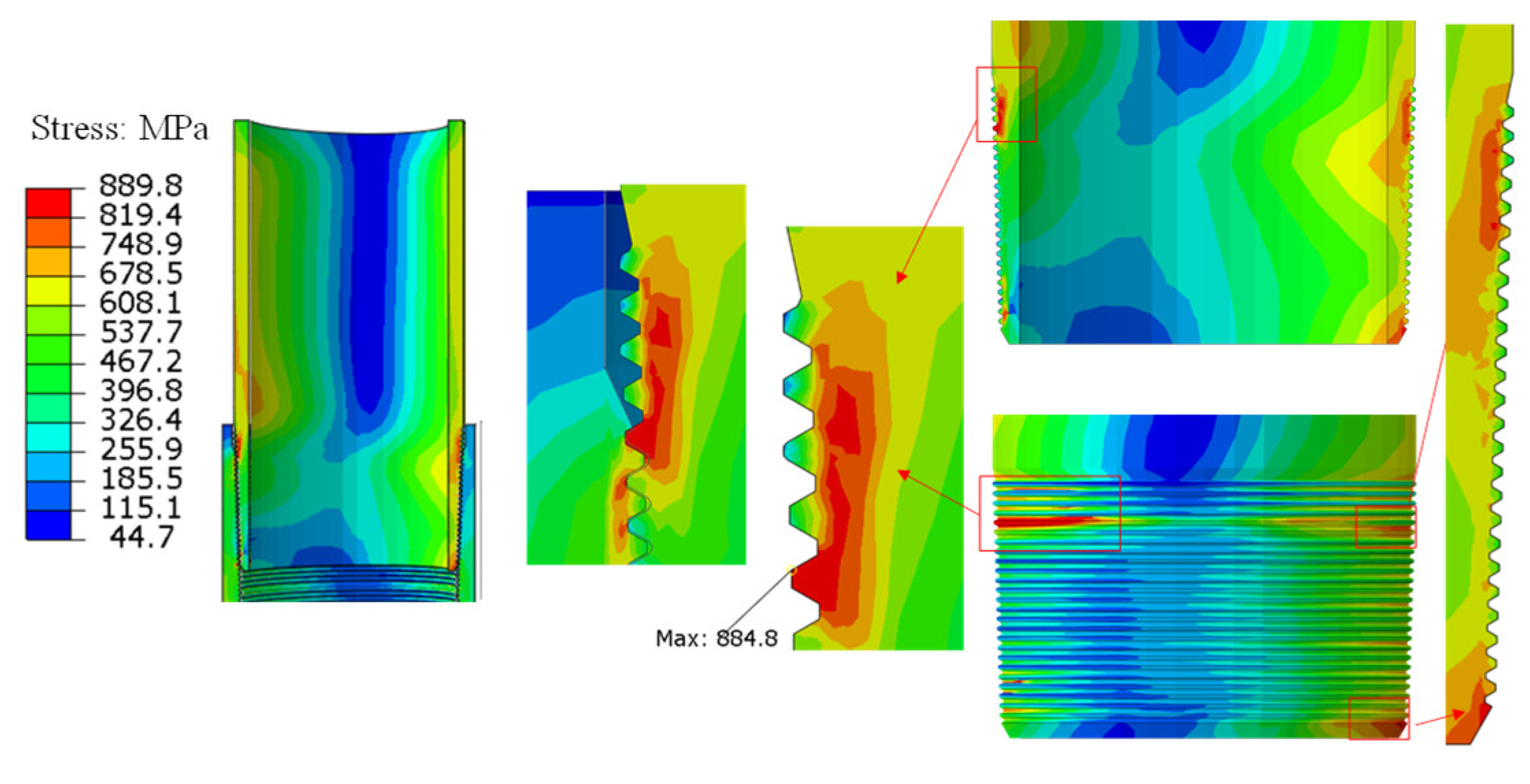
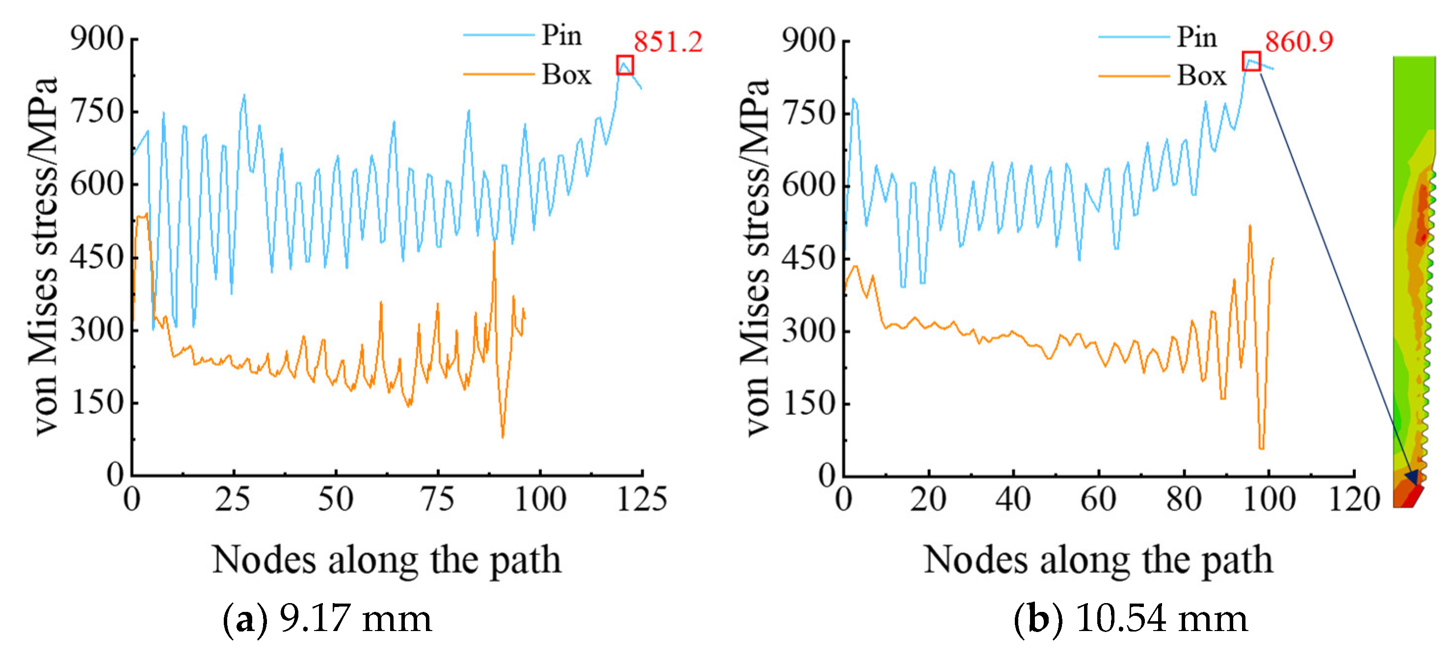
Applying a bending stress of 75 MPa in the machine tightened state, the pin and box deviate severely, and the stress on the compression and tension sides of the pin increases. There is a large area of stress concentration at the compression side of the pin, with a maximum stress value of 884.8 MPa, as shown in Figure 12. The bending effect leads to an increase in stress on the front teeth of the male buckle thread, resulting in stress concentration at the large end of the male buckle. The stress at both the large and small ends of the tensile side exceeds the material yield limit, and the maximum stress value reaches 851.2 MPa, as shown in Figure 13.
As shown in Figure 14, the stress distribution at the top and bottom of each tooth is more uniform, all of which are far below its yield limit. This indicates that the joint with an increased 10.54 mm wall thickness has stronger internal pressure resistance.
4. Research on Improvement of Thread Structure for Connection of Pipe String
The lower end of the casing mainly uses a pin as the connecting end, but it often experiences tensile or sliding damage during on-site use. Therefore, in order to improve the insufficient strength of the connecting thread at the lower end of the casing, an improved design study was conducted on the existing thread. A special thread was selected, and the improved thread and pipe body were subjected to strength verification, such as torque and tensile load, laying a theoretical foundation for the structural design of the casing threaded end.
4.1. Theoretical Study on the Torque of Special Thread Upsetting
The previous literature mainly focused on the symmetric modeling of threads, which can achieve load analysis under tensile load and internal and external pressure load strength. For two-dimensional symmetric models, torque loading is not performed, and the thread stress and strength cannot be calculated accurately. The von Mises stress variation law of the special joint was analyzed under the combined load of different make-up torques, tensile loads, and tensile torques within a certain range in this section, and we determined whether the bearing capacity of the special thread met the requirements for casing use. The lower part of the casing developed in this article is connected to a 5.5-inch casing (with an outer diameter of 139.7 mm and wall thicknesses of 9.17 mm and 10.54 mm), as shown in Figure 15.
API 6A has specified the use of 718 precipitation-reinforced nickel based alloy as casing materials. The yield strength of the 718 material steel grades can reach (140–150) ksi, which is (964.5–1033.5) MPa. According to the API casing column strength calculation formula, the strength of the casing in Figure 14 is calculated as shown in Table 2. When the wall thickness is 9.17 mm, its extrusion strength is (89.35–92.91) MPa. When the wall thickness is 10.54 mm, its tensile strength is (120.57–126.75) MPa, meeting the required annular experimental pressure of 100 MPa.
In order to reduce the risk of failure of the main parts of the hanger, in addition to the structural design, it is also necessary to carry out strict material selection and material mechanical property tests. The alloy, namely 718, (3Cr2NiMo) is selected as the material of the mandrel structure, and the tensile test of this material is carried out to provide test data for finite element calculation. Figure 16 is the photos of samples before and after tensile test of 718.
The stress–strain relationship between the materials is shown in Figure 17. From the experimental curve, it was found that 718 has good toughness, and according to the stress–strain results in Figure 17, the yield strength of the 718 material is about 1000 MPa, and the tensile strength is about 1260 MPa.
4.2. Thread Interference Contact Friction Torque
To increase the strength of the thread of the casing string, the interference fit is required between the special threads of the casing string. The tooth side interference refers to the reduction in the gap between the inner and outer thread tips and roots, and the radial interference contact between the bearing surface and the guide surface, as shown in Figure 18.
If the thread end is taken as the coordinate origin, the radius of the tooth top tooth root contact surface can be expressed a follows:
In the formula, is the thread pitch diameter, mm; is the full thread working height, mm; is the axis length coordinate of thread, mm; is the incomplete thread length, mm; is the full thread length, mm. Thus, the torque generated by thread interference can be obtained by integrating along all contact lines of ΣMN, as follows:
In the formula, is the width of the trapezoidal thread base, mm; is the friction coefficient of threaded surface, dimensionless; is the thread interference torque coefficient, N · m/mm.
4.3. Torque on the Main Sealing Surface
Due to the taper of the main sealing surface, the contact pressure of the sealing surface will generate an axial preload force. For cone-to-cone sealing structures, the actual contact line of the sealing surface is PQ, as shown in Figure 19.
As shown in Figure 19, the contact radius of the contact surface between the cone and the main sealing structure of the cone is as follows:
In the formula, is the radius of the sealing surface nose end, mm; is the coordinate of the position of the conical sealing structure on the conical surface, mm; I the axial length of sealing surface, mm.
The axial preload generated by the sealing surface can be obtained by integrating along PQ, as follows:
In the formula, is the axial preload force, N. Therefore, the thread torque generated by the main sealing surface can be calculated by the Farr formula, as follows:
In the formula, is the thread torque, N · m; is the equivalent force arm, mm; is the bearing surface angle, °.
The friction torque of the main sealing surface can also be obtained by integrating along PQ, as follows:
In the formula, is the friction torque, N · m; is the friction coefficient. The total torque of the main sealing surface that can be obtained is as follows:
4.4. Torque on the Shoulder Surface
The actual contact line of the shoulder surface is RS in Figure 19. If the stress on the shoulder is uniformly distributed, the axial preload force on the shoulder is as follows:
In the formula, is the axial preload force generated by the shoulder surface, N; is the shoulder pre-tightening contact pressure, MPa; is the shoulder chamfer, degrees; , are the inner and outer radii of the shoulder are in millimeters.
Similarly, the thread torque generated by the shoulder surface can be calculated using the Farr formula, and the total torque acting on the shoulder surface is as follows:
In the formula, is the torque of the shoulder surface thread, N · m; is the friction torque, N · m; is the friction coefficient of the shoulder surface. The approximate relationship between the axial preload force on the shoulder surface and the designed axial interference fit of the shoulder is as follows:
In the formula, is the axial interference fit of the shoulder, mm; is the average radius, mm; is the axial length of cone, mm.
5. Research on Improvement of Thread Structure of Pipe String
5.1. Establishment of Finite Element Model for Special Threads
The special trapezoidal thread selected for the casing thread structure can withstand complex working conditions, such as tension, compression, bending, internal and external pressure, and high temperature underground for a long time. The thread profile of the special casing is a trapezoidal thread profile, with a bearing surface angle of 3° and a guide surface angle of 10°. As shown in Figure 20, the thread taper is 1:16, with five teeth per inch. The sealing surface taper is 1:2, and the shoulder angle is 15°. This section establishes a special type of threaded joint with a diameter of 139.7 mm × 9.17 mm (or 10.54 mm), as shown in Figure 21a. The finite element model of special thread was established as shown in Figure 21b. The external thread is divided into 12,541 elements, and the internal thread is divided into 11,452 elements. The material used for the casing joint is 718 high-performance steel. The yield strength of the material is 1020 MPa, the tensile strength is 1106 MPa, its elastic modulus E is 206 GPa, and the Poisson’s ratio is 0.3.
During the calculation process, fixed constraints are applied to the bottom end face of the box, and the end face of pin is coupled with the reference point. By applying tension, internal pressure, torsion, and their composite loads at this coupling point, and the remaining surfaces are free boundary conditions.
5.2. Two Types of Wall Thickness Pins under Torque Working Conditions
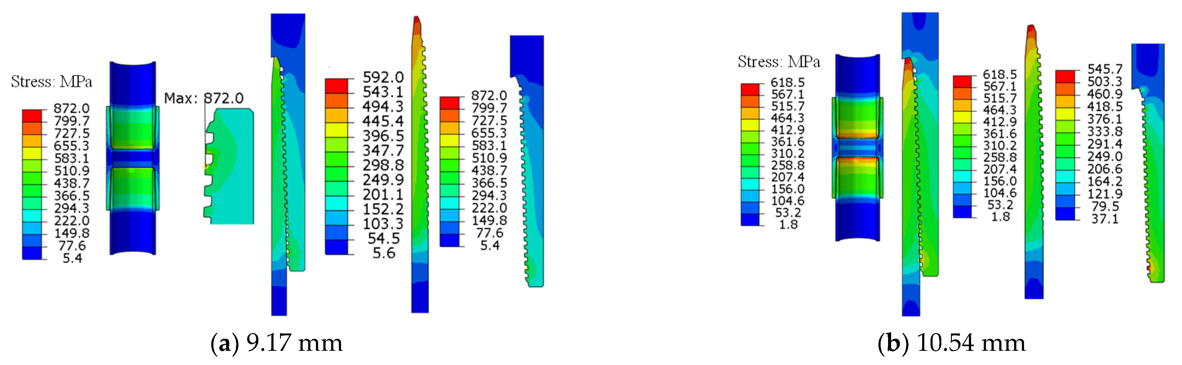
The pin and box joints rotate three times from hand tight to machine tight, resulting in interference on the tooth surface. As shown in Figure 22a, the maximum stress value of the lower tooth is 838.4 MPa, and the stress at the head and tail connections is relatively high. The overall stress value does not exceed the material yield limit. There is stress concentration at the head and tail connections of the box, with a maximum stress value of 963.8 MPa. As shown in Figure 22b, the overall stress of the 10.54 mm joint is lower, and the maximum stress at the small end of the pin occurs at the same position as the 9.17 mm joint, with a maximum stress value of 618.5 MPa and a maximum stress value of 545.7 MPa for the female buckle, which is within the safe range.
5.3. Calculation Results of New Joints under Axial Tension Conditions
Under axial tension of 100 t in the machine tightened state, the overall stress of the new trapezoidal thread joint is significantly reduced, with a maximum stress value of 609 MPa, which does not exceed the material yield limit. The overall stress is lower, and the strength is higher than that of the 9.17 mm joint. From the stress variation curve on the contact path, it can be seen that under the same working conditions, as shown in Figure 23a, the stress distribution of the two types of wall thicknesses of the pin and box is lower. For the 10.54 mm joint, stress concentration occurs at the tooth tip of the pin’s large end, with a maximum stress value of 609.2 MPa, but it does not exceed the yield limit of the material, as shown in Figure 23b. Obviously, the tensile resistance of the new structure has been improved.
5.4. Calculation Results of New Joints under Axial Compression Conditions
As shown in Figure 24a, under axial compression of 100 t in the machine tightened state, the overall stress level is relatively low, and the maximum local stress value is 866.6 MPa. As shown in Figure 24b, the maximum stress occurrence position of the 10.54 mm joint is the same as that of the 9.17 mm joint, with a maximum stress value of 745.3 MPa, which is within the safe range.
5.5. Calculation Results of New Joints under Internal Pressure Conditions
As shown in Figure 25a, the stress of the coupling and casing body is significantly reduced under an internal pressure of 100 MPa. The overall stress value of the lower half of the coupling does not exceed the yield limit of the material, and the stress in the nonbearing section of the pin is relatively high under the action of internal pressure. As shown in Figure 25b, the overall stress values of the lower pin and lower half coupling do not exceed the yield limit of the material, and the stress in the nonbearing section of the pin is relatively high under internal pressure.
5.6. Calculation Results of New Joints under Bending Stress Conditions
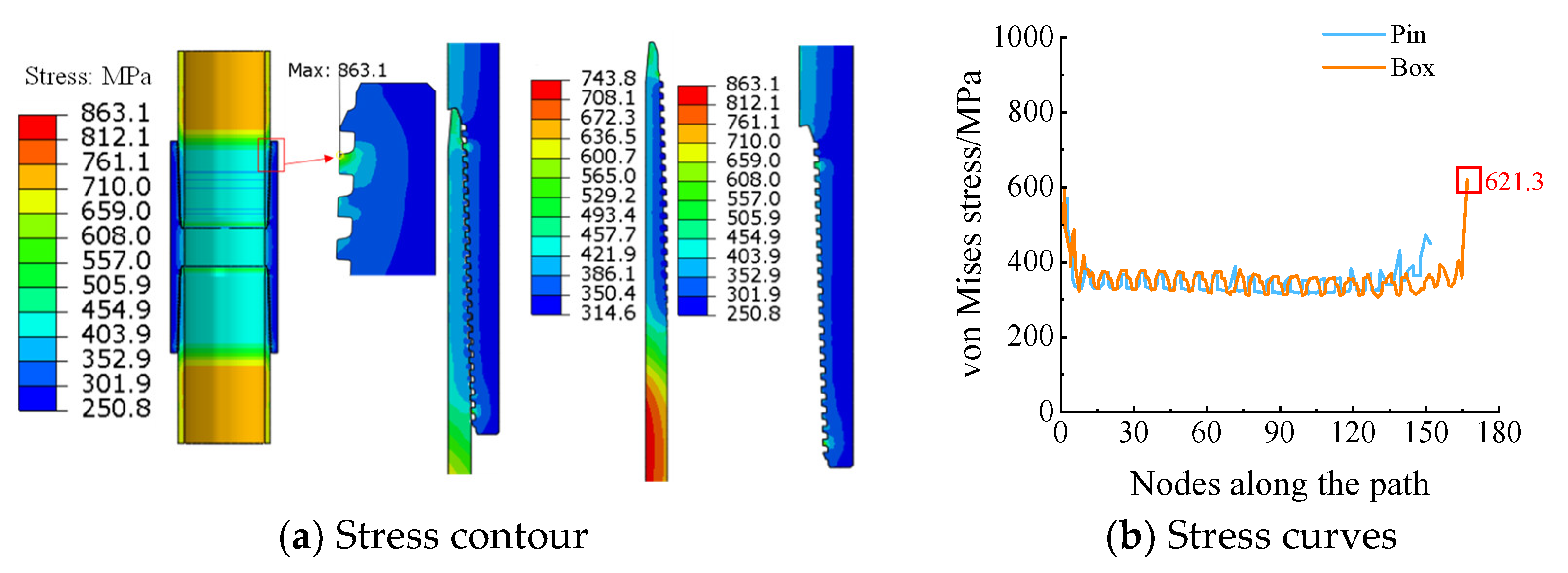
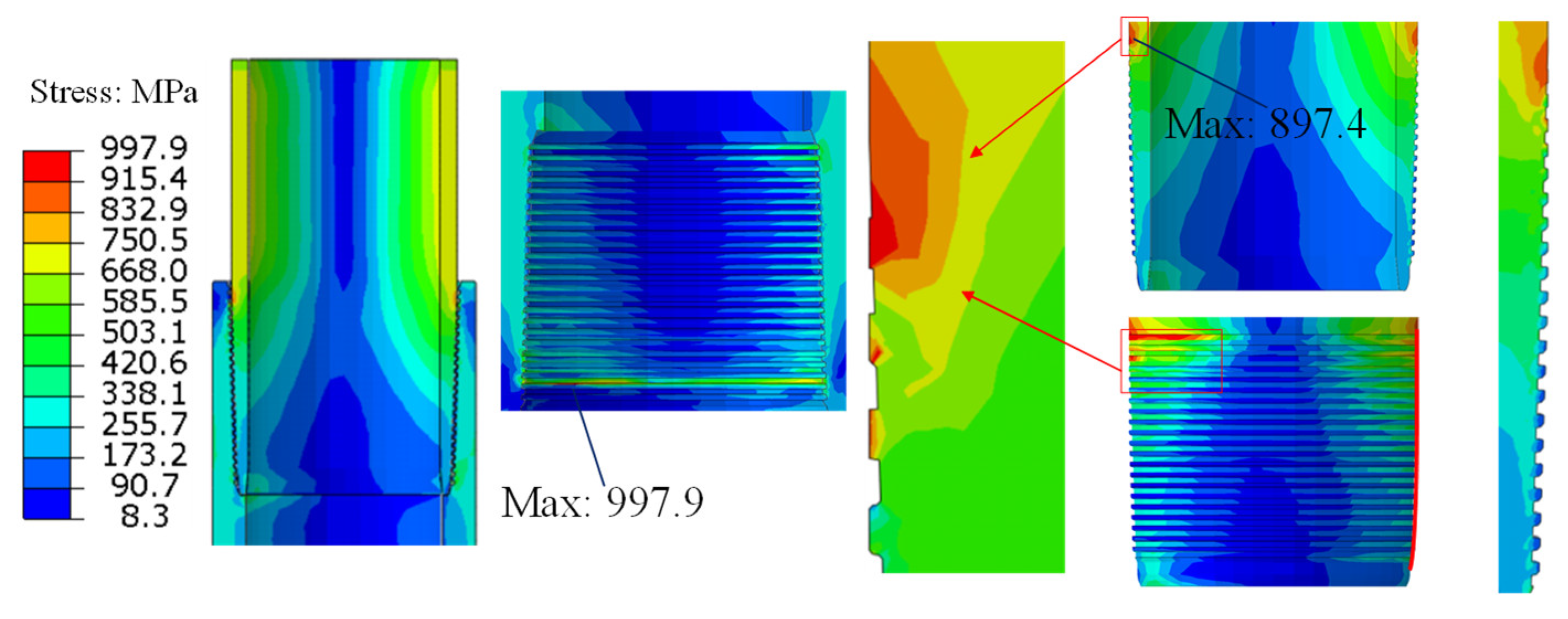
As shown in Figure 26, the deflection of the pin and box is obvious, and the stress on the compression and tension sides of the pin is relatively large under a bending stress of 75 MPa. The stress concentration appears at the bottom of the first three teeth of the compression side of the pin, with a maximum stress value of 975.4 MPa. The bending effect causes the stress on the first teeth of the pin to gradually increase. The maximum stress of the joint occurs at the last teeth on the tensile side of the box, with a maximum stress value of 1036.6 MPa. The stress at other positions is within the safe range.
As shown in Figure 27, stress concentration occurred on both the compression and tension sides of the tooth, with a maximum stress value of 897.4 MPa on the compression side. The stress concentration on both sides entered the plastic stage and damage occurred, while the stress distribution in other positions was reasonable. The maximum stress value of the box occurs at the bottom of the last thread tooth, with a maximum stress value of 997.9 MPa, which has exceeded the material yield limit.
Figure 28 shows that the stress values of the two types of joints do not exceed 800 MPa. The stress concentration appears on the first tooth of the tension side of the pin, and the maximum stress value can be found to be 898.1 MPa from the stress change curve of the contact path. From the stress change curve of the contact path, it can be inferred that the maximum stress value on the tension side is 864.8 MPa.
Figure 29 shows that the maximum contact pressure on the tensile side of the 9.17 mm joint occurs at the first thread, with a maximum contact pressure value of 1350 MPa, which is prone to sticking. The maximum contact pressure on the tensile side of the 10.54 mm joint is 947.3 MPa, which is improved compared to the 9.17 mm joint.
6. Analysis of Joint Sealing Performance under Different Working Conditions
6.1. Comparative Analysis of Mechanical Properties of Joints with Different Wall Thicknesses
Through the above comparative calculation and analysis, the maximum stress and contact pressure corresponding to various working conditions with two different wall thickness joints are obtained, as shown in Table 3 and Table 4. Under working conditions of torsion, axial tension, axial compression, and internal pressure during fracturing, the maximum stress and contact pressure of the new structure are lower than those of the original structure. Under the condition of applying bending stress, the maximum stress and contact pressure of the new structure slightly increase, but the overall stress distribution of the joint is more uniform. For the joint with wall thickness of 9.17 mm, internal pressure has a significant impact on the stress of the original structure, torque has a significant impact on the contact pressure of the original structure thread, bending moment has the greatest impact on the stress of the new structure, and bending moment has a significant impact on the stress and contact pressure of the new structure. For the joint with a wall thickness of 10.54 mm, internal pressure has a significant impact on the stress and contact pressure of the original structure, bending moment has the greatest impact on the thread stress of the new structure, and torque has a significant impact on the contact pressure of the new structure.
In addition, the average stress in the middle section of the pin is less than 600 MPa. Except for the larger contact pressure at the first tooth, the contact pressure distribution at other positions is reasonable and has a good auxiliary sealing effect.
6.2. Comparative Analysis of Sealing Performance under Conventional Working Conditions
The trapezoidal joint adds a shoulder auxiliary sealing structure on the basis of the long round joint, as shown in Table 5. The maximum contact pressure of the pin of the trapezoidal joint is greater than the pin of the long round joint under axial compression and internal pressure conditions, and the maximum contact pressure of the pin of the trapezoidal joint is slightly higher than the pin of the long round joint under tensile conditions. At the same time, the maximum contact pressure of the box of the trapezoidal joint is significantly reduced compared to the box of the long round joint under three working conditions, reducing the risk of joint sticking. Under internal pressure conditions, the contact pressure of the trapezoidal joint is significantly reduced.
As shown in Figure 30a, the distribution pattern of contact pressure for the long round joint during axial tension and compression is similar. The contact pressure is relatively high at the large end. The maximum contact pressure value during axial tension is 2008.1 MPa, which appears on the bearing surface of the last button of the lower pin and the box. The maximum contact pressure value under axial compression is 1729.9 MPa, which appears at the last tooth of the upper pin and the box meshing. The contact pressure on the bearing surface of the middle thread section is significantly greater than that of the guide surface. As shown in Figure 30b, the effect of axial tension causes the non-full top conical surface of the pin to closely fit with conical surface teeth of the box when the eccentric trapezoidal joint is axially stretched on the pin, resulting in a smaller contact area and a larger contact pressure. The maximum contact pressure reaches 2208.8 MPa, and the same situation occurs at the corresponding position of the lower tooth. The contact pressure distribution in the middle thread section is reasonable. A new shoulder auxiliary seal has been added to the trapezoidal joint. The contact surface between the small end of the pin and the large end of the box tightly adheres when the thread joint is subjected to axial compression load. The contact pressure value at the contact point between the small end of the pin and the shoulder of the box has been increased to 1444.1 MPa, playing a role in auxiliary sealing.
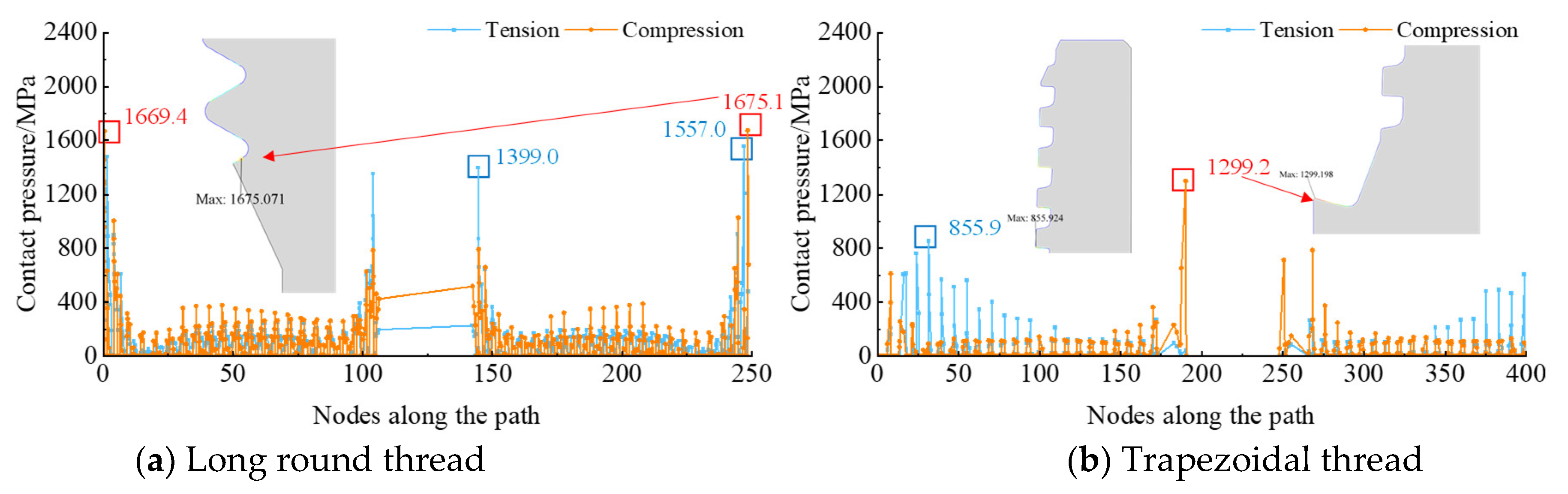
As shown in Figure 31a, the contact pressure distribution of the box of the long round joint is basically the same as that of the pin. The contact pressure at the small end of the lower half coupling of the box decreases by about 500 MPa under the axial tension condition, while the contact pressure at other positions remains basically unchanged. Under the axial compression condition, there is a large contact pressure at the large end, and the maximum contact pressure values at the upper and lower male coupling ends are not significantly different. The long round thread not only needs to play a connecting role but also ensures sealing performance. As shown in Figure 31b, the box of the trapezoidal joint has a larger contact area at the position under tensile conditions where the maximum contact pressure occurs on the box, resulting in a lower contact pressure value. Compared with the long round joint, the trapezoidal joint tries to increase the contact pressure as much as possible to enhance the auxiliary sealing performance while avoiding sticking. Due to the sealing shoulder function of the trapezoidal joint, the contact pressure at the position corresponding to the maximum contact pressure of the pin and the box is increased to 1299.2 MPa. The increase in contact pressure can ensure good sealing effect.
6.3. Comparative Analysis of Sealing Performance under Bending Conditions
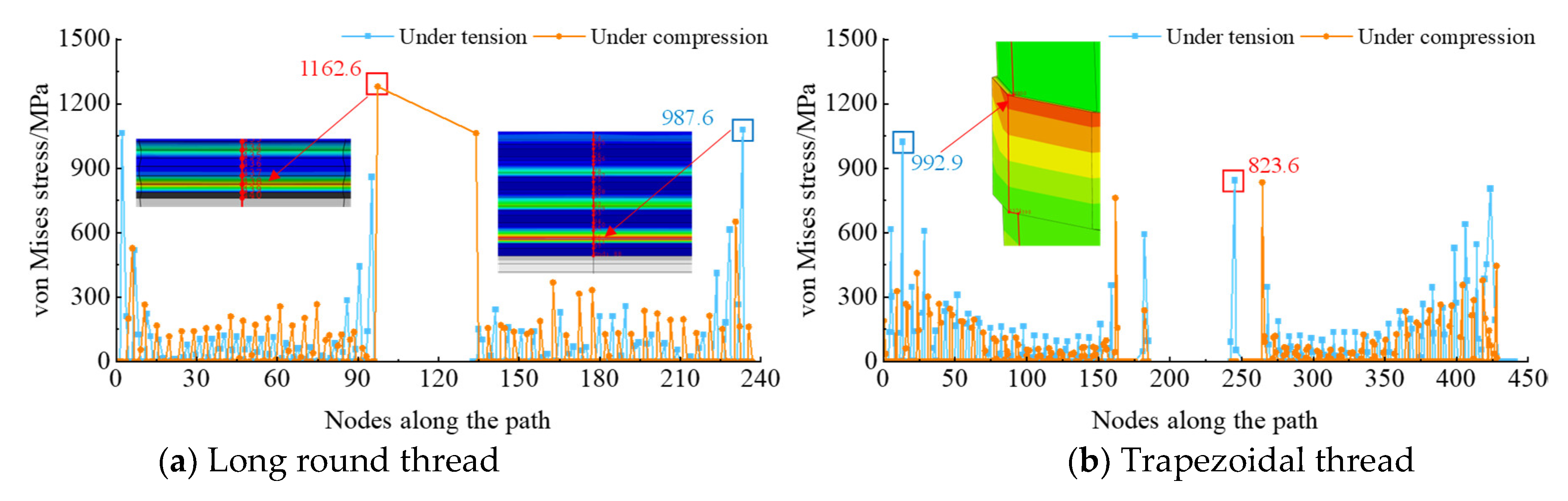
As shown in Figure 32a, the contact pressure value at the contact path on the pin is similar to that of the tooth root at the large end of the upper and lower of the pin on the compressed side of the pin of long round joint, with a maximum contact pressure value of 1077.6 MPa. On the tensile side, a large contact pressure appears at the tooth root of the last upper of the pin, with a maximum contact pressure of 1262.6 MPa. As shown in Figure 32b, the contact pressure distribution of the pin of the trapezoidal joint on the compression and tension sides is similar to that the pin of long round joint. The contact pressure is relatively high at the head and tail teeth to ensure the stability of the thread connection, and the maximum contact pressure value is 1022.9 MPa.
As shown in Figure 33a, the contact pressure distribution of the box on the compression and tension sides is basically the same as that of the pin, with slight differences at the head and tail teeth. The maximum contact pressure occurs at the last tooth where the box of the long round joint meshes with the upper part of the box, with a maximum contact pressure of 1084.7 MPa. As shown in Figure 33b, the contact pressure of the trapezoidal internal thread gradually decreases along the contact path and significantly increases at the shoulder, playing an auxiliary sealing role.
As shown in Table 6, the maximum contact pressure of the box of the long round joint on the tensile side is much smaller than that of the pin. The difference in contact pressure between the pin and box at the same location can lead to poor thread engagement or damage. The maximum contact pressure value and occurrence position of the trapezoidal joint on the compression and tension sides are basically consistent, which can ensure the firmness and durability of the thread connection.
7. Conclusions
- (1)
- The larger the wall thickness, the lower the overall stress and the higher the strength of the thread under the same structure and working conditions. Internal pressure has a significant impact on the stress of the original structural thread, torque has a significant impact on the contact pressure of the two structural threads, and torque and bending moment have a significant impact on the stress of the new structural thread.
- (2)
- Under four different sizes of bending, the stress at the tensile position is smaller, and the stress distribution at the top and bottom of each tooth is more uniform, although all are far below the yield limit.
- (3)
- As the bending stress increases on the tensile side, the contact pressure of the first tooth of the box and the last tooth of the pin of the joint increases with the wall thickness. The high-level contact pressure near the first tooth on the contact path decreases significantly, and the overall contact pressure distribution of the thread teeth becomes more uniform, maintaining the fastening state of the thread joint. At the same time, the contact pressure at the last tooth decreases by more than 300 MPa, and the increase in wall thickness reduces the risk of sticking when the joint is subjected to bending stress.
- (4)
- It shows that the contact pressure of the pin of the original joint with a wall thickness of 9.17 mm is relatively high at the last tooth from the curve of contact pressure. The distribution of contact pressure in the middle section is relatively reasonable.
- (5)
- It shows that the distribution of the contact pressure on the joints with two wall thicknesses is consistent. The contact pressure at the first end of the joint is larger than that in the middle thread section. Compared with the original structure, the contact pressure at the head and tail connections of the new structure is significantly reduced. The improved structure can reduce the risk of sticking when the joint is subjected to internal pressure.
Author Contributions
Conceptualization, C.M. and T.F.; Methodology, Y.D. and Q.M.; Writing—original draft, K.H. and Q.C. All authors have read and agreed to the published version of the manuscript.
Funding
This research received no external funding.
Data Availability Statement
Data are contained within the article.
Conflicts of Interest
Chentao Ma, Kun Huang, Qianwen Mo, Qi Che, and Tiesong Fu are employed by the PetroChina Southwest Oil and Gas Field Company; The remaining author declares that the research was conducted in the absence of any commercial or financial relationships that could be construed as a potential conflict of interest.
References
- Tong, K.; Zhao, J.-L.; Liu, Q.; Zhu, B.; Jin, Q.; Qu, T.-T.; Cong, S. Analysis and investigation of the leakage failure of a casing used in a shale gas well. Eng. Fail. Anal. 2022, 131, 105891. [Google Scholar] [CrossRef]
- Zhang, X.; Li, J.; Zhang, H.; Han, M.; Han, L. Analysis of casing deformation failure mechanism based on fault slip. Eng. Fail. Anal. 2021, 127, 105430. [Google Scholar] [CrossRef]
- Lei, Z. Study on Risk Assessment and Reliability of Casing String under Complex Gas Well; China University of Petroleum (East China): Qindao, China, 2020. [Google Scholar]
- Ke, Y.; Mou, Y. Optimization and application of casing string strength design under high-temperature conditions. China Pet. Mach. 2023, 51, 133–139. [Google Scholar]
- Baojun, L.; Lihua, Q.; Fengping, X. Study on casing strength design method which considers the gas well safety during the whole well life. Drill. Prod. Technol. 2018, 41, 9–12. [Google Scholar]
- Congro, M.; Joakim, H.; Beltrán-Jiménez, K.; Roehl, D. Experimental and numerical study on the pushout shear strength of conventional and expanding cement–casing sections for well integrity. Geoenergy Sci. Eng. 2024, 234, 212638. [Google Scholar] [CrossRef]
- Liu, P.; Li, J.; Yang, H.; Zhang, H.; Lian, W.; Gao, R.; Zhang, X. Study on a new method of controlling casing shear deformation based on hollow glass microspheres cement sheath. Energy Rep. 2022, 8, 5192–5203. [Google Scholar] [CrossRef]
- Jiang, M.; Zhou, F.; Liu, Y.; Ye, G.; Wang, F.; Kang, J. Shear mechanical behavior and stress transfer characteristics of the bilayer casing of gob gas ventholes. Geoenergy Sci. Eng. 2023, 226, 211656. [Google Scholar] [CrossRef]
- Shaygan, K.; Lari, S.H.; Mahani, H. Geomechanical investigation of casing collapse using finite element modeling: The role of cement sheath integrity. Geoenergy Sci. Eng. 2024, 233, 212579. [Google Scholar] [CrossRef]
- Lin, Y.-H.; Zhu, D.-J.; Zeng, D.-Z.; Xian, Q.-B.; He, L.; Sun, Y.-X. Numerical and experimental distribution of stress fields for double shoulder tool joint. Eng. Fail. Anal. 2011, 18, 1584–1594. [Google Scholar] [CrossRef]
- Santus, C.; Bertini, L.; Burchianti, A.; Ioue, T.; Sakurai, N. Fatigue resonant tests on drill collar rotary shouldered connections and critical thread root identification. Eng. Fail. Anal. 2018, 89, 138–149. [Google Scholar] [CrossRef]
- Ferjani, M.; Averbuch, D.; Constantinescu, A. A computational approach for the fatigue design of threaded connections. Int. J. Fatigue 2011, 33, 610–623. [Google Scholar] [CrossRef]
- Yuan, G.J.; Yao, Z.Q.; Han, J.Z. Experimental Research on Stress Field Distribution of Oil Tubing Thread Connection during Make and Break Process. Eng. Fail. Anal. 2004, 11, 537–545. [Google Scholar] [CrossRef]
- Zhuang, Y.; Gao, L.X.; Yuan, P.B. Force analysis and tightening optimization of gas sealing drill, pipe joints. Eng. Fail. Anal. 2015, 58, 173–183. [Google Scholar]
- Chen, F.; Di, Q.; Li, N.; Wang, C.; Wang, W.; Wang, M. Determination of operating load limits for rotary shouldered connections with three-dimensional finite element analysis. J. Pet. Sci. Eng. 2015, 133, 622–632. [Google Scholar] [CrossRef]
- Zhu, X.; Dong, L.; Tong, H. Failure analysis and solution studies on drill pipe thread gluing at the exit side of horizontal directional drilling. Eng. Fail. Anal. 2013, 33, 251–264. [Google Scholar] [CrossRef]
- Shahani, A.R.; Sharifi, S.M.H. Contact stress analysis and calculation of stress concentration factors at the tool joint of a drill pipe. Mater. Des. 2009, 30, 3615–3621. [Google Scholar] [CrossRef]
- Liu, Y.; Lian, Z.; Shi, T.; Sang, P. Fracture failure analysis and research on slip of casing head. Eng. Fail. Anal. 2019, 97, 589–604. [Google Scholar] [CrossRef]
- American Petroleum Institute Standard 6ACRA. Age-hardened Nickel-based Alloys for Oil and Gas Drilling and Production Equipment, 21th, 2015-8. Available online: https://susy.mdpi.com/user/manuscripts/displayFile/355972bb246db9f3eabcf21f0e52aa5a?v=46676612 (accessed on 5 March 2024).
- Oku, Y.; Sugino, M.; Ando, Y.; Makino, T.; Komoda, R.; Takazaki, D.; Kubota, M. Fretting fatigue on thread root of premium threaded connections. Tribol. Int. 2017, 108, 111–120. [Google Scholar] [CrossRef]
- Ryu, Y.; Matzen, V.C. The nonlinear behavior of threaded piping connections: Application using a modified Ramberg-Osgood model. Ocean. Eng. 2016, 127, 1–6. [Google Scholar] [CrossRef]
- Akyildiz, H.K.; Livatyali, H. Effects of machining parameters on fatigue behavior of machined threaded test specimens. Mater. Des. 2010, 31, 1015–1022. [Google Scholar] [CrossRef]
- Liu, J.; Qin, M.; Zhao, Q.; Chen, L.; Liu, P.; Gao, J. Fatigue performances of the cracked aluminum-alloy pipe repaired with a shaped CFRP patch. Thin-Walled Struct. 2017, 111, 155–164. [Google Scholar] [CrossRef]
Figure 1.
Photos of a casing rupture.

Figure 2.
Photos of casing fracture.

Figure 3.
Photos of the samples before and after the tensile test.

Figure 4.
Stress–strain curves of the P110 material.

Figure 5.
Structural and parameters diagram of the long round thread joint.

Figure 6.
Finite element model of the long round thread.

Figure 7.
Stress contour of 9.17 mm wall thickness joint.

Figure 8.
Stress variation curves on two types of wall thickness joint.

Figure 9.
Stress contour of for two different wall thicknesses for a joint.

Figure 10.
Stress curves along paths for two different wall thicknesses for a joint.

Figure 11.
Stress curves along the thread paths for two different wall thicknesses for a joint.

Figure 12.
Stress contour of the 9.17 mm wall thickness joint under bending load.

Figure 13.
Stress curves on two types of wall thickness joint.

Figure 14.
Contact pressure curves on two different wall thicknesses of joints.

Figure 15.
Photos of the 5.5 inch casing thread.

Figure 16.
Photos of sample before and after tensile test.

Figure 17.
Stress–strain curves of the 718 material.

Figure 18.
Schematic diagram of the interference contact between the top and root of special threaded teeth.
Figure 18.
Schematic diagram of the interference contact between the top and root of special threaded teeth.

Figure 19.
Schematic diagram of the cone face sealing structure.

Figure 20.
The parameters of the special thread joint.

Figure 21.
Assembly diagram and mesh model of special threaded joint.

Figure 22.
Stress contour of the different wall thickness joints.

Figure 23.
Stress curves of two different wall thicknesses of a joint under tensile conditions.

Figure 24.
Stress contour of the different wall thickness joints of new structure.

Figure 25.
Stress contour and curves of the 9.17 mm wall thickness joint under internal pressure conditions.
Figure 25.
Stress contour and curves of the 9.17 mm wall thickness joint under internal pressure conditions.

Figure 26.
Stress contour of the new joint of the wall thickness of 9.17 mm under bending load.

Figure 27.
Stress contour of the 10.5 mm wall thickness joint.

Figure 28.
Stress curves of joints under a bending condition of 75 MPa.

Figure 29.
Contact pressure curves of joints under a bending condition of 75 MPa.

Figure 30.
Stress variation curve of external thread.

Figure 31.
Stress variation curve of internal thread.

Figure 32.
Change curve of contact pressure of pin under bending stress.

Figure 33.
Change curve of the contact pressure of the box under bending stress.


Table 1.
Test results of the P110 material.
| Material | Sample | Yield Strength (MPa) | Average (MPa) | Tensile Strength (MPa) | Average (MPa) | Elongation (%) | Average (%) |
|---|---|---|---|---|---|---|---|
| P110 | Number 1 | 681.9 | 676.7 | 790.5 | 770.0 | 19.5 | |
| Number 2 | 675.8 | 773.8 | 19.6 | 19.3 | |||
| Number 3 | 672.4 | 745.6 | 18.8 |
Table 2.
718 Material strength calculation results.
| Outer Diameter/mm | Inner Diameter/mm | Wall Thickness/mm | Steel Grade/ksi | Tensile Strength/MPa | Collapsing Strength/MPa | Internal Pressure Strength/MPa | Collapse Type |
|---|---|---|---|---|---|---|---|
| 139.7 | 121.36 | 9.17 | 140 | 1007.8 | 89.35 | 110.88 | Yield Failure |
| 150 | 1102.5 | 92.91 | 118.8 | ||||
| 118.62 | 10.54 | 140 | 1138.8 | 120.57 | 127.45 | ||
| 150 | 1212.7 | 126.75 | 136.55 |
Table 3.
Maximum stress and contact pressure of 9.17 mm wall thickness joint (MPa).
| Working Condition | Torsion | Tension | Compress | Internal Pressure | Bending | |
|---|---|---|---|---|---|---|
| Stress | Original structure | 963.8 | 881.9 | 999 | 1083.1 | 889.8 |
| New structure | 872 | 699.7 | 866.6 | 863.1 | 1036.6 | |
| Contact pressure | Original structure | 1739.3 | 2008.1 | 1729.8 | 1952.2 | 1279.6 |
| New structure | 933.6 | 988.38 | 959.7 | 975.1 | 1350 | |
Table 4.
Maximum stress and contact pressure of 10.54 mm wall thickness joint (MPa).
| Working Condition | Torsion | Tension | Compress | Internal Pressure | Bending | |
|---|---|---|---|---|---|---|
| Stress | Original structure | 910.9 | 876.9 | 923.6 | 959.5 | 892.5 |
| New structure | 618.5 | 609.2 | 745.3 | 739.1 | 997.9 | |
| Contact pressure | Original structure | 1603.2 | 1669.6 | 1415.9 | 1825.6 | 883.3 |
| New structure | 763.9 | 1352.7 | 1051.9 | 743.4 | 947.3 | |
Table 5.
Contact pressure values of thread joints under different working conditions.
| Working Conditions | Tension/MPa | Compression/MPa | Internal Pressure/MPa | ||
|---|---|---|---|---|---|
| Contact pressure | Pin | Long round | 2008.1 | 1729.9 | 2079.1 |
| Trapezoidal | 2208.8 | 1444.1 | 966.6 | ||
| Box | Long round | 1557.0 | 1675.1 | 1995.7 | |
| Trapezoidal | 855.9 | 1299.2 | 770.4 | ||
Table 6.
Maximum contact pressure under bending conditions.
| Pin | Box | ||||
|---|---|---|---|---|---|
| Long Round | Trapezoidal | Long Round | Trapezoidal | ||
| Contact pressure (MPa) | Compression side | 1162.6 | 992.9 | 1084.7 | 933.6 |
| Tension side | 987.6 | 823.6 | 570.6 | 844.9 | |
Disclaimer/Publisher’s Note: The statements, opinions and data contained in all publications are solely those of the individual author(s) and contributor(s) and not of MDPI and/or the editor(s). MDPI and/or the editor(s) disclaim responsibility for any injury to people or property resulting from any ideas, methods, instructions or products referred to in the content. |
© 2024 by the authors. Licensee MDPI, Basel, Switzerland. This article is an open access article distributed under the terms and conditions of the Creative Commons Attribution (CC BY) license (https://creativecommons.org/licenses/by/4.0/).
Share and Cite
MDPI and ACS Style
Ma, C.; Duan, Y.; Huang, K.; Mo, Q.; Chen, Q.; Fu, T. Research on the Mechanical Properties and Structural Optimization of Pipe String Joint under Deep Well Fracturing Operation. Processes 2024, 12, 835. https://doi.org/10.3390/pr12040835
AMA Style
Ma C, Duan Y, Huang K, Mo Q, Chen Q, Fu T. Research on the Mechanical Properties and Structural Optimization of Pipe String Joint under Deep Well Fracturing Operation. Processes. 2024; 12(4):835. https://doi.org/10.3390/pr12040835
Chicago/Turabian StyleMa, Chentao, Yonggang Duan, Kun Huang, Qianwen Mo, Qi Chen, and Tiesong Fu. 2024. "Research on the Mechanical Properties and Structural Optimization of Pipe String Joint under Deep Well Fracturing Operation" Processes 12, no. 4: 835. https://doi.org/10.3390/pr12040835
Note that from the first issue of 2016, this journal uses article numbers instead of page numbers. See further details here.