Modelling the Nanomechanical Responses of Biofilms Grown on the Indenter Probe


School of Engineering, Newcastle University, Newcastle upon Tyne NE1 7RU, UK
*
Author to whom correspondence should be addressed.
†
These two authors contribute equally to this study, so they are co-first authors.
Processes 2018, 6(7), 84; https://doi.org/10.3390/pr6070084
Submission received: 17 May 2018
/
Revised: 11 June 2018
/
Accepted: 19 June 2018
/
Published: 2 July 2018
(This article belongs to the Section Biological Processes and Systems)
Abstract
:Biofilms have a profound impact on the environment, human health and industrial systems. In order to manage and control them, it is important to measure their mechanical properties intact. Therefore, it has been proposed to grow the biofilms on the atomic force microscope prior to nanoindentation tests with the same probe. However, for nanoindentation of biofilm grown on spherical indenter itself, the existing nanoindentation models become invalid. Therefore, modified models have been proposed to describe the nanoindentation response of biofilm grown on a sphere based on finite element modelling. It was found that the applicability of the models depends on the biofilm thickness and constitutive mechanical models adopted for biofilms. The models developed here would enable more reliable determination of viscoelastic properties of biofilms that grow intact on the indenter itself.
1. Introduction
Biofilms are microorganisms in which cells attach and grow on a surface, and these cells are embedded in an extracellular polymeric matrix [1]. They have a significant impact on human health, industry, and the environment since they are ubiquitous [2]. For instance, biofilm formation on the surface of medical devices, such as heart valves, intravascular catheters, and orthopedic implants, is becoming the major pathogenesis of implant infection [3]. The adhesion and subsequent formation of biofilm will not only increase the risk of infection and morbidity [4], but also cause the corrosion on metal surfaces [5]. Furthermore, as living materials, the attachment and growth of substantial biofilms may affect the microstructure and mechanical properties of the surface [6,7]. Many approaches were adopted to remove the destructive biofilms, such as high-pressure water jet and chemical treatment [8,9]. However, these attempts cannot eliminate the biofilm completely. Further understanding of the mechanical properties of biofilm will be needed to provide better strategies to remove the biofilm.
Nanoindentation, also known as depth-sensing indentation, has been widely used to determine the mechanical properties of synthetic coatings [10] or biological thin films at nanoscale to microscale due to its small probe size [11,12,13,14]. This technique provides the data of indentation load and penetration with ultra-high resolution, from which the mechanical properties can be obtained [15,16,17]. For soft materials, a nanoindentation test with a spherical tip has been widely used to characterize the localized mechanical properties [18,19]. Substantial experimental observations have demonstrated that most biofilms exhibit linear viscoelastic behaviors at small strains [20]. In addition, some biofilms also exhibit nonlinear viscoelastic characteristics at large strains [21]. Understanding such viscoelastic properties of biofilm is important because it actually affects the way to remove the biofilm from the surface efficiently [22]. However, in most studies, the mechanical properties of biofilms were characterized after they were removed from the material surfaces [23]. In such cases, it may affect the integrity of the biofilms prior to mechanical testing.
In order to characterize the nanomechanical properties of intact biofilms, Lau et al. grew biofilms on a spherical indenter, and then this indenter was pressed against with a clean glass surface [2]. In this case, the widely adopted empirical models become invalid, because they were initially proposed for a flat surface and assumed an infinitely small loading period (a step loading). Therefore, in this study, finite element analysis (FEA) was adopted to study the nanomechanical behavior of a biofilm grown on a spherical indenter. Both the linear and nonlinear viscoelastic properties of thin layer biofilms were implemented in the FEA.
2. Materials and Methods
2.1. Finite Element Model (FEM)
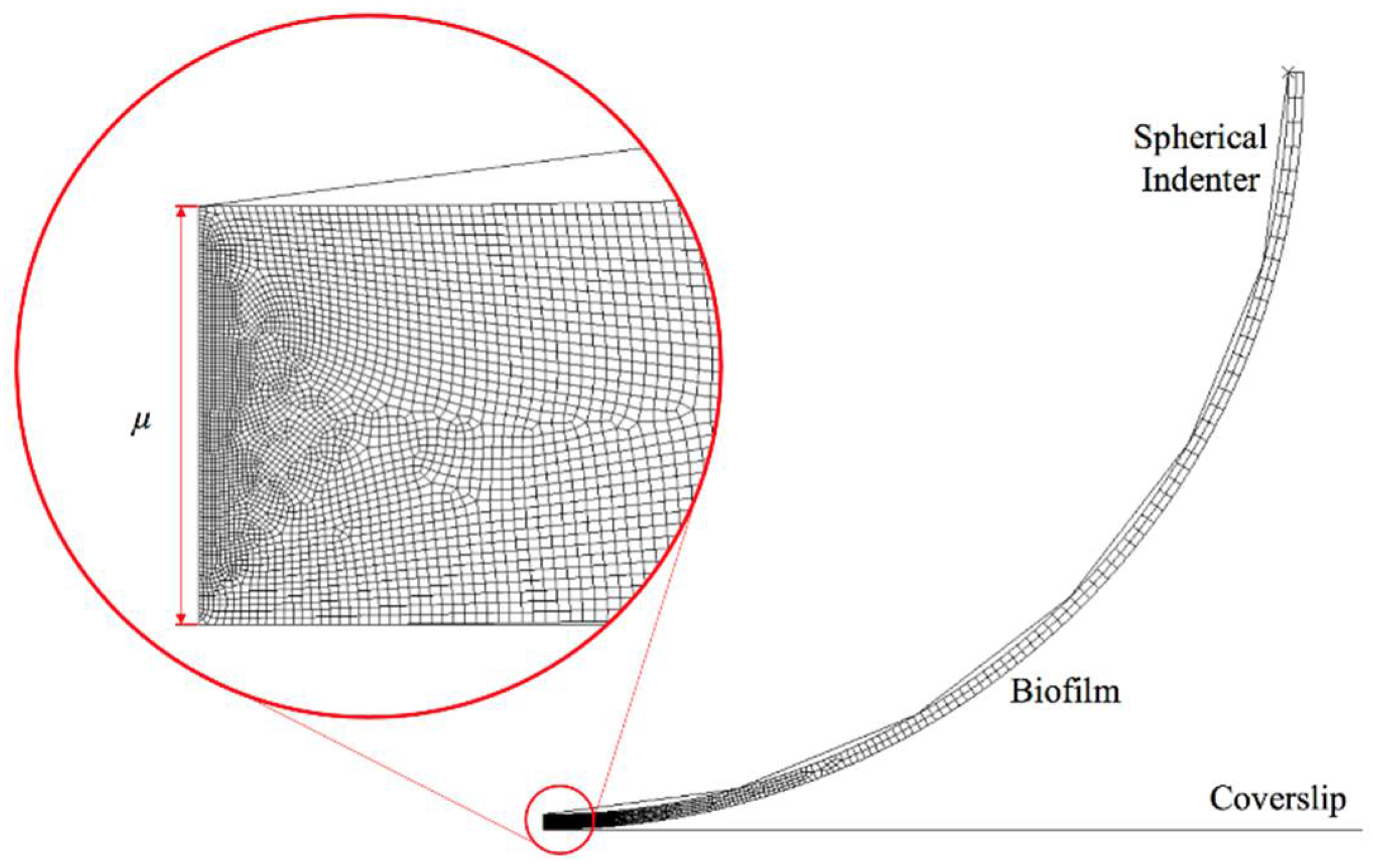
A 2D axisymmetric finite element model was created in ABAQUS 6.10 software. As shown in Figure 1, the biofilms were created as a thin layer attached to a spherical indenter with a tip radius of 25 μm, which represents the experimental setting as described in [2]. In addition, the thickness of biofilms (μ) in this study was assumed to be 0.5 μm and 3 μm, which represent the early stage biofilm (almost monolayer of biofilm) and multilayer biofilm [2]. The interface between the spherical tip and the biofilm was assumed to be perfectly bonded, in such case, there is no separation between the tip and biofilm during and after deformation. The element type is CAX4R (A 4-node bilinear axisymmetric quadrilateral with reduced integration) for the linear viscoelastic material; while CAXA4RH (a 4-node, reduced-integration, hybrid, axisymmetric element with nonlinear asymmetric deformation) was adopted for hyper-viscoelastic material. Both element types are capable for modelling large deformation. In order to capture the deformation of biofilms accurately while enabling computational efficiency, the progressive mesh approach was used, which means that the mesh size becomes smaller as it approaches the indenter. This results in 17,041 and 35,477 elements assigned to 0.5 μm and 3 μm thick biofilms, respectively. The maximum displacement was set as 0.1 μm and 0.6 μm for the thinner and thicker biofilms, in which case the ratio of maximum displacement to thickness was the same. The Young’s modulus of the biofilms was set at 170 kPa [2]. The spherical indenter and the glass coverslip were modelled as a rigid body.
2.2. Linear Viscoelastic Model
The thin biofilm layer was initially modelled as a linear viscoelastic material. Linear viscoelastic material models are composed of simple physical models: springs that are linear components and dashpots that show the viscous behaviors [24]. The Prony series model has been commonly used to express the linear viscoelastic behavior [25,26], in which case, the normalized relaxation modulus could be expressed as:
where is the normalized equilibrium modulus, is a material related constant, and τ is the time constant. Young’s modulus E is defined as,
where is the instantaneous elastic modulus. To simplify the problem, the following parameters were used = 1, = 0.134 and = 0.2 s [27]. In principle, the Poisson’s ratio of the biofilms should be approaching 0.5 because the water content in the biofilm is usually very high. However, depending on the culture conditions, the water concentration for biofilms cultured on an agar plate can be small. In which case the biofilms may have a smaller Poisson’s ratio. Indeed, in other biofilm modelling work, smaller values of the Poisson’s ratios for biofilms have been adopted [28,29]. Therefore, in order to cover the wide range of scenarios, the Poisson’s ratio of biofilm was varied from 0.1 to 0.47 to examine its effects on the nanoindentation response of the biofilm layer.
2.3. Nonlinear Viscoelastic Model
As some biofilms also exhibit nonlinear viscoelastic characteristics at large strains. To account for nonlinear elasticity, hyper-elastic models can be adopted. In this study, Ogden model was used to describe the nonlinear elastic behavior of the thin biofilm layer due to its wide applicability [30]. It correlates the deformation energy (W) to the principal stretch ratio λj (j = 1, 2, 3), shear modulus (μi), and strain stiffening (αi), which is given by,
The same Prony series model as described above was used to describe the viscoelastic component. In this case, the Poisson’s ratio was set as 0.4999, and strain stiffening component was varied from 0.5 to 4 to investigate how this parameter will influence the mechanical response.
2.4. Analytical Viscoelastic Model
Substantial theoretical models have been reported to study the nanomechanical response of biomaterials [31]. Among them, a generalized viscoelastic model for cells was presented by Chen et al. by determining the force-displacement relation [27]. In this model, the Hertz model was optimized by implementing the Prony series model and Boltzmann integrals. During the ramping period, the developed model is given by,
where R is the effective radius, is the Poisson’s ratio. As suggested by Chen et al., for large deformation or indenting an irregular shape, this equation should be further improved by introducing a geometry correction term [27],
where is a dimensionless relative penetration parameter given by h is initially the diameter of the cell, and α = 0.66 + 0.917v − 2.479 for the spherical indenter in contact with spherical cell. In this study, similar models will be adopted, but we introduce the following term to replace the radius of the indenter, which is given by,
where Rtip is the radius of indenter and Rnominal is the nominal effective radius.
3. Results
3.1. New Predictive Model Based on the Analytical Viscoelastic Model
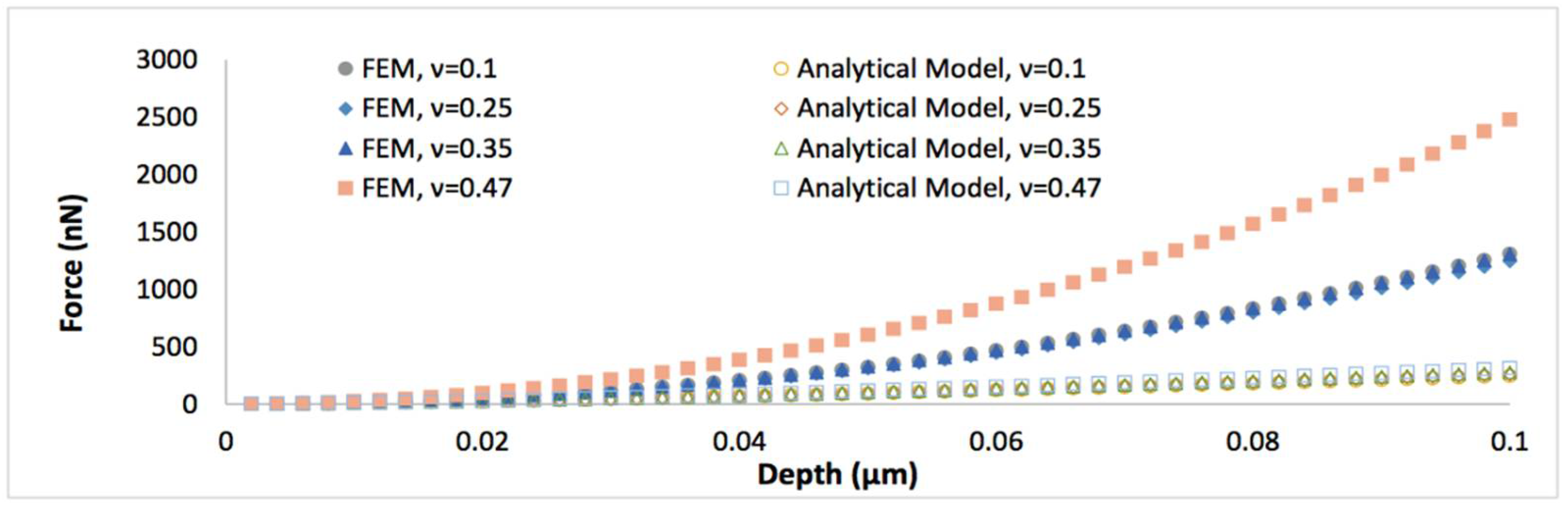
To further understand the nanoindentation responses of biofilms grown on the spherical indenter, the representative von Mises stress contours in thinner biofilm (0.5 µm) with varied Poisson’s ratios are displayed in Figure 2. It can be seen that the maximum von Mises stress decreases with an increase of the Poisson’s ratio. Figure 3 shows the comparison between the simulated force-displacement curves and the analytical model (Equation (4)) for the thinner biofilm with varied Poisson’s ratios. Apparently, Equation (4) underestimates the nanoindentation force at the given penetration. Such a deviation between the FEM and Equation (4) becomes more significant for a larger Poisson’s ratio. Therefore, a geometry term that relates to Poisson’s ratio should be included to improve the accuracy of the analytical viscoelastic model.
It has been found that the effective radius is no longer constant and actually depends on the penetration depth and Poisson’s ratio, which is responsible for the deviation between the FEM and Equation (4). Hence, the existing model needs to be improved by considering the dynamically changing effective R. To start with, a geometry parameter can be introduced to enable the match between the simulated force and the calculated force,
The original geometry term proposed by Chen et al. [27] was initially adopted, however, it underestimated the applied force. Therefore, a refined model with new geometry term is required to quantify the nanomechanical properties of the thin biofilm layer. This new non-dimensional parameter is introduced as,
In which case, Equation (5) can be rewritten as,
A MATLAB code was written to perform the curve fitting and extract the fitting parameter α as a function of Poisson’s ratio. According to the dimensional analysis and the numerical fitting to FEM results, the true effective radius for the linear viscoelastic mode is expressed as,
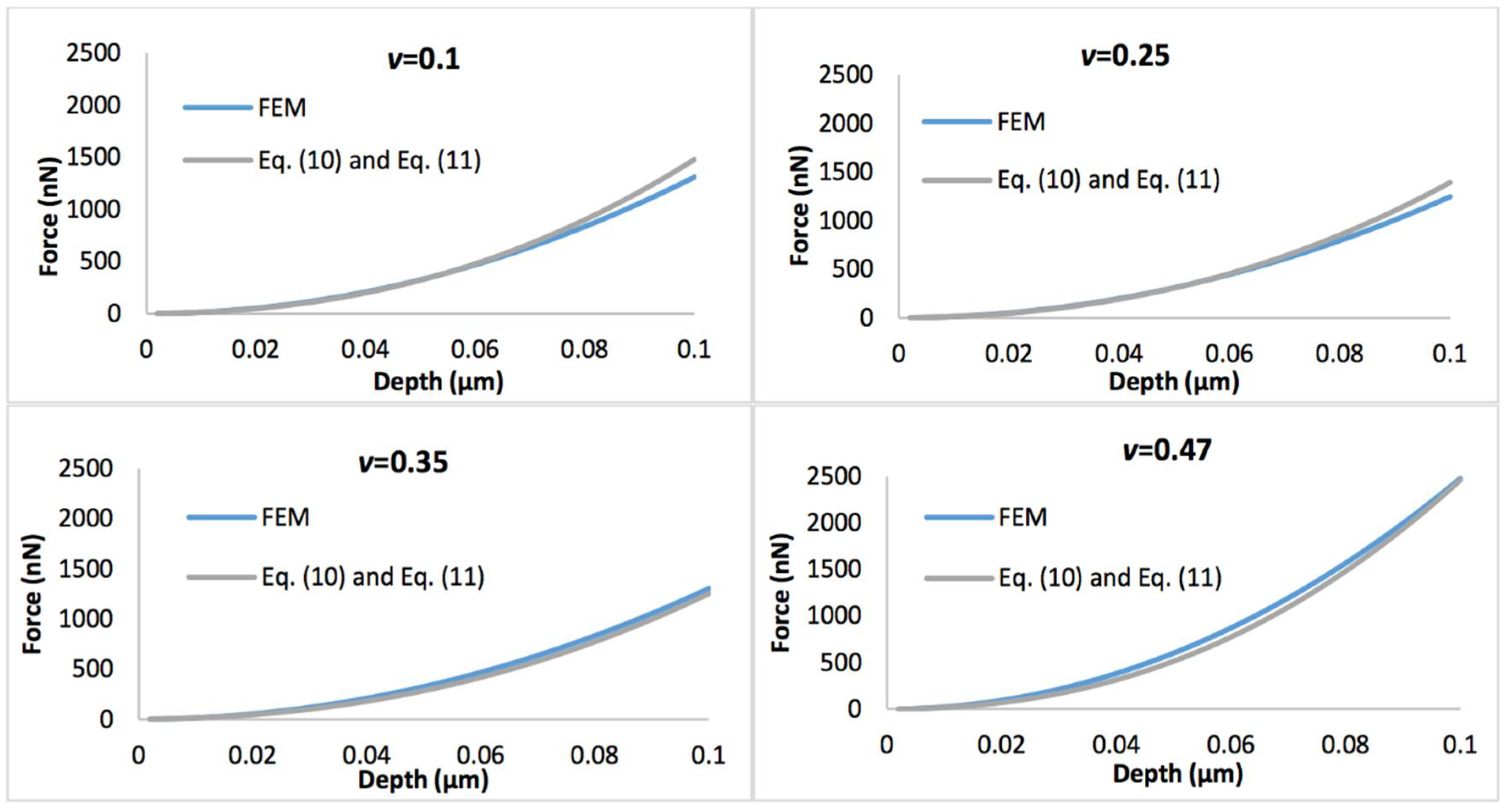
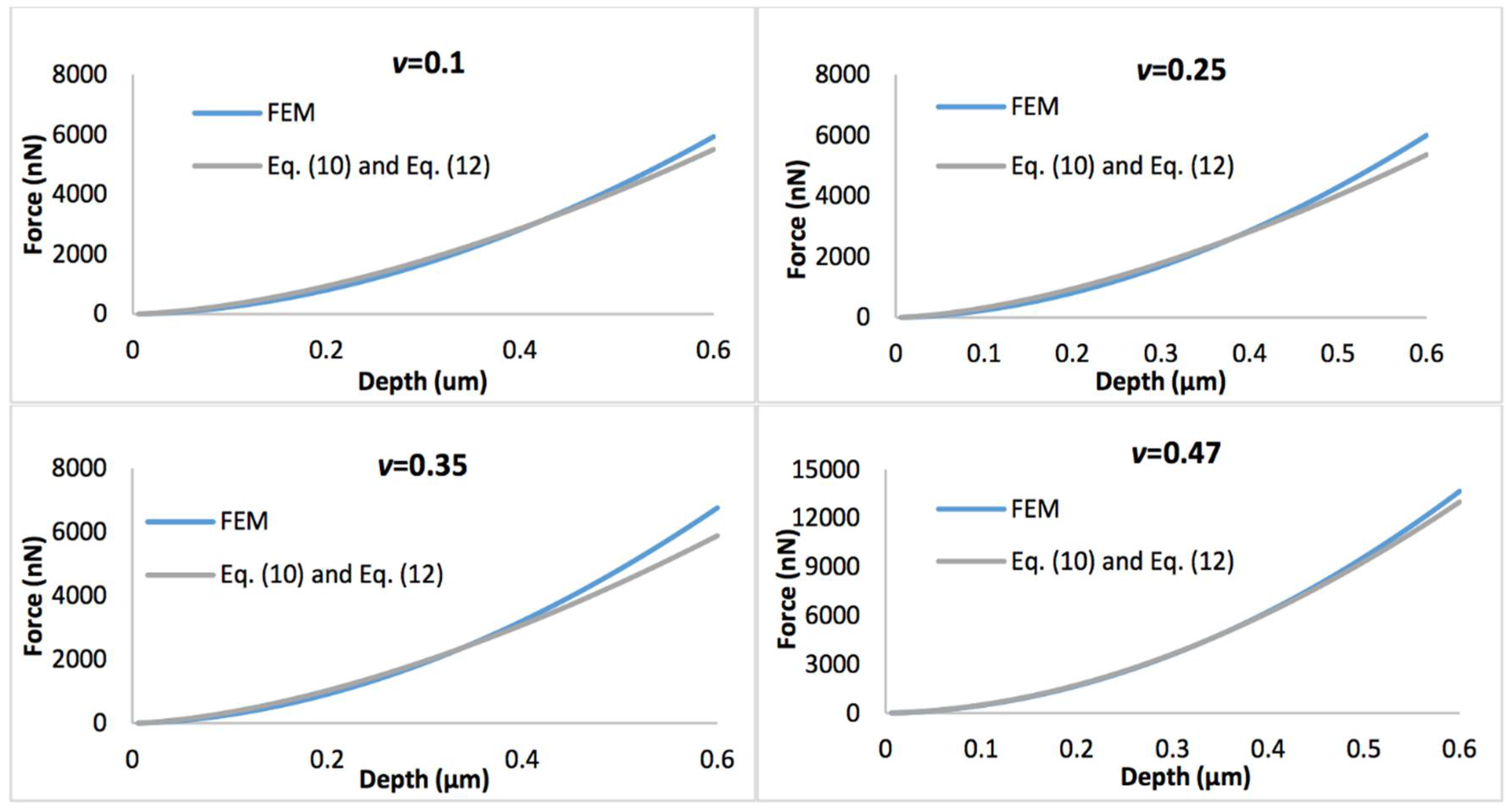
Figure 4 shows the comparison of the simulated force-displacement curves and the refined linear viscoelastic model Equation (10) with geometry term Equation (11), with the biofilm thickness of 0.5 µm. Figure 5 displays the comparison of the simulated force-displacement curves and the refined linear viscoelastic model Equation (10) with geometry term Equation (12), with the biofilm thickness of 3 µm. When Poisson’s ratio is less than 0.35, the deviations between the new predictive model and FEM could be easily observed at a large indentation depth whatever the biofilm thickness. However, this error could be ignored when Poisson’s ratio increases to 0.47.
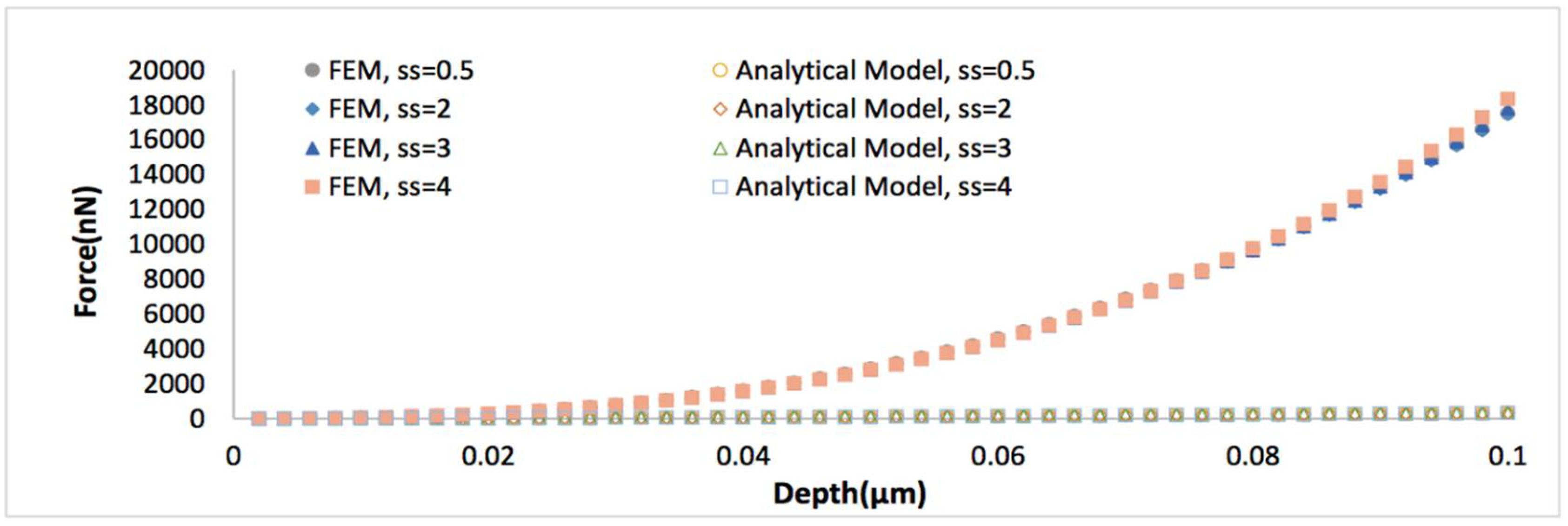
Figure 6 displays the representative von Mises stress contours in thicker biofilm (3 µm) with varied stain stiffening component. It can be seen that the maximum von Mises stress increases with increase of the strain stiffening component. Figure 7 shows the comparison of simulated force-displacement curves and the analytical model Equation (4). It reveals that Equation (4) dramatically underestimates the nanoindentation force at the given penetration depth. Similar to previous work, a predictive model with a modified geometry term (Equation (10)) was adopted to characterize the nonlinear viscoelastic properties of the thin biofilm layer, in this case, the correction parameter α is the function of the strain stiffening component, which is given by,
where is the strain stiffening component.
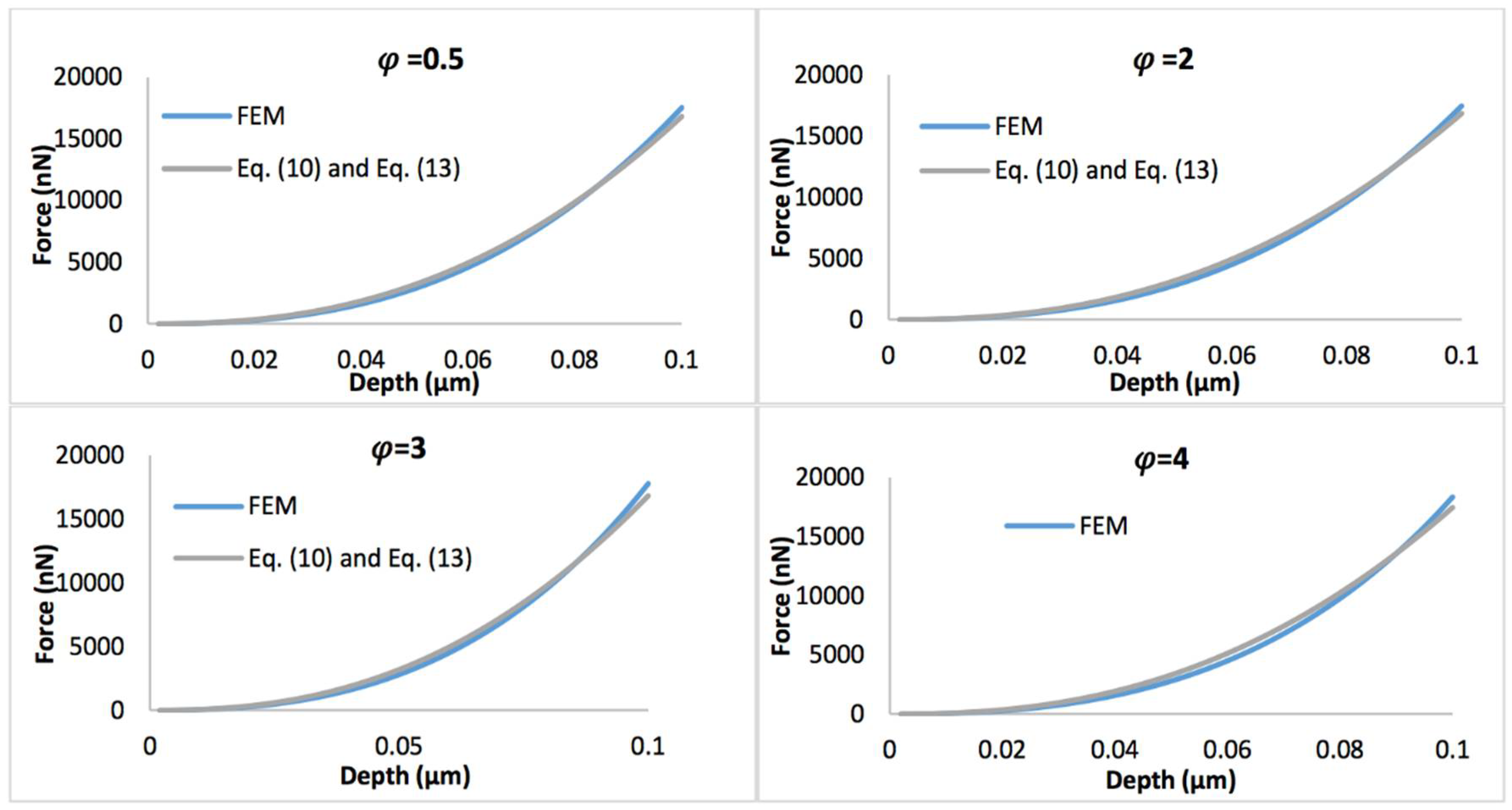
Figure 8 displays the comparison of the simulated force-depth curves and the refined nonlinear viscoelastic model Equation (10) with geometry term Equation (13) when the biofilm thickness equals 0.5 µm. Figure 9 shows the comparison of simulated force-depth curves and refined nonlinear viscoelastic model Equation (10) with geometry term Equation (14) when the biofilm thickness equals 3 µm. It can be seen that the new predictive model is more applicable to describe the nonlinear viscoelastic characteristics of biofilms, particularly for thicker biofilms.
3.2. An Alternative Method
The new model (Equation (10)) works quite well to predict the nanoindentation responses of nonlinear viscoelastic biofilms. For in other cases, there are still visible deviations, particularly for materials with lower Poisson’s ratios. The quadratic polynomial relation is usually used in the curve fitting of the nanomechanical response of coatings [32]. In this study, this relation is also adopted. It is easy to find that the effective R can be expressed as a quadratic polynomial function with respect to depth and Poisson’s ratios. When indenting a thin layer that was adherent to the indenter, is no longer related to the effective indentation strain as demonstrated in Section 3.1. Therefore, for simplification, we correlate the effective radius to dimensionless parameter (indentation penetration relative to biofilm thickness),
where A, B and C are functions of the Poisson’s ratio.
Therefore, Equation (5) is rewritten as,
where is the physical correction parameter. By curve fitting, this parameter is given by,
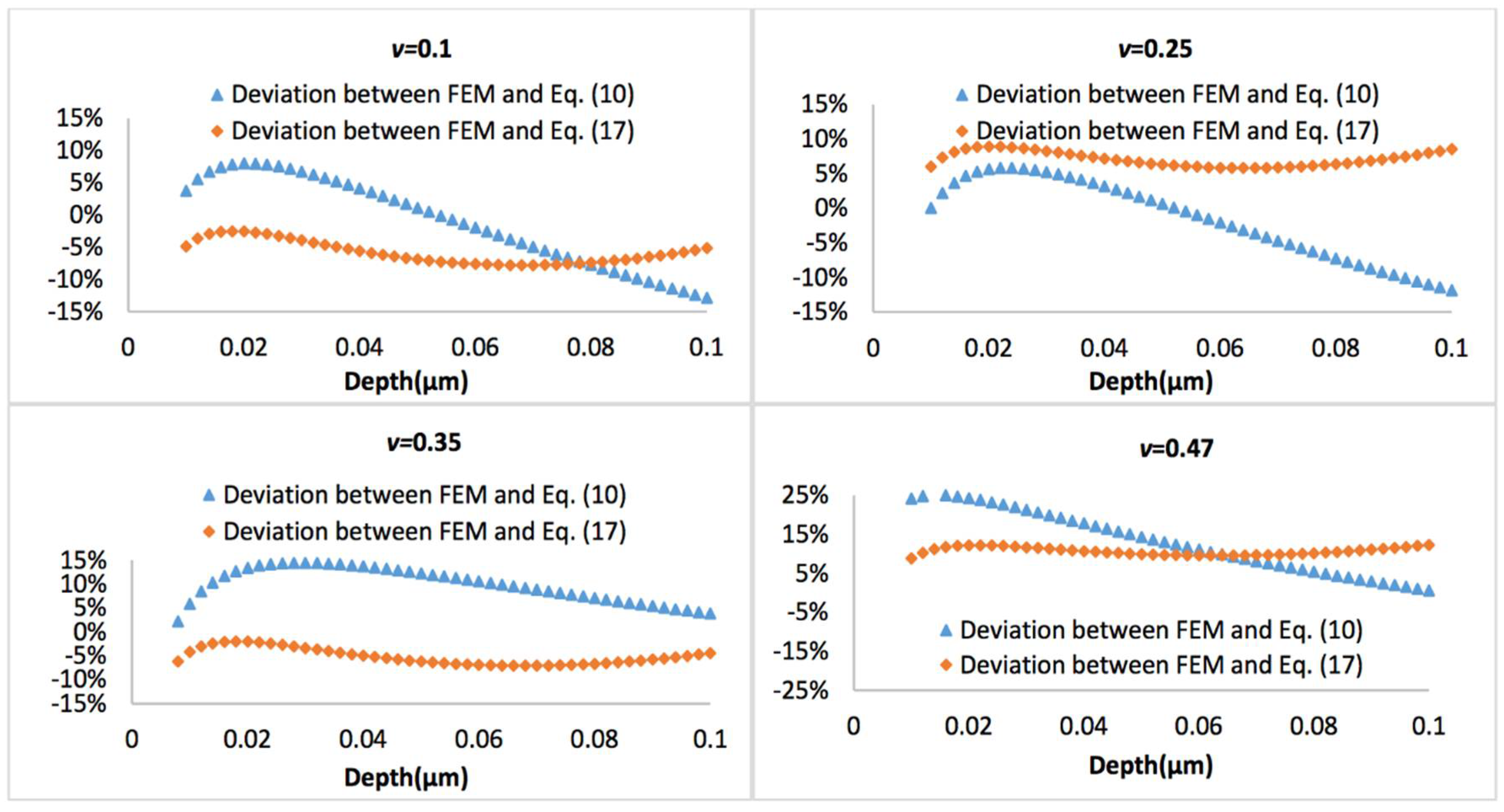
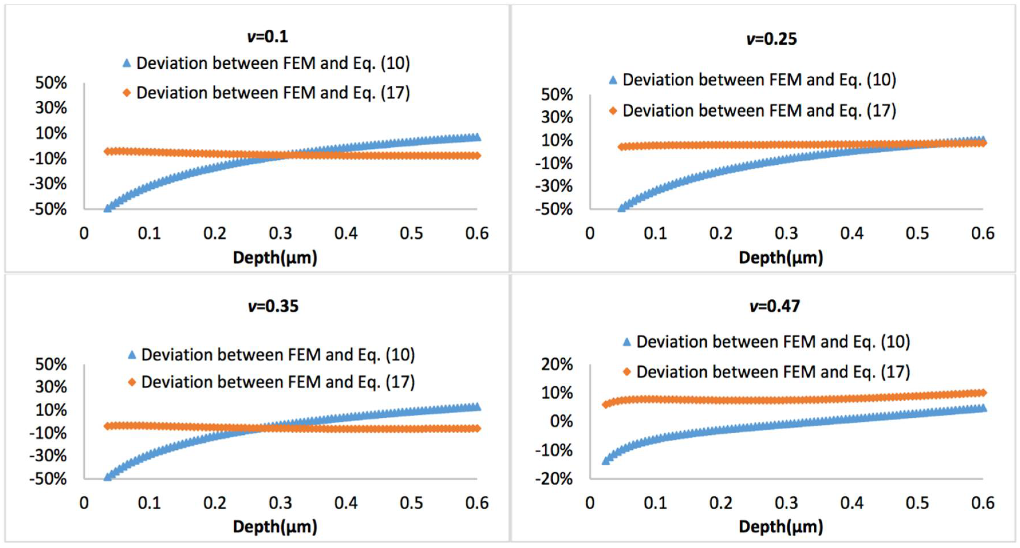
Figure 10 and Figure 11 display the representative deviation between FEM and Equation (10) or Equation (17) at biofilm thickness of 0.5 μm and 3 μm, with the Poisson’s ratio varies between 0.1 and 0.47. It is observed that average errors between Equation (10) and FEM is larger than that between Equation (17) and FEM.
4. Discussion
If the biofilms only exhibit linear viscoelastic characteristics, the new predictive model (Equations (10)–(12)) agrees well with the FEM simulations at a small indentation depth (less than 10% of biofilm thickness), for both thinner and thicker biofilms, regardless of the variation of Poisson’s ratios. At a larger penetration (beyond 10% of biofilm thickness), the deviation between the mathematical model and FEM becomes evident for the Poisson’s ratio below 0.35. Overall, the new linear viscoelastic model is more precise at high Poisson’s ratios (i.e., above 0.35). As shown in Figure 2, with increase of the displacement, the biofilm was gradually squeezed and accumulated into the side. This may change the effective curvature, and explain why the new predictive model underestimated the FEM data for materials with small Poisson’s ratio at large displacement.
When the biofilms have nonlinear viscoelastic behaviors, it can be seen that the new predictive model (Equations (10)–(14)) is in excellent agreement with FEM for both thinner and thicker biofilms, particularly for the latter, regardless of the stiffening components.
If a more complicated relation between the tip radius and the effective tip radius is introduced (see Equation (16)), then the model can also well predict the nanoindentation responses for both thinner and thicker biofilms, which has demonstrated its superior applicability compared to Equation (10). For the thinner biofilm, the deviation between the model (Equation (17)) and FEM is below 10%. Actually, in most cases, such deviation is below 5%, which is a significant improvement compared to Equation (10). For the thicker biofilm, such a deviation is well below 1%. All these have suggested that it is necessary to consider that the geometry correction term is strongly dependent on the relative penetration to biofilm thickness and Poisson’s ratio of biofilm.
5. Conclusions
The commonly used Hertzian contact model is not applicable to determine the mechanical properties for thin films grown on the indenter. This is mainly due to the constant change of the effective curve of the thin film. The empirical model as described in Equation (17) is more reliable to predict the nanoindentation responses of the linear viscoelastic response of biofilm layer regardless of Poisson’s ratio. The refined model with a relatively simple geometry term as seen in Equation (10) is sufficient to describe the nanoindentation responses of the nonlinear viscoelastic behavior of the biofilm layer. Furthermore, it seems that both of these two models are more applicable for thicker biofilms. This suggests that such models are useful to guide the experimental lists to reliably determine the viscoelastic properties of intact multilayer biofilms grown on the indenters. A similar modelling framework can also be extended for mechanical testing of biofilms grown on irregular materials surfaces.
For the present models, the empirical correction parameter α was actually dependent on biofilm thicknesses and other materials parameters (e.g., Poisson’s ratio in linear viscoelastic model and strain stiffening component in nonlinear viscoelastic model). Therefore, a more generalized model should be developed in the future.
Author Contributions
All authors designed and performed research, data acquisition and analysis, and wrote the manuscript. All authors contributed to the final approval of manuscript.
Funding
Engineering and Physical Sciences Research Council (EP/K039083/1).
Conflicts of Interest
The authors declare no conflict of interest.
References
- Walter, M.; Safari, A.; Ivankovic, A.; Casey, E. Detachment characteristics of a mixed culture biofilm using particle size analysis. Chem. Eng. J. 2013, 228, 1140–1147. [Google Scholar] [CrossRef] [Green Version]
- Lau, P.C.Y.; Dutcher, J.R.; Beveridge, T.J.; Lam, J.S. Absolute quantitation of bacterial biofilm adhesion and viscoelasticity by microbead force spectroscopy. Biophys. J. 2009, 96, 2935–2948. [Google Scholar] [CrossRef] [PubMed]
- Sousa, C.; Henriques, M.; Oliveira, R. Mini-review: Antimicrobial central venous catheters-recent advances and strategies. Biofouling 2011, 27, 609–620. [Google Scholar] [CrossRef] [PubMed] [Green Version]
- Kanematsu, H.; Barry, D.M. Biofilm and Materials Science; Springer: Berlin, Germany, 2015. [Google Scholar]
- Beech, I.B.; Sunner, J. Biocorrosion: Towards understanding interactions between biofilms and metals. Curr. Opin. Biotechnol. 2004, 15, 181–186. [Google Scholar] [CrossRef] [PubMed]
- Waters, M.S.; Kundu, S.; Lin, N.J.; Lin-Gibson, S. Microstructure and mechanical properties of in situ Streptococcus mutans biofilms. ACS Appl. Mater. Interfaces 2013, 6, 327–332. [Google Scholar] [CrossRef] [PubMed]
- Cense, A.; Peeters, E.; Gottenbos, B.; Baaijens, F.; Nuijs, A.; Van Dongen, M. Mechanical properties and failure of Streptococcus mutans biofilms, studied using a microindentation device. J. Microbiol. Methods 2006, 67, 463–472. [Google Scholar] [CrossRef] [PubMed]
- Gorur, A.; Lyle, D.M.; Schaudinn, C.; Costerton, J.W. Biofilm removal with a dental water jet. Compend. Contin. Educ. Dent. 2009, 30, 1–6. [Google Scholar] [PubMed]
- Chen, X.; Stewart, P.S. Biofilm removal caused by chemical treatments. Water Res. 2000, 34, 4229–4233. [Google Scholar] [CrossRef]
- Chen, J. On the determination of coating toughness during nanoindentation. Surf. Coat. Technol. 2012, 206, 3064–3068. [Google Scholar] [CrossRef]
- Ebenstein, D.M.; Pruitt, L.A. Nanoindentation of biological materials. Nano Today 2006, 1, 26–33. [Google Scholar] [CrossRef]
- Duan, P.; Chen, J. Nanomechanical and microstructure analysis of extracellular matrix layer of immortalized cell line Y201 from human mesenchymal stem cells. Surf. Coat. Technol. 2015, 284, 417–421. [Google Scholar] [CrossRef]
- Duan, P.; Toumpaniari, R.; Partridge, S.; Birch, M.A.; Genever, P.G.; Bull, S.J.; Dalgarno, K.W.; McCaskie, A.W.; Chen, J. How cell culture conditions affect the microstructure and nanomechanical properties of extracellular matrix formed by immortalized human mesenchymal stem cells: An experimental and modelling study. Mater. Sci. Eng. C 2018, 89, 149–159. [Google Scholar] [CrossRef] [PubMed]
- Chen, J.; Birch, M.A.; Bull, S.J. Nanomechanical characterization of tissue engineered bone grown on titanium alloy in vitro. J. Mater. Sci. Mater. Med. 2010, 21, 277–282. [Google Scholar] [CrossRef] [PubMed]
- Gouldstone, A.; Koh, H.-J.; Zeng, K.-Y.; Giannakopoulos, A.; Suresh, S. Discrete and continuous deformation during nanoindentation of thin films. Acta Mater. 2000, 48, 2277–2295. [Google Scholar] [CrossRef]
- Chen, X.; Vlassak, J.J. Numerical study on the measurement of thin film mechanical properties by means of nanoindentation. J. Mater. Res. 2001, 16, 2974–2982. [Google Scholar] [CrossRef]
- Chen, J.; Bull, S. Multi-cycling nanoindentation study on thin optical coatings on glass. J. Phys. D Appl. Phys. 2008, 41, 074009. [Google Scholar] [CrossRef]
- Chen, J. Nanobiomechanics of living cells: A review. Interface Focus 2014, 4, 20130055. [Google Scholar] [CrossRef] [PubMed]
- Chen, J. Understanding the nanoindentation mechanisms of a microsphere for biomedical applications. J. Phys. D Appl. Phys. 2013, 46, 495303. [Google Scholar] [CrossRef]
- Guélon, T.; Mathias, J.-D.; Stoodley, P. Advances in biofilm mechanics. In Biofilm Highlights; Springer: Berlin, Germany, 2011; pp. 111–139. [Google Scholar]
- Baudez, J.-C.; Gupta, R.K.; Eshtiaghi, N.; Slatter, P. The viscoelastic behaviour of raw and anaerobic digested sludge: Strong similarities with soft-glassy materials. Water Res. 2013, 47, 173–180. [Google Scholar] [CrossRef] [PubMed]
- Peterson, B.W.; He, Y.; Ren, Y.; Zerdoum, A.; Libera, M.R.; Sharma, P.K.; Van Winkelhoff, A.-J.; Neut, D.; Stoodley, P.; Van Der Mei, H.C. Viscoelasticity of biofilms and their recalcitrance to mechanical and chemical challenges. FEMS Microbiol. Rev. 2015, 39, 234–245. [Google Scholar] [CrossRef] [PubMed] [Green Version]
- Böl, M.; Ehret, A.E.; Bolea Albero, A.; Hellriegel, J.; Krull, R. Recent advances in mechanical characterisation of biofilm and their significance for material modelling. Crit. Rev. Biotechnol. 2013, 33, 145–171. [Google Scholar] [CrossRef] [PubMed]
- Tzikang, C. Determining a Prony Series for a Viscoelastic Material from Time Varying Strain Data; Army Research Laboratory: Hampton, VA, USA, 2000. [Google Scholar]
- Park, S.W.; Kim, Y.R. Fitting Prony-series viscoelastic models with power-law presmoothing. J. Mater. Civ. Eng. 2001, 13, 26–32. [Google Scholar] [CrossRef]
- Duan, P.; Bull, S.; Chen, J. Modeling the nanomechanical responses of biopolymer composites during the nanoindentation. Thin Solid Films 2015, 596, 277–281. [Google Scholar] [CrossRef]
- Chen, J.; Lu, G. Finite element modelling of nanoindentation based methods for mechanical properties of cells. J. Biomech. 2012, 45, 2810–2816. [Google Scholar] [CrossRef] [PubMed]
- Ochoa, J.-C.; Coufort, C.; Escudié, R.; Liné, A.; Paul, E. Influence of non-uniform distribution of shear stress on aerobic biofilms. Chem. Eng. Sci. 2007, 62, 3672–3684. [Google Scholar] [CrossRef]
- Picioreanu, C.; Van Loosdrecht, M.C.M.; Heijnen, J.J. Two-dimensional model of biofilm detachment caused by internal stress from liquid flow. Biotechnol. Bioeng. 2001, 72, 205–218. [Google Scholar] [CrossRef]
- Kim, B.; Lee, S.B.; Lee, J.; Cho, S.; Park, H.; Yeom, S.; Park, S.H. A comparison among Neo-Hookean model, Mooney-Rivlin model, and Ogden model for chloroprene rubber. Int. J. Precis. Eng. Manuf. 2012, 13, 759–764. [Google Scholar] [CrossRef]
- Zeng, G.; Vad, B.S.; Dueholm, M.S.; Christiansen, G.; Nilsson, M.; Tolker-Nielsen, T.; Nielsen, P.H.; Meyer, R.L.; Otzen, D.E. Functional bacterial amyloid increases Pseudomonas biofilm hydrophobicity and stiffness. Front. Microbiol. 2015, 6, 1099. [Google Scholar] [CrossRef] [PubMed]
- Cao, G.; Niu, T. Finite element modeling of the indentation behavior of two-dimensional materials. Acta Mech. 2018, 229, 1–10. [Google Scholar] [CrossRef]
Figure 1.
Finite element model for nanoindentation of a thin biofilm layer.

Figure 2.
Von Mises stress contours in thinner biofilm with varied Poisson’s ratio of 0.1 and 0.47 at indentation penetration of 0.1 µm.
Figure 2.
Von Mises stress contours in thinner biofilm with varied Poisson’s ratio of 0.1 and 0.47 at indentation penetration of 0.1 µm.

Figure 3.
The comparison of the simulated force-displacement curves and the analytical model (Equation (4)), when the thickness of biofilm is 0.5 μm and the Poisson’s ratio varies between 0.1 and 0.47.
Figure 3.
The comparison of the simulated force-displacement curves and the analytical model (Equation (4)), when the thickness of biofilm is 0.5 μm and the Poisson’s ratio varies between 0.1 and 0.47.

Figure 4.
Comparison of force-displacement curves determined by the finite element model (FEM) and refined linear viscoelastic model Equation (10) with geometry term Equation (11), with the biofilm thickness of 0.5 µm and the Poisson’s ratio varies between 0.1 and 0.47.
Figure 4.
Comparison of force-displacement curves determined by the finite element model (FEM) and refined linear viscoelastic model Equation (10) with geometry term Equation (11), with the biofilm thickness of 0.5 µm and the Poisson’s ratio varies between 0.1 and 0.47.

Figure 5.
Comparison of force-displacement curves of FEM and refined linear viscoelastic model Equation (10) with geometry term Equation (12), with the biofilm thickness of 3 µm and the Poisson’s ratio varies between 0.1 and 0.47.
Figure 5.
Comparison of force-displacement curves of FEM and refined linear viscoelastic model Equation (10) with geometry term Equation (12), with the biofilm thickness of 3 µm and the Poisson’s ratio varies between 0.1 and 0.47.

Figure 6.
Von Mises stress contours in thicker biofilm with varied strain stiffening component of 0.5 and 4.
Figure 6.
Von Mises stress contours in thicker biofilm with varied strain stiffening component of 0.5 and 4.

Figure 7.
Force versus indentation depth curves comparing the analytical viscoelastic model Equation (4) to the finite element (FE) simulations, when the thickness of biofilm is 0.5 μm, Poisson’s ratio is 0.4999, strain stiffening component ranges from 0.5 to 4.
Figure 7.
Force versus indentation depth curves comparing the analytical viscoelastic model Equation (4) to the finite element (FE) simulations, when the thickness of biofilm is 0.5 μm, Poisson’s ratio is 0.4999, strain stiffening component ranges from 0.5 to 4.

Figure 8.
Comparison of force-displacement curves determined by FEM and refined nonlinear viscoelastic model Equation (10) with geometry term Equation (13), with the biofilm thickness of 0.5 µm and the strain stiffening component varying between 0.5 and 4.
Figure 8.
Comparison of force-displacement curves determined by FEM and refined nonlinear viscoelastic model Equation (10) with geometry term Equation (13), with the biofilm thickness of 0.5 µm and the strain stiffening component varying between 0.5 and 4.

Figure 9.
Comparison of force-displacement curves determined by FEM and refined nonlinear viscoelastic model Equation (10) with geometry term Equation (14), with the biofilm thickness of 3 µm and the strain stiffening component varying between 0.5 and 4.
Figure 9.
Comparison of force-displacement curves determined by FEM and refined nonlinear viscoelastic model Equation (10) with geometry term Equation (14), with the biofilm thickness of 3 µm and the strain stiffening component varying between 0.5 and 4.

Figure 10.
Deviation between the FEM results and Equation (10) or Equation (17), when biofilm thickness is 0.5 µm.
Figure 10.
Deviation between the FEM results and Equation (10) or Equation (17), when biofilm thickness is 0.5 µm.

Figure 11.
Deviation between the FEM results and Equation (10) or Equation (17), when biofilm thickness is 3 µm.
Figure 11.
Deviation between the FEM results and Equation (10) or Equation (17), when biofilm thickness is 3 µm.

© 2018 by the authors. Licensee MDPI, Basel, Switzerland. This article is an open access article distributed under the terms and conditions of the Creative Commons Attribution (CC BY) license (http://creativecommons.org/licenses/by/4.0/).
Share and Cite
MDPI and ACS Style
Xia, Y.; Duan, P.; Chen, J. Modelling the Nanomechanical Responses of Biofilms Grown on the Indenter Probe. Processes 2018, 6, 84. https://doi.org/10.3390/pr6070084
AMA Style
Xia Y, Duan P, Chen J. Modelling the Nanomechanical Responses of Biofilms Grown on the Indenter Probe. Processes. 2018; 6(7):84. https://doi.org/10.3390/pr6070084
Chicago/Turabian StyleXia, Yuqing, Pengfei Duan, and Jinju Chen. 2018. "Modelling the Nanomechanical Responses of Biofilms Grown on the Indenter Probe" Processes 6, no. 7: 84. https://doi.org/10.3390/pr6070084
Note that from the first issue of 2016, this journal uses article numbers instead of page numbers. See further details here.