Ambient Pressure-Dried Graphene–Composite Carbon Aerogel for Capacitive Deionization


Shanghai Key Laboratory of Special Artificial Microstructure Materials and Technology, School of Physics Science and Engineering, Tongji University, Shanghai 200092, China
*
Authors to whom correspondence should be addressed.
Processes 2019, 7(1), 29; https://doi.org/10.3390/pr7010029
Submission received: 27 November 2018
/
Revised: 20 December 2018
/
Accepted: 3 January 2019
/
Published: 8 January 2019
(This article belongs to the Special Issue Renewable Energy in Water Desalination: Model Based Approach)
Abstract
:Capacitive deionization (CDI) technology possessing excellent desalination performance and energy efficiency is currently being widely studied in seawater desalination. In this work, the graphene–composite carbon aerogels (GCCAs) easily prepared by an ambient pressure drying method served as electrodes to remove salt ions in aqueous solution by CDI. The microstructure of the obtained GCCAs was found to depend on the component content in the precursor solution, and could be controlled through varying the mass ratio of resorcinol and formaldehyde to graphene oxide (RF/GO). The surface characteristics and microstructure of GCCAs were characterized by Raman spectroscopy, X-ray photoelectron spectroscopy (XPS) and scanning electron microscopy (SEM). In addition, the electrochemical tests and CDI experiments of GCCA electrodes were conducted in NaCl solution. Thanks to the reasonable pore structure and highly conductive network, GCCA-150 achieved the best salt adsorption capacity of 26.9 mg/g and 18.9 mg/g in NaCl solutions with concentrations of 500 mg/L and 250 mg/L, respectively.
1. Introduction
Capacitive deionization (CDI) is an emerging technology used to remove charged ions from salt solution. Theoretically, CDI is an electrochemical method that forms electric double layers (EDLs) on the surface of pores inside the electrode to promote the ions’ adsorption under the electrostatic field, thus generating a decrease in the concentration of the solution and producing deionized water [1,2]. Due to its unique superiorities involving high coulombic efficiency, low energy consumption and no secondary pollution, CDI is currently being widely studied in the field of seawater desalination [3,4,5,6].
Reasonable design of the structure of the CDI unit can further enhance the desalination capacity [7,8,9]. S. Porada [10] and K. Dermentzis [11] et al. presented novel continuous capacitive deionization systems, where the adsorption and desorption cycles were repeated infinitely, and the deionization process was continuously performed. On the other hand, improvements in CDI performance can also be achieved by developing suitable electrode materials, whose properties can greatly affect the CDI performance. Various carbon-based materials involving activated carbon [12], carbon nanotubes [13], mesopores carbon [14], carbon aerogels (CAs) [15,16] and composites thereof [17,18] have been used as CDI electrodes, whose properties greatly affect the CDI performance. Among these porous carbon materials, CAs are the most prospective material for CDI [19,20,21], as their high specific surface area (SSA), decent electronic conductivity and excellent electrochemical stability [22,23,24] allow them to play crucial roles as electrodes for adsorbing ions from the salt solution. Currently, new strategies towards optimal morphologies and suitable electrochemical behavior of CAs are urgently necessary for the improvement of adsorption performance [25,26].
Owing to the unique honeycomb-like single-layer structure and superior electrical conductivity (~7200 S/m), graphene has become the material of choice for modification of the carbon aerogels [27,28,29]. However, the combination of graphene with other materials was generally realized with graphene oxide (GO) as an intermediary. GO possesses rich oxygen-containing functional groups that can help GO and the polymer to form strong interactions, which is beneficial for the structural stability [30]. X. Wang et al. [31] developed a novel flexible GO–metal composite carbon aerogel using metal ions as catalyst and linker. This aerogel was used to adsorb dye pollutants, and exhibited good removal efficiency and cycle stability due to its excellent compressibility. X. Xia et al. [32] prepared graphene-doped carbon cryogels by freeze drying, which displayed high specific capacitance and superior rate capability. However, there are few studies focusing on the composition of carbon aerogels and graphene by the ambient drying method, let alone their application in the field of CDI. In this work, graphene–composite carbon aerogels (GCCAs) were synthesized by an ambient pressure drying method followed by carbonization, and were assembled for desalination experiments. The microstructure of GCCAs was controlled through adjusting the mass ratio of resorcinol and formaldehyde to GO (RF/GO) in precursor solution. The surface morphology, microstructure, electrochemical behaviors and electrosorption performance were tested and analyzed.
2. Materials and Methods
2.1. Synthesis of GCCAs
The GO dispersion liquid used in this work was purchased from Nanjing MKNANO Tech. Co., Ltd., Nanjing, China (www.mukenano.com), and its concentration was 4 mg/mL. GCCAs were synthesized via the blending of precursors and sol–gel polycondensation. Resorcinol (R) (Sinopharm Chemical Reagent Co., Ltd., Shanghai, China), formaldehyde (37 wt % in H2O, F) (Sinopharm Chemical Reagent Co., Ltd., Shanghai, China), sodium carbonate solution (0.05 M, C) (Sinopharm Chemical Reagent Co., Ltd., Shanghai, China), GO dispersion and deionized water were mixed and stirred for 1 h. The molar ratios of R/F, R/C and the mass concentration of R and F were 0.5, 800 and 20 wt %, respectively. The mass ratios of R and F to GO (RF/GO) were varied from 300 to 50. Then, the mixture was transferred to sealed bottles and cured at 90 °C for 72 h. Then, these wet gels were immersed in alcohol (Sinopharm Chemical Reagent Co., Ltd., Shanghai, China) for solvent exchange, followed by the subsequent drying under ambient pressure to get aerogels. GCCAs were then obtained via the carbonization of the dried aerogels in a tubular furnace at a temperature of 1000 °C under pure nitrogen flow of 300 mL/min for 3 h. The samples were named as GCCA-x, where x represents the value of RF/GO in the precursor solution. As a comparison, pure carbon aerogel derived from the polycondensation of resorcinol and formaldehyde (CRF) was fabricated in the same condition without GO.
2.2. Material Characterizations
The Raman spectra were collected using a micro Raman apparatus (Jobin-Yvon HR800, HORIBA Scientific, Lille, France) from 800 to 2000 cm−1 with an argon ion laser emitting at 514 nm. The elemental analysis was detected using X-ray photoelectron spectroscopy (XPS, ESCALAB 250 Xi, ThermoFisher Scientific, Waltham, MA, USA). The scanning electron microscope (SEM, Philips XL30 FEG, Royal Dutch Philips Electronics Ltd., Amsterdam, Netherlands) was used to characterize the surface morphology of the samples. A N2 adsorption analyzer (TriStar 3000, Micromeritics Instruments Corporation, Norcross, GA, USA) was used for the N2 adsorption/desorption isotherm at 77 K. The specific surface area (SSA) was then obtained using Brunauer–Emmett–Teller (BET) calculation from the adsorption branch. The pore size distributions of micropores and mesopores were deduced using Horvath–Kawazoe (HK) and Barrett–Joyner–Halenda (BJH) methods, respectively.
2.3. Electrochemical Tests and CDI Experiments
The resultant GCCA powders, polyvinylidene fluoride (PVDF, as a binder, Sinopharm Chemical Reagent Co., Ltd., Shanghai, China), and acetylene black (as a conductive agent, Sinopharm Chemical Reagent Co., Ltd., Shanghai, China) with a mass ratio of 8:1:1 were mixed in N-methyl pyrrolidone (NMP, Sinopharm Chemical Reagent Co., Ltd., Shanghai, China) and stirred for 24 h to ensure homogeneity. Afterwards, the slurry mixture was coated onto the dry nickel foams with an area of 1 cm2 for electrochemical measurements and onto the graphite papers (10 × 10 cm2) with the area of 6 × 6 cm2 for CDI experiments. The coated nickel foams and graphite papers were finally dried in a vacuum oven at 100 °C for 10 h to obtain the GCCA electrodes.
The electrochemical characterization containing cyclic voltammetry (CV) and electrochemical impedance spectroscopy (EIS) was tested at a three-electrode electrochemical workstation (CHI 660C, CH Instruments, Inc., Austin, TX, USA) with NaCl (Sinopharm Chemical Reagent Co., Ltd., Shanghai, China) aqueous solution (500 mg/L) as electrolyte. Here, GCCA electrode, platinum sheet and saturated calomel electrode were used as the working electrode, counter electrode and reference electrode, respectively. The voltage range of the CV test was from −0.5 to 0.5 V, while the frequency range of EIS spectra was from 0.01 to 105 Hz.
For the CDI experiments, two GCCA electrodes were placed face to face, divided by non-woven fabrics to prevent short circuit, and assembled into a home-made CDI cell. The cell was involved in a batch-mode system where the recycled solution was pumped to the feed tank by a peristaltic pump (Shanghai HUXI Instrument Co., Ltd., Shanghai, China), with a constant flow rate of 25 mL/min. The deionization was performed under a direct voltage of 1.5 V. Continuous magnetic stirring was used to avoid the concentration gradient of the NaCl solution during the experiment. The variation in the ionic concentration was real-time monitored using an ionic conductivity meter (DDSJ-308A, INESA Scientific Instrument Co., Ltd., Shanghai, China ) to detect its conductivity. After the experiment, the salt adsorption capacity (SAC) was calculated as follows:
where C0 and C (mg/L) represent the initial and final concentration of NaCl solution, respectively, V (L) is the volume of NaCl solution, and m (g) is the mass of GCCA in the electrode.
3. Results and Discussion
3.1. Physicochemical Characterization of GCCAs
Raman spectroscopy is an effective method to study the molecular structure of carbon-based materials. Figure 1 displays the Raman spectra of GO, GCCA-150 and CRF. The peaks located at around 1342 and 1598 cm−1 are ascribed to the D- and G-bands, respectively. The D-band reflects the disorder and defects during the preparation process, while the G-band is ascribed to the stretching motion of carbon atoms in the benzene ring, and reflects the symmetry and degree of graphitization [33]. The ratios of ID/IG for different samples are marked in Figure 1. The ID/IG of CRF (1.04) is larger than that of GO (0.94), indicating that GO has a higher degree of graphitization. GCCA-150 presents an ID/IG of 1.08, which is higher than those of GO and CRF. This is due to the introduction of carbon nanoparticles on graphene sheets, which increases the disorder of graphene, and implies the interaction between the surface of graphene sheets and carbon particles.
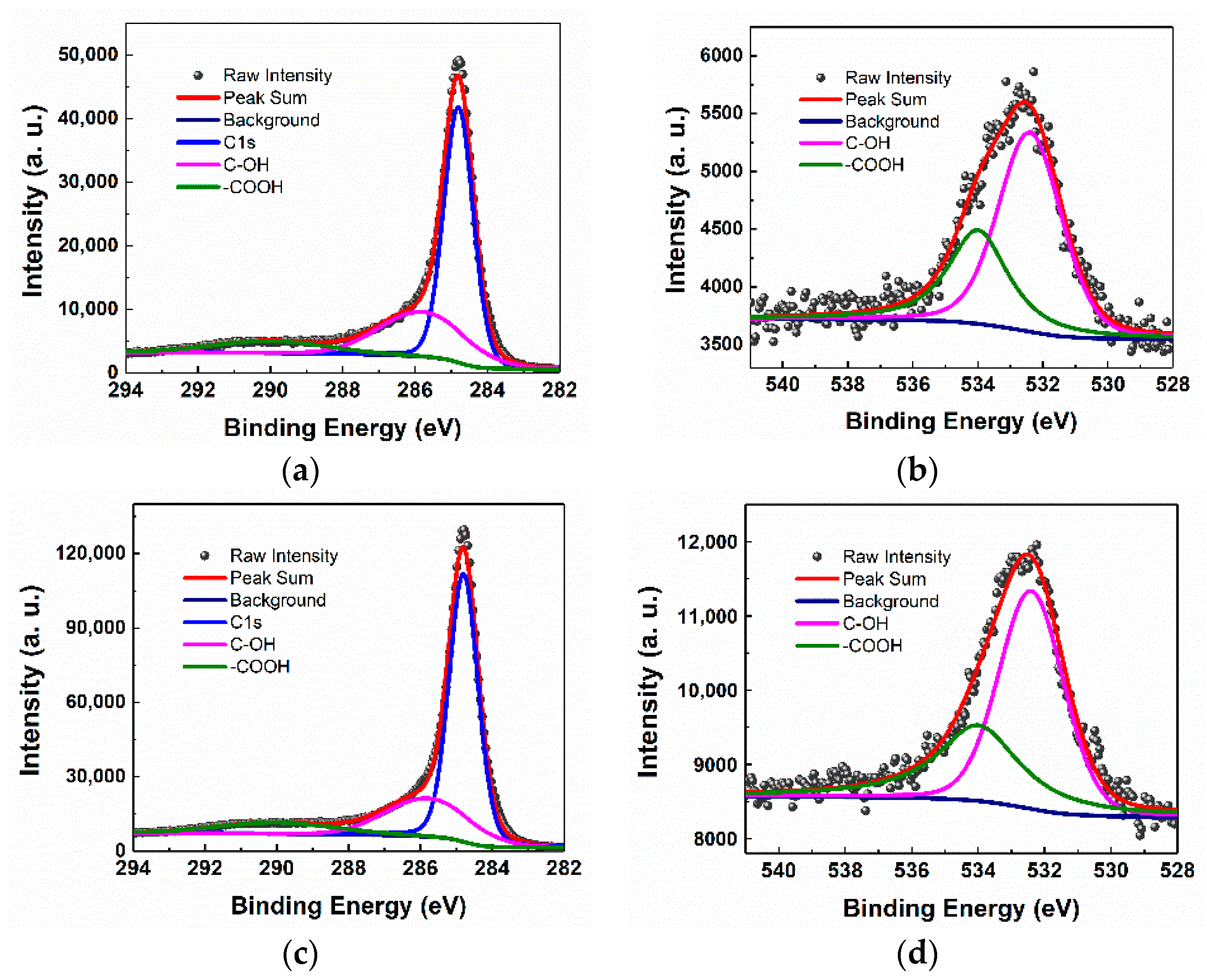
XPS spectra of the C 1s and O 1s for CRF and GCCA-150 (Figure 2) were performed to compare the change of elemental content before and after composition. As shown in Figure 2a,c, the overall profile of C 1s can be deconvoluted into three Gaussian components. The largest peak appearing at 284.8 eV is attributed to graphitic carbon (sp2 configuration) [34]. Satellite peaks at 285.8 eV and 290.0 eV are assigned to hydroxy and carboxyl groups, respectively [35]. For O 1s XPS spectra, two components are deconvoluted, which are ascribed to hydroxy (532.4 eV) and C=O (534.0 eV) in carboxyl [36]. After the introduction of GO, the intensity of the hydroxyl content in GCCA-150 drops while the carboxyl content increases. The detected oxygen atomic percentage of CRF is 3.90% and that of GCCA-150 is 2.55%, indicating that the ratio of O/C decreases by only 1.44%. These results demonstrate that only a small quantity of oxygen-containing functional groups are removed after GO is incorporated. The introduction of GO almost did not change the functional groups on the surface of the carbon aerogel.
3.2. Surface Morphology and Pore Structure of GCCAs
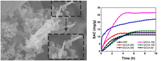
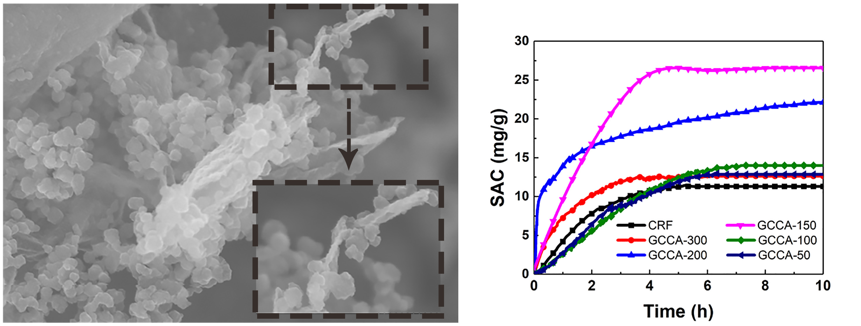
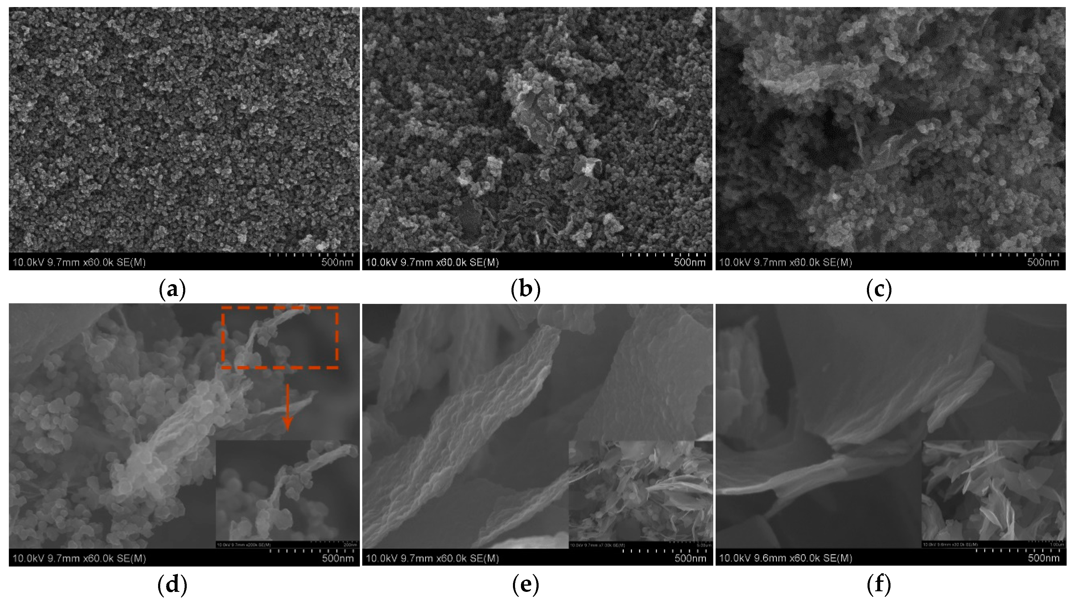
The microstructure of different composite aerogels was characterized by SEM and N2 adsorption/desorption measurements. As can be seen in Figure 3a, CRF shows a three-dimensional interconnected network that consists of aggregated nanoparticles. During the sol–gel process, R and F have addition reactions under basic catalyst producing methylol derivatives (RF primary particles or RF molecules). These primary particles further crosslink by polycondensation with methylene bonds or ether linkages to form RF secondary particles (RF nanoparticles), eventually forming the three-dimensional particle-packed skeleton structure. In addition, there are many oxygen functional groups on GO sheets involving hydroxyl, carboxyl and epoxy groups. After GO sheets are incorporated, RF primary particles preferentially adhere to GO sheets because of the interfacial bonding among oxygen-containing groups provided by the two components [29]. The RF molecules on the GO sheets poly-condense with each other and further crosslink to form RF nanoparticles. With the process of the reaction, RF nanoparticles continuously grow and accumulate due to the limited sites of GO sheets. As shown in Figure 3b,c, graphene sheets disperse uniformly in CA matrix and interconnect with each other. When RF/GO is 150 (Figure 3d), distinct graphene sheets can be observed. Carbon nanoparticles crosslink with each other and also with graphene sheets, shown in the inset of Figure 3d. Thus, it shows a hybrid network structure consisting of carbon nanoparticle-decorated graphene. As RF/GO decreases, sheets with wrinkled texture appear. From the inset of Figure 3e, we can also see several isolated carbon spheres dispersed around the graphene sheets. This is due to the self-crosslinking between the rest of the free RF primary particles. For GCCA-50, it is mainly composed of thickened sheets with no obvious nanoparticles. Meanwhile, from the different surface flatness of the sheets in Figure 3e,f, there are many bulges on the rugged surface of GCCA-100, while the surface of GCCA-50 is relatively neat, which indicates the almost entire polymerization of R and F on the GO sheets. These results show that RF nanoparticles crosslink and grow with GO sheets, which prevents the aggregation of GO sheets and makes them uniformly distribute in the composite aerogels. Thereby, GCCAs have the three-dimensional network structure made up of randomly oriented graphene sheets with carbon nanoparticles. The homogeneous dispersion and cross-connection between RF nanoparticles and GO sheets form an effective pore structure which may enhance the ion transport capability.
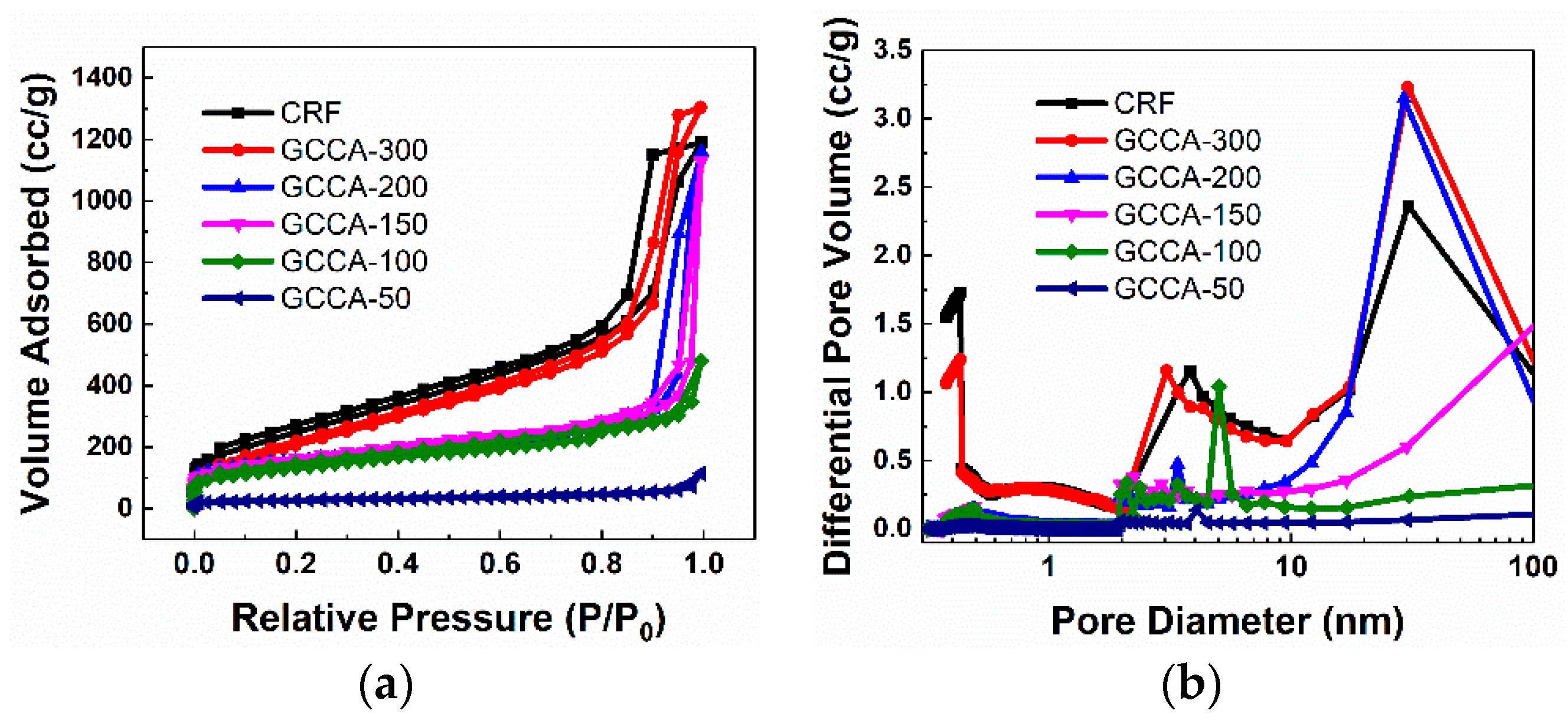
The pore structures of different GCCAs characterized using N2 adsorption/desorption measurements are displayed in Figure 4. CRF and GCCA-300 show the typical type IV curve with type H2 hysteresis loop, which suggests that they contain mainly mesopores with a small proportion of micropores. With the increase of GO, the isotherms of GCCAs turn into type II combined with type H3 hysteresis, indicating the structure with mesopores of plate-piled pores and macropores. Additionally, the hysteresis loops diminish with the decrease of RF/GO, indicating the reducing amount of mesopores. GCCA-50 shows very low nitrogen adsorption, implying that there are few pores in this composite aerogel due to the aggregation of GO. The corresponding pore size distributions calculated using HK and BJH methods are given in Figure 4b. Obviously, both CRF and GCCA-300 exhibit a large amount of micropores and mesopores, and their N2 adsorption capacity corresponding to the pore volume is much more than that of other GCCAs. As shown in the N2 adsorption/desorption isotherm, GCCA-200 and GCCA-150 mainly consist of mesopores and macropores whose size is mainly above 20 nm. As the mass ratio of GO in the precursor increases, the pore size and distribution become small and narrow, and GCCA-50 shows very few pores. Table 1 lists the detailed pore structure parameters of CRF and GCCAs prepared with different RF/GO. The SSA and micropore SSA decline with the increase of GO content. Similarly, the volume of total pores and micropores also gets less and less with the increase of GO. However, GCCA-150 shows a minimal ratio of micropores to total pores. Combining with the SEM results, GCCA-150 possesses a loose texture with a well-developed porous structure.
3.3. Electrochemical Characterization and Electrosorption Measurements
The CV and EIS tests were carried out to investigate the electrochemical responses and dynamic characteristics of ion transfer on the solid/liquid interface of GCCA electrodes. The CV curves were measured at a scanning rate of 10 mV/s with a potential window of −0.5 to 0.5 V in 500 mg/L NaCl aqueous solution, and are shown in Figure 5a. Apparently, all the curves show symmetric shapes, indicating the reversibility of the electrosorption process. The specific capacitance of samples can be calculated by the integrated area of the charging and discharging curves. The CRF electrode presents the minimum area corresponding to the lowest capacitance, although it has the largest SSA. It can be discerned that all graphene–composited carbon aerogel electrodes exhibit larger specific capacitance than that of the CRF electrode, although their SSA is lower. Thus, we can infer that the specific capacitance of a carbon aerogel does not only depend on its SSA. The GCCA-150 electrode shows the largest specific capacitance, and the enhanced electrochemical performance should be attributed to its reasonable pore structure and good conductive network. In Figure 5b, we show the EIS results of the CRF, GCCA-150 and GCCA-50 electrodes performed in a NaCl solution of 500 mg/L. The Nyquist plots of all the samples exhibit a semicircle in the intermediate-frequency region and a sharp increase in the low-frequency range. The semicircles here represent the charge-transfer resistance [37]. The smaller the size of the semicircle, the lower the charge-transfer resistance, and also the faster the transfer of ions and electrons. Compared with the CRF, the diameter of the semicircle for GCCA-150 is smaller, indicating that GCCA-150 has a much lower resistance than that of CRF. Additionally, the tilted lines at low frequency are related to the Warburg impedance which is produced by the diffusion of the electrolyte ions inside electrodes [38]. GCCA-150 shows a line with a higher slope at low frequency than that of CRF, suggesting the good diffusion of salt ions in the pores of the GCCA-150 electrode, which may benefit from the combination of graphene with good conductivity and the well-connected pore network of GCCA-150 [38]. When RF/GO declines to 50, the size of the semicircle gets larger and the slope angle at low frequency becomes smaller, which correspond to a degradation of electrical conductivity performance. This result may be due to the fact that the agglomeration of the excess GO hinders the interconnection among graphene nanosheets and results in the declined electrical properties [32].
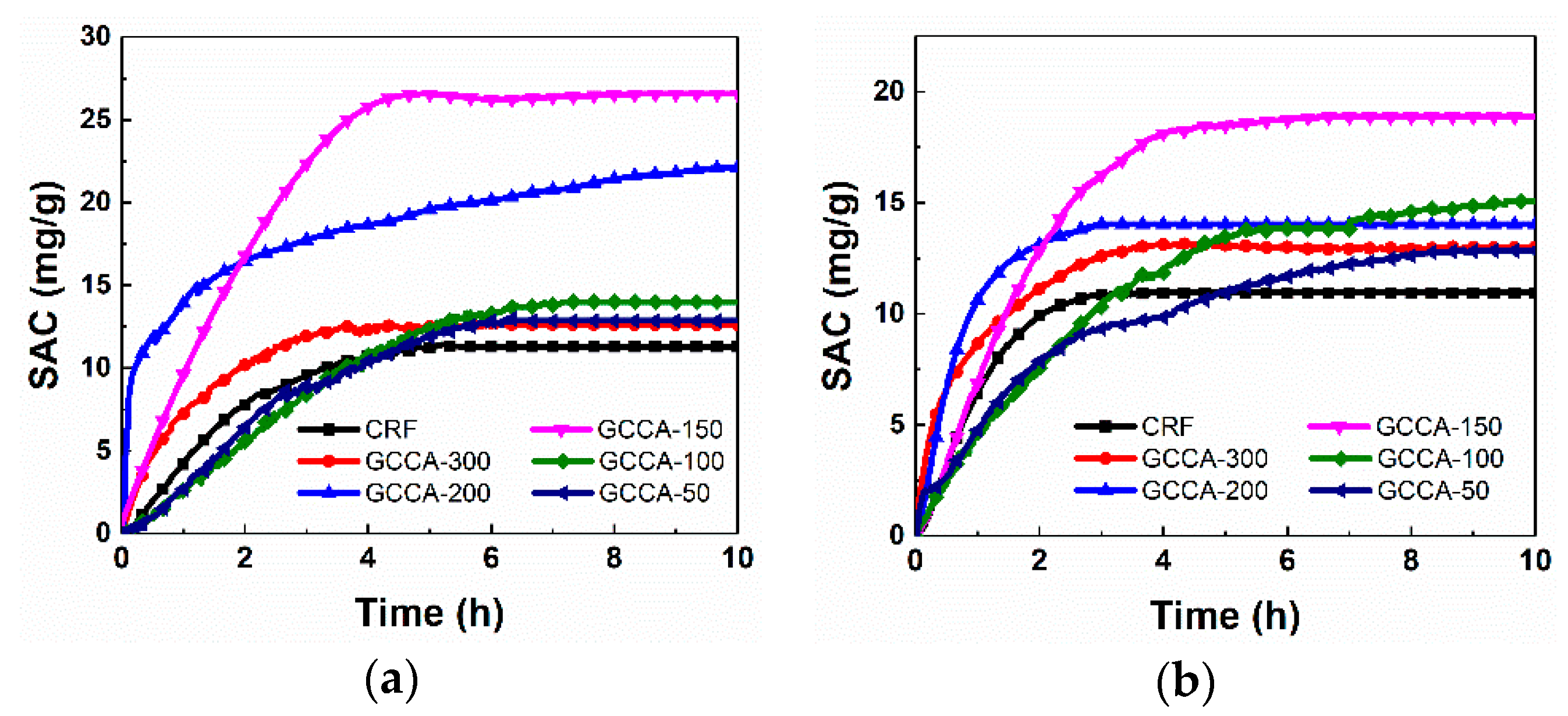
To evaluate the desalination capability of GCCA electrodes prepared with different RF/GO, CDI tests with batch mode were performed in NaCl solution with the initial concentrations of 500 mg/L and 250 mg/L, respectively. As shown in the Figure 6, the salt adsorption increases sharply once the electrodes are charged, and reach a maximum value after several hours, indicating the saturation of the electrodes. For both of the NaCl solutions with different initial concentrations, all these composite aerogel electrodes show larger SAC than that of CRF despite the CRF having the maximum SSA. With the decrease of RF/GO, the SAC of the GCCA electrode increases, and GCCA-150 exhibits the maximum SAC of 26.9 mg/g and 18.9 mg/g in 500 mg/L and 250 mg/L NaCl solutions, respectively. This benefits not only from the superior electrical conductivity of the graphene reduced by pyrolysis, but also from the good dispersion of the graphene sheets in the carbon matrix that form a uniform network. With the GO content increasing continuously, the SAC begins to drop, which may be caused by the low electrochemical response that leads to the increased barrier for ion transportation and the reduced pore volume due to the agglomeration of GO. Comparing the SAC results performed in the different concentrations of NaCl solutions, all the GCCA electrodes show lower SAC in 250 mg/L NaCl solution than that in 500 mg/L NaCl solution, which is mainly ascribed to the decrease of the ion concentration gradient which weakens the ion-transport rate surrounding the pores.
4. Conclusions
In summary, we successfully synthesized GCCAs with hierarchy configuration composed of randomly oriented graphene sheets and carbon nanoparticles using an ambient drying method. The self-assembly mechanism of GO nanosheets and RF molecules during the sol–gel process was discussed, and the microstructure of the obtained GCCAs can be tuned through changing the mass ratio of RF/GO in the starting mixture. Owing to the reasonable pore structure and highly conductive network, GCCA-150 exhibits decent electrochemical performance and the best electrosorption capacities of 26.9 mg/g in 500 mg/L and 18.9 mg/g in 250 mg/L NaCl solutions.
Author Contributions
Conceptualization, H.W.; Data curation, C.Z.; Formal analysis, X.W. (Xiaodong Wang) and X.W. (Xueling Wu); Investigation, C.Z. and X.W. (Xueling Wu); Methodology, H.W.; Resources, J.S.; Supervision, J.S.; Validation, X.W. (Xiaodong Wang) and J.S.; Writing—original draft, C.Z.; Writing—review & editing, X.W. (Xiaodong Wang).
Funding
The authors gratefully acknowledge the support from National Key Research and Development Program of China (2017YFA0204600), National Natural Science Foundation of China (11874288) and Fundamental Research Funds for the Central Universities of Tongji University.
Conflicts of Interest
The authors declare no conflict of interest.
References
- Farmer, J.C.; Fix, D.V.; Mack, G.V.; Pekala, R.W.; Poco, J.F. The use of capacitive deionization with carbon aerogel electrodes to remove inorganic contaminants from water. Off. Sci. Tech. Inf. Tech. Rep. 1995, 15, 595–599. [Google Scholar]
- Porada, S.; Zhao, R.; van der Wal, A.; Presser, V.; Biesheuvel, P.M. Review on the science and technology of water desalination by capacitive deionization. Prog. Mater. Sci. 2013, 58, 1388–1442. [Google Scholar] [CrossRef] [Green Version]
- Shannon, M.A.; Bohn, P.W.; Elimelech, M.; Georgiadis, J.G.; Mariñas, B.J.; Mayes, A.M. Science and technology for water purification in the coming decades. Nature 2008, 452, 301–310. [Google Scholar] [CrossRef] [PubMed]
- Humplik, T.; Lee, J.; O’Hern, S.C.; Fellman, B.A.; Baig, M.A.; Hassan, S.F.; Atieh, M.A.; Rahman, F.; Laoui, T.; Karnik, R. Nanostructured materials for water desalination. Nanotechnology 2011, 22, 292001. [Google Scholar] [CrossRef] [PubMed]
- AlMarzooqi, F.A.; Al Ghaferi, A.A.; Saadat, I.; Hilal, N. Application of Capacitive Deionisation in water desalination: A review. Desalination 2014, 342, 3–15. [Google Scholar] [CrossRef]
- Suss, M.E.; Porada, S.; Sun, X.; Biesheuvel, P.M.; Yoon, J.; Presser, V. Water desalination via capacitive deionization: What is it and what can we expect from it? Energy Environ. Sci. 2015, 8, 2296–2319. [Google Scholar] [CrossRef]
- Sui, Z.; Meng, Q.; Zhang, X.; Ma, R.; Cao, B. Green synthesis of carbon nanotube–graphene hybrid aerogels and their use as versatile agents for water purification. J. Mater. Chem. 2012, 22, 8767. [Google Scholar] [CrossRef]
- Yan, C.; Kanaththage, Y.W.; Short, R.; Gibson, C.T.; Zou, L. Graphene/Polyaniline nanocomposite as electrode material for membrane capacitive deionization. Desalination 2014, 344, 274–279. [Google Scholar] [CrossRef]
- Pasta, M.; Wessells, C.D.; Cui, Y.; La Mantia, F. A desalination battery. Nano Lett. 2012, 12, 839–843. [Google Scholar] [CrossRef]
- Porada, S.; Weingarth, D.; Hamelers, H.V.M.; Bryjak, M.; Presser, V.; Biesheuvel, P.M. Carbon flow electrodes for continuous operation of capacitive deionization and capacitive mixing energy generation. J. Mater. Chem. A 2014, 2, 9313–9321. [Google Scholar] [CrossRef]
- Dermentzis, K.; Wessner, W. Continuous capacitive deionization with regenerative rotating film electrodes. Electrochem. Commun. 2018, 92, 5–8. [Google Scholar] [CrossRef]
- Zou, L.; Morris, G.; Qi, D. Using activated carbon electrode in electrosorptive deionisation of brackish water. Desalination 2008, 225, 329–340. [Google Scholar] [CrossRef]
- Wang, L.; Wang, M.; Huang, Z.H.; Cui, T.; Gui, X.; Kang, F.; Wang, K.; Wu, D. Capacitive deionization of NaCl solutions using carbon nanotube sponge electrodes. J. Mater. Chem. 2011, 21, 18295–18299. [Google Scholar] [CrossRef]
- Tsouris, C.; Mayes, R.; Kiggans, J.; Sharma, K.; Yiacoumi, S.; DePaoli, D.; Dai, S. Mesoporous carbon for capacitive deionization of saline water. Environ. Sci. Technol. 2011, 45, 10243–10249. [Google Scholar] [CrossRef] [PubMed]
- Kumar, R.; Sen Gupta, S.; Katiyar, S.; Raman, V.K.; Varigala, S.K.; Pradeep, T.; Sharma, A. Carbon aerogels through organo-inorganic co-assembly and their application in water desalination by capacitive deionization. Carbon 2016, 99, 375–383. [Google Scholar] [CrossRef]
- Quan, X.; Fu, Z.; Yuan, L.; Zhong, M.; Mi, R.; Yang, X.; Yi, Y.; Wang, C. Capacitive deionization of NaCl solutions with ambient pressure dried carbon aerogel microsphere electrodes. RSC Adv. 2017, 7, 35875–35882. [Google Scholar] [CrossRef] [Green Version]
- Thamilselvan, A.; Nesaraj, A.S.; Noel, M. Review on carbon-based electrode materials for application in capacitive deionization process. Inter. J. Environ. Sci. Technol. 2016, 13, 2961–2976. [Google Scholar] [CrossRef]
- Liu, Y.; Nie, C.; Liu, X.; Xu, X.; Sun, Z.; Pan, L. Review on carbon-based composite materials for capacitive deionization. RSC Adv. 2015, 5, 15205–15225. [Google Scholar] [CrossRef]
- Jung, H.-H.; Hwang, S.-W.; Hyun, S.-H.; Lee, K.-H.; Kim, G.-T. Capacitive deionization characteristics of nanostructured carbon aerogel electrodes synthesized via ambient drying. Desalination 2007, 216, 377–385. [Google Scholar] [CrossRef]
- Zafra, M.C.; Lavela, P.; Rasines, G.; Macías, C.; Tirado, J.L.; Ania, C.O. A novel method for metal oxide deposition on carbon aerogels with potential application in capacitive deionization of saline water. Electrochim. Acta 2014, 135, 208–216. [Google Scholar] [CrossRef] [Green Version]
- Macías, C.; Lavela, P.; Rasines, G.; Zafra, M.C.; Tirado, J.L.; Ania, C.O. On the correlation between the porous structure and the electrochemical response of powdered and monolithic carbon aerogels as electrodes for capacitive deionization. J. Solid State Chem. 2016, 242, 21–28. [Google Scholar] [CrossRef]
- Du, A.; Zhou, B.; Zhang, Z.; Shen, J. A Special Material or a New State of Matter: A Review and Reconsideration of the Aerogel. Materials 2013, 6, 941–968. [Google Scholar] [CrossRef] [PubMed] [Green Version]
- Shen, J.; Hou, J.; Guo, Y.; Xue, H.; Wu, G.; Zhou, B. Microstructure Control of RF and Carbon Aerogels Prepared by Sol-Gel Process. J. Sol-Gel Sci. Technol. 2005, 36, 131–136. [Google Scholar] [CrossRef]
- Liu, N.P.; Shen, J.; Guan, D.Y.; Liu, D.; Zhou, X.W.; Li, Y.J. Effect of Carbon Aerogel Activation on Electrode Lithium Insertion Performance. Acta Phys.-Chim. Sin. 2013, 29, 966–972. [Google Scholar]
- Macías, C.; Rasines, G.; Lavela, P.; Zafra, M.C.; Tirado, J.L.; Ania, C.O. Mn-Containing N-Doped Monolithic Carbon Aerogels with Enhanced Macroporosity as Electrodes for Capacitive Deionization. ACS Sustain. Chem. Eng. 2016, 4, 2487–2494. [Google Scholar] [Green Version]
- Bai, Y.; Huang, Z.-H.; Yu, X.-L.; Kang, F. Graphene oxide-embedded porous carbon nanofiber webs by electrospinning for capacitive deionization. Colloid Surf. A 2014, 444, 153–158. [Google Scholar] [CrossRef] [Green Version]
- Geim, A.K.; Novoselov, K.S. The rise of graphene. Nat. Mater. 2007, 6, 183–191. [Google Scholar] [CrossRef]
- Guo, K.; Song, H.; Chen, X.; Du, X.; Zhong, L. Graphene oxide as an anti-shrinkage additive for resorcinol-formaldehyde composite aerogels. Phys. Chem. Chem. Phys. 2014, 16, 11603–11608. [Google Scholar] [CrossRef]
- Sun, W.; Du, A.; Gao, G.; Shen, J.; Wu, G. Graphene-templated carbon aerogels combining with ultra-high electrical conductivity and ultra-low thermal conductivity. Microporous Mesoporous Mater. 2017, 253, 71–79. [Google Scholar] [CrossRef]
- Dreyer, D.R.; Park, S.; Bielawski, C.W.; Ruoff, R.S. The chemistry of graphene oxide. Chem. Soc. Rev. 2009, 39, 228–240. [Google Scholar] [CrossRef]
- Wang, X.; Lu, L.L.; Yu, Z.L.; Xu, X.W.; Zheng, Y.R.; Yu, S.H. Scalable template synthesis of resorcinol-formaldehyde/graphene oxide composite aerogels with tunable densities and mechanical properties. Angew. Chem. Int. Ed. 2015, 54, 2397–2401. [Google Scholar] [CrossRef] [PubMed]
- Xia, X.-H.; Zhang, X.-F.; Yi, S.-Q.; Liu, H.-B.; Chen, Y.-X.; Chen, H.; Yang, L.; He, Y.-D. Preparation of high specific surface area composite carbon cryogels from self-assembly of graphene oxide and resorcinol monomers for supercapacitors. J. Solid State Electrochem. 2016, 20, 1793–1802. [Google Scholar] [CrossRef]
- He, S.; Chen, W. High performance supercapacitors based on three-dimensional ultralight flexible manganese oxide nanosheets/carbon foam composites. J. Power Sources 2014, 262, 391–400. [Google Scholar] [CrossRef]
- Rasines, G.; Lavela, P.; Macías, C.; Zafra, M.C.; Tirado, J.L.; Parra, J.B.; Ania, C.O. N-doped monolithic carbon aerogel electrodes with optimized features for the electrosorption of ions. Carbon 2015, 83, 262–274. [Google Scholar] [CrossRef] [Green Version]
- Li, S.M.; Yang, S.Y.; Wang, Y.S.; Lien, C.H.; Tien, H.W.; Hsiao, S.T.; Liao, W.H.; Tsai, H.P.; Chang, C.L.; Ma, C.C.M. Controllable synthesis of nitrogen-doped graphene and its effect on the simultaneous electrochemical determination of ascorbic acid, dopamine, and uric acid. Carbon 2013, 59, 418–429. [Google Scholar] [CrossRef]
- Terzyk, A.P. The influence of activated carbon surface chemical composition on the adsorption of acetaminophen (paracetamol) in vitro: Part II. TG, FTIR, and XPS analysis of carbons and the temperature dependence of adsorption kinetics at the neutral pH. Colloid Surf. A 2001, 177, 23–45. [Google Scholar] [CrossRef]
- Sun, W.; Gao, G.; Zhang, K.; Liu, Y.; Wu, G. Self-assembled 3D N-CNFs/V2O5 aerogels with core/shell nanostructures through vacancies control and seeds growth as an outstanding supercapacitor electrode material. Carbon 2018, 132, 667–677. [Google Scholar] [CrossRef]
- Liu, Y.; Guan, D.; Gao, G.; Liang, X.; Sun, W.; Zhang, K.; Bi, W.; Wu, G. Enhanced electrochemical performance of electrospun V2O5 nanotubes as cathodes for lithium ion batteries. J. Alloys Compd. 2017, 726, 922–929. [Google Scholar] [CrossRef]
Figure 1.
Raman spectra of GO, GCCA-150 and CRF (GO: graphene oxide; GCCA: graphene–composite carbon aerogel; CRF: pure carbon aerogel derived from the polycondensation of R and F).
Figure 1.
Raman spectra of GO, GCCA-150 and CRF (GO: graphene oxide; GCCA: graphene–composite carbon aerogel; CRF: pure carbon aerogel derived from the polycondensation of R and F).
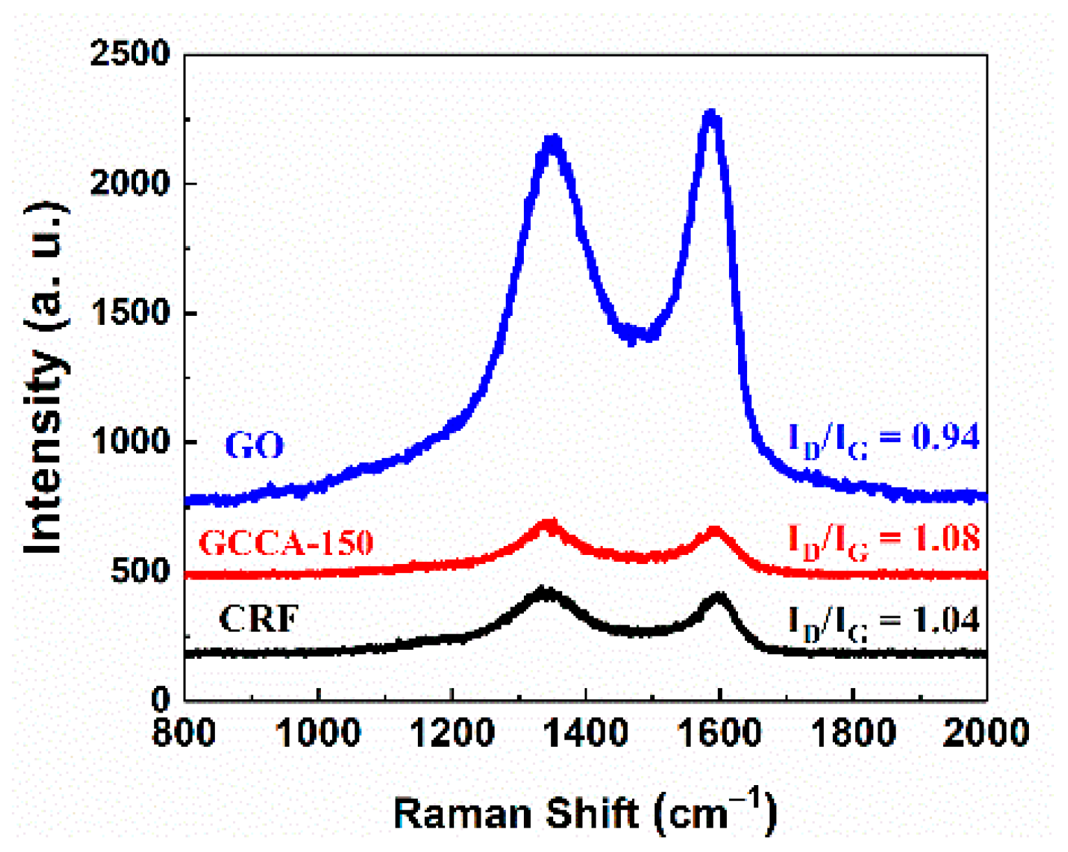
Figure 2.
X-ray photoelectron spectroscopy (XPS) spectra of the C 1s and O 1s for (a,b) CRF and (c,d) GCCA-150.
Figure 2.
X-ray photoelectron spectroscopy (XPS) spectra of the C 1s and O 1s for (a,b) CRF and (c,d) GCCA-150.

Figure 3.
Scanning electron microscope (SEM) images of (a) CRF; (b) GCCA-300; (c) GCCA-200; (d) GCCA-150; (e) GCCA-100; and (f) GCCA-50.
Figure 3.
Scanning electron microscope (SEM) images of (a) CRF; (b) GCCA-300; (c) GCCA-200; (d) GCCA-150; (e) GCCA-100; and (f) GCCA-50.

Figure 4.
(a) N2 adsorption–desorption isotherms at 77 K and (b) pore size distribution of CRF and different GCCAs.
Figure 4.
(a) N2 adsorption–desorption isotherms at 77 K and (b) pore size distribution of CRF and different GCCAs.

Figure 5.
(a) Cyclic voltammograms and (b) electrochemical impedance spectroscopy results of the CRF and GCCA electrodes.
Figure 5.
(a) Cyclic voltammograms and (b) electrochemical impedance spectroscopy results of the CRF and GCCA electrodes.
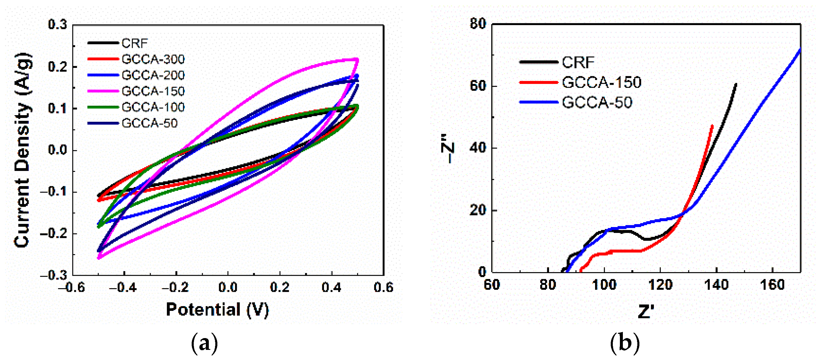
Figure 6.
Salt adsorption capacities for the CRF and GCCA electrodes in NaCl solution with the initial concentrations of (a) 500 mg/L and (b) 250 mg/L.
Figure 6.
Salt adsorption capacities for the CRF and GCCA electrodes in NaCl solution with the initial concentrations of (a) 500 mg/L and (b) 250 mg/L.

Table 1.
Pore structure parameters of CRF and GCCAs obtained from N2 adsorption measurement (CRF: pure carbon aerogel derived from the polycondensation of R and F; GCCAs: graphene–composite carbon aerogels).
Table 1.
Pore structure parameters of CRF and GCCAs obtained from N2 adsorption measurement (CRF: pure carbon aerogel derived from the polycondensation of R and F; GCCAs: graphene–composite carbon aerogels).
| Samples | SBET 1 (m2/g) | Smic (m2/g) | Vtot (cc/g) | Vmic (cc/g) | Vmic/Vtot (%) |
|---|---|---|---|---|---|
| CRF | 901.9 | 276.0 | 1.847 | 0.221 | 12.0 |
| GCCA-300 | 820.9 | 166.8 | 2.023 | 0.119 | 5.9 |
| GCCA-200 | 554.8 | 143.9 | 1.794 | 0.086 | 4.7 |
| GCCA-150 | 546.2 | 108.5 | 1.746 | 0.046 | 2.6 |
| GCCA-100 | 475.5 | 80.3 | 0.742 | 0.034 | 4.6 |
| GCCA-50 | 93.6 | 35.3 | 0.177 | 0.016 | 9.0 |
1 SBET: specific surface area (SSA) obtained using multi-point Brunauer–Emmett–Teller (BET) calculation; Smic, Vmic: micropore SSA and volume, respectively, obtained by t-plot calculation; Vtot: total pore volume.
© 2019 by the authors. Licensee MDPI, Basel, Switzerland. This article is an open access article distributed under the terms and conditions of the Creative Commons Attribution (CC BY) license (http://creativecommons.org/licenses/by/4.0/).
Share and Cite
MDPI and ACS Style
Zhang, C.; Wang, X.; Wang, H.; Wu, X.; Shen, J. Ambient Pressure-Dried Graphene–Composite Carbon Aerogel for Capacitive Deionization. Processes 2019, 7, 29. https://doi.org/10.3390/pr7010029
AMA Style
Zhang C, Wang X, Wang H, Wu X, Shen J. Ambient Pressure-Dried Graphene–Composite Carbon Aerogel for Capacitive Deionization. Processes. 2019; 7(1):29. https://doi.org/10.3390/pr7010029
Chicago/Turabian StyleZhang, Chen, Xiaodong Wang, Hongqiang Wang, Xueling Wu, and Jun Shen. 2019. "Ambient Pressure-Dried Graphene–Composite Carbon Aerogel for Capacitive Deionization" Processes 7, no. 1: 29. https://doi.org/10.3390/pr7010029
Note that from the first issue of 2016, this journal uses article numbers instead of page numbers. See further details here.