Evaluation of the Influences of Scrap Melting and Dissolution during Dynamic Linz–Donawitz (LD) Converter Modelling
by
 , ,
, ,
Florian Markus Penz
1,* ,
,
Johannes Schenk
1,2,
Rainer Ammer
3,
Gerald Klösch
4 and
Krzysztof Pastucha
5 1
K1-MET GmbH, Stahlstraße 14, A-4020 Linz, Austria
2
Chair of Ferrous Metallurgy, Montanuniversität Leoben, Franz Josef Straße 18, A-8700 Leoben, Austria
3
voestalpine Stahl GmbH, voestalpine Straße 3, A-4020 Linz, Austria
4
voestalpine Stahl Donawitz GmbH, Kerpelystraße 199, A-8700 Leoben, Austria
5
Primetals Technologies Austria GmbH, Turmstraße 44, A-4020 Linz, Austria
*
Author to whom correspondence should be addressed.
Processes 2019, 7(4), 186; https://doi.org/10.3390/pr7040186
Submission received: 22 February 2019
/
Revised: 26 March 2019
/
Accepted: 28 March 2019
/
Published: 31 March 2019
(This article belongs to the Special Issue Process Modelling and Simulation)
Abstract
:The Linz–Donawitz (LD) converter is still the dominant process for converting hot metal into crude steel with the help of technically pure oxygen. Beside hot metal, scrap is the most important charging material which acts as an additional iron source and coolant. Because of the irrevocable importance of the process, there is continued interest in a dynamic simulation of the LD process, especially regarding the savings of material and process costs with optimized process times. Based on a thermodynamic and kinetic Matlab® coded model, the influences of several scrap parameters on its melting and dissolution behavior were determined, with a special focus on establishing the importance of specific factors on the crude steel composition and bath temperature after a defined blowing period to increase the accuracy of the process model. The calculations reported clearly indicate that the dynamic converter model reacts very sensitively to the chemical composition of the scrap as well as the charged scrap mass and size. Those results reflect the importance of experiments for validation on the diffusive scrap melting model in further research work. Based on that, reliable conclusions could be drawn to improve the theoretical and practical description of the dissolution and melting behavior of scrap in dynamic converter modelling.

1. Introduction
The Linz–Donawitz (LD) converter steelmaking process was patented in Austria in the early 1950s. The invention of the LD converter enabled the refinement of hot metal to crude steel in short blowing periods of around 20 min, enabling the high productivity of the steelmaking industry today. Technically pure oxygen is blown onto the surface of the liquid melt inside the vessel, which leads to an increase of the reaction surface through the ejection of iron droplets and further to a stronger oxidation of the dissolved elements like carbon, silicon, manganese and phosphorus. These chemical reactions are exothermic, which results in a sharp temperature rise. As a coolant, steel scrap is added at the beginning of each blowing period [1,2,3,4,5].
As process and material costs are getting more important, the modelling of the process is crucial. Several authors gave different approaches for modelling the scrap melting during the LD converter process e.g., by Kruskopf in [6,7,8], Guo in [9] and Sethi and Shukla et al. in [10,11,12]. In previous publications by Y. Lytvynyuk et al. [13,14], a single reaction zone model was developed. This paper should point out the sensitivity of various scrap parameters on the simulation results. Therefore, the only parameters which will be changed are scrap parameters.
2. Description of the Dynamic LD Converter Model
Lytvynyuk’s model is based on thermodynamic and kinetic calculations [13,14]. It is assumed that in the heterogeneous thermodynamic reaction zone, all components can be conveyed between the slag and metal phases except carbon, which is oxidized to become gaseous carbon monoxide. The chemical oxidation reactions are assumed to be simultaneous at the interfacial surface between the slag and metal phases, whereby the oxidized carbon is removed instantly, and the equilibrium thermodynamics of the post combustion is neglected according to a non-reversible oxidation process. The flowsheet of the LD converter model is presented in Figure 1. Two simulation targets can be attained. During the main calculation loop, the mass and heat balances are calculated. Every single element is considered due to the results of chemical reactions, the consumption of the blown oxygen and the heating and melting of the charged materials. In the heat balance the consumed and generated heats are considered. Additionally, a structure of sub models will be solved during the main calculation loop. In this paper only the sub model of the scrap melting will be explained in detail. A more detailed description of the whole model is given in [4,13,15,16].
During the entire process, the chemical composition of the metal and slag phases changes due to the blowing oxygen consumption theory by V.E. Grum-Grzhimaylo for Bessemer converters [17]. In this theory, it is assumed that only iron is oxidized by blown oxygen and the remaining elements in the metal phase react with the iron oxide. The slag phase is formed by chemical reactions, melting and dissolution of charge materials and iron oxide, which is generated in the hot spot as a result of iron burning. Beside the oxidation, the dissolution and melting behavior of all charged materials influences the melt and slag composition during the entire blowing period. It is considered that the metal phase consists of the charged hot metal. Further, the solid scrap will be dissolved only in the hot metal due to its higher density. The other materials, which able to be charged, like lime, pellets, magnesia or dolomite, are assumed to dissolve only in the slag phase. They can be charged in portions during the heat [13,14].
The coupled reaction model published by Ohguchi et al. in [18] is used to describe the concurrent oxidation–reduction reactions between slag and metal, which is commonly utilized for the determination of the influence of kinetic parameters on chemical reaction rates and dephosphorization processes. [18,19,20,21,22,23,24,25]. In the present model, the simultaneous chemical reactions between the two different phases of the heterogeneous thermodynamic system can be determined by the system of chemical reactions listed in Equation (1). The reactions take place on the interfacial area between the slag and metal phase. Hess´s law is utilized for all calculated reactions. [13] In Equations (1) and (2) following metallurgical convention was used: [], () and {} indicate the metal, slag and gas phases, respectively.
For example, the oxidation of phosphorus by iron oxide is expressed by combining two reactions of Equation (1), which will result in Equation (2).
By the use of the system of the chemical reactions, any change of one component parameter, e.g., the concentration or the activity coefficient, will lead to a change in the whole system of the considered chemical reactions. [13,14,26].
The dynamic LD converter model used is mainly focused on cost reduction due to shorter process times and specified amounts of charged materials. This parameter study on scrap melting and dissolution behavior was performed since alterations in component parameters influence the whole system because of the thermodynamic and kinetic principles of the model and its equation of oxygen balance. For all mathematical and chemical expressions, the following assumptions were taken into account:
- At the interfacial surface all reactions are expeditious and equilibrated at each time step.
- The mass transfer kinetics in the metal and slag phases are the limitation for reaction rates.
The fundamental equation to solve the calculation is one algebraic equation, which includes the bulk chemical compositions of the metal and the slag phases as well as thermodynamic and kinetic parameters. The flowchart of the reaction model is given in Figure 2. Further descriptions of the kinetic and thermodynamic calculations and for the melting behavior of slag formers, pellets and FeSi were published by Lytvynyuk et al. [13,26].
To receive the effective equilibrium constant of the oxidation reaction as a result of the thermodynamic calculation, the equilibrium constants, as well as the activity coefficients of the hot metal components, and the slag components have to be determined. [26] Thus will result in Equation (3). The activity coefficients of the slag components are calculated by the collective electron theory described by Grigoryan et al. in [28] or Kolesnikova et al. in [29]. For the determination of the activity coefficients the Wagner–Lupis–Elliot method was chosen, published by Sigworth and Elliott in [30].
The equilibrium constant for example for the oxidation reaction of phosphorus was derived from Equation (4). [28]
The model of Lytvynyuk et al. was validated based on the output parameters of a commercial 170 t converter, which was published by Lytvynyuk et al. in [31]. The model was in a good agreement with the measured industrial data. The behavior of the temperature, the composition of the metal and slag phases, as well as the melting and dissolution of charge materials requires shutdowns during a converter heat. This kind of research is difficult to realize, due to the high costs incurred by the loss of production. The trends of the temperature or the off gas composition as well as the composition of the metal and slag phases is comparable by information from literature. Lytvynyuk also carried out a validation in this direction and could present in [14] and [31] a good agreement between the model and literature-based information.
3. Mechanisms of Scrap Melting in the LD Model
Two mechanisms describe the scrap melting and dissolution behavior in the LD model used. The scrap is charged into the vessel at the beginning of the process. The scrap geometry is assumed to be spherical. It is also possible to define the scrap to be cylindrical in shape, but in this case a melting only in radial direction can be simulated. Further, a manipulation of the overall surface of the scrap particle can be executed by introducing the form factor sphericity. The sphericity of a particle is defined as the ratio of the surface area of a sphere to the surface area of the particle, whereby the sphere has the same volume as the given particle. [32,33] In this work only a spherical shaped scrap is determined. A study on the differences between cylindrical, spherical and particles manipulated by the use of sphericity was published by the authors in [27] to give a first estimation on scrap melting behavior on the influence of heat balance. For simplification, it is assumed that the surface temperature of the scrap is equal to the hot metal temperature and that the scrap is heated up through thermal conduction. Due to the fact that the solid scrap is denser than hot metal, it assumed that the scrap is covered by liquid hot metal. Therefore, the influence of radiation can be neglected [1,4,34,35].
Forced or convective scrap melting appears if the melt temperature exceeds the melting point of the scrap and diffusive scrap melting occurs at temperatures below the scrap melt point. Forced scrap melting controls the scrap dissolution in the final stage of the LD converter process and the temperature difference between hot metal and scrap acts as the driving force. In this case, heat transfer determines the scrap melting [34,35]. Equation (5) characterizes the model for forced scrap melting of a spherical scrap particle:
The scrap particle´s radius is r in unit (m). The heat transfer coefficient in the metal phase is hmet in (W m−2 K−1) and the density of the scrap is ρscrap in (kg m−3). The latent heat of scrap melting is L in (J kg−1). THM and Tliq are the temperatures of the metal phase and the liquidus temperature of the scrap in (K) [13,31]. H(Tscrap) is the specific enthalpy of scrap at the actual temperature of the scrap surface and H(Tliq) is the specific enthalpy of the scrap melting point, both in (J kg−1) [4,27].
Equation (6) describes the diffusive melting of a spherical scrap particle, where the driving force is the difference of carbon concentration in the liquid phase and the scrap. It is strongly dependent on the mass transfer coefficient of the system. According to the binary Fe-Fe3C diagram, low carbon scrap has a higher melting point than hot metal, with around 4.5 wt.% of carbon. [3]
The mass transfer coefficient in the metal phase is kmet in (m s−1). Cscrap and CHM are the carbon concentrations in the scrap and hot metal in (wt.%). Cliq describes the carbon concentration on the liquidus line. The density of the liquid hot metal is ρliquid and of the scrap is ρscrap, both in (kg m−³) [3,27]. The values for the liquidus lines are approximated by a database of Fe-Fe3C-Si-Mn diagrams, generated by the FactSageTM FSstel database (licensed to Montanuniversität Leoben, Department Metallurgie; Version 7.1, ©Thermfact and GTT-Technologies, Montreal, Canada and Herzogenrath, Germany) [13,36].
The specific mixing power, which is created by bottom stirring and oxygen blowing, provides the basis for the mass transfer coefficient in the metal phase. The mass transfer coefficient is calculated through a function of the total mixing power including the bath depth, the converter geometry, position and geometry of the oxygen lance and the number of bottom-stirring nozzles as well as the flow rate of oxygen and bottom-stirring gas [14,26]. The heat transfer coefficient of the metal phase is defined by the function given in Equation (7), which is dependent on the specific mixing power [35]. According to Lytvynyuk et al. the total mixing power is a sum of the mixing power by top-blown oxygen and the mixing power by bottom-blown gas [13].
4. Simulation Parameters
Based on industrial materials and their chemical composition, the influence of small adjustments in carbon, phosphorus and silicon contents as well as the size and charged mass of scrap were investigated. The variations of the carbon and silicon contents were taken according to their quantity in scrap. The phosphorus content is rather small in common steels; still, through the scrap melting, small quantities of phosphorus are always delivered through to the liquid melt and may influence the final phosphorus content. The aim is to clarify the relevance of the obtained deviation in comparison to the adjustments to maintain the future focus on the detailed description of the melting and dissolution behavior of scrap in an LD converter. In particular, it is necessary to evaluate the sensitivity of the dynamic LD converter model on the adjusted charged scrap for further purposes.
The input parameters are listed in Table 1; Table 2. For modelling, a common rail steel grade was used. It has to be mentioned that the blowing time was fixed at 12.6 min and the amount of blown oxygen was also constant. Hot metal, scrap, solid LD slag and sand are charged at the beginning of the blowing period, whereby for simplification, only lime is charged stepwise during the entire process time. In Table 1, the initial composition, the charged mass and charging temperature of the hot metal and scrap are listed. The charged mass of scrap and the hot metal are constant for all investigations except when the scrap mass was modified.
The chemistry of the initial slag as well as their compositions and the amounts of the charged dust pellets, sand and the added lime are shown in Table 2.
The standard scrap parameters from Table 1 were adjusted to analyze the melting and dissolution behavior of scrap in the BOF process. The phosphorus content in the scrap is very low, at 0.013 wt.%. The adjustment of the phosphorus was therefore set only to a higher content than usual, for example, which can be found in weathering steel. The changed values are listed in Table 3 and their percentage relative adjustment in comparison to the standard scrap is noted. It is assumed that the shape of the scrap is a sphere, whereby the size is defined to be its radius.
5. Results and Discussion
This publication displays in the following illustrations of the scrap melting and dissolution behavior during the LD process with the aforementioned parameters. The calculated influence of the adjusted parameters is also shown by the trajectories of carbon, phosphorus and the melt temperature.
5.1. Influence on the Melting and Dissolution Behavior of Scrap
In Figure 3 and Figure 4, the dissolution and melting behavior of scrap is pointed out. Between minutes 8 and 10, a kink occurs in all figures, resulting from the change between diffusive and forced scrap melting. At this point, the melt temperature exceeds the melting temperature of the scrap. Under real process conditions, a smooth transition between the two melting mechanisms will take place. While the melting takes place under real conditions in the two-phase area between the solidus and liquidus lines, in this model, the assumption is used that the melting point of scrap is specific to the liquidus line [27].
It is illustrated in Figure 3 that the rate of diffusive melting is faster for higher carbon content in the scrap. In the model, the denominator of the logarithmic term in Equation (4) decreases, since the difference of %Cliq and %Cscrap becomes smaller in comparison to the standard case. A lower carbon content results in the opposite. Also, a higher silicon content in the scrap leads to faster diffusive melting. The effect of the higher silicon content is a decrease of %Cliq, which also reduces the value of the denominator of the logarithmic term in Equation (4). Changes in the phosphorus contents do not show a big difference, because they are already too small to influence the melting behavior of scrap.
In Figure 4, it is shown that low-dimension scrap melts a little bit slower in the initial phase of melting because of the higher cooling effect due to a higher specific surface. Once the low-dimension scrap is heated up—between minutes three and four—the melting of low dimension scrap accelerates. The complete melting time of the big dimension scrap with a radius of 0.12 m is higher; however, the time difference is about 1 min in comparison to the low dimension scrap with a radius of 0.08 m. It is obvious that the amount of scrap has an influence on the trajectories of melting behavior. There is a strong increase in the scrap melting of high scrap amounts shortly before the transition point between diffusive and forced scrap melting. This is explainable through Equation (6), where the logarithmic term increases in value. According to the increasing temperatures and decreasing carbon concentrations in the hot metal at this stage of the process, the denominator of the logarithm decreases faster than the numerator.
5.2. Influence on the Final Crude Steel Temperature
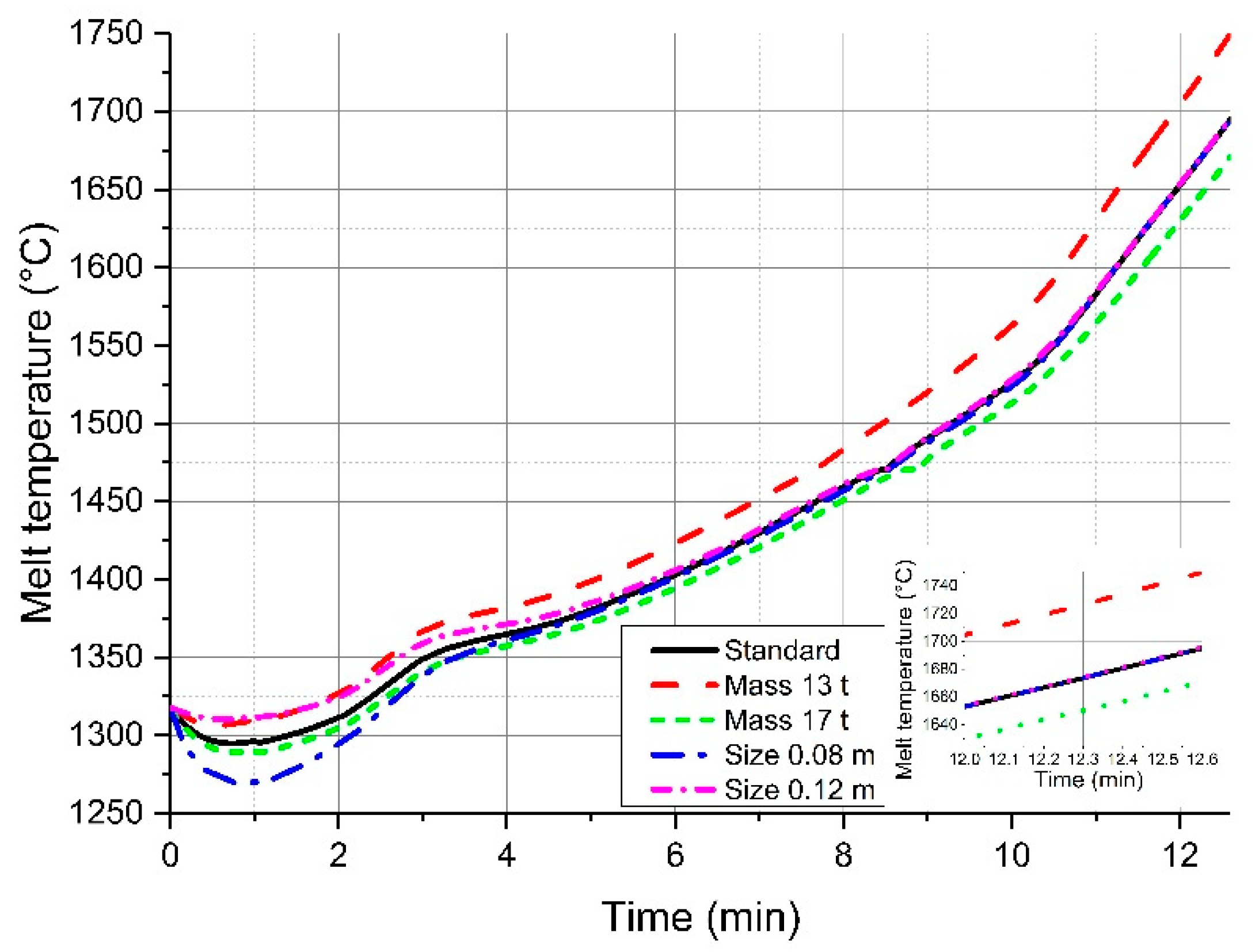
Influenced by the varying melting behavior, the calculated final temperature of the liquid crude steel changes slightly. As shown in Figure 5, the highest influence on the final temperature will be reached if the mass of charged scrap is modified. Due to the energy balance, less energy for heating the scrap will be needed with decreasing scrap amounts, which will result in higher tapping temperatures. But in comparison to the relative adjustments used, the influence on the final temperature is still small, whereby 1% means 16 °C.
The influence of the mass and the scrap size can be seen in Figure 6. It is obvious that a lower charged mass of scrap will consume less heat from the system, resulting in a higher final temperature. The variation of the scrap size will only influence the melt temperature in the initial stages of the blowing period. Due to the higher overall surface of small scale scrap (0.08 m in diameter) the exchange area of heat is increasing. This fact results in a higher cooling effect at the beginning of the blowing period.
5.3. Influence on the Final Carbon Content
Decarburization is one of the two main tasks of an LD converter. How strongly the calculated final carbon content is influenced by the assumed modifications is shown in Figure 7 and Figure 8. What is interesting to mention is that lower silicon contents in the scrap have a positive effect on decarburization and result in, besides low carbon contents in the scrap, lower final carbon contents in the liquid melt (Figure 7). In Figure 8, it is shown that a lower mass and therefore a lower input of carbon through scrap will also result in lower final values. The same behavior was determined for silicon. There is no large effect of the scrap size and the scrap phosphorus content on the final carbon content visible.
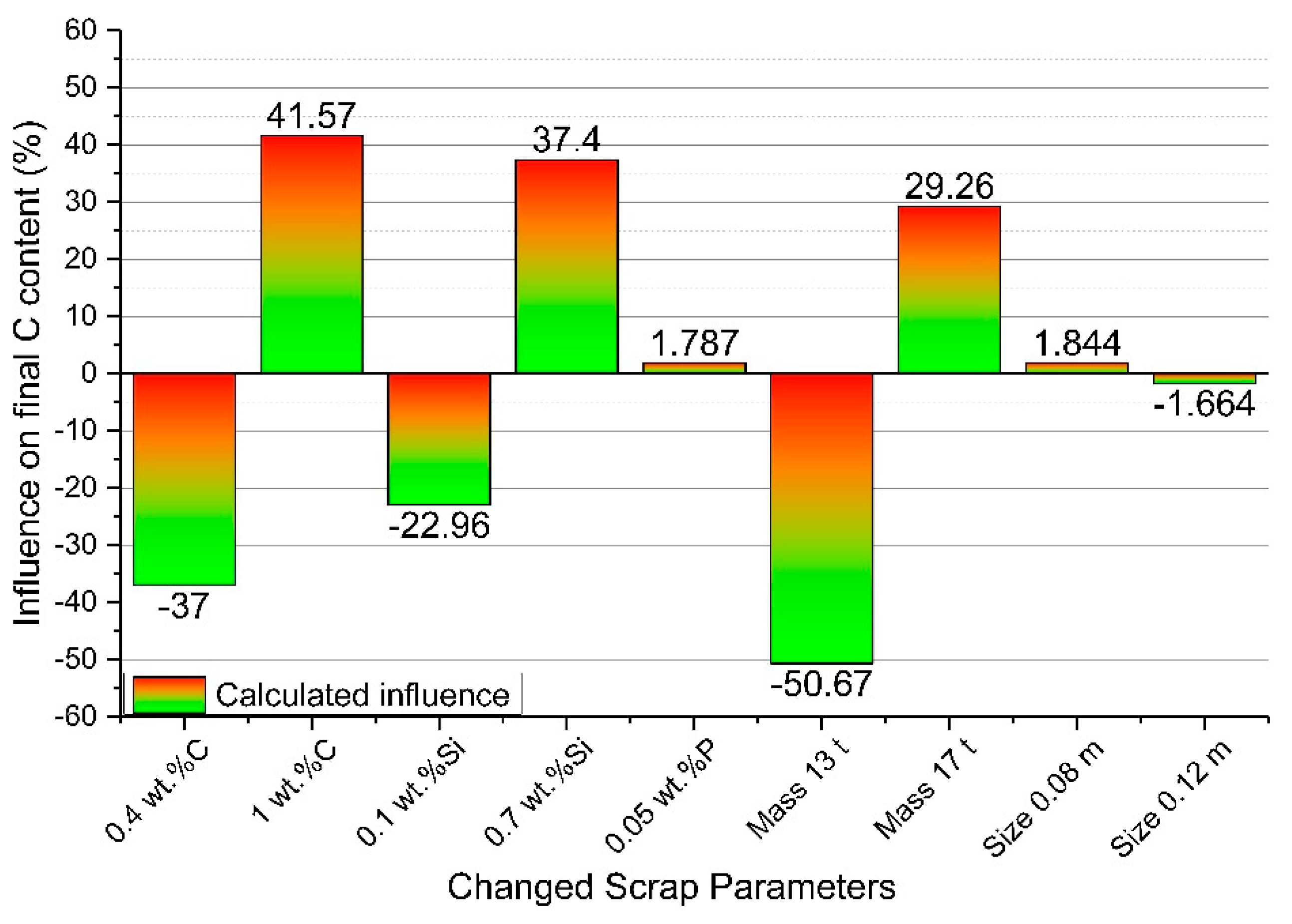
Even though the difference seems to be small in the final carbon content, it has to be carefully analyzed because a discrepancy of around 50% in the scrap carbon composition results in a final deviation of 40% in the final melt carbon composition. Similar values are detected in variations of the silicon content of the scrap and the scrap mass, as shown in Figure 9. A discrepancy in the final carbon composition of 50.67% was detected, if less scrap is charged. This high value results in the chosen rail scrap with a carbon content of 0.737 wt.%. Due to the faster melting of the reduced scrap mass, less carbon is transported into the melt and therefore lower amounts can be reached in the final content. The phosphorus content in the scrap and the particle size show no significant influence.
5.4. Influence on the Final Phosphorus Content
The second main task of an LD converter is dephosphorization, and the aim of each operator is to reach low phosphorus contents in the tapped crude steel. As shown in Figure 10 and Figure 11, the trajectories of the phosphorus content in the melt are influenced during the entire blowing period through the adjusted parameters. The interaction between an increasing amount of carbon, silicon and phosphorus in the scrap leads to higher final phosphorus contents in the tapped crude steel (Figure 10). Due to the still relatively high carbon activity and the increasing bath temperatures during the process, the stable oxides of manganese and phosphorus will be reduced. In the final stages of the blowing period, low amounts of carbon and silicon lead to an early carbon activity decrease. This results in an earlier resumption of the phosphorus oxidation.
Because of the strong influence on the melt temperature, the slag composition and the melting behavior of low-charged scrap amounts lead to higher calculated final phosphorus contents, as pointed out in Figure 11. In the main dephosphorization period at the beginning of the process, the temperature of the melt rises faster if there is less scrap or high volume scrap charged. Therefore, the point of re-phosphorization will start earlier and this causes higher final phosphorus contents in the melt. A possibility to counteract this behavior would be a different charging concept for lime and a modified slag metallurgy.
The percentage of influence on the final phosphorus content in the liquid melt according to the adjusted parameters is shown in Figure 12. It shows that the dynamic LD converter model reacts sensitively to the final phosphorus contents on variations in the chemical scrap composition and charged scrap mass.
6. Conclusions
The present study was done to clarify the relevance of the obtained deviations for the final temperature, composition and scrap melting behavior. Therefore, adjustments in chemical composition, size and mass of charged scrap were considered. The aim was to focus on the detailed description of the melting and dissolution behavior of scrap during the LD converter process for future work. The BOF model used was coded in MatLab® (R2014b, MathWorks Inc., Natick, MA, USA) and describes the behavior of the metal and slag phases during the blowing period of the BOF process using thermodynamic and kinetic equations.
The LD converter model used includes literature-based scrap melting equations. In the literature they are discussed, but insufficient validation reports are available. The model calculations show that around three quarters of the blowing process are dominated by diffusive scrap melting. A faster melting of the scrap could be indicated if the carbon or silicon content of the scrap were increased in comparison to the standard composition. This behavior is based on a lower melting point of scrap due to the higher contents of those elements. In this research, the phosphorus content of the scrap was also investigated. It has to be mentioned that it has no influence on the melting behavior of the scrap, but with increasing phosphorus in the scrap, the final phosphorus content in the liquid crude steel will also increase. It was shown that the amount of charged material has a very strong influence on the melting behavior as well as the final compositions of carbon and phosphorus. The scrap size changes those values solely in a small frame. It is worth pointing out that particularly low contents of carbon and silicon in the scrap also lower the final phosphorus and carbon content in the melt.
To sum up, the calculations reported in this paper clearly indicate that the dynamic BOF model reacts very sensitively to the chemical composition of the scrap as well as the charged scrap mass and size and therefore, the whole melting and dissolution behavior of scrap. Experiments will be necessary for validation of the diffusive scrap melting model. Based on that, reliable conclusions could be drawn to improve the theoretical and practical description of the dissolution and melting behavior of scrap. This description should be as precise as possible if it is necessary to be able to implement a complete dynamic LD converter model for usage in the industry.
Author Contributions
Conceptualization, F.M.P.; Data curation, F.M.P.; Investigation, F.M.P.; Methodology, F.M.P.; Project administration, F.M.P., J.S. and K.P.; Resources, F.M.P.; Software, F.M.P.; Supervision, F.M.P. and J.S.; Validation, J.S., R.A., G.K. and K.P.; Visualization, F.M.P.; Writing—original draft, F.M.P.; Writing—review & editing, F.M.P., J.S., R.A., G.K. and K.P.
Funding
This research project is co-funded by public financial resources from the Austrian Competence Center Programme COMET and by the industrial partners voestalpine Stahl, voestalpine Stahl Donawitz, and Primetals Technologies Austria.
Acknowledgments
The authors gratefully acknowledge the funding support of K1-MET GmbH, metallurgical competence center. The research programme of the K1-MET competence centre is supported by COMET (Competence Centre for Excellent Technologies), the Austrian programme for competence centres. COMET is funded by the Federal Ministry for Transport, Innovation and Technology, the Federal Ministry for Science, Research and Economy, the provinces of Upper Austria, Tyrol and Styria as well as the Styrian Business Promotion Agency (SFG).
Conflicts of Interest
The authors declare no conflict of interest.
References
- Turkdogan, E.T. Fundamentals of Steelmaking; The Institute of Materials: London, UK, 1996; pp. 209–244. [Google Scholar]
- Ghosh, A.; Chatterjee, A. Ironmaking and Steelmaking Theory and Practice; PHI Learning Private Limited: Delhi, India, 2015; pp. 285–292. [Google Scholar]
- Chigwedu, C. Beitrag zur Modellierung des LD-Sauerstoffaufblasverfahrens zur Stahlerzeugung. Ph.D. Thesis, Technische Universität Clausthal, Clausthal-Zellerfeld, Germany, 1997. [Google Scholar]
- Penz, F.M.; Bundschuh, P.; Schenk, J.; Panhofer, H.; Pastucha, K.; Paul, A. Effect of Scrap Composition on the Thermodynamics of Kinetic Modelling of BOF Converter. In Proceedings of the 2nd VDEh-ISIJ-JK Symposium, Stockholm, Sweden, 12–13 June 2017; pp. 124–135. [Google Scholar]
- Hiebler, H.; Krieger, W. Die Metallurgie des LD-Prozesses. BHM 1992, 137, 256–262. [Google Scholar]
- Kruskopf, A.; Holappa, L. Scrap melting model for steel converter founded on interfacial solid/liquid phenomena. Metall. Res. Technol. 2018, 115, 201–208. [Google Scholar] [CrossRef]
- Kruskopf, A.; Louhenkilpi, S. 1-Dimensional scrap melting model for steel converter (BOF). In Proceedings of the METEC & 2nd ESTAD, Düsseldorf, Germany, 15–19 June 2015; pp. 1–4. [Google Scholar]
- Kruskopf, A. A Model for Scrap Melting in Steel Converter. Metall. Mater. Trans. B 2015, 46, 1195–1206. [Google Scholar] [CrossRef]
- Guo, D.; Swickard, D.; Alavanja, M.; Bradley, J. Numerical Simulation of Heavy Scrap Melting in BOF steelmaking. Iron Steel Technol. 2013, 10, 125–132. [Google Scholar]
- Sethi, G.; Shukla, A.K.; Das, P.C.; Chandra, P.; Deo, B. Theoretical Aspects of Scrap Dissolution in Oxygen Steelmaking Converters. In Proceedings of the AISTech, Nashville, TN, USA, 15–17 September 2004; Volume II, pp. 915–926. [Google Scholar]
- Shukla, A.K.; Deo, B. Coupled heat and mass transfer approach to simulate the scrap dissolution in steelmaking process. In Proceedings of the International Symposium for Research Scholars on Metallurgy, Materials Science & Engineering, Chennai, India, 18–20 December 2006; pp. 1–14. [Google Scholar]
- Shukla, A.K.; Deo, B.; Robertson, D. Scrap Dissolution in Molten Iron Containing Carbon for the Case of Coupled Heat and Mass Transfer Control. Metall. Mater. Trans. B 2013, 44, 1407–1427. [Google Scholar] [CrossRef]
- Lytvynyuk, Y.; Schenk, J.; Hiebler, M.; Sormann, A. Thermodynamic and Kinetic Model of the Converter Steelmaking Process. Part 1: The Description of the BOF Model. Steel Res. Int. 2014, 85, 537–543. [Google Scholar] [CrossRef]
- Lytvynyuk, Y. Thermodynamic and Kinetic Modelling of Metallurgical Processes. Ph.D. Dissertation, Montanuniversität Leoben, Leoben, Austria, 2013. [Google Scholar]
- Hirai, M.; Tsujino, R.; Mukai, T.; Harada, T.; Masanao, O. Mechanism of Post Combustion in the Converter. Trans. ISIJ 1987, 27, 805–813. [Google Scholar] [CrossRef]
- Bundschuh, P.; Schenk, J.; Hiebler, M.; Panhofer, H.; Sormann, A. Influence of CaO Dissolution on the Kinetics of Metallurgical Reactions in BOF-process. In Proceedings of the 7th European Oxygen Steelmaking Conference, Trinec, Czech Republic, 9–11 September 2014. [Google Scholar]
- Boychenko, B.; Okhotskiy, V.; Kharlashin, P. The Converter Steelmaking; Dnipro-VAL: Dnipropetrovsk, Ukraine, 2006; pp. 22–69. [Google Scholar]
- Ohguchi, S.; Robertson, D.; Deo, B.; Grieveson, P.; Jeffes, J. Simultaneous dephosphorization and desulphurization of molten pig iron. Iron Steelmak. 1984, 11, 202–213. [Google Scholar]
- Kitamura, S.; Kitamura, T.; Shibata, K.; Mizukami, Y.; Mukawa, S.; Nakagawa, J. Effect of stirring energy, temperature and flux composition on hot metal dephosphorization kinetics. ISIJ Int. 1991, 31, 1322–1328. [Google Scholar] [CrossRef]
- Kitamura, S.; Kitamura, T.; Aida, T.; Sakomura, E.; Koneko, R.; Nuibe, T. Development of analyses and control method for hot metal dephosphorization process by computer simulation. ISIJ Int. 1991, 31, 1329–1335. [Google Scholar] [CrossRef]
- Kitamura, S.; Shibata, H.; Maruoka, N. Kinetic Model of Hot Metal Dephosphorization by Liquid and Solid coexisting slags. Steel Res. Int. 2008, 79, 586–590. [Google Scholar] [CrossRef]
- Pahlevani, F.; Kitamura, S.; Shibata, H.; Maruoka, N. Kinetic Model Dephosphorization in Converter. In Proceedings of the SteelSim, Leoben, Austria, 8–10 September 2009. [Google Scholar]
- Mukawa, S.; Mizukami, Y. Effect of stirring energy and rate of oxygen supply on the rate of hot metal dephosphorization. ISIJ Int. 1995, 35, 1374–1380. [Google Scholar] [CrossRef]
- Ishikawa, M. Analysis of hot metal desiliconization behaviour in converter experiments by coupled reaction model. ISIJ Int. 2004, 44, 316–325. [Google Scholar] [CrossRef]
- Higuchi, Y.; Tago, Y.; Takatani, K.; Fukagawa, S. Effect of stirring and slag condition on reoxidation on molten steel. ISIJ 1998, 84, 13–18. [Google Scholar]
- Lytvynyuk, Y.; Schenk, J.; Hiebler, M.; Mizelli, H. Thermodynamic and kinetic modelling of the devanadization process in the steelmaking converter. In Proceedings of the 6th European Oxygen Steelmaking Conference, Stockholm, Sweden, 7–9 September 2011. [Google Scholar]
- Penz, F.M.; Bundschuh, P.; Schenk, J.; Panhofer, H.; Pastucha, K.; Maunz, B. Scrap melting in BOF: Influence of particle surface and size during dynamic converter modelling. In Proceedings of the 3rd ABM week, São Paulo, Brazil, 2–6 October 2009. [Google Scholar]
- Grigoryan, A.H.; Stomakhin, A.J.; Ponomarenko, A.G. Physico-Chemical Calculations of the Electric Steel Process; Metallurgy: Moscow, Russia, 1989. [Google Scholar]
- Kolesnikova, K.; Gogunskii, V.; Olekh, T. Calculation of equilibrium in the system metal-slag during steelmaking in electric arc furnace. Metall. Min. Ind. 2016, 6, 8–13. [Google Scholar]
- Sigworth, G.K.; Elliot, J.F. The thermodynamics of liquid dilute iron alloys. Met. Sci. 1974, 8, 298–310. [Google Scholar] [CrossRef]
- Lytvynyuk, Y.; Schenk, J.; Hiebler, M.; Sormann, A. Thermodynamic and Kinetic Model of the Converter Steelmaking Process. Part 2: The Model Validation. Steel Res. Int. 2014, 85, 544–563. [Google Scholar] [CrossRef]
- Wadell, H. Volume, shape, and roundness of quartz particles. J. Geol. 1935, 43, 250–280. [Google Scholar] [CrossRef]
- Penz, F.M. Charakterisierung des Hochofeneinsatzstoffes Sinter, Mittels Optischer 3D-Partikelanalyse. Bachelor’s Thesis, Montanuniversitaet Leoben, Leoben, Austria, 2014. [Google Scholar]
- Medhibozhskiy, M.Y. Basis of Thermodynamic and Kinetic of Steelmaking; Vischa shkola: Kyiv, Ukraine, 1979; p. 229. [Google Scholar]
- Isobe, K.; Maede, H.; Ozawa, K.; Umezawa, K.; Saito, C. Analysis of the Scrap Melting Rate in High Carbon Molten Iron. ISIJ 1990, 76, 2033–2040. [Google Scholar] [Green Version]
- Zarl, M. Development and Evaluation of a BOF Pre-Processor Model. Master’s Thesis, Montanuniversität Leoben, Leoben, Austria, 2017. [Google Scholar]
Figure 1.
Flow sheet of the Linz–Donawitz (LD) converter model.

Figure 2.
Flowsheet of the reaction model used [14].
Figure 2.
Flowsheet of the reaction model used [14].

Figure 3.
Influence of adjustment on chemical composition on the melting behavior of scrap.

Figure 4.
Influence of variable charging scrap amounts and scrap size on the melting behavior.

Figure 5.
Influence on the final melt temperature; 1% defines a difference of 16 °C.

Figure 6.
Influence of variable charging scrap amounts and scrap size on the melt temperature.

Figure 7.
Influence of variable carbon and silicon contents on the carbon content of the liquid crude steel.
Figure 7.
Influence of variable carbon and silicon contents on the carbon content of the liquid crude steel.

Figure 8.
Influence of variable charging scrap amounts and scrap size on the carbon content of the liquid crude steel.
Figure 8.
Influence of variable charging scrap amounts and scrap size on the carbon content of the liquid crude steel.

Figure 9.
Calculated influence on the final carbon content.

Figure 10.
Influence of variable element contents in scrap on the phosphorus content of the liquid crude steel.
Figure 10.
Influence of variable element contents in scrap on the phosphorus content of the liquid crude steel.

Figure 11.
Influence of variable charging scrap amounts and scrap size on the phosphorus content of the liquid crude steel.
Figure 11.
Influence of variable charging scrap amounts and scrap size on the phosphorus content of the liquid crude steel.

Figure 12.
Calculated influence on the final phosphorus content.


Table 1.
Charging parameters of the hot metal and the standard scrap used.
| Definition | Unit | Hot Metal | Standard Scrap |
|---|---|---|---|
| Carbon content | wt.% | 4.536 | 0.737 |
| Silicon content | wt.% | 0.410 | 0.349 |
| Manganese content | wt.% | 1.171 | 1.060 |
| Phosphorus content | wt.% | 0.100 | 0.013 |
| Iron content | wt.% | 93.783 | 97.841 |
| Mass | t | 53.60 | 15.72 |
| Temperature | °C | 1318 | 20 |
Table 2.
Selected chemistry of added slag, sand and lime.
| Name | Unit | Initial Slag | Dust Pellets | Sand | Lime |
|---|---|---|---|---|---|
| SiO2 content | wt.% | 11.32 | - | 92.79 | 0.980 |
| MnO content | wt.% | 11.93 | 2.960 | - | - |
| P2O5 content | wt.% | 1.330 | - | - | - |
| FeO content | wt.% | 29.66 | - | - | - |
| CaO content | wt.% | 40.08 | 7.320 | - | 92.37 |
| MgO content | wt.% | 4.380 | 4.580 | - | 3.080 |
| CO2 content | wt.% | - | - | - | 2.400 |
| H2O content | wt.% | - | - | - | 0.170 |
| Fe2O3 content | wt.% | - | 67.88 | - | - |
| Fe content | wt.% | - | 11.09 | - | - |
| Amount of charged material | t | 0.001 | 1.000 | 0.172 | 2.800 |
Table 3.
Variation of the initial parameters of the scrap and their percentage.
| Name and Unit | Standard Scrap | Lower Value | Higher Value | ||
|---|---|---|---|---|---|
| Carbon content (wt.%) | 0.7370 | 0.40 | −45.7% | 1.00 | 35.68% |
| Silicon content (wt.%) | 0.3488 | 0.10 | −71.3% | 0.70 | 100.7% |
| Phosphorus content (wt.%) | 0.0130 | - | - | 0.05 | 273.1% |
| Size (m) | 0.1 | 0.08 | −20.0% | 0.12 | 20.00% |
| Mass (t) | 15.72 | 13.0 | −17.3% | 17.0 | % |
© 2019 by the authors. Licensee MDPI, Basel, Switzerland. This article is an open access article distributed under the terms and conditions of the Creative Commons Attribution (CC BY) license (http://creativecommons.org/licenses/by/4.0/).
Share and Cite
MDPI and ACS Style
Penz, F.M.; Schenk, J.; Ammer, R.; Klösch, G.; Pastucha, K. Evaluation of the Influences of Scrap Melting and Dissolution during Dynamic Linz–Donawitz (LD) Converter Modelling. Processes 2019, 7, 186. https://doi.org/10.3390/pr7040186
AMA Style
Penz FM, Schenk J, Ammer R, Klösch G, Pastucha K. Evaluation of the Influences of Scrap Melting and Dissolution during Dynamic Linz–Donawitz (LD) Converter Modelling. Processes. 2019; 7(4):186. https://doi.org/10.3390/pr7040186
Chicago/Turabian StylePenz, Florian Markus, Johannes Schenk, Rainer Ammer, Gerald Klösch, and Krzysztof Pastucha. 2019. "Evaluation of the Influences of Scrap Melting and Dissolution during Dynamic Linz–Donawitz (LD) Converter Modelling" Processes 7, no. 4: 186. https://doi.org/10.3390/pr7040186
Note that from the first issue of 2016, this journal uses article numbers instead of page numbers. See further details here.