A Cooperative Control Scheme for AC/DC Hybrid Autonomous Microgrids


1
China Electric Power Research Institute, Beijing 100192, China
2
School of Electrical Engineering, Southeast University, Nanjing 210096, China
*
Author to whom correspondence should be addressed.
Processes 2020, 8(3), 311; https://doi.org/10.3390/pr8030311
Submission received: 11 February 2020
/
Revised: 29 February 2020
/
Accepted: 5 March 2020
/
Published: 7 March 2020
(This article belongs to the Special Issue Energy Storage System: Integration, Power Quality, and Operation)
Abstract
:The AC/DC hybrid microgrid (MG) has been widely promoted due to its high flexibility. The capability to operate in islanding mode is an appealing advantage of the MG, and also sets higher requirements for its control system. A droop control strategy is proposed on account of its distinguishing feature of automatic power sharing between distributed generations (DGs), but it introduces some drawbacks. Therefore, distributed cooperative secondary control is introduced as an improvement. In order to optimize the active power sharing in AC/DC hybrid microgrids, a number of cooperative control strategies have been proposed. However, most studies of AC/DC hybrid microgrids have mainly focused on the control of the bidirectional converter, ignoring the effects of secondary control within subnets, which may make a difference to the droop characteristic. This paper extends the cooperative control to AC/DC hybrid microgrids based on normalizing and synthesizing the droop equations, and proposes a global cooperative control scheme for AC/DC autonomous hybrid microgrids, realizing voltage restoration within AC and DC subnets as well as accurate global power sharing. Ultimately, the simulation results demonstrate that the proposed control scheme has a favorable performance in the test AC/DC hybrid system.
1. Introduction
For the sake of improving the capacity of the power grid to penetrate distributed generations (DGs) as well as promoting the intelligent process of the grid, the concept of a microgrid (MG) has been put forward. As one of the typical structures of a MG, an AC/DC hybrid microgrid has been widely applied as it integrates the superiority of AC and DC systems [1] and has a flexible topology as well as diverse operation modes [2]. Compared with traditional power grids, the capability to operate in islanding mode is a unique advantage of MGs. When a planned or spontaneous event leads to the off−grid of a MG, it can still work in an autonomous state, but at this point, no external power grid can provide reference for the system frequency and voltage of the point of common coupling (PCC), setting higher requirements for the control system. Droop control is widely adopted in islanded MGs and can realize the capability of their plug and play. However, only depending on droop control may cause voltage deviation due to its deviating regulation characteristics. In addition, the differences of impedance between DGs and the PCC may lead to inappropriate power sharing, and sometimes even result in power circulation between DGs.
In order to eliminate the influence of unbalanced impedance and ensure high efficiency of the power grid, a large number of studies have adopted a hierarchical control strategy, introducing cooperative secondary control on the basis of primary control. The traditional centralized control [3,4] can realize the global optimization of MG effectively, but the high communication cost and low reliability in complex systems limit its development [5]. The proposal of the distributed control scheme [6,7] can effectively reduce the scale of data transmission, so as to realize the global control of the complex system with low communication cost. Dehkordi et al. [8] proposed a complete hierarchical control strategy for AC microgrids and Chunxia Dou et al. [9] designed a superior distributed cooperative controller for DC microgrids with commendable dynamic performance. Fanghong Guo et al. [10] designed an efficient secondary controller with the superiority of less information transmission and demonstrated its excellent performance in DC microgrids. These above−mentioned studies only focused on one separate microgrid, while the control of hybrid microgrids needs to consider the coordination between AC and DC systems, which will be more complex [11]. Considering that the fluctuation of transmission power may pose a threat to the system stability, constructing an appropriate control scheme for a bidirectional AC/DC converter to determine a befitting power flow is of great significance. Yu Ji et al. and Wenyan Hu et al. [12,13] both proposed a control method for the bidirectional converter, while they expressed the imbalance of power sharing indirectly by the deviation of voltage and frequency rather than establish a direct relationship between the active power of AC and DC subnets, thus may bring about inaccurate power sharing with the participation of secondary control within subnets. Xialin Li et al. [14] analyzed the operation mode of the bidirectional converter in different scenarios roundly and generalized the control method. Junjun Wang et al. [15] put forward a unified control scheme for the bidirectional converter adaptive in various scenarios and eliminated potential negative effects of a mode switch.
To summarize, few studies have given consideration to the coordination within and between subnets simultaneously. Most of them have focused on the secondary control within subnets [8,9,10] or the cooperative control between AC and DC systems [14,15] solely, ignoring the interaction between them. Nevertheless, they both exert an impact on the system operating state, where secondary control within subnets shifts the droop curves, while cooperative control between systems alters the position of the operating point on the droop curve, which in turn affects their respective controller inputs. Furthermore, the direct power sharing principle in AC/DC hybrid systems has received little concern.
This paper extends the distributed cooperative control to AC/DC hybrid microgrids based on normalizing and synthesizing the droop equations, establishes the power sharing relationship between the subnets and proposes a control strategy for the AC/DC autonomous microgrid. A hierarchical control strategy is adopted in AC and DC subnets. The primary control adopts droop control and the secondary control is introduced to implement voltage restoration and proportional power sharing between DGs. In addition, the controller of the bidirectional converter compares the power demand on AC and DC sides to determine the reference of transmission power. The simulation results on MATLAB/Simulink demonstrate that the proposed control scheme has a favorable performance in the test AC/DC hybrid system.
2. Basic Control Theory of the Microgrid
2.1. Configuration of AC/DC Hybrid Microgrids
The typical structure of an AC/DC hybrid microgrid is displayed in Figure 1. It mainly consists of the AC subnet, DC subnet and a bidirectional AC/DC converter connecting them [16]. Generally, DGs and load are contained in an MG, and a PCC represents the connection between the MG and the power grid.
2.2. Primary Droop Control
In the equation, , are the voltage and frequency reference of the droop control respectively; , are the no−load reference of frequency and voltage respectively; m and n are the frequency and voltage droop coefficient; P and Q are the average active power and reactive power respectively. In addition, subscripts ac and dc represent variables of AC and DC sides respectively.
For the purpose of proportional sharing of power between DGs according to their rated capacity, the selection of droop coefficient should satisfy the following equation:
where , , represent the frequency, voltage droop coefficient and rated capacity of the ith DG respectively, i = 1,2...k.
In practical operation, accurate power sharing and voltage restoration cannot be achieved by simply relying on droop control.
2.3. Cooperative Secondary Control
The secondary control in AC microgrids aims at realizing proportional reactive power sharing as well as voltage restoration. To achieve this objective, the setpoints of voltage and frequency reference are adjusted by adding a correction term. The correction term is composed of two parts, the voltage restoration correction term and the reactive power sharing adjustment correction term.
The voltage restoration loop expects to restore the average voltage to the rated value, and the corresponding input of the controller is the voltage deviation:
where is the nominal AC voltage.
The reactive power of DGs should satisfy the equation [18] for proportional sharing. The corresponding input of the reactive power sharing loop is:
where is the communication weight between the ith and jth inverters, and if there is no information exchange between the ith and jth inverters, is set to 0.
The integral controller is usually adopted in the secondary control, and the correction term for reference voltage is finally obtained as:
where represents the integral coefficient, and C represents the bias factor, which is related to the mismatch degree of voltage and reactive power sharing [19].
The modified reference value of droop voltage under cooperative secondary control is shown as (8), which is equivalent to shifting the voltage droop control curve:
The cooperative control strategy of the DC subnet is similar to that of the AC subnet, except that the DC system focuses on active power sharing rather than reactive power. Similarly, the ideal equation between the output active power of the converters is , and the corresponding input of the power sharing loop is:
The remainder of the control strategy is the same as that of the AC microgrid.
3. Cooperative Control Strategy of the AC/DC Converter
The cooperative secondary control strategy in MG commendably solves the problem of power sharing between DGs within AC and DC subnets, while the problem of inaccurate power sharing between AC and DC subnets still exists, the case that one side is overloaded while the other side assumes light load is of common occurrence. In order to avoid this phenomenon, this part extends the above cooperative control strategy and introduces AC/DC cooperative control to optimize the active power flow of bidirectional converters, so as to coordinate the output active power of DGs on different sides and make AC and DC subnets share active load according to their capacity.
3.1. Control Theory
The output active power of DGs on the AC side is closely related to the frequency, while that on the DC side is mainly affected by voltage. Figure 2 displays the initial −, − droop control curves in the AC and DC subnets.
In the figure, , , and represent the maximum and minimum AC frequency and DC voltage allowed in normal operation of the system respectively; and are the maximum output active power of DGs. Since the reference and variation range of AC frequency and DC voltage are different, firstly, the frequency and voltage are normalized to the same scale by (10) and (11):
The standardized frequency and voltage have the same scale, and their variation ranges are both (0–1). The new droop control expressions of a single DG are shown in (12) and (13).
where and are the standardized frequency and voltage reference respectively, while and are the new frequency and voltage droop coefficient, which can be obtained by normalization similar to (10) and (11).
Synthesizing the linear droop Equations (12) and (13) between active power and frequency or voltage of DGs [20], the droop equation for the whole AC and DC microgrid can be expressed as:
where , represent the system−wide droop coefficient and can be calculated by , ; = , = represent the sum of the output active power of all DGs in microgrids; , represent the standardized droop coefficient of the ith DG and , represent the output active power of the ith DG. In addition, subscripts ac and dc represent variables of the AC and DC sides respectively.
The droop control curves corresponding to (14) and (15) are shown in Figure 3a,b respectively.
Referring to the proportional sharing principle of active power in the DC subnet, the aggregate output active power of DGs in the AC subnet and that in the DC subnet should satisfy . Therefore, the input of AC/DC cooperative control is:
Equation (16) is the basis for the control of the bidirectional converter. Once the AC bus voltage reference coordinate system is selected, the power flowing from the AC side into the DC side through the bidirectional converter can be expressed as:
where , are respectively the d axis component of the AC voltage and current flowing through the bidirectional converter. If the voltage reference coordinate system is selected, the d axis component of voltage equals the voltage amplitude of the AC side. Considering that the AC voltage amplitude is relatively stable, the transmission power in the converter can be changed by controlling the d axis current. The output d axis current reference value of the cooperative controller is:
When u > 0, it indicates the active output of DGs in the AC side is relatively high, thus power flows from the DC side to the AC side through a bidirectional converter to make the DC side share a more active load. Correspondingly, u < 0 indicates that the active output of the DC side is relatively high, and the AC side provides active power to the DC side to share more active load. When u = 0, it reaches the steady−state point where the active power flowing through the bidirectional converter reaches an equilibrium, and the AC system shares active power with the DC system according to their capacity. Figure 4 shows the operating process of the AC/DC cooperative control strategy introduced in this part.
3.2. Overall Control Structure of the System
AC/DC cooperation control can realize proportional sharing of active output between AC and DC subnets. Combining with the cooperative control within the AC and DC subnets, the object of global optimal power sharing can be achieved in an AC/DC hybrid microgrid. Through the above−mentioned control method, the reliability of the system is improved. Figure 5 presents the general control principle of an AC/DC hybrid microgrid.
4. Simulation Results
To demonstrate the performance of the designed controller, this paper carries out a simulation test on MATLAB/Simulink in the case of an AC/DC hybrid system. Figure 6 shows the simplified structure of the test system and main system parameters are shown in Table 1.
4.1. Cooperative Control within Subnets
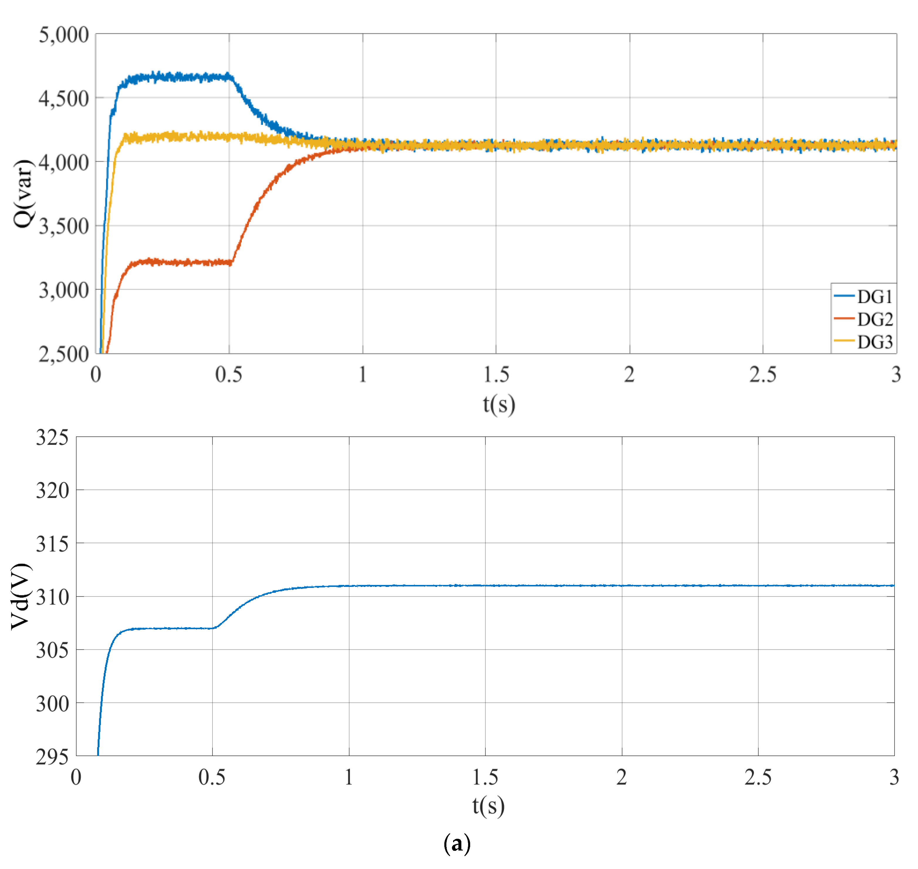
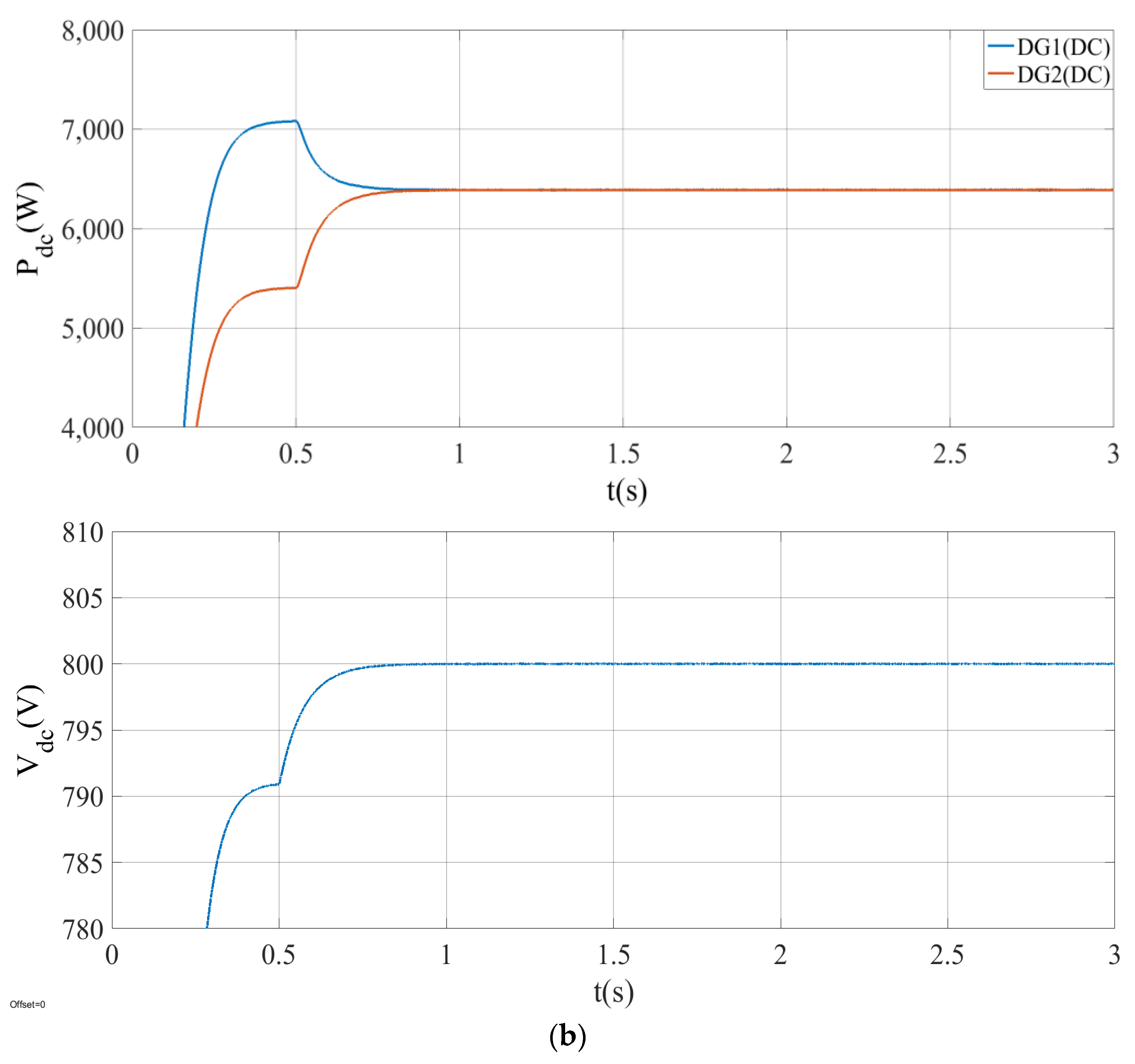
This part verifies the cooperative control strategies within the respective AC and DC subnets. The active and reactive load on the AC side are 21 kW and 12 kvar respectively, and the DC load is set to 12.8 kW. Initially, only primary control plays a role and the secondary control is put into service at t = 0.5 s. The control effect is shown in Figure 7:
As can be seen from Figure 7, a distributed coordinated control strategy shows a good performance in both AC and DC systems. During t = 0 s–0.5 s, DGs with lower output impedance share more load and the output voltage is lower than the rated value. After t = 0.5 s, secondary control is put into service, and accordingly, power redistributes in the MG and the average voltage tends to increase. At about t = 1 s, the AC system reaches steady state, DGs share the reactive load evenly, conforming to the principle of proportional sharing since they have the same capacity. Synchronously, the average voltage converges to the rating, 311 V. Likewise, at about t = 0.8 s, the DC system reaches steady state, the two DGs share the load evenly with their output power converging to 6.4 kW, concurrently, the average voltage converges to 800 V. Eventually, both systems operate under their ideal conditions.
4.2. Cooperative Control within Subnets
According to the national standard, the maximum and minimum fluctuation of AC frequency permitted are set to , while the maximum and minimum fluctuation of DC voltage permitted are set to .
Case 1: In general, the distribution of load in AC and DC systems is stochastic and usually disproportionate to the system capacity. Accordingly, in this case, the load on the AC side is set relatively heavier than that on the DC side to verify the capability of load sharing within and between subnets under the effect of the designed scheme. The active and reactive load on the AC side are 24 kW and 15.6 kvar, respectively, while the active load on the DC side is 14 kW. At t = 1 s, cooperative controls within AC and DC microgrids come into service simultaneously. At t = 2 s, cooperative control between AC and DC subnets is put into service. Figure 8 displays the frequency, active and reactive power sharing of the AC side, as well as the voltage and active power sharing of the DC side. To observe the cooperative operation between AC and DC subnets more intuitively, the values of on both sides, which represent the proportional sharing of power, are shown in Figure 8c.
In accordance with Table 1, the aggregate capacity of AC and DC systems is 60 kW and 160 kW respectively, with a ratio of 3:8 between them. Before t = 2 s, AC/DC cooperative control has not come into service, the output active power of each DG on the AC side is 8 kW, while that on DC side is 7 kW, and the AC side takes a much heavier active load considering its capacity. Accordingly, the AC frequency falls to 49.925 Hz, while the DC voltage is on the high side, after t = 2 s. The AC/DC cooperative control is put into service, and the active power in AC/DC hybrid microgrids redistributes in proportion to their capacity. The bidirectional converter works in inverter mode, the DC side transmits more power to the AC side through a bidirectional converter to share more load, the output active power of each DG on the DC side increases to 13.8 kW, and that on the AC side decreases to 3.5 kW. Correspondingly, the AC frequency increases to 49.965 Hz. Deduced from the above analysis, the actual output power on both sides is 10.5 kW and 27.6 kW, according to the desired ratio. The last figure intuitively indicates that the control strategy in this paper implements optimal power sharing effectively and the stability of the AC/DC hybrid system is enhanced.
By contrast, provided that the classical control scheme for the bidirectional converter based on the deviation of normalized voltage and frequency is adopted in the above case, owing to the greater value of normalized voltage, the controller will issue an instruction to increase the load assumed by the DC system continuously until it assumes the full load, which will be detrimental to the utmost utilization of system capacity.
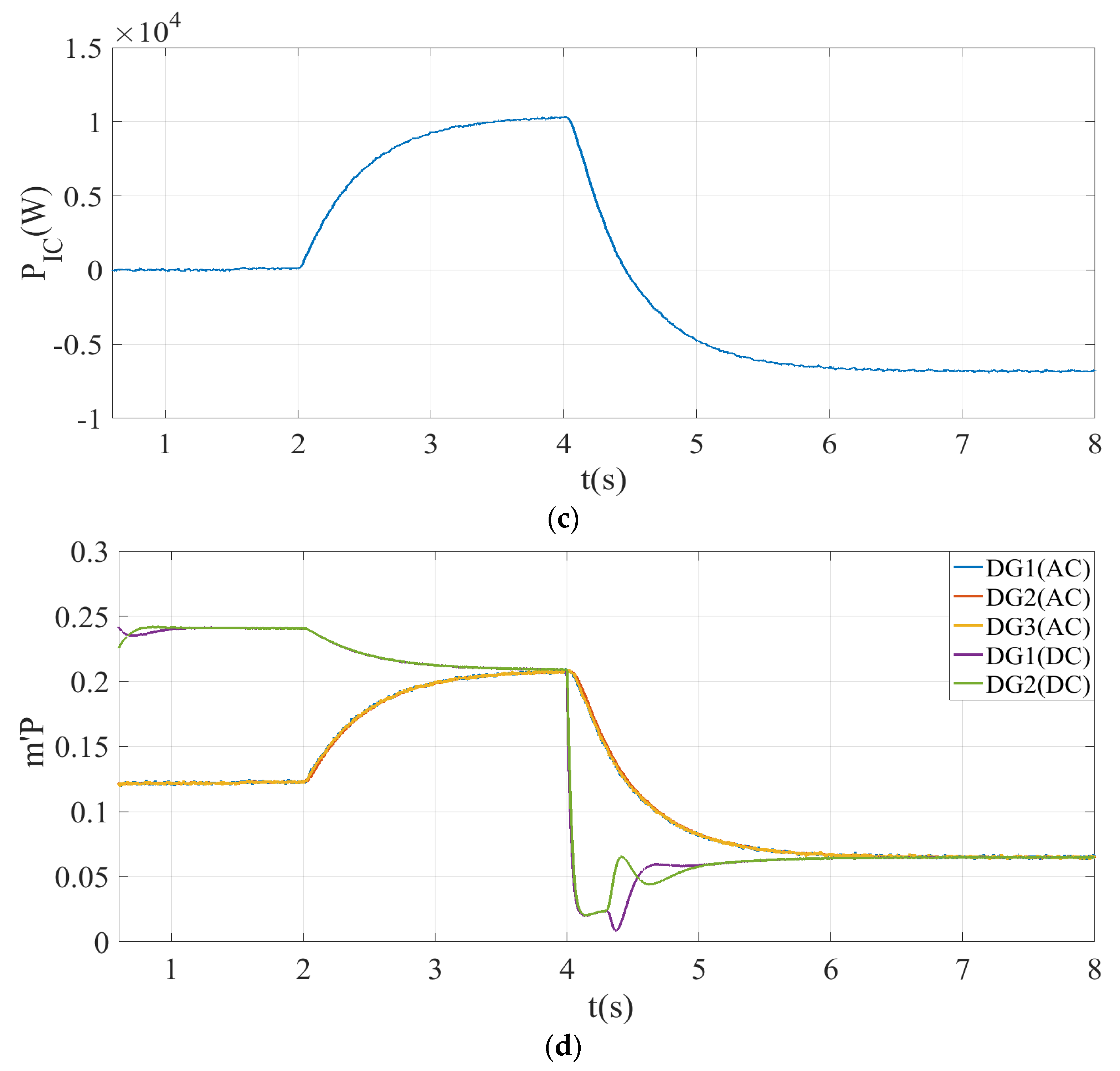
Case 2: In practice, under the circumstance of load shedding on one side due to a planned or unexpected incident, mode switch of the bidirectional converter occasionally occurs. To simulate this situation, the following scenario is designed. Initially, the active and reactive load on the AC side are 14.5 kW and 4.5 kvar, respectively, and the load on the DC side is 76 kW. At t = 2 s, AC/DC cooperative control comes into service, and at t = 4 s, 68 kW active load is cut off from the DC side. Figure 9 shows the changes of power on both sides, as well as the transmission power of the bidirectional converter, and compares the values of all DGs in the MG to show global proportional sharing of active power more intuitively.
As is displayed in Figure 9, before t = 2 s, average active power output of DGs on the AC side is 5.25 kW, while that on the DC side is 38 kW, which indicates a disproportionate allocation. At t = 2 s, active power redistributes, active output of DGs on the AC side increases to 8.25 kW and that on the DC side decreases to 33.5 kW. Hence, the output power of AC and DC systems can be calculated as 24.75 kW and 67 kW, respectively, implying an approximate ratio of 3:8 between them. Concurrently, active power tends to distribute proportionally within MGs. At this point, the bidirectional converter works in rectifier state. At t = 4 s, the DC side cuts off partial loads suddenly, accordingly, the output power of each DG decreases to 4 kW. At this time, DGs on the AC side assume a relatively heavier load. As a response, the bidirectional converter switches to inverter state. Under the cooperative control, the output power of the AC system decreases to 7.8 kW, while that of the DC system increases to 20.8 kW, holding a ratio of 3:8. Thus, the proportional sharing is resumed.
In the above simulation, diverse droop gain exerts an influence on system stability [21] and the selection of secondary controller parameters brings about changes to the system response as well, with a smaller integral coefficient corresponding to a longer settling time. Furthermore, the integral coefficient is strongly associated with the system robustness [22]. Reasonable parameter design can commendably ameliorate the system dynamic performance. Furthermore, it deserves extra attention that in practical application, measurement errors are unavoidable [23]; additionally, time− varying latency exists [23,24] during the information transfer process of both sides. These unfavorable factors should be given adequate consideration as they may impose an adverse influence on the control precision and system dynamic performance.
5. Conclusions
This paper extends the conventional proportional power sharing conditions in separate microgrids to an AC/DC hybrid system based on normalizing and synthesizing, and then combines the cooperative control between the AC and DC systems with secondary control within subnets. It thus proposes a global cooperative control strategy for AC/DC hybrid autonomous microgrids. Simulation results on MATLAB have revealed the satisfactory control effect of this scheme.
This paper provides a befitting optimization for hybrid AC/DC systems, especially those with severely unbalanced AC and DC load. The coordination within and between subnets are implemented simultaneously and excellently; moreover, voltage restores to the ideal value commendably, which is beneficial to take full advantage of the capacity of each DG in hybrid microgrids and gives better play to the efficiency and stability of MGs.
Author Contributions
Theoretical guidance, W.S.; Implementation and simulation, Y.H.; Analysis, M.W. and Y.J.; Composing an original manuscript, Y.H.; Polishing up the article, W.S.; Project management, W.S, M.W. and Y.J. All authors have read and agreed to the published version of the manuscript.
Funding
This research was supported by National Science Foundation of China, Grant 51477029.
Conflicts of Interest
The authors declare no conflict of interest.
References
- Eghtedarpour, N.; Farjah, E. Power Control and Management in a Hybrid AC/DC Microgrid. IEEE T Smart Grid 2014, 5, 1494–1505. [Google Scholar] [CrossRef]
- Nejabatkhah, F.; Li, Y.W. Overview of Power Management Strategies of Hybrid AC/DC Microgrid. IEEE Trans. Power Electron. 2015, 30, 7072–7089. [Google Scholar] [CrossRef]
- Karimi, M.; Azizipanah-Abarghooee, R.; Uppal, H. Smart integrated adaptive centralized controller for islanded microgrids under minimized load shedding. In Proceedings of the 2017 5th International Istanbul Smart Grid and Cities Congress and Fair, Istanbul, Turkey, 19–21 April 2017. [Google Scholar]
- Abdelaziz, M.M.A.; Shaaban, M.F.; Farag, H.E. A Multistage Centralized Control Scheme for Islanded Microgrids with PEVs. IEEE Trans. Sustain. Energy 2014, 5, 927–937. [Google Scholar] [CrossRef]
- Lou, G.N.; Gu, W.; Xu, Y.L. Distributed MPC-Based Secondary Voltage Control Scheme for Autonomous Droop-Controlled Microgrids. IEEE Trans. Sustain. Energy 2017, 8, 792–804. [Google Scholar] [CrossRef]
- Shayanfar, H.A.; Malek, S. Photovoltaic microgrids control by the cooperative control of multi-agent systems. In Proceedings of the 2015 30th International Power System Conference, Tehran, Iran, 23–25 November 2015. [Google Scholar]
- Luo, S.N.; Hu, C.B.; Zhang, Y.C. Multi-agent systems using model predictive control for coordinative optimization control of microgrid. In Proceedings of the 2017 20th International Conference on Electrical Machines and Systems, Sydney, NSW, Australia, 11–14 August 2017. [Google Scholar]
- Dehkordi, N.M.; Sadati, N. Fully Distributed Cooperative Secondary Frequency and Voltage Control of Islanded Microgrids. IEEE Trans. Energy Convers. 2017, 32, 675–685. [Google Scholar] [CrossRef]
- Dou, C.; Yue, D.; Zhang, Z.; Ma, K. MAS-Based Distributed Cooperative Control for DC Microgrid Through Switching Topology Communication Network With Time-Varying Delays. IEEE Syst. J. 2019, 13, 615–623. [Google Scholar] [CrossRef]
- Guo, F.H.; Xu, Q.W.; Wen, C.Y.; Wang, L.; Wang, P. Distributed Secondary Control for Power Allocation and Voltage Restoration in Islanded DC Microgrids. IEEE Trans. Sustain. Energy 2018, 9, 1857–1869. [Google Scholar] [CrossRef]
- Park, S.H.; Choi, J.Y.; Won, D.J. Cooperative control between the distributed energy resources in AC/DC hybrid microgrid. In Proceedings of the ISGT 2014, Washington, DC, USA, 19–22 February 2014. [Google Scholar]
- Ji, Y.; Wu, M.; Liu, H.T. Bidirectional Droop Control of Interlinking Converter in AC/DC Hybrid Micro-grid. In Proceedings of the 2016 3rd International Conference on Information Science and Control Engineering, Beijing, China, 8–10 July 2016. [Google Scholar]
- Hu, W.Y.; Chen, H.K.; Yang, X.N. Control strategy of the bi-directional converter for hybrid AC/DC microgrid. In Proceedings of the 2015 IEEE PES Asia-Pacific Power and Energy Engineering Conference, Brisbane, QLD, Australia, 15–18 November 2015. [Google Scholar]
- Li, X.L.; Guo, L.; Li, Y.W. A Unified Control for the DC–AC Interlinking Converters in Hybrid AC/DC Microgrids. IEEE T Smart Grid 2018, 9, 6540–6553. [Google Scholar] [CrossRef]
- Wang, J.; Jin, C.; Wang, P. A Uniform Control Strategy for the Interlinking Converter in Hierarchical Controlled Hybrid AC/DC Microgrids. IEEE Trans. Ind. Electron. 2018, 65, 6188–6197. [Google Scholar] [CrossRef]
- Zhang, B.F.; Cao, G.D.; Ren, C.G. Autonomous Control Strategy of Bidirectional AC/DC Converter in Low Voltage Hybrid Microgrid. In Proceedings of the 2017 12th IEEE Conference on Industrial Electronics and Applications, Siem Reap, Cambodia, 18–20 June 2017. [Google Scholar]
- Loh, P.C.; Li, D.; Chai, Y.K.; Blaabjerg, F. Autonomous Control of Interlinking Converter with Energy Storage in Hybrid AC–DC Microgrid. IEEE Trans. Ind. Appl. 2013, 49, 1374–1382. [Google Scholar] [CrossRef]
- Zhong, Q.C. Robust droop controller for accurate proportional load sharing among inverters operated in parallel. IEEE Trans. Ind. Electron. 2013, 60, 1281–1290. [Google Scholar] [CrossRef]
- Lou, G.N.; Gu, W.; Wang, J.H. Optimal Design for Distributed Secondary Voltage Control in Islanded Microgrids: Communication Topology and Controller. IEEE Trans. Power Syst. 2019, 34, 968–981. [Google Scholar] [CrossRef]
- Zhou, J.G.; Zhang, H.G.; Sun, Q.Y. Event-Based Distributed Active Power Sharing Control for Interconnected AC and DC Microgrids. IEEE T Smart Grid 2018, 9, 6815–6828. [Google Scholar] [CrossRef]
- Liu, Z.W.; Miao, S.H.; Kang, Y.L. A bidirectional droop control strategy for the hybrid microgrid with AC/DC distributed generation integration. In Proceedings of the 2018 13th IEEE Conference on Industrial Electronics and Applications, Wuhan, China, 31 May–2 June 2018. [Google Scholar]
- Lou, G.N.; Gu, W.; Xu, Y.L. Stability Robustness for Secondary Voltage Control in Autonomous Microgrids With Consideration of Communication Delays. IEEE Trans. Power Syst. 2018, 33, 4164–4178. [Google Scholar] [CrossRef]
- Xiao, F.; Shi, Y.; Ren, W. Robustness Analysis of Asynchronous Sampled-Data Multiagent Networks With Time-Varying Delays. IEEE Trans. Autom. Control. 2018, 63, 2145–2152. [Google Scholar] [CrossRef] [Green Version]
- Zhan, J.; Li, X. Asynchronous Consensus of Multiple Double-Integrator Agents With Arbitrary Sampling Intervals and Communication Delays. IEEE Trans. Circuits Syst. I Regul. Pap. 2015, 62, 2301–2311. [Google Scholar] [CrossRef]
Figure 1.
Typical topology of the AC/DC hybrid microgrid.

Figure 2.
Initial droop control curves. (a) Droop control curves in the AC subnet; (b) droop control curves in the DC subnet.
Figure 2.
Initial droop control curves. (a) Droop control curves in the AC subnet; (b) droop control curves in the DC subnet.
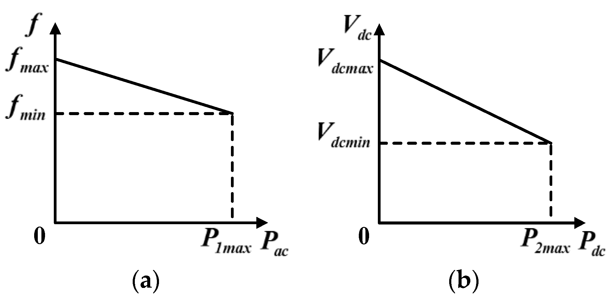
Figure 3.
Droop control curves of the whole MG. (a) AC microgrid; (b) DC microgrid.

Figure 4.
Flow chart of the AC/DC cooperative control.
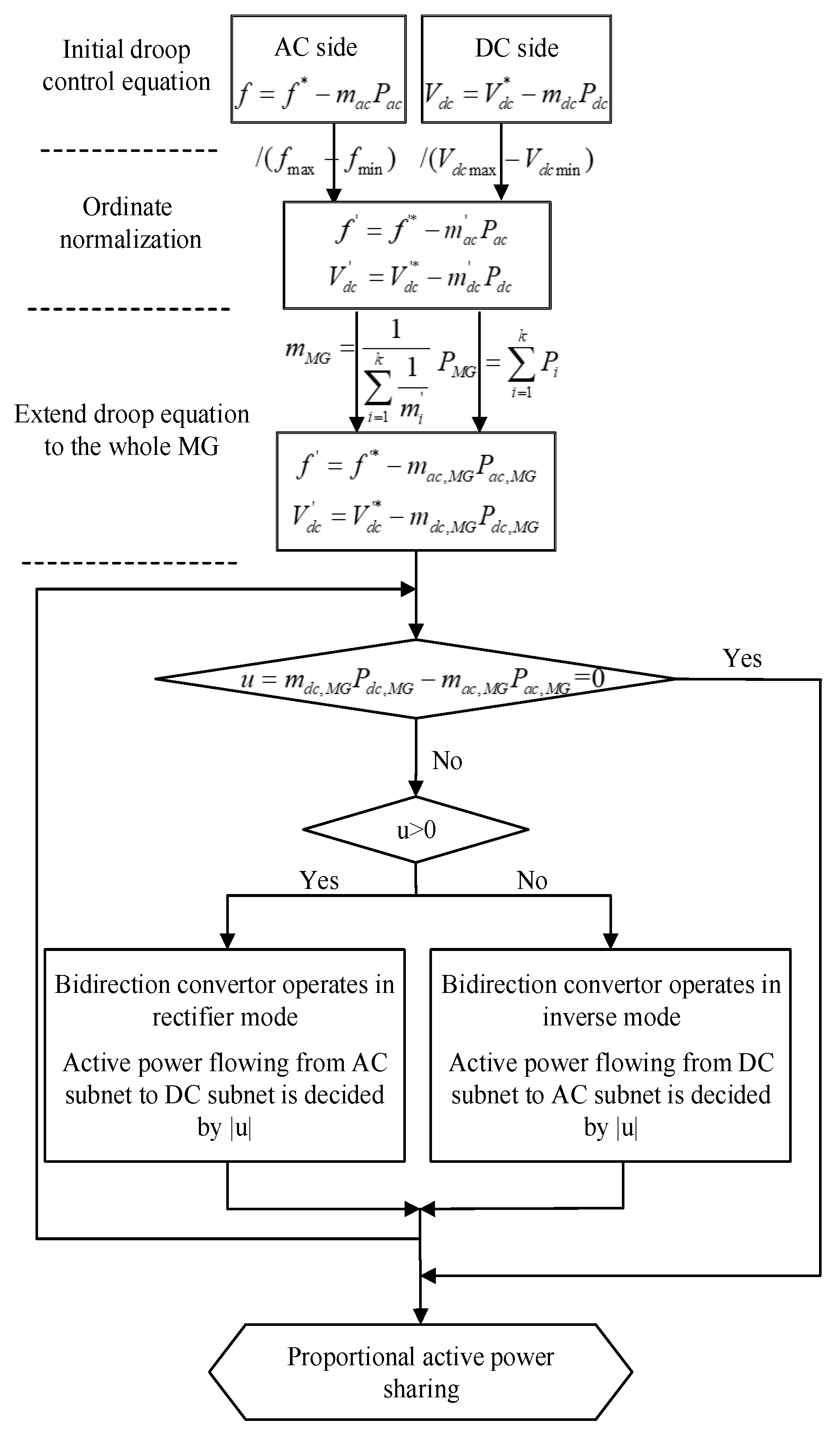
Figure 5.
General control schematic diagram of an AC/DC hybrid microgrid.
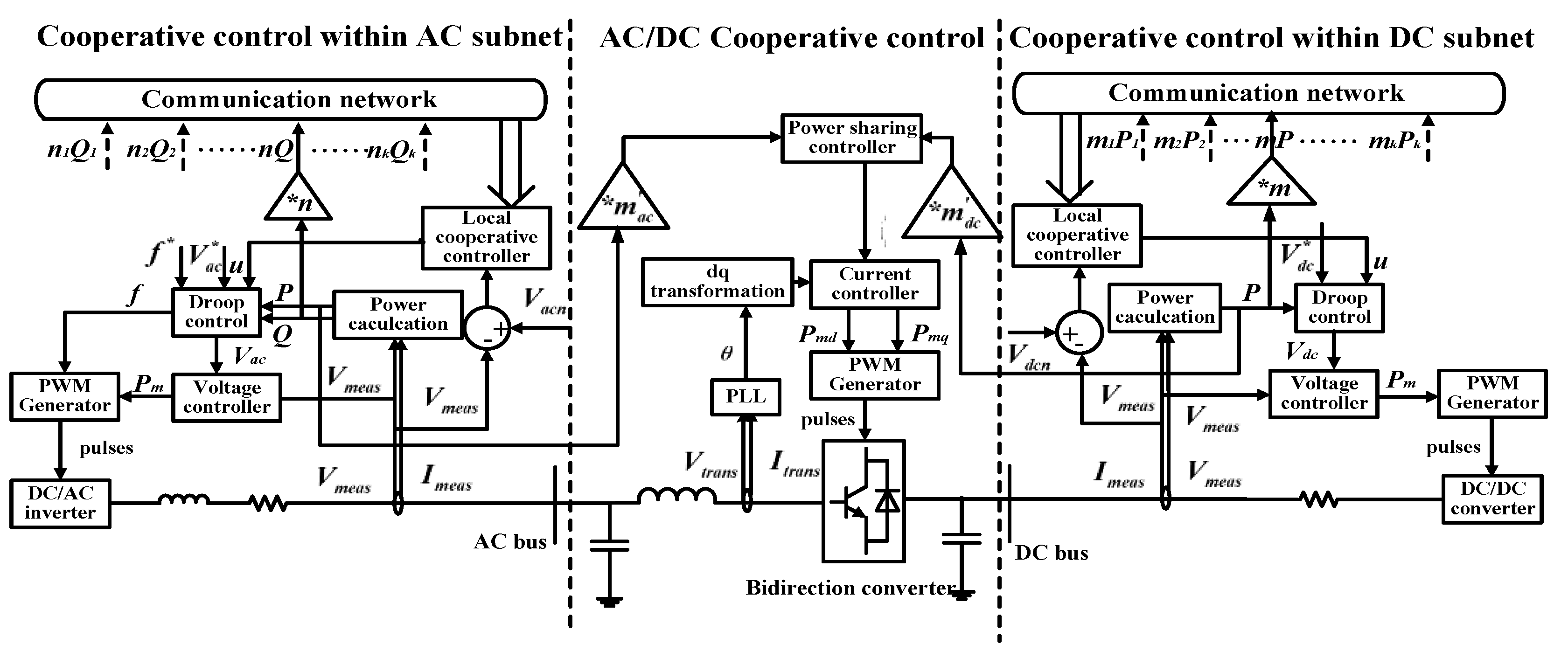
Figure 6.
Simplified structure of the test AC/DC hybrid system.

Figure 7.
Simulation results under cooperative control within subnets. (a) In the AC subnet; (b) in the DC subnet.
Figure 7.
Simulation results under cooperative control within subnets. (a) In the AC subnet; (b) in the DC subnet.


Figure 8.
Simulation results of case 1. (a) In the AC subnet; (b) in the DC subnet; (c) of all DGs.


Figure 9.
Simulation results of case 2. (a) In the AC subnet; (b) in the DC subnet; (c) of the bidirectional converter; (d) of all DGs.
Figure 9.
Simulation results of case 2. (a) In the AC subnet; (b) in the DC subnet; (c) of the bidirectional converter; (d) of all DGs.


Table 1.
Main Parameters of the Test System.
| AC Side | DC Side | |||
|---|---|---|---|---|
| Rated Value | Voltage | 380 V/50 Hz | Voltage | 800 V |
| Power of DG1–3 | 20 kW | Power of DG1–2 | 80 kW | |
| 38 kvar | ||||
| Droop Coefficient | 1 × 10⁻⁵ | 1 × 10⁻³ | ||
| 1 × 10⁻³ | ||||
| Output Impendence | Z1 | 0.05 + 0.126 j | R1 | 0.15 |
| Z2 | 0.1 + 0.283 j | |||
| R2 | 0.2 | |||
| Z3 | 0.07 + 0.157 j | |||
© 2020 by the authors. Licensee MDPI, Basel, Switzerland. This article is an open access article distributed under the terms and conditions of the Creative Commons Attribution (CC BY) license (http://creativecommons.org/licenses/by/4.0/).
Share and Cite
MDPI and ACS Style
Sheng, W.; Hong, Y.; Wu, M.; Ji, Y. A Cooperative Control Scheme for AC/DC Hybrid Autonomous Microgrids. Processes 2020, 8, 311. https://doi.org/10.3390/pr8030311
AMA Style
Sheng W, Hong Y, Wu M, Ji Y. A Cooperative Control Scheme for AC/DC Hybrid Autonomous Microgrids. Processes. 2020; 8(3):311. https://doi.org/10.3390/pr8030311
Chicago/Turabian StyleSheng, Wanxing, Yinqiu Hong, Ming Wu, and Yu Ji. 2020. "A Cooperative Control Scheme for AC/DC Hybrid Autonomous Microgrids" Processes 8, no. 3: 311. https://doi.org/10.3390/pr8030311
Note that from the first issue of 2016, this journal uses article numbers instead of page numbers. See further details here.