
Towards High Efficiency CO2 Utilization by Glow Discharge Plasma

Electrical Energy Storage Systems, Institute for Photovoltaics, University of Stuttgart, Pfaffenwaldring 47, 70569 Stuttgart, Germany
*
Author to whom correspondence should be addressed.
Processes 2021, 9(11), 2063; https://doi.org/10.3390/pr9112063
Submission received: 11 October 2021
/
Revised: 11 November 2021
/
Accepted: 15 November 2021
/
Published: 18 November 2021
(This article belongs to the Topic Energy Storage and Conversion Systems)
Abstract
:Plasma technology reaches rapidly increasing efficiency in catalytic applications. One such application is the splitting reaction of CO2 to oxygen and carbon monoxide. This reaction could be a cornerstone of power-to-X processes that utilize electricity to produce value-added compounds such as chemicals and fuels. However, it poses problems in practice due to its highly endothermal nature and challenging selectivity. In this communication a glow discharge plasma reactor is presented that achieves high energy efficiency in the CO2 splitting reaction. To achieve this, a magnetic field is used to increase the discharge volume. Combined with laminar gas flow, this leads to even energy distribution in the working gas. Thus, the reactor achieves very high energy efficiency of up to 45% while also reaching high CO2 conversion efficiency. These results are briefly explained and then compared to other plasma technologies. Lastly, cutting edge energy efficiencies of competing technologies such as CO2 electrolysis are discussed in comparison.
1. Introduction
Many fields offer solutions for CO2 utilization. Among them are thermochemical processes, electrolysis [1] and plasma catalysis; the latter has the smallest technology readiness level (TRL) but also offers a large potential for future improvements [2,3,4]. Attention is focused mostly on four types of plasma reactors: dielectric barrier discharges (DBDs) [5], gliding arc (GA) [6,7], atmospheric pressure glow discharges (APGD) [8,9] and microwave (MW) plasmas [10,11]. Increasing their energy efficiency and conversion at ambient pressure is the main point of concern. We recently presented reactors using a direct current APGD, which delivered promising results [12]. To further improve the previous design, it was scaled and now uses a laminar gas flow instead of a turbulent one. To be used industrially, a plasma reactor should operate at ambient pressure. However, this makes it hard to maintain a stable discharge. Two major difficulties are the negative differential resistance [13] and glow-to-arc transition [14]. A discharge thus tends to form a narrow, low-resistance arc that can damage the plasma source and is not useful in catalysis. To suppress these effects, current control strategies or vortex gas flow [14] are often used in recent studies to disperse the plasma [8]. The reactor setup presented here uses a magnetic field instead to force the plasma into a large disc-like volume. This approach is viable for various discharge forms, such as gliding arc plasma reactors [15,16]. A laminar gas flow can be then used to introduce energy into the working gas as homogeneously as possible. This communication aims to give an update on the ongoing design process for an improved plasma reactor for the CO2 splitting reaction.
2. Materials and Methods
The reactor vessel was a glass tube with an inner diameter of 38 mm. Direct current formed a discharge between two copper electrodes. One was an axial rod, the other a ring. CO2 was introduced into the reactor through an injection plate with 22 axial nozzles in concentric nozzles, arranged in concentric circles. The injector was placed 120 mm above the plane of the electrodes. An axial magnetic field was provided by permanent magnets below the electrode assembly, and the field strength was 30 mT on the central axis. A packed bed made from zirconia balls was placed 2 mm below the discharge plane inside the ring electrode. It serves to suppress thermal currents in the gas and could also help with quenching the hot exhaust gas. Zirconia was chosen because it is chemically inert, non-conductive and can be used to carry catalysts in future experiments. The reactor assembly is shown in Figure 1. The input gas flow consisted of pure CO2. It was measured by an analogue rotameter and adjusted using a needle valve. The assembly was calibrated using a displacement cylinder. The exhaust gas was characterized using non-dispersive infrared sensors (SmartGas Flow Evo; Heilbronn; Germany); measurements at a flow of 1.4 SLM were confirmed by a gas chromatographer (Trace 1310 Thermo Scientific; Waltham, MA, USA). The sensors were placed 1 m downstream from the reactor in the exhaust gas pipe. Power was provided to the electrodes by a custom current-limiting driver circuit. It delivers direct current for ignition (up to 25 kV) and is sustaining of the discharge (<2 kV). Mean burn voltage of the discharge and mean current were measured. Mean values are deemed sufficient here, because a large choke inductor of 1.5 H was placed on the output of the driver circuit, leading to low current ripple. Voltage ripple was typically around 15%. The discharge power Pd was calculated from the power supplied to the driver circuit by a lab power supply and the known driver efficiency. To confirm these values, they can also be calculated as the product of burn voltage and current. CO2 conversion X is calculated using Equation (1), while energy efficiency η is calculated by Equation (2). They use the concentrations of CO and CO2 in the exhaust gas. ΔHr = 12.6 J SCC−1 (standard cubic centimeter) is the reaction enthalpy of the CO2 splitting reaction. Measurements of the gas concentrations were taken after a steady state in exhaust gas concentrations occurred.
3. Results
The achieved CO2 conversion X and energy efficiency η for different discharge power Pd and gas flow rates Vin is shown in Figure 2. The highest conversion X was achieved at a discharge power of Pd = 165 W. The best energy efficiency that was achieved is 45% at the highest gas flow rate of 1.25 SLM. The effectiveness of the magnetic field could be determined visibly: the discharge rotates quickly, so it gives the appearance of a disk to the naked eye. This leads to very homogeneous energy input into the gas. Quantizing the influence of the magnetic field will be the subject of future experiments.
4. Discussion
4.1. Performance of the Reactor
Conversion depends strongly on discharge power Pd. One reason is that higher power equals higher specific energy input. Additionally, the properties of the plasma, such as temperature, electron density and reduced electric field, can also be expected to change with the discharge power. In this reactor the rotation of the discharge filament accelerates at higher discharge powers. This can also be expected to have a positive influence on the conversion, since the gas will be swept more efficiently by the plasma. However, the conversion does not increase with power indefinitely. At the highest discharge power of Pd = 192W, conversion reduces. One reason could be the heating of the packed bed. This heating reduces the quenching rate, which increases the rate of the recombination reaction, thus again forming CO2 [11]. Energy efficiency seems to mainly depend on gas flow rate but also decreases at high discharge powers.
4.2. Comparison to Other Technologies
The results achieved compare well to other plasma-based systems, as shown in Figure 3a. They were selected based on performance from a broader range of systems previously reviewed [17], considering more recent work. Gliding arcs provide high efficiency at ambient pressure; a vortex is often used to increase the discharge volume [6,7]. Gliding arcs also obtain good results without vortex flow [18]. Glow discharges can also benefit from vortex gas flow [8]. Increasing their stability is possible by operation in non-self-sustaining mode [9]. DBDs that moderate efficiency and conversion could be boosted by using a burst mode, where high power density is applied intermittently [5]. Microwave plasmas reach the most promising results to date [10]. However, these were obtained at very low pressures, and at ambient pressures even after utilizing precise quenching, efficiency is lower, yet still impressive [11]. The highest efficiencies reported in literature were achieved at a very low pressure by radio frequency excitation at a pressure of just 40 Pa [19]. A common theme in the results seems to be that a homogeneous energy input into the gas results in good performance. Vortex gas flow as used in [6,7,8] can distribute energy well but is ultimately a chaotic process that will not lead to even energy distribution. In contrast, the combination of laminar flow and a disk-like discharge can distribute energy very evenly.
In the following, a quantitative assessment of different CO2 conversion technologies regarding energy efficiency η is given. The comparison has no claim for completeness and focuses only on the actual conversion step of CO2 to CO; influences on a systemic level or scaling effects are not included here. This approach allows a comparison of vastly different technologies but is not intended as a ranking given that each technology has its own ideal configuration in which the full potential can be realized. Figure 3b shows calculated energy efficiencies drawn from recent publications (see Appendix A for the calculation). The technologies included are low temperature, gas-phase CO2 electrolysis [20], high temperature CO2 electrolysis in a solid oxide electrolysis cell [21], a thermochemical approach (Reverse Water Gas Shift, RWGS) [22] and the plasma approach reported in this work. The energy efficiencies given in Figure 3b show that each technology has the potential to enable a reasonable application. This is reasoned on the basis that systemic effects of the individual application have the potential to outweigh the differences inherent to the energy efficiency of the CO2 conversion.
5. Conclusions
The presented glow discharge plasma reactor achieves a competitive CO2 conversion of 27% and energy efficiency of 42%. This is a respectable performance since the process was running at ambient pressure. We attribute this good performance to the efficient sweeping of the gas by the discharge due to the magnetic field. In general, the energy efficiency of plasma-based systems is gaining ground compared to competing technologies such as electrolysis and thermochemical approaches. Focus thus shifts to scalability, lifespan and, most importantly, integration. After all, none of the presented technologies manage to produce pure product gases; their separation is a major task for which few technologies are available. The integration of electrochemical oxygen pumps or separation membranes into plasma reactor systems will be a future focus. Our results illustrate that plasma technology can play an important role in CO2 utilization, which is a cornerstone of a fossil-free economy.
Author Contributions
Conceptualization, S.R., J.S. and P.R.; methodology, S.R; investigation, S.R., M.L. and J.S.; resources, K.P.B.; writing—original draft preparation, S.R.; writing—review and editing, P.R. and M.L.; visualization, S.R.; supervision, K.P.B.; project administration, M.L.; funding acquisition, K.P.B. All authors have read and agreed to the published version of the manuscript.
Funding
This work was funded by the Federal Ministry for Economic Affairs and Energy (Germany) in the scope of their initiative “Energy transition in the transport sector” and the associated “PlasmaFuel” project (Funding code: 03EIV161A).
Informed Consent Statement
Not applicable.
Data Availability Statement
The data is not filed into a public repository but will be kindly provided upon request.
Conflicts of Interest
The authors declare no conflict of interest.
Appendix A
The energy efficiency of electrolysis is calculated considering electrical Eel and thermal energy Eth input following Equation (A1). Thermal energy is calculated by using the heat capacity cp and temperature difference from ambient . Electrical energy is calculated using the Faradaic efficiency , cell voltage Ucell at a current density of 200 mA cm−2, electron number z and the Faraday constant F.
For the thermochemical approach, energy input is the sum of thermal energy used for gas heating and utilized hydrogen. Hydrogen was weighed as an energy expense of EH2 = 350 kJ mol−1.
References
- Saravanan, A.; Kumar, P.S.; Vo, D.-V.N.; Jeevanantham, S.; Bhuvaneswari, V.; Narayanan, V.A.; Yaashikaa, P.; Swetha, S.; Reshma, B. A comprehensive review on different approaches for CO2 utilization and conversion pathways. Chem. Eng. Sci. 2021, 236, 116515. [Google Scholar] [CrossRef]
- Bogaerts, A.; Centi, G. Plasma technology for CO2 conversion: A personal perspective on prospects and gaps. Front. Energy Res. 2020, 8, 111. [Google Scholar] [CrossRef]
- Bogaerts, A.; Tu, X.; Whitehead, J.C.; Centi, G.; Lefferts, L.; Guaitella, O.; Azzolina-Jurry, F.; Kim, H.-H.; Murphy, A.B.; Schneider, W.F. The 2020 plasma catalysis roadmap. J. Phys. D Appl. Phys. 2020, 53.44, 443001. [Google Scholar] [CrossRef]
- Grim, R.G.; Huang, Z.; Guarnieri, M.T.; Ferrell, J.R.; Tao, L.; Schaidle, J.A. Transforming the carbon economy: Challenges and opportunities in the convergence of low-cost electricity and reductive CO2 utilization. Energy Environ. Sci. 2019, 13, 472–494. [Google Scholar] [CrossRef]
- Ozkan, A.; Dufour, T.; Silva, T.; Britun, N.; Snyders, R.; Reniers, F.; Bogaerts, A. DBD in burst mode: Solution for more efficient CO2 conversion? Plasma Sources Sci. Technol. 2016, 25, 055005. [Google Scholar] [CrossRef] [Green Version]
- Trenchev, G.; Bogaerts, A. Dual-vortex plasmatron: A novel plasma source for CO2 conversion. J. CO2 Util. 2020, 39, 101152. [Google Scholar] [CrossRef]
- Ramakers, M.; Medrano, J.A.; Trenchev, G.; Gallucci, F.; Bogaerts, A. Revealing the arc dynamics in a gliding arc plasmatron: A better insight to improve CO2 conversion. Plasma Sources Sci. Technol. 2017, 26, 125002. [Google Scholar] [CrossRef]
- Bharathi, R.; Sarathi, R.; Vinu, R. Development of a Swirl-Induced Rotating Glow Discharge Reactor for CO2 Conversion: Fluid Dynamics and Discharge Dynamics Studies. Energy Technol. 2020, 8.12, 2000535. [Google Scholar]
- Andreev, S.; Zakharov, V.; Ochkin, V.; Savinov, S. Plasma-chemical CO2 decomposition in a non-self-sustained discharge with a controlled electronic component of plasma. Spectrochim. Acta Part A Mol. Biomol. Spectrosc. 2004, 60, 3361–3369. [Google Scholar] [CrossRef]
- Bongers, W.; Bouwmeester, H.J.; Wolf, B.; Peeters, F.; Welzel, S.; Bekerom, D.V.D.; Harder, N.D.; Goede, A.; Graswinckel, M.; Groen, P.W.; et al. Plasma-driven dissociation of CO2 for fuel synthesis. Plasma Process. Polym. 2016, 14, e1600126. [Google Scholar] [CrossRef] [Green Version]
- Kim, H.; Song, S.; Tom, C.P.; Xie, F. Carbon dioxide conversion in an atmospheric pressure microwave plasma reactor: Improving efficiencies by enhancing afterglow quenching. J. CO2 Util. 2019, 37, 240–247. [Google Scholar] [CrossRef]
- Renninger, S.; Lambarth, M.; Birke, K.P. High efficiency CO2-splitting in atmospheric pressure glow discharge. J. CO2 Util. 2020, 42, 101322. [Google Scholar] [CrossRef]
- Saifutdinov, A.I.; Timerkaev, B.A. Features of Transient Processes in DC Microdischarges in Molecular Gases: From a Glow Discharge to an Arc Discharge with a Unfree or Free Cathode Regime. JETP Lett. 2020, 112, 405–412. [Google Scholar] [CrossRef]
- Rabinovich, A.; Nirenberg, G.; Kocagoz, S.; Surace, M.; Sales, C.; Fridman, A. Scaling Up of Non-Thermal Gliding Arc Plasma Systems for Industrial Applications. Plasma Chem. Plasma Process. 2021, 1–16. [Google Scholar] [CrossRef]
- Li, L.; Zhang, H.; Li, X.; Huang, J.; Kong, X.; Xu, R.; Tu, X. Magnetically enhanced gliding arc discharge for CO2 activation. J. CO2 Util. 2019, 35, 28–37. [Google Scholar] [CrossRef]
- Zhang, H.; Li, L.; Li, X.; Wang, W.; Yan, J.; Tu, X. Warm plasma activation of CO2 in a rotating gliding arc discharge reactor. J. CO2 Util. 2018, 27, 472–479. [Google Scholar] [CrossRef]
- Snoeckx, R.; Bogaerts, A. Plasma technology—A novel solution for CO2 conversion? Chem. Soc. Rev. 2017, 46.19, 5805–5863. [Google Scholar] [CrossRef] [PubMed] [Green Version]
- Kim, S.C.; Lim, M.S.; Chun, Y.N. Reduction Characteristics of Carbon Dioxide Using a Plasmatron. Plasma Chem. Plasma Process. 2013, 34, 125–143. [Google Scholar] [CrossRef]
- Spencer, L.F.; Gallimore, A.D. Efficiency of CO2 Dissociation in a Radio-Frequency Discharge. Plasma Chem. Plasma Process. 2010, 31, 79–89. [Google Scholar] [CrossRef]
- Liu, Z.; Yang, H.; Kutz, R.; Masel, R.I. CO2 Electrolysis to CO and O2 at High Selectivity, Stability and Efficiency Using Sustainion Membranes. J. Electrochem. Soc. 2018, 165, J3371–J3377. [Google Scholar] [CrossRef]
- Kaur, G.; Kulkarni, A.P.; Giddey, S. CO2 reduction in a solid oxide electrolysis cell with a ceramic composite cathode: Effect of load and thermal cycling. Int. J. Hydrogen Energy 2018, 43, 21769–21776. [Google Scholar] [CrossRef]
- Zonetti, C.P.; Letichevsky, S.; Gaspar, A.B.; Sousa-Aguiar, E.F.; Appel, L.G. The NixCe0.75Zr0.25−xO2 solid solution and the RWGS. Appl. Catal. A Gen. 2014, 475, 48–54. [Google Scholar] [CrossRef]
Figure 1.
Overview over the plasma reactor assembly (a) and schematic view of the discharge (b).

Figure 2.
Performance of the reactor at different gas flow rates Vin and discharge power Pd. In (a), the conversion X is shown while (b) displays energy efficiency .
Figure 2.
Performance of the reactor at different gas flow rates Vin and discharge power Pd. In (a), the conversion X is shown while (b) displays energy efficiency .
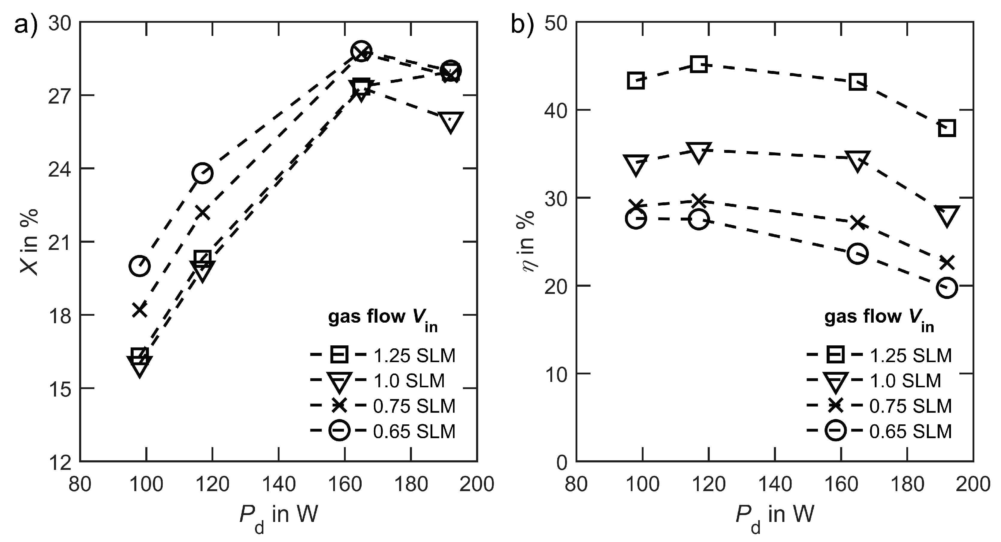
Figure 3.
A comparison of the achieved energy efficiency and conversion X for CO2 splitting by plasma is shown in (a). In (b) the results are compared to high temperature electrolysis (HT-el.), low temperature electrolysis (LT-el.) and reverse water gas shift (RWGS).
Figure 3.
A comparison of the achieved energy efficiency and conversion X for CO2 splitting by plasma is shown in (a). In (b) the results are compared to high temperature electrolysis (HT-el.), low temperature electrolysis (LT-el.) and reverse water gas shift (RWGS).

Publisher’s Note: MDPI stays neutral with regard to jurisdictional claims in published maps and institutional affiliations. |
© 2021 by the authors. Licensee MDPI, Basel, Switzerland. This article is an open access article distributed under the terms and conditions of the Creative Commons Attribution (CC BY) license (https://creativecommons.org/licenses/by/4.0/).
Share and Cite
MDPI and ACS Style
Renninger, S.; Rößner, P.; Stein, J.; Lambarth, M.; Birke, K.P. Towards High Efficiency CO2 Utilization by Glow Discharge Plasma. Processes 2021, 9, 2063. https://doi.org/10.3390/pr9112063
AMA Style
Renninger S, Rößner P, Stein J, Lambarth M, Birke KP. Towards High Efficiency CO2 Utilization by Glow Discharge Plasma. Processes. 2021; 9(11):2063. https://doi.org/10.3390/pr9112063
Chicago/Turabian StyleRenninger, Stephan, Paul Rößner, Jan Stein, Maike Lambarth, and Kai Peter Birke. 2021. "Towards High Efficiency CO2 Utilization by Glow Discharge Plasma" Processes 9, no. 11: 2063. https://doi.org/10.3390/pr9112063
Note that from the first issue of 2016, this journal uses article numbers instead of page numbers. See further details here.