Article

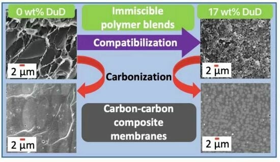
Carbon–Carbon Composite Membranes Derived from Small-Molecule-Compatibilized Immiscible PBI/6FDA-DAM-DABA Polymer Blends

by
Chamaal Karunaweera
,
Nimanka P. Panapitiya
,
Samitha Panangala
,
Edson V. Perez
,
Inga H. Musselman
,
Kenneth J. Balkus, Jr.
and
John P. Ferraris
*
Department of Chemistry and Biochemistry, The University of Texas at Dallas, 800 W. Campbell Rd, Richardson, TX 75080, USA
*
Author to whom correspondence should be addressed.
Separations 2024, 11(4), 108; https://doi.org/10.3390/separations11040108
Submission received: 28 February 2024 / Revised: 21 March 2024 / Accepted: 26 March 2024 / Published: 1 April 2024
(This article belongs to the Section Materials in Separation Science)

Abstract

:
The use of immiscible polymer blends in gas separations is limited due to uncontrollable phase separation. In contrast, compatibilized immiscible polymer blends can be used as precursors with controlled morphologies that allow for a unique pore architecture. Herein, an immiscible polymer blend (1:1) comprising polybenzimidazole (PBI) and the copolyimide 6FDA-DAM:DABA [3:2], derived from reacting 4,4-(hexafluoroisopropylidene)diphthalic anhydride (6FDA) with 2,4,6-trimethyl-1,3-phenylenediamine (DAM) and 3,5-diaminobenzoic acid (DABA), were combined with durene diamine as a compatibilizer. The compatibilizer helped reduce the 6FDD domain sizes from 5.6 µm down to 0.77 µm and induced a more even 6FDA distribution and the formation of continuous thin-selective PBI layers. The carbon–carbon composite membranes derived from the compatibilized immiscible polymer blends showed a 3-fold increase in both H2 permeability and H2/CO2 selectivity compared to the membranes derived from non-compatibilized polymer blends. The H2 permeability of the compatibilized immiscible polymer blends increased from 3.6 to 27 Barrer, and their H2/CO2 selectivity increased from 7.2 to 20. The graphitic domain size of the carbon–carbon composite membranes derived from the polymer blends also increased from 6.3 nm for the non-compatibilized blend to 10.0 nm for the compatibilized blend.

Graphical Abstract

1. Introduction

Membrane-based gas separations have become an active research topic over the past few decades [1,2,3,4,5,6]. Among the different types of membrane systems studied, carbon molecular sieve membranes (CMSMs) are attractive due to their stability under harsh industrial conditions (e.g., high temperature), their chemical resistance, and their unprecedented gas separation performance [7,8,9,10]. The separation properties of CMSMs are critically dependent on the membrane microstructure, which reflects, in part, that of the precursor polymer [7]. Previous studies showed that it is difficult to control the microstructure and associated properties of a CMSM by using a single polymer precursor [7,8]. Some degree of control of the microstructure of a CMSM may be achieved by blending polymers before the carbonization. As we have previously reported, polymer blends can control the polymer membrane microstructure [11,12] by adjusting the composition and incorporating compatibilizers. This approach has now been extended to the preparation of CMSMs with superior gas separation properties.
CMSMs possess enhanced separation properties due to their distinct pore sizes (2.5 Å to 7 Å) that are small enough to distinguish gas molecules based on their kinetic diameters (e.g., He = 2.6 Å, H2 = 2.89 Å, CO2 = 3.3 Å, O2 = 3.46 Å, N2 = 3.64 Å, CH4 = 3.8 Å, C3H8 = 4.3 Å, C3H6 = 4.5 Å). CMSMs separate gases primarily through adsorption and molecular sieving mechanisms that depend on the microstructure of the membrane, in which the micropores, 7 Å to 20 Å, allow for fast gas diffusion and the ultramicropores (<7 Å) provide selectivity [13,14,15,16]. Hence, control of the pore structure of CMSMs is essential to optimize their permeability and selectivity. The selection of the polymer precursor is the most common factor considered when optimizing CMSM properties because polymers have properties (e.g., chain packing, molecular weight, free volume, glass transition temperature (Tg), decomposition temperature (Td), carbon content) that make them attractive in CMSM preparation [17,18,19]. CMSM materials have been prepared by carbonizing polymeric precursors such as polyimides [20,21,22,23,24,25], polyetherimides [26,27,28], phenolic resins [29,30,31], and other carbon sources [32]. The resulting CMSMs exhibited different porosities according to their precursor’s properties. If a polymer blend is used as a precursor, then the differing thermal properties of the individual polymers can lead to distinct pore arrangements upon thermal treatment at high temperatures due to segmental motion and potential changes in polymer configuration [33]. An effective blend should result in a carbon membrane with the selective ultramicropores from one polymer interconnected with the highly permeable micropores from the other polymer. Miscible blends are not viable precursors to meet the challenges of CMSMs due to the small library of compatible blend combinations, resulting in a lack of tunability. The miscibility of polymers can be understood as the formation of a homogeneous single phase at a molecular level, which requires some interpolymer interaction [34]. If the blend shows a heterogeneous phase, then the polymers may not be miscible. Measuring miscibility, however, depends on the observation method employed (e.g., Tg measurements, chemical shift analysis from solid-state NMR), which readily puts into question the extent of the library of miscible polymers. For example, differential scanning calorimetry (DSC) resolving Tg’s for domain sizes down to 10 nm to 20 nm may deem a particular blend as miscible (e.g., PBI/Matrimid®, PBI/Torlon®, PBI/P84®) [35], whereas solid-state NMR with resolving domain sizes down to 2 nm to 5 nm may deem it non-miscible [34,36,37]. Subsequently, only a few CMSMs from miscible polymer blend precursors have been studied [35,38]. In contrast, sacrificial immiscible blends as precursors for CMSMs with increased mesoporosity and a broad distribution of pores have recently been reviewed [39]. These phase-separated blends contain polymers with differing thermal stabilities that introduce mesopores upon carbonization. Although this sacrificial method can lead to enhanced permeabilities, it does not allow for precise control over the CMSM’s internal microstructure or performance [14,17,39,40,41]. Currently, there is a lack of understanding regarding how the gas permeation properties of the resulting CMSMs are related to the blend morphology and chemical properties of the precursors and the resulting carbonaceous materials.
Several factors that affect the properties of CMSMs during the preparation process must be carefully controlled to obtain membranes suitable for difficult separations such as N2/CH4, O2/N2, and H2/CO2. Various methods have been utilized to optimize the pore architecture and improve properties such as selectivity and aging resistance [42]. For example, pretreatment with air or treating with non-solvents before carbonization are two commonly used methods [43,44]. Another method utilizes composite precursors that include polymers mixed with inorganic materials such as silica, zeolites, ceramics, and carbon nanotubes [45,46,47,48]. Despite the positive results of mixed-matrix membrane precursors, these CMSMs suffer from non-uniformity and poor mechanical properties. The properties of CMSMs can also be affected by varying the carbonization temperature, ramp rate, and soaking time [21,24]. Additionally, post-treatment processes such as post oxidation in air [49] and chemical vapor deposition using carbon precursor gasses such as propylene [50] were also studied to manipulate the pore structure. Although these modifications resulted in improved gas separation, there is still a need for simpler and more economical approaches for efficient CMSM preparation.
Even though the use of polymer blend precursors is advantageous, the number of miscible polymer blends is limited due to the unfavorable thermodynamics of the mixing of polymers, which leads to uncontrollable phase separation of the components [51]. One way to increase the possible polymer combinations is to use compatibilized immiscible polymer blends as precursors for CMSMs. We have recently discovered that high-performance immiscible polymer blends can be compatibilized using metal–organic frameworks and commercially available small organic molecules [11,12,52].
In this study, the small molecule 2,3,5,6-tetramethyl-1,4-phenylenediamine (durenediamine, DuD), shown in Figure 1, was used as an additive to compatibilize an immiscible polymer blend of polybenzimidazole (PBI) and the 6FDA-DAM:6FDA-DABA [3:2] polymer (6FDD), a polyimide (Figure 1) derived from reacting 4,4-(hexafluoroisopropylidene)diphthalic anhydride (6FDA) with 2,4,6-trimethyl-1,3-phenylenediamine (DAM) and 3,5-diaminobenzoic acid (DABA). The resulting compatibilized polymer blend was used as a precursor to prepare carbon–carbon composite membranes. This work describes this new strategy to obtain CMSMs with enhanced gas separation properties.

2. Experimental Section

2.1. Materials

All chemicals were used as received unless otherwise stated. Anhydrous 1-methyl-2-pyrrolidone (NMP, 99.8%), tetramethylsilane (TMS), DAM (96%), and DuD (99%, m.p. = 150 °C to 155 °C, b.p. = 310 °C) were purchased from Sigma-Aldrich, St. Louis, MO, USA. Both DAM and DuD were purified further by vacuum sublimation and recrystallization from methanol. DABA (98%) was purchased from Alfa Aesar (ThermoFisher Scientific, Richardson, TX, USA) and was purified by recrystallization from water. 6FDA (>99%) was purchased from Akron Polymer Systems Inc (Akron, OH, USA) and was dried in a vacuum at 150 °C before use. N,N-dimethylacetamide (DMAc, 99.5%) and deuterated dimethyl sulfoxide (DMSO-d6) were purchased from Acros Organics, ThermoFisher Scientific, Richardson, TX, USA. Xylenes (GR ACS) were purchased from EMD Millipore, Burlington, MA, USA. PBI (26 wt% dope in DMAc, with 1.5% (w/w) LiCl, Mw 30,000 Da) was purchased from PBI Performance Products Inc., Charlotte, NC, USA. Tetrahydrofuran (THF) was purchased from Fisher Scientific, Waltham, MA, USA.

2.2. Synthesis of 6FDA-DAM:6FDA-DABA [3:2] Polymer (6FDD)

A two-step polycondensation reaction followed by thermal imidization was used to synthesize the polymer in NMP following reported procedures [53,54] (synthesis route shown in Supplementary Figure S1). The reaction was performed under a N2 atmosphere in a 100 mL three-neck round-bottomed flask equipped with a constant-pressure addition funnel containing dried molecular sieves and a condenser. First, 3.6 mmol (0.55 g) of DABA and 9.0 mmol (4.00 g) of 6FDA were dissolved in 5.0 mL and 17.0 mL of NMP in separate vials. After injecting the DABA solution into the round-bottomed flask, the 6FDA solution was added dropwise. The reaction mixture was stirred at 0 °C–5 °C for 1 h. Then, 5.4 mmol (0.82 g) of DAM dissolved in 5.0 mL of NMP was added to the above reaction mixture. The overall monomer concentration was maintained at 20 wt% throughout the reaction. The contents were allowed to react for 26 h at room temperature to form the polyamic acid precursor. After this step, 10.0 mL of xylenes was added to produce an azeotropic mixture with water that was generated in the next step. The temperature of the reaction mixture was then increased to 190 °C, and the contents were stirred for 18 h. In the last step, the resulting polymer was separated by precipitating in methanol followed by filtration and vacuum-drying for 2 d at 120 °C. The yield was 89% (4.77 g). 6FDD had a PDI of 3.7 with an average molecular weight (Mw) of 400 kDa.

2.3. Membrane Preparation

2.3.1. Preparation of Polymer Blend Membranes

The solution casting technique was used to prepare the polymeric precursor membranes. The required amounts of polymers were dissolved separately in DMAc to obtain 15 wt% solutions by stirring at 80 °C for 2 h. After mixing the two polymer solutions, the mixture was stirred at 1200 rpm for 30 min while heating at 80 °C. The polymer blend solution was sonicated at 80 °C for 30 min, stirred at 1200 rpm for 30 min at 80 °C, and then cast into a thin flat membrane on a glass substrate using an automatic applicator (Sheen 1133N, Sheen Instruments Ltd., Kingston, UK) and an adjustable blade. The membranes were initially dried under N2 purge on a custom-built drying table at 50 °C for 5 h. After carefully peeling off the membranes from the glass substrate, they were annealed up to 250 °C in a vacuum oven [12].

2.3.2. Preparation of Compatibilized Polymer Blend Membranes

The preparation of the compatibilized polymer blend membranes was performed following the procedure described above. Before mixing the 6FDD with PBI, one-third of the PBI solution was used to dissolve either 0 wt%, 5 wt%, 9 wt%, or 17 wt% of the small molecule DuD. After dissolving the additive by stirring and sonication, the remaining PBI solution was combined and stirred. The 6FDD solution was mixed with the PBI and the DuD solutions and then cast to form membranes following the same casting, drying, and annealing procedures described in the previous section. From here onwards, the membranes are named using the compatibilizer concentration. For example, a 1:1 blend of 6FDD and PBI with 5 wt% DuD will be designated as 5DuD-6FDD:PBI.

2.3.3. Preparation of Carbon Membranes

CMSMs were prepared by carbonizing the polymer blend membranes described above. The polymer membranes were cut into pieces with an area large enough for mounting in the permeation cell of the testing apparatus. The pieces were then placed on a silicon wafer facing the polished surface of the wafer and carbonized at 550 °C for 2 h in a quartz tube furnace (MTI OTF1200X-III, Richmond, CA, USA) equipped with a programmable temperature controller under UHP nitrogen at a flow rate of 200 mL/min using a reported temperature program [55].

2.4. Characterization

2.4.1. Characterization of the Synthesized Polymer 6FDD

The Mw of the synthesized 6FDD was determined using a size-exclusion chromatograph (Viscotek GPCmax VE2001, Spectris, London, UK) equipped with a Viscotek TDA302 triple-array detector and two ViscoGEL I-MBHMW 3078 columns in series using THF as an eluent. Polystyrene standards (Polymer Laboratories, Warrington, PA, USA) were used to calibrate the instrument, and the OmniSEC software (version 4.6) was used to analyze the data. The 1H NMR spectrum of 6FDD dissolved in DMSO-d6 was collected on a Bruker III 500 MHz spectrometer (Bruker, Billerica, MA, USA) using TMS as an internal standard (Supplementary Figure S2). 1H NMR (DMSO-d6): δ 13.48 ppm -COOH from DABA moiety, δ 8.5–7.25 ppm aromatic protons from 6FDA, DAM and DABA moieties, δ 2.18 and δ 1.96 -CH3 protons from DAM moiety, δ 11.0 and δ 3.8 ppm from unreacted polyamic acid.
A TA Instruments Q2000 differential scanning calorimeter (DSC; TA Instruments, New Castle, DE, USA) was used to determine the glass transition temperature (Tg) of the polymer (Supplementary Figure S3). The glass transition temperature of the synthesized polymer was detected at 370 °C–375 °C.

2.4.2. Characterization of Membranes (SEM, TGA, FTIR, Raman)

Scanning electron microscope (SEM) images of the membrane cross-sections were obtained using a Zeiss SUPRA40 SEM (Zeiss, Oberkochen, Germany) equipped with an electron gun operating at a voltage of 10 keV. The membranes were freeze-fractured in liquid nitrogen and coated with a thin Au/Pd conductive layer using a Denton Vacuum Desk II sputter coater (Denton Vacuum, Moorestown, NJ, USA). Thermogravimetric analysis (TGA) was performed under UHP nitrogen (flow rate 50 cm3/min) at a ramp rate of 10 °C/min on a TA Instruments Q600 simultaneous TGA/DSC instrument (TA Instruments, New Castle, DE, USA). Data recording began after holding the samples at 105 °C for 15 min to remove residual water. Fourier transform infrared (FTIR) studies were performed with a Nicolet 360 FTIR spectrophotometer (Thermo Fisher Scientific, Waltham, MA, USA) equipped with a single-bounce attenuated total reflectance (ATR) attachment (diamond crystal). A DXR Raman microscope with a 532 nm laser and a DXR 532 nm filter (Thermo Scientific, Waltham, MA, USA) was used to obtain the Raman spectra of the CMSMs.

2.4.3. Gas Permeation Testing

A custom-built constant-volume permeameter similar to that in [56] was used to measure the gas flow rates at 35 °C of the membranes with known area and thickness, from which the permeability values were calculated [56]. In this setup, the membranes separate the upstream side (pressurized to 2000 Torr) from the downstream side that was connected to a vacuum line evacuated to the mTorr pressure level. For each gas, the upstream and downstream sides of the instrument, including the gas reservoirs, were evacuated for at least 12 h before testing. Additionally, gas leak tests were also carried out. The pressures at both the upstream and downstream sides were recorded using pressure transducers placed on each side. The permeability of gas i (Pi) was calculated using Pi = (Ji × L)/(A × ∆pi), where Ji is the flow rate across the membrane, ∆pi the effective pressure of gas i (∆pi = upstream − downstream), and L and A are the thickness and the exposed area of the membrane, respectively [57]. Once the steady state was reached, the slope of the curve downstream pressure vs. time was used to calculate the flow rate. The ideal selectivity for gases i and j (αij) was calculated using the ratio of the single gas permeabilities: αij = Pi/Pj. Average permeabilities and standard deviations were calculated from permeability data from at least two different cast membranes.
Four theoretical models were used to study the gas transport behavior of the prepared membranes. The calculations were carried out using the parallel, series, Maxwell, and equivalent box models (EBM) for the carbonized 6FDD:PBI (1:1) blend polymers [58] (Equations (S1)–(S4) in Supplementary Information).

3. Results and Discussion

3.1. Membrane Microstructure

3.1.1. SEM Images of Membrane Cross-Sections

Figure 2 shows the SEM images of the cross-sections of the PBI/6FDD polymer blend (1:1 w/w) membranes; the membranes’ thicknesses ranged from 40 µm to 62 µm for the compatibilized blends and to 120 µm for the non-compatibilized ones. SEM images of the entire membrane cross-sections are shown in Figures S4 and S5 in the Supporting Information. The 6FDD domains of the non-compatibilized polymer blend membrane (Figure 2a,b) were not uniform and showed large voids at the interface of the polymers. This uncontrollable phase separation was due to the immiscibility of the two polymers in the blend. In contrast, as seen in Figure 2d,e,g,h,j,k, with increasing compatibilizer loading, the 6FDD domains became smaller and more uniform, which is an indication of the improved compatibility between the polymers. The morphology and size of the dispersed polymer 6FDD domains were more evident when 6FDD was solvent-extracted from the blend, leaving an imprint in the continuous phase (PBI) (Figure 2b,e,h,k). This agrees with our previous studies carried out on the same blend system with different compatibilizers, including metal–organic frameworks and 2-methylimidazole [12]. Furthermore, the voids could be no longer seen in the compatibilized membranes, which suggests enhanced interfacial adhesion between 6FDD and PBI. Figure 2c,f,i,l show that even after carbonization at 550 °C, the carbon–carbon composite membranes obtained from the polymer blends still exhibited a matrix–droplet morphology. Since the permselectivities of the carbon membranes derived from pure PBI and 6FDD were different, we hypothesize that the gas permselectivities of the carbon–carbon composite membranes will be governed by the membrane microstructure.

3.1.2. 6FDD Domain Size Distributions

The SEM images of the cross-sections of each membrane were analyzed to construct histograms from the 6FDD domain size distribution, as shown in Figure 3. The polymer blend without any compatibilizer showed a wide distribution of domain sizes of 5.6 ± 5.6 μm, with all domains being larger than 2.6 μm (Figure 3a). With the introduction of DuD, the average 6FDD domain sizes and standard deviations decreased, as shown in Figure 3b–d.
Table 1 summarizes the percentage decrease in the 6FDD domain sizes, the standard deviation of the measurements, and the relative standard deviations. From Table 1, it can be seen that membranes containing the compatibilizer DuD exhibited significant decreases in domain sizes. For example, the membranes containing 17 wt% DuD showed a 7-fold decrease in the average 6FDD domain size from 0DuD-6FDD:PBI and a 2-fold decrease from 5DuD-6FDD:PBI.
The drastic reduction in and the more even distribution of the 6FDD domain sizes with increasing DuD loadings was attributed to the interfacial localization of DuD that lowered the interfacial tension between the domains. The reduction in interfacial tension is a critical factor in achieving stable morphologies in the solid state and was achieved when the compatibilizer modified the interfacial character of the blend. DuD can thus be considered a surfactant for PBI and 6FDD that may potentially create an interphase between the polymers [12]. The study of the properties of this interphase is beyond the scope of this work.

3.2. Spectroscopic Characterization of Membranes

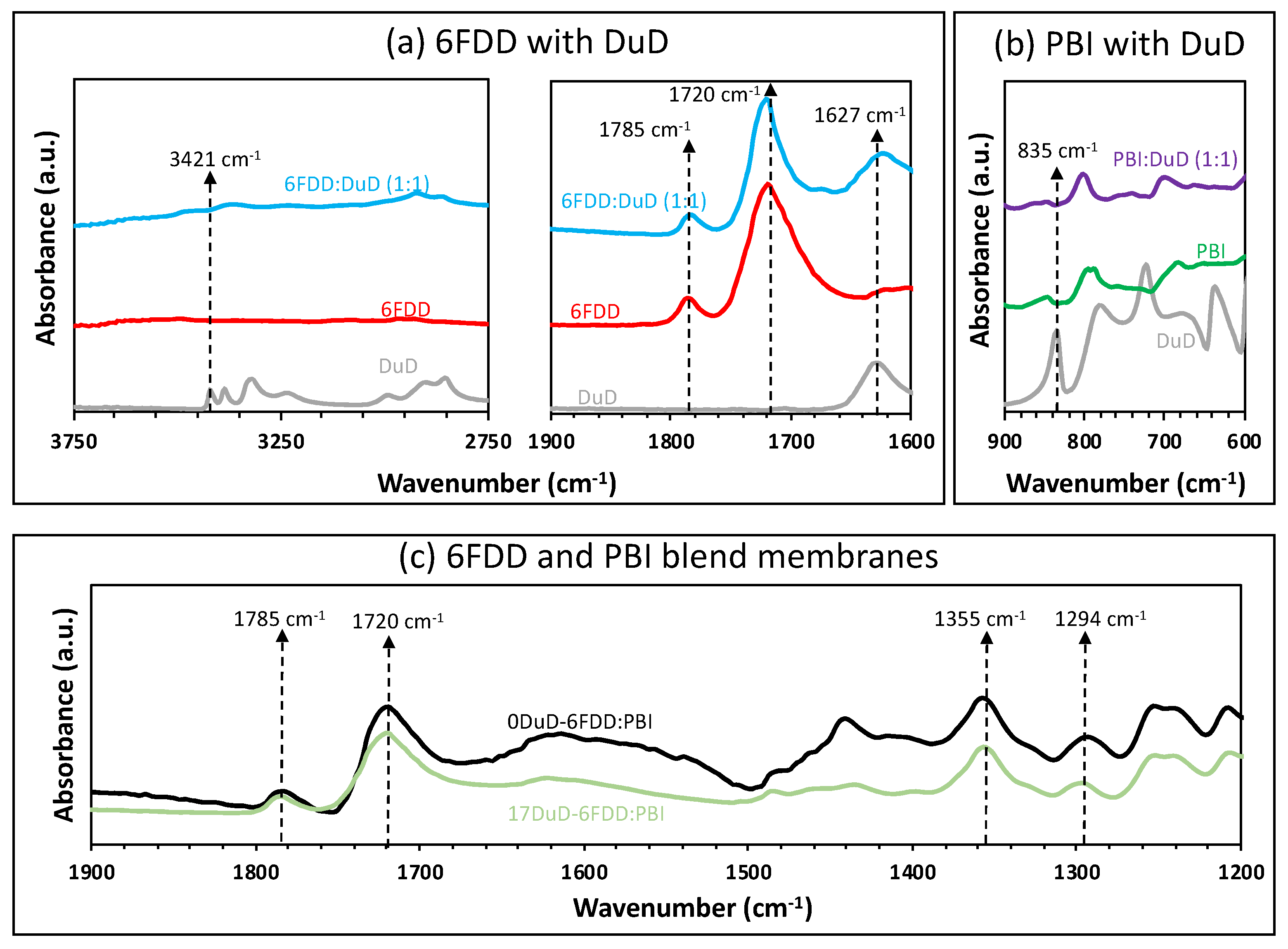
3.2.1. FTIR Spectroscopy

The improved compatibility between the polymers can be explained by considering the interfacial localization of the small molecule, as was previously reported [12]. To study the chemical interactions between the polymers and DuD, membranes that comprised 6FDD:DuD and PBI:DuD in a 1:1 weight ratio were prepared. These membranes were then annealed at 100 °C under vacuum for 5 days to remove the casting solvent DMAc. The infrared spectra of the membranes (Figure 4a,b and Figure S6 in Supplementary Information for entire IR spectra) showed no major IR peak shifts or changes for the pure polymers after the thermal treatment. Similarly, even when the polymers were in contact with DuD, no peaks showed significant shifts that would indicate the formation of significant hydrogen bonding between the polymers and the compatibilizer. Peaks corresponding to the stretching and bending of the primary amine of DuD (s = 3421 cm−1, b = 1627 cm−1, Figure 4a), the symmetric and asymmetric imide carbonyl stretching of 6FDD (ss = 1720 cm−1, sa = 1785 cm−1, Figure 4a), and the amine wagging of PBI (w = 835 cm−1, Figure 4b) did not show noticeable shifts due to hydrogen bonding interaction of these moieties with DuD [12]. It was theorized, however, that some hydrogen bonding interactions could still restrict the aggregation and coalescence of the 6FDD domains within the polymer blend membrane matrix [11,12], which may result in compatible polymer blends with smaller and more uniform 6FDD domains. From the analysis of the morphologies of the compatibilized polymer blend membranes from this work, shown in Figure 2, it is plausible to conclude that a small degree of hydrogen bonding, which could be masked in the spectra, may have contributed to the formation of the morphologies of the compatibilized polymer blends. A comparison of the IR spectrum of 0DuD-6FDD: PBI to that of 17DuD-6FDD:PBI (Figure 4c), however, showed no significant hydrogen bonding in the compatibilized polymer blend.
The IR spectra shown in Figure 4a and in Figure S7 in the Supporting Information also show that during the membrane preparation process, DuD was not involved in nucleophilic attack to the imide carbonyl of 6FDD that could result in a ring opening. The IR peak corresponding to the imide carbonyl stretch remained unchanged.

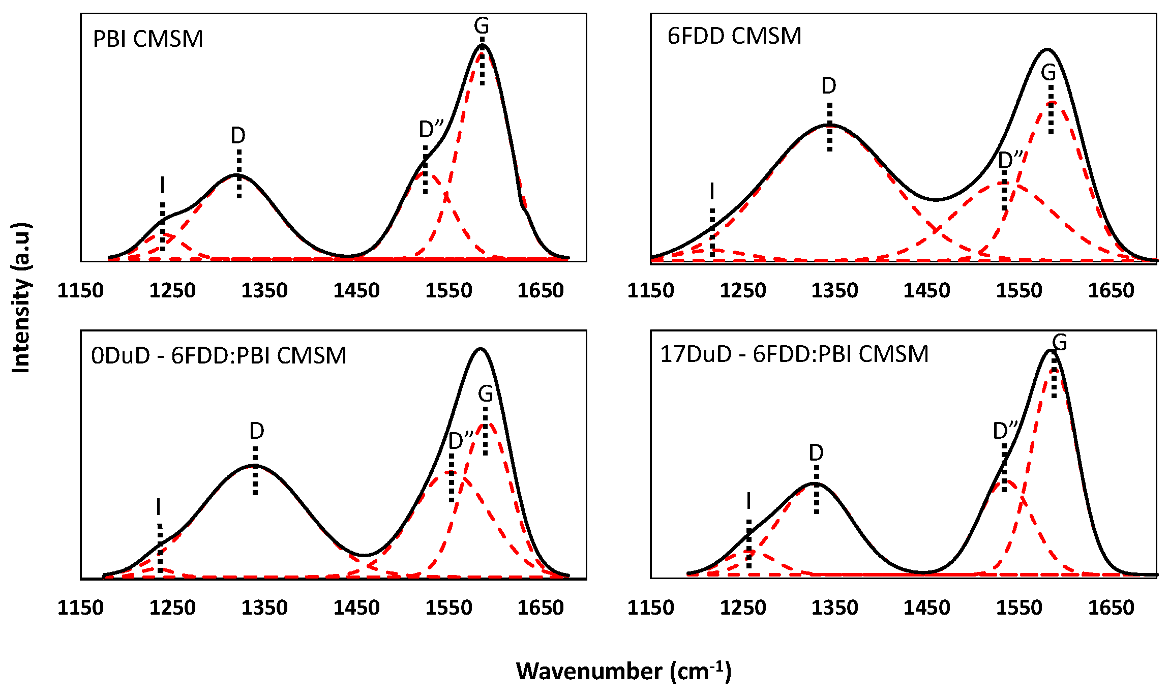
3.2.2. Raman Spectroscopy

Figure 5 shows the deconvoluted Raman spectra of the carbonized polymers as well as of the non-compatibilized and compatibilized carbonized polymer blends. The deconvolution was conducted according to a previously reported procedure for amorphous carbons [59]. Typical Raman shifts for carbon materials appeared at 1350 cm−1 and from 1580 cm−1 to 1600 cm−1, which corresponded to the D and G bands, respectively [60,61]. The D band results from the presence of sp3 carbons or an increased amount of boundary in the sample [61], whereas the G band arises from graphitic carbons [1,59,60,61,62]. In addition, two more peaks, I and D″, appeared in all the spectra. The I band is visible from around 1180 cm−1 to 1290 cm−1 and results from either the disorder in the graphitic lattice or the bonds between sp2–sp3 carbons [63,64]. The D″ band results from both C-H bond vibrations and semicircle ring stretch vibrations of benzene rings [65]. The intensity ratios of the D and G bands (ID/IG) indicate the amount of graphitization of the material.
Table 2 summarizes the ID/IG ratios of the carbonized membranes. The ID/IG ratios of the peak heights of PBI and 6FDD CMSMs were 0.40 and 0.85, respectively, whereas the CMSMs from the polymer blends exhibited intermediate ID/IG ratios. Interestingly, the CMSM from the compatibilized polymer blend 17DuD-6FDD:PBI showed a higher degree of graphitization than the CMSM from the non-compatibilized blend. This improvement in the graphitic content of the CMSM obtained from the compatibilized polymer blend was attributed to the stabilized microstructure induced by the compatibilizer, DuD. The ID/IG ratios can also be used to estimate the graphitic crystallite size and to understand the effects of compatibilization in the CMSM structure. The correlation of the crystallite size along the a axis (La, in Å) of graphite to ID/IG ratios was reported by Tuinstra in a La vs. ID/IG plot [61]. In this plot, the La values of several carbon materials were obtained from X-ray diffraction data and then plotted against their ID/IG ratios calculated from Raman spectroscopy. A linear fitting applied to this plot then provided the equation La = 44 × (ID/IG)−1 that was used to estimate the crystallite size in the a-axis direction [66,67]. An estimation of the La values from the ID/IG ratios of the CMSMs from this work is shown in Table 2. The La values show that the PBI-derived CMSMs exhibited graphitic particles twice the size of those derived from 6FDD. This may indicate that the PBI-derived CMSMs contained larger continuous layers than the 6FDD-derived CMSMs, which contained shorter layers. It also suggests that the distance between the layers in the graphitic domains in 6FDD-derived CMSMs may be larger than in those from PBI-derived CMSMs [61] due to the increased boundary and disorder between the layers of the smaller particle domains. Smaller graphitic domains could also result in inefficient stacking that increases gas diffusion at the expense of selectivity [68]. The La values also show that the presence of DuD in the polymer blend affected the formation of the graphitic domains of the CMSMs. The data suggest that DuD may have induced the formation of larger graphitic layers or was incorporated into the layers, since the resulting domains in the CMSM from the compatibilized polymer blends were larger than those from the non-compatibilized polymer blends. If DuD had no effect on the graphitic domains during the carbonization of the compatibilized polymers, then the size of the graphitic domains would be similar to those of the CMSM from the non-compatibilized polymer blend, but this was not the case, as the CMSM from the compatibilized polymer blend had 60% larger graphitic domains than the CMSM from the non-compatibilized polymer blend.

3.3. Gas Permeation Properties of Membranes

3.3.1. Gas Permeation of Polymer Blend Membranes

Table 3 summarizes the gas permeability performances of the polymer membranes. PBI had a high H2/CO2 selectivity and low H2 permeability, while 6FDD was highly permeable for H2 but possessed a low H2/CO2 selectivity. The measured permeabilities and selectivities for all the blend membranes lay between those of the pure polymer membranes. The compatibilized polymer blends, however, showed improvements in both H2 permeability and H2/CO2 selectivity. Increasing the compatibilizer ratio from 0 wt% to 17 wt% resulted in enhanced permeability and H2/CO2 selectivity by 700% and 250%, respectively. The reason for the H2 permeability increase can be attributed, in part, to the gas transport pathways formed due to the phase transitions that DuD underwent during the annealing process and to the membrane microstructure [12].
During the annealing process, DuD evaporates from the membrane, leaving behind new microscopic diffusional paths that improve the hydrogen diffusion. This is plausible since the annealing temperature is lower than the Tg of the polymers but high enough to induce some microscopic segmental motion in the polymer chains that enhances hydrogen’s mobility between the polymer chains [33]. Since the membrane retains a high H2/CO2 selectivity at high DuD loadings, it can be concluded that such segmental motions are in the sub-angstrom scale since only hydrogen experiences an increase in permeability [33].
The improvements in the H2/CO2 selectivity can also be described in terms of the membrane microstructure. The higher DuD concentration resulted in an improved compatibility between the polymers, as described earlier from the analyses of the SEM images (Figure 2) and the domain size distributions (Figure 3). The graphical representations of the blend membrane microstructure shown in Figure 6 can be used to further elaborate upon the effect of compatibilization on gas permeation. The arrows in Figure 6 represent gas transport pathways through the membrane cross-section from the upstream side (left) to the downstream side (right). The less selective pathway (blue arrow in Figure 6) is a gas transport pathway formed only by the less selective material (6FDD) through the membrane cross-section. Therefore, gas molecules will have the freedom to pass through either pathway, where the non-selective gas transport pathway is the most favorable due to less resistance to gas molecule diffusion. However, the probability of the existence of these non-selective pathways decreases with the increasing the compatibilizer loading (enhanced compatibility) and therefore increasing the selectivity (green arrow in Figure 6).
Since the aggregation of the domains of the dispersed phase (6FDD) was suppressed with increasing the compatibilizer concentration in the blend membranes, the 17DuD-6FDD:PBI membrane then possessed the lowest probability of existence of unselective pathways, followed by the 9 wt% and 5 wt% DuD-containing membranes. Furthermore, the number of selective polymer (PBI) passages in a unit length across the cross-section of each membrane can also be used to explain the gas permeation properties of these membranes. In theory, a higher number of selective paths (fn) promotes higher selectivity, while a lower thickness of selective paths (t) promotes higher gas flux. For example, the thickness of the PBI selective layer at t0 (no DuD in the blend) would be larger than at t17 (17% DuD load in the blend), resulting in lower gas flux across the membrane at t0 than at t17. Therefore, the most compatible polymer blend (17DuD-6FDD:PBI) is expected to have the highest performance from the set of membranes tested in this work. The experimental gas permselectivities shown in Table 3 are in good agreement with this explanation, supporting our hypothesis that the gas transport properties of the polymer blend membranes from this work are governed by their morphological features.

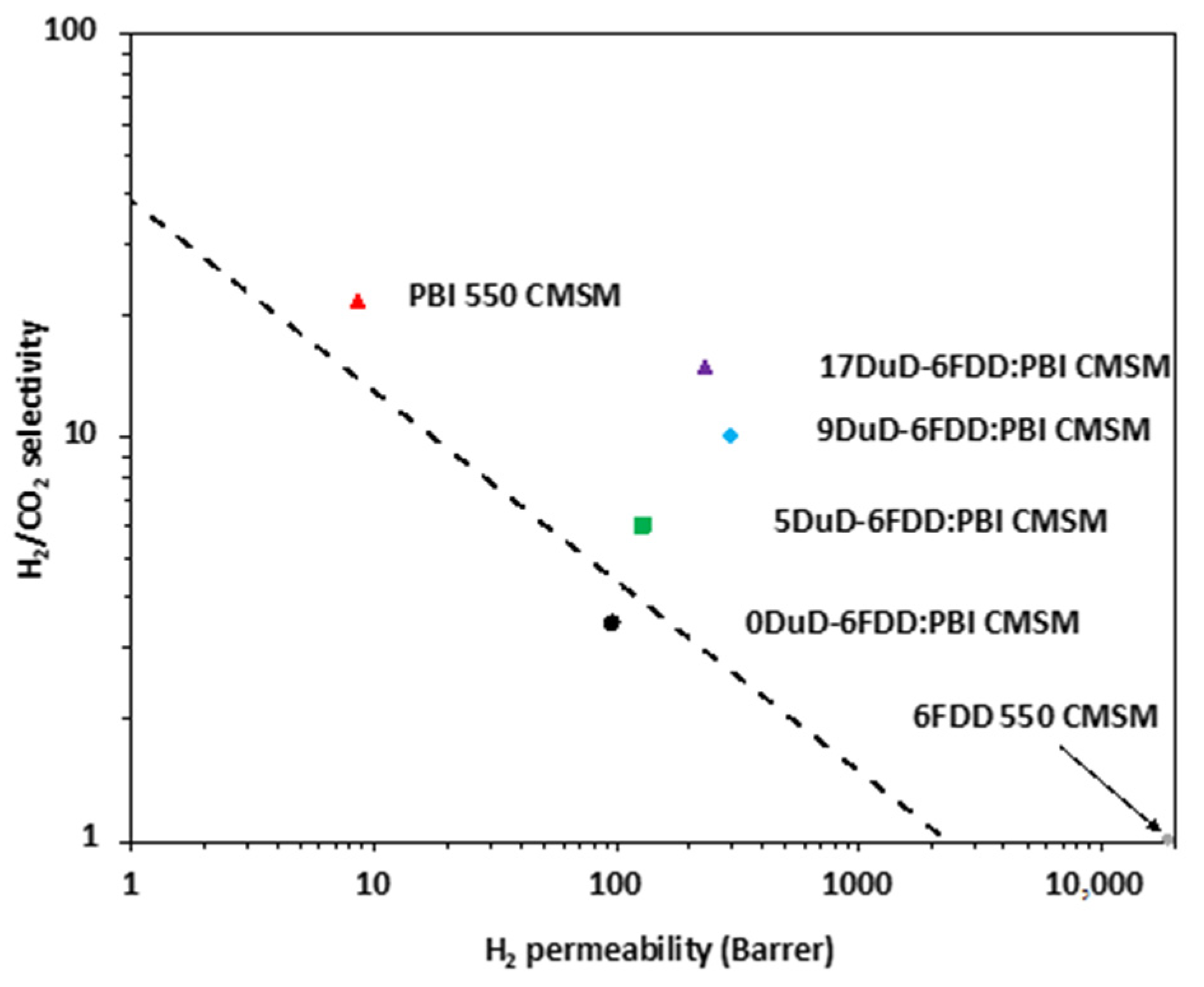
3.3.2. Gas Permeation of CMSMs from Polymer Blends

Table 4 summarizes the gas permeation performance of the carbon–carbon composite membranes. Even after carbonization, PBI remained the least permeable and most selective component, while 6FDD remained the most permeable and least selective component. The PBI CMSM showed only a 5-fold increase in permeability from the precursor polymer membrane, whereas the 6FDD CMSM exhibited a 190-fold increase in permeability. This can be attributed to the thermal stabilities of the polymers at the carbonization temperature of 550 °C. To understand the effect of the thermal stabilities of the polymers, TGA analyses of the two pure polymers and the compatibilized and non-compatibilized polymer blends, shown in Figure 7, were performed following the carbonization temperature protocol of the CMSMs: from 70 °C to 250 °C at 15 °C/min (zone A), from 250 °C to 535 °C at 4 °C/min (zone B), from 535 °C to 550 °C at 0.25 °C/min (zone C), and an isothermal period at 550 °C for 2 h (zone D). Figure 7 shows that during carbonization, 6FDD underwent a mass loss of 22 wt% when the temperature reached 550 °C, whereas PBI lost 3 wt% only. As was recently observed, PBI polymer undergoes very little weight loss up to temperatures of 400 °C to 500 °C due to its high carbon content [33], but the transition to 550 °C may just have started the formation of graphitic domains that slightly increased its permeability without sacrificing selectivity. For 6FDD, however, the initial 22 wt% loss may have imparted more porosity to the CMSM, resulting in high permeability for both gasses at the expense of reduced selectivity.
At the end of the carbonization protocol (2 h at 550 °C), 6FDD lost 42 wt% of its mass and PBI lost 10 wt%. The PBI weight loss can be attributed, in part, to the release of adsorbed water, trapped DMAc, and the full conversion of trace amounts of the PBI prepolymer into pure PBI [33]. Similar weight loss trends have also been observed by other researchers [69]. The high weight retention of PBI and the low weight retention of 6FDD resulted in two unique materials with different gas permeability properties embedded in the carbon–carbon composite membranes, where one carbon phase was highly permeable (dispersed carbon phase from 6FDD) and the other was highly selective (continuous carbon phase from PBI). Figure 7 also shows that the blends had an intermediate weight retention of 70 wt% at the end of the carbonization protocol.
Table 4 shows that the gas permeation properties of the CMSMs showed a trend analogous to that of the precursor membranes, and the carbon membranes derived from the polymer blend precursors showed intermediate permeabilities and selectivities that lay between those of 6FDD and PBI. Table 4 also shows that the H2/CO2 selectivities of the CMSMs from the blends increased significantly with increasing the compatibilizer concentration, reaching a selectivity close to that of PBI at 17 wt% DuD loading. In the absence of DuD, the selectivity of the CMSMs from the blends was low, suggesting the formation of large pores or a non-continuity of the selective layer that was inherited from the uncompatibilized immiscible polymer blend microstructure.
The gas separation performance of the CMSMs from this work was compared to that of other membranes in a Robeson plot [4], as shown in Figure 8. Both the PBI and 6FDD CMSMs surpassed the upper bound due to the high selectivity and superior permeability of the two materials, respectively. More importantly, the composite membranes derived from the compatibilized polymer precursors surpassed the upper bound, approaching the commercially attractive upper right-hand quadrant with increasing the DuD concentration.
To further understand the effect of the carbonization temperature on the gas separation performance of these membranes, the carbonization temperature was increased from 550 °C to 675 °C to narrow the pores and to increase the selectivity. Typically, a decrease in permeability was observed, coupled with an increase in selectivity as the final carbonization temperature increased. This was mainly due to the increase in the number of ultramicropores being formed at high carbonization temperatures [24]. Subjecting a 9DuD-6FDD:PBI membrane to a final carbonization temperature of 675 °C resulted in both the hydrogen and carbon dioxide permeabilities decreasing while the H2/CO2 selectivity of the membrane increased significantly. This can be seen in Table 5 when comparing the permeabilities of the membranes carbonized at 550 °C.

3.4. Understanding the Applicability of Gas Permeation Models for Precursors and CMSMs

As described in the experimental section, gas permeability models were used to construct plots of H2 permeability versus the carbonized 6FDD volume fraction (Figure 9). The volume fractions of the carbonized polymers were determined using the densities of carbonized PBI (1.24 g cm−3) and 6FDD (1.29 g cm−3). The dotted line in Figure 9 predicts the behavior of the two materials in a miscible blend (carbonized PBI and 6FDD in this study). The positions of data points reflect the relationship between the morphology of the carbon–carbon composite membranes and the permeability models. Figure 9 shows that the gas transport properties of the carbon membrane derived from the non-compatibilized polymer blend could be best described using the Maxwell model (heterogeneous material). The gas transport properties of the carbon–carbon composite membranes derived from the compatibilized polymer blends, however, approached the behavior of miscible polymers (homogeneous material) with increasing the compatibilizer concentration. This behavior is expected, since the properties of CMSMs strongly depend on the properties of the polymer precursor (e.g., a high free-volume polymer yields a highly permeable CMSM). In the case of the compatibilized polymer blend, the morphology of the blend approached that of a homogeneous material, whereas the non-compatibilized blend resembled that of an heterogeneous material. Therefore, the gas transport properties of the CMSMs from the compatibilized blend should approach those for homogeneous materials, and the properties of the CMSMs from the non-compatibilized blend should lie close to those derived from the Maxwell model for heterogeneous materials, as shown in Figure 9.

4. Conclusions

The compatibilization of immiscible polymers with the addition of small amounts of the small molecule DuD resulted in the control of the morphology of both the polymer blend and the resulting CMSMs. Spectroscopic characterization suggests that compatibilization with DuD may contribute to the formation of larger graphitic domains in the CMSM derived from the compatibilized polymer blend, showing La values similar to that of pure PBI-derived CMSMs. The presence of larger graphitic domains in the CMSM from the compatibilized polymer blend minimizes the formation of voids in the continuous layer of the selective polymer and therefore increases the H2/CO2 selectivity. A significant result is that the morphology of the compatibilized polymer blend was preserved during the carbonization process, which led to CMSMs composed of two different carbon domains being obtained, with each domain contributing its permeation properties to the overall performance of the carbon blend. This combination of performances improved the H2 permeabilities of the CMSMs, surpassing the 2008 Robeson upper bound for H2/CO2 separations. This work shows that this approach could lead to the formation of a new class of CMSMs that can be derived from immiscible polymer blend precursors economically and conveniently.

Supplementary Materials

The following supporting information can be downloaded at: https://www.mdpi.com/article/10.3390/separations11040108/s1, [58,70,71,72], Figure S1: Synthesis route for 6FDA-DAM:DABA [3:2] (6FDD); Figure S2: 1H-NMR spectrum of 6FDD in dimethyl sulfoxide (DMSO-d6); Figure S3: Differential scanning calorimetry curve of 6FDD; Figure S4: Cross-section SEM images of: (a) PBI, (b) 6FDD, (c) PBI CMSM, and (d) 6FDD CMSM; Figure S5: Cross-section SEM images of immiscible polymer blend membranes: (a) 0DuD-6FDD:PBI, (b) 5DuD-6FDD:PBI, (c) 9DuD-6FDD:PBI, (d) 17DuD-6FDD:PBI; Figure S6: ATR-FTIR spectra of the prepared membranes: (a) 6FDD:DuD, (b) PBI:DuD, (c) 6FDD:PBI; Figure S7: FTIR spectra of 6FDD, DD, and 6FDD:DD (1:1); Equations for the calculation of permeability from different transport models.

Author Contributions

Conceptualization, C.K., J.P.F. and K.J.B.J.; methodology, C.K. and J.P.F.; validation, J.P.F. and K.J.B.J.; formal analysis, C.K., J.P.F. and K.J.B.J.; investigation, N.P.P. and S.P.; resources, J.P.F., K.J.B.J. and I.H.M.; data curation, C.K.; writing—original draft preparation, C.K.; writing—review and editing, E.V.P., J.P.F. and K.J.B.J.; supervision, J.P.F. and K.J.B.J.; project administration, J.P.F.; funding acquisition, J.P.F., K.J.B.J. and I.H.M. All authors have read and agreed to the published version of the manuscript.

Funding

This research was funded by the National Science Foundation (grant nos. CBET-1403950, CBET-1917747).

Data Availability Statement

Data are contained within the article.

Acknowledgments

This work was supported by the National Science Foundation (grant nos. CBET-1403950, CBET-1917747). The assistance of Nimali Abeykoon and Sahila Perananthan is greatly acknowledged.

Conflicts of Interest

The authors declare no conflict of interest.

Abbreviations

αIdeal gas selectivity
pDifferential gas pressure across the membrane
1H-NMR Proton nuclear magnetic resonance
6FDA4,4-(hexafluoroisopropylidene)diphthalic anhydride
6FDD6FDA-DAM:6FDA-DABA [3:2] polymer
AMembrane exposed area
ÅAngstrom
ATR-FTIRAttenuated total reflectance Fourier transform infrared
CMSMCarbon molecular sieve membrane
DRaman band from disordered domains
DABA3,5-diaminobenzoic acid
DAM2,4,6-trimethyl-1,3-phenylenediamine
DMAcN,N-dimethylacetamide
DMSO-d6 Deuterated dimethyl sulfoxide
DSCDifferential scanning calorimeter
DuD2,3,5,6-tetramethyl-1,4-phenylenediamine (durene diamine)
EBMEquivalent box model of gas transport in composite materials
fnThe average number of PBI passages in a unit length at n% DuD loading
GRaman band from graphitic domains
IDIntensity from disordered domains
IGIntensity from graphitic domains
JFlow rate
kDaKilodalton
LMembrane thickness
LaCrystallite size along the a axis
LiClLithium chloride
MwMolecular weight
NMPN-methyl pyrrolidone
PBIPolybenzimidazole
PDIPolydispersity index
PPermeability
SEMScanning electron microscopy
TGAThermogravimetric analysis
THFTetrahydrofuran
TMSTetramethylsilane
tnAverage thickness of PBI passages in membrane at n% DuD loading
UHPUltra-high purity

References

  1. Baker, R.W.; Low, B.T. Gas separation membrane materials: A perspective. Macromolecules 2014, 47, 6999–7013. [Google Scholar] [CrossRef]
  2. Bernardo, P.; Drioli, E.; Golemme, G. Membrane gas separation: A review/state of the art. Ind. Eng. Chem. Res. 2009, 48, 4638–4663. [Google Scholar] [CrossRef]
  3. Baker, R.W.; Lokhandwala, K. Natural gas processing with membranes: An overview. Ind. Eng. Chem. Res. 2008, 47, 2109–2121. [Google Scholar] [CrossRef]
  4. Robeson, L.M. The upper bound revisited. J. Membr. Sci. 2008, 320, 390–400. [Google Scholar] [CrossRef]
  5. Tanco, M.L.; Tanaka, D.P. Recent advances on carbon molecular sieve membranes (CMSMs) and reactors. Processes 2016, 4, 29. [Google Scholar] [CrossRef]
  6. Kim, S.-J.; Kwon, Y.; Kim, D.; Park, H.; Cho, Y.H.; Nam, S.-E.; Park, Y.-I. A review on polymer precursors of carbon molecular sieve membranes for olefin/paraffin separation. Membranes 2021, 11, 482. [Google Scholar] [CrossRef]
  7. Salleh, W.N.W.; Ismail, A.F. Carbon membranes for gas separation processes: Recent progress and future perspective. J. Membr. Sci. Res. 2015, 1, 2–15. [Google Scholar]
  8. Williams, P.J.; Koros, W.J. Gas Separation by Carbon Membranes. In Advanced Membrane Technology and Applications; Li, N.N., Fane, A.G., Ho, W.S.W., Matsuura, T., Eds.; John Wiley & Sons, Incorporated: New York, NY, USA, 2008; pp. 599–631. [Google Scholar]
  9. Rahimalimamaghani, A.; Ramezani, R.; Tanaka, D.A.P.; Gallucci, F. Carbon molecular sieve membranes for selective CO2/CH4 and CO2/N2 separation: Experimental study, optimal process design, and economic analysis. Ind. Eng. Chem. Res. 2023, 62, 19116–19132. [Google Scholar] [CrossRef]
  10. Ngamou, P.H.T.; Ivanova, M.E.; Guillon, O.; Meulenberg, W.A. High-performance carbon molecular sieve membranes for hydrogen purification and pervaporation dehydration of organic solvents. J. Mater. Chem. A 2019, 7, 7082–7091. [Google Scholar] [CrossRef]
  11. Panapitiya, N.P.; Wijenayake, S.N.; Huang, Y.; Bushdiecker, D.; Nguyen, D.; Ratanawanate, C.; Kalaw, G.J.; Gilpin, C.J.; Musselman, I.H.; Balkus, K.J.; et al. Stabilization of immiscible polymer blends using structure directing metal-organic frameworks (MOFs). Polymer 2014, 55, 2028–2034. [Google Scholar] [CrossRef]
  12. Panapitiya, N.P.; Wijenayake, S.N.; Nguyen, D.D.; Huang, Y.; Musselman, I.H.; Balkus, K.J.; Ferraris, J.P. Gas separation membranes derived from high-performance immiscible polymer blends compatibilized with small molecules. ACS Appl. Mater. Interfaces 2015, 7, 18618–18627. [Google Scholar] [CrossRef]
  13. Bhuwania, N.; Labreche, Y.; Achoundong, C.S.K.; Baltazar, J.; Burgess, S.K.; Karwa, S.; Xu, L.; Henderson, C.L.; Williams, P.J.; Koros, W.J. Engineering substructure morphology of asymmetric carbon molecular sieve hollow fiber membranes. Carbon 2014, 76, 417–434. [Google Scholar] [CrossRef]
  14. Hatori, H.; Kobayashi, T.; Hanzawa, Y.; Yamada, Y.; Iimura, Y.; Kimura, T.; Shiraishi, M. Mesoporous carbon membranes from polyimide blended with poly(ethylene glycol). J. Appl. Polym. Sci. 2001, 79, 836–841. [Google Scholar] [CrossRef]
  15. Gilron, J.; Soffer, A. Knudsen diffusion in microporous carbon membranes with molecular sieving character. J. Membr. Sci. 2002, 209, 339–352. [Google Scholar] [CrossRef]
  16. Hu, L.; Bui, V.T.; Krishnamurthy, A.; Fan, S.; Guo, W.; Pal, S.; Chen, X.; Zhang, G.; Ding, Y.; Singh, R.P.; et al. Tailoring sub-3.3 Å ultramicropores in advanced carbon molecular sieve membranes for blue hydrogen production. Sci. Adv. 2022, 8, eabl8160. [Google Scholar] [CrossRef] [PubMed]
  17. Kim, Y.K.; Park, H.B.; Lee, Y.M. Gas separation properties of carbon molecular sieve membranes derived from polyimide/polyvinylpyrrolidone blends: Effect of the molecular weight of polyvinylpyrrolidone. J. Membr. Sci. 2005, 251, 159–167. [Google Scholar] [CrossRef]
  18. Tin, P.S.; Xiao, Y.; Chung, T.S. Polyimide-carbonized membranes for gas separation: Structural, composition, and morphological control of precursors. Sep. Purif. Rev. 2006, 35, 285–318. [Google Scholar] [CrossRef]
  19. Park, H.B.; Kim, Y.K.; Lee, J.M.; Lee, S.Y.; Lee, Y.M. Relationship between chemical structure of aromatic polyimides and gas permeation properties of their carbon molecular sieve membranes. J. Membr. Sci. 2004, 229, 117–127. [Google Scholar] [CrossRef]
  20. Briceño, K.; Montané, D.; Garcia-Valls, R.; Iulianelli, A.; Basile, A. Fabrication variables affecting the structure and properties of supported carbon molecular sieve membranes for hydrogen separation. J. Membr. Sci. 2012, 415–416, 288–297. [Google Scholar] [CrossRef]
  21. Fu, S.; Wenz, G.B.; Sanders, E.S.; Kulkarni, S.S.; Qiu, W.; Ma, C.; Koros, W.J. Effects of pyrolysis conditions on gas separation properties of 6FDA/DETDA: DABA(3:2) derived carbon molecular sieve membranes. J. Membr. Sci. 2016, 520, 699–711. [Google Scholar] [CrossRef]
  22. Favvas, E.P.; Kouvelos, E.P.; Romanos, G.E.; Pilatos, G.I.; Mitropoulos, A.C.; Kanellopoulos, N.K. Characterization of highly selective microporous carbon hollow fiber membranes prepared from a commercial co-polyimide precursor. J. Porous Mater. 2008, 15, 625–633. [Google Scholar] [CrossRef]
  23. Hosseini, S.S.; Omidkhah, M.R.; Moghaddam, A.Z.; Pirouzfar, V.; Krantz, W.B.; Tan, N.R. Enhancing the properties and gas separation performance of PBI–polyimides blend carbon molecular sieve membranes via optimization of the pyrolysis process. Sep. Purif. Technol. 2014, 122, 278–289. [Google Scholar] [CrossRef]
  24. Steel, K.M.; Koros, W.J. An investigation of the effects of pyrolysis parameters on gas separation properties of carbon materials. Carbon 2005, 43, 1843–1856. [Google Scholar] [CrossRef]
  25. Liu, Z.; Qiu, W.; Quan, W.; Koros, W.J. Advanced carbon molecular sieve membranes derived from molecularly engineered cross-linkable copolyimide for gas separations. Nat. Mater. 2023, 22, 109–116. [Google Scholar] [CrossRef]
  26. Fuertes, A.B.; Centeno, T.A. Carbon molecular sieve membranes from polyetherimide. Micropor. Mesopor. Mat. 1998, 26, 23–26. [Google Scholar] [CrossRef]
  27. Tseng, H.-H.; Shih, K.; Shiu, P.-T.; Wey, M.-Y. Influence of support structure on the permeation behavior of polyetherimide-derived carbon molecular sieve composite membrane. J. Membr. Sci. 2012, 405–406, 250–260. [Google Scholar] [CrossRef]
  28. Salleh, W.N.W.; Ismail, A.F. Effect of stabilization temperature on gas permeation properties of carbon hollow fiber membrane. J. Appl. Polym. Sci. 2013, 127, 2840–2846. [Google Scholar] [CrossRef]
  29. Teixeira, M.; Campo, M.C.; Tanaka, D.A.P.; Tanco, M.A.L.; Magen, C.; Mendes, A. Composite phenolic resin-based carbon molecular sieve membranes for gas separation. Carbon 2011, 49, 4348–4358. [Google Scholar] [CrossRef]
  30. Teixeira, M.; Rodrigues, S.C.; Campo, M.; Tanaka, D.A.P.; Tanco, M.A.L.; Madeira, L.M.; Sousa, J.M.; Mendes, A. Boehmite-phenolic resin carbon molecular sieve membranes—Permeation and adsorption studies. Chem. Eng. Res. Des. 2014, 92, 2668–2680. [Google Scholar] [CrossRef]
  31. Wei, W.; Qin, G.; Hu, H.; You, L.; Chen, G. Preparation of supported carbon molecular sieve membrane from novolac phenol–formaldehyde resin. J. Membr. Sci. 2007, 303, 80–85. [Google Scholar] [CrossRef]
  32. Nie, J.; Okada, F.; Kita, H.; Tanaka, K.; Mihara, T.; Kondo, D.; Yamashita, Y.; Yahagi, N. Fabrication of carbon molecular sievemembranes supported on a novel porous carbon fiber. Energy Fuels 2022, 36, 7147–7157. [Google Scholar] [CrossRef]
  33. Perez, E.V.; Ferraris, J.P.; Balkus, K.J.; Musselman, I.H. Effect of the annealing temperature of polybenzimidazole membranes in high pressure and high temperature H2/CO2 gas separations. J. Membr. Sci. 2023, 677, 121619. [Google Scholar] [CrossRef]
  34. Asano, A.; Takegoshi, K. Polymer Blends and Miscibility. In Solid State NMR of Polymers; Ando, I., Asakura, T., Eds.; Elsevier Science: Amsterdam, The Netherlands, 1998; pp. 351–414. [Google Scholar]
  35. Hosseini, S.S.; Chung, T.S. Carbon membranes from blends of PBI and polyimides for N2/CH4 and CO2/CH4 separation and hydrogen purification. J. Membr. Sci. 2009, 328, 174–185. [Google Scholar] [CrossRef]
  36. Dickinson, L.C.; Yang, H.; Chu, C.-W.; Stein, R.S.; Chien, J.C.W. Limits to compatibility in poly(x-methylstyrene)/Poly (2,6-dimethylphenylene oxide) blends by NMR. Macromolecules 1987, 20, 1757–1760. [Google Scholar] [CrossRef]
  37. Kaplan, D.S. Structure–property relationships in copolymers to composites: Molecular interpretation of the glass transition phenomenon. J. Appl. Polym. Sci. 1976, 20, 2615–2629. [Google Scholar] [CrossRef]
  38. Fu, Y.-J.; Hu, C.-C.; Lin, D.-W.; Tsai, H.-A.; Huang, S.-H.; Hung, W.-S.; Lee, K.-R.; Lai, J.-Y. Adjustable microstructure carbon molecular sieve membranes derived from thermally stable polyetherimide/polyimide blends for gas separation. Carbon 2017, 113, 10–17. [Google Scholar] [CrossRef]
  39. Kyotani, T. Control of pore structure in carbon. Carbon 2000, 38, 269–286. [Google Scholar] [CrossRef]
  40. Lee, H.J.; Suda, H.; Haraya, K. Preparation of carbon membranes derived from polymer blends in the presence of a thermally labile polymer. Sep. Sci. Technol. 2007, 42, 59–71. [Google Scholar] [CrossRef]
  41. Kim, Y.K.; Park, H.B.; Lee, Y.M. Carbon molecular sieve membranes derived from thermally labile polymer containing blend polymers and their gas separation properties. J. Membr. Sci. 2004, 243, 9–17. [Google Scholar] [CrossRef]
  42. Saufi, S.M.; Ismail, A.F. Fabrication of carbon membranes for gas separation––A review. Carbon 2004, 42, 241–259. [Google Scholar] [CrossRef]
  43. Centeno, T.A.; Fuertes, A.B. Carbon molecular sieve membranes derived from a phenolic resin supported on porous ceramic tubes. Sep. Purif. Technol. 2001, 25, 379–384. [Google Scholar] [CrossRef]
  44. Tin, P.S.; Chung, T.-S.; Hill, A.J. Advanced fabrication of carbon molecular sieve membranes by nonsolvent pretreatment of precursor polymers. Ind. Eng. Chem. Res. 2004, 43, 6476–6483. [Google Scholar] [CrossRef]
  45. Perez, E.; Karunaweera, C.; Musselman, I.; Balkus, K.; Ferraris, J. Origins and evolution of inorganic-based and MOF-based mixed-matrix membranes for gas separations. Processes 2016, 4, 32. [Google Scholar] [CrossRef]
  46. Lua, A.C.; Shen, Y. Preparation and characterization of polyimide–silica composite membranes and their derived carbon–silica composite membranes for gas separation. Chem. Eng. J. 2013, 220, 441–451. [Google Scholar] [CrossRef]
  47. Zhang, B.; Wang, T.; Wu, Y.; Liu, Q.; Liu, S.; Zhang, S.; Qiu, J. Preparation and gas permeation of composite carbon membranes from poly(phthalazinone ether sulfone ketone). Sep. Purif. Technol. 2008, 60, 259–263. [Google Scholar] [CrossRef]
  48. Rao, P.S.; Wey, M.-Y.; Tseng, H.-H.; Kumar, I.A.; Weng, T.-H. A comparison of carbon/nanotube molecular sieve membranes with polymer blend carbon molecular sieve membranes for the gas permeation application. Micropor. Mesopor. Mat. 2008, 113, 499–510. [Google Scholar] [CrossRef]
  49. Richter, H.; Voss, H.; Kaltenborn, N.; Kämnitz, S.; Wollbrink, A.; Feldhoff, A.; Caro, J.; Roitsch, S.; Voigt, I. High-flux carbon molecular sieve membranes for gas separation. Angew. Chem. Int. Ed. 2017, 56, 7760–7763. [Google Scholar] [CrossRef]
  50. Hayashi, J.-I.; Mizuta, H.; Yamamoto, M.; Kusakabe, K.; Morooka, S. Pore size control of carbonized BPDA-pp′ ODA polyimide membrane by chemical vapor deposition of carbon. J. Membr. Sci. 1997, 124, 243–251. [Google Scholar] [CrossRef]
  51. Robeson, L.M. Polymer Blends: A Comprehensive Review; Hanser: Cincinnati, OH, USA, 2007. [Google Scholar]
  52. Panapitiya, N.; Wijenayake, S.; Nguyen, D.; Karunaweera, C.; Huang, Y.; Balkus, K.; Musselman, I.; Ferraris, J. Compatibilized immiscible polymer blends for gas separations. Materials 2016, 9, 643. [Google Scholar] [CrossRef]
  53. Omole, I.C.; Miller, S.J.; Koros, W.J. Increased molecular weight of a cross-linkable polyimide for spinning plasticization resistant hollow fiber membranes. Macromolecules 2008, 41, 6367–6375. [Google Scholar] [CrossRef]
  54. Grubb, T.L.; Ulery, V.L.; Smith, T.J.; Tullos, G.L.; Yagci, H.; Mathias, L.J.; Langsam, M. Highly soluble polyimides from sterically hindered diamines. Polymer 1999, 40, 4279–4288. [Google Scholar] [CrossRef]
  55. Fu, S.; Sanders, E.S.; Kulkarni, S.S.; Koros, W.J. Carbon molecular sieve membrane structure–property relationships for four novel 6FDA based polyimide precursors. J. Membr. Sci. 2015, 487, 60–73. [Google Scholar] [CrossRef]
  56. Pye, D.; Hoehn, H.; Panar, M. Measurement of gas permeability of polymers. I. Permeabilities in constant volume/variable pressure apparatus. J. Appl. Polym. Sci. 1976, 20, 1921–1931. [Google Scholar] [CrossRef]
  57. Yasuda, H. Units of gas permeability constants. J. Appl. Polym. Sci. 1975, 19, 2529–2536. [Google Scholar] [CrossRef]
  58. Robeson, L.M. Polymer Blends in Membrane Transport Processes. Ind. Eng. Chem. Res. 2010, 49, 11859–11865. [Google Scholar] [CrossRef]
  59. Vallerot, J.-M.; Bourrat, X.; Mouchon, A.; Chollon, G. Quantitative structural and textural assessment of laminar pyrocarbons through Raman spectroscopy, electron diffraction and few other techniques. Carbon 2006, 44, 1833–1844. [Google Scholar] [CrossRef]
  60. Ferrari, A.C.; Robertson, J. Interpretation of Raman spectra of disordered and amorphous carbon. Phys. Rev. B 2000, 61, 14095–14107. [Google Scholar] [CrossRef]
  61. Tuinstra, F.; Koenig, J.L. Raman spectrum of graphite. J. Chem. Phys. 1970, 53, 1126–1130. [Google Scholar] [CrossRef]
  62. Pimenta, M.A.; Dresselhaus, G.; Dresselhaus, M.S.; Cançado, L.G.; Jorio, A.; Saito, R. Studying disorder in graphite-based systems by Raman spectroscopy. Phys. Chem. Chem. Phys. 2007, 9, 1276–1291. [Google Scholar] [CrossRef]
  63. Bacsa, W.S.; Lannin, J.S.; Pappas, D.L.; Cuomo, J.J. Raman scattering of laser-deposited amorphous carbon. Phys. Rev. B 1993, 47, 10931–10934. [Google Scholar] [CrossRef]
  64. McEvoy, N.; Peltekis, N.; Kumar, S.; Rezvani, E.; Nolan, H.; Keeley, G.P.; Blau, W.J.; Duesberg, G.S. Synthesis and analysis of thin conducting pyrolytic carbon films. Carbon 2012, 50, 1216–1226. [Google Scholar] [CrossRef]
  65. Schwan, J.; Ulrich, S.; Batori, V.; Ehrhardt, H.; Silva, S.R.P. Raman spectroscopy on amorphous carbon films. J. Appl. Phys. 1996, 80, 440–447. [Google Scholar] [CrossRef]
  66. Knight, D.S.; White, W.B. Characterization of diamond films by Raman spectroscopy. J. Mater. Res. 2011, 4, 385–393. [Google Scholar] [CrossRef]
  67. Inagaki, M.; Kang, F. Materials Science and Engineering of Carbon: Characterization; Elsevier Inc.: Amsterdam, The Netherlands, 2016. [Google Scholar]
  68. Cosey, W.K.; Balkus, K.J.; Ferraris, J.P.; Musselman, I.H. Reduced aging in carbon molecular sieve membranes derived from PIM-1 and MOP-18. Ind. Eng. Chem. Res. 2021, 60, 9962–9970. [Google Scholar] [CrossRef]
  69. Aili, D.; Cleemann, L.N.; Li, Q.; Jensen, J.O.; Christensen, E.; Bjerrum, N.J. Thermal curing of PBI membranes for high temperature PEM fuel cells. J. Mater. Chem. 2012, 22, 5444–5453. [Google Scholar] [CrossRef]
  70. Kumar, A.; Tateyama, S.; Yasaki, K.; Ali, M.A.; Takaya, N.; Singh, R.; Kaneko, T. 1H NMR and FT-IR dataset based structural investigation of poly(amic acid)s and polyimides from 4,4′-diaminostilbene. Data Brief 2016, 7, 123–128. [Google Scholar] [CrossRef] [PubMed]
  71. Kim, Y.J.; Glass, T.E.; Lyle, G.D.; McGrath, J.E. Kinetic and mechanistic investigations of the formation of polyimides under homogeneous conditions. Macromolecules 1993, 26, 1344–1358. [Google Scholar] [CrossRef]
  72. Qiu, W.; Chen, C.-C.; Xu, L.; Cui, L.; Paul, D.R.; Koros, W.J. Sub-Tg cross-linking of a polyimide membrane for enhanced CO2 plasticization resistance for natural gas separation. Macromolecules 2011, 44, 6046–6056. [Google Scholar] [CrossRef]
Figure 1. Structures of 6FDA, DAM, DABA, PBI, 6FDD, and the small-molecule compatibilizer DuD.
Separations 11 00108 g001
Figure 2. Cross-section SEM images of membrane morphologies: polymer blend (a,d,g,j), continuous phase after removing the dispersed phase (6FDD) from the blend with solvent extraction (b,e,h,k), and carbon–carbon composite membranes (c,f,i,l). The concentration of the compatibilizer is shown in each column.
Separations 11 00108 g002
Figure 3. Histograms of 6FDD domain size distributions from non-compatibilized (a), 5 wt% DuD-compatibilized (b), 9 wt% DuD-compatibilized (c), and 17 wt% DuD-compatibilized (d) 6FDD:PBI immiscible polymer blends.
Separations 11 00108 g003
Figure 4. ATR-FTIR spectra of 6FDD, PBI, and PBI/6FDD (1:1) membranes with and without DuD.
Separations 11 00108 g004
Figure 5. Experimental (black) and deconvoluted (red) Raman spectra of the carbonized membranes with and without DuD.
Separations 11 00108 g005
Figure 6. Schematic representations of 6FDD:PBI polymer blend membranes.
Separations 11 00108 g006
Figure 7. TGA curves of 6FDD, PBI, and their blends following the carbonization steps (A,B,C,D).
Separations 11 00108 g007
Figure 8. Robeson plot (2008) depicting the H2/CO2 separation performance of the carbon–carbon composite.
Separations 11 00108 g008
Figure 9. Variation in H2 permeability predicted by permeability models. = experimental pure materials and non-compatibilized blends, = blends compatibilized with 5 wt% DuD, and = blends compatibilized with 17 wt% DuD.
Separations 11 00108 g009
Table 1. 6FDD domain sizes in polymer blend membranes.
MembraneAverage 6FDD Domain Size (µm)Relative Standard Deviation (%)
0DuD-6FDD:PBI5.6 ± 5.6100
5DuD-6FDD:PBI 1.6 ± 0.638
9DuD-6FDD:PBI0.9 ± 0.333
17DuD-6FDD:PBI0.8 ± 0.219
Table 2. Calculated ID/IG ratios from Raman spectra of CMSMs.
MembraneID/IG (Height)La (nm)
6FDD CMSM0.855.2
PBI CMSM0.4011.0
6FDD:PBI CMSM0.706.3
17DuD-6FDD:PBI CMSM0.4410.0
Table 3. Single gas permeation (Barrer) at 35 °C and 2000 Torr of polymer membranes.
MembraneP-H2P-CO2α (H2/CO2)
PBI1.300.0522.6
6FDD100511.9
0DuD-6FDD:PBI3.60.57.2
5DuD-6FDD:PBI10 ± 11.3 ± 0.18 ± 1
9DuD-6FDD:PBI17 ± 21.0 ± 0.118 ± 1
17DuD-6FDD:PBI 27 ± 11.3 ± 0.120 ± 1
Table 4. Single gas permeation (Barrer) at 35 °C and 2000 Torr of CMSMs and carbon–carbon composite membranes.
MembraneP-H2P-CO2α (H2/CO2)
PBI10.30.616.6
6FDD19,40016,7401.2
0DuD-6FDD:PBI97293.4
5DuD-6FDD:PBI129 ± 921 ± 16.1 ± 0.2
9DuD-6FDD:PBI290 ± 1027 ± 19.8 ± 0.4
17DuD-6FDD:PBI231 ± 515 ± 115.0 ± 0.1
Table 5. Single gas permeation (Barrer) at 35 °C and 2000 Torr of CMSMs carbonized at 550 °C and 675 °C.
MembraneP-H2P-CO2α (H2/CO2)
9DuD-6FDD:PBI 550 CMSM290 ± 1027 ± 19.8 ± 0.4
9DuD-6FDD:PBI 675 CMSM1961414
Disclaimer/Publisher’s Note: The statements, opinions and data contained in all publications are solely those of the individual author(s) and contributor(s) and not of MDPI and/or the editor(s). MDPI and/or the editor(s) disclaim responsibility for any injury to people or property resulting from any ideas, methods, instructions or products referred to in the content.

