
Application of Magnetic Separation Technology in Resource Utilization and Environmental Treatment

1
Zijin School of Geology and Mining, Fuzhou University, Fuzhou 350108, China
2
State Key Laboratory of Mineral Processing, Beijing 100160, China
3
Shandong Huate Magnet Technology Co., Ltd., Weifang 262600, China
4
College of Chemical Engineering, Fuzhou University, Fuzhou 350108, China
*
Author to whom correspondence should be addressed.
Separations 2024, 11(5), 130; https://doi.org/10.3390/separations11050130
Submission received: 22 March 2024
/
Revised: 19 April 2024
/
Accepted: 22 April 2024
/
Published: 24 April 2024
(This article belongs to the Special Issue Application of Magnetic Separation Technology in Green Production)
Abstract
:Magnetic separation technology is a physical separation method that uses the differences in magnetism between matter to separate them from each other by different motion behaviors in a non-uniform magnetic field. It is highly efficient, green, and environmentally friendly, with little change in the physical and chemical properties of raw materials. Magnetic separation technology is commonly used in the field of mineral processing engineering for magnetite, hematite, titanite, and other magnetic ferrous metal oxide minerals. This paper summarizes the application of magnetic separation technology for resource utilization and environmental treatment in different fields, such as non-metal decomposition, valuable metal recovery, use of magnetic carrier chemical separation, biomedical targeted magnetic separation, and use of magnetic species separation in water and wastewater treatment. We seek to review the application and potential of magnetic separation technology in various fields, emphasize their key role, and explore possible directions for their future development.
1. Introduction
Separation, purification, debris removal, and other processes are indispensable to obtain high-purity materials or to remove harmful substances in the fields of resource utilization [1,2,3], materials processing [4,5], environmental treatment [6,7], etc. The principle to achieving the above is to separate different substances from each other according to their physical or chemical properties. In mineral processing engineering, for example, gravitational concentration takes advantage of the density differences between substances [8,9]. This is widely used in processing coal, non-ferrous metals, rare metals, and precious metal ores, and also used in processing non-metallic ores such as asbestos and diamond. Foam flotation technology takes advantage of the difference in surface hydrophobicity between substances [10,11,12]. The main process of this technology is that bubbles carry selective but poorly adhered ore particles at the gas–liquid interface up through the slurry and then scrape away the froth that forms on the slurry surface. The process is simple in concept and complex in detail, and its adaptability and effectiveness have made bubble-scraping flotation one of the most widely used methods for separating complex, low-grade ores. Over 90% of the world’s copper, lead, zinc, molybdenum, antimony, and nickel are recovered by froth flotation. Magnetic separation technology utilizes magnetic differences between substances [13,14,15] and is widely used in the treatment of strong magnetic iron ore and the exclusion of ferromagnetic impurities from the mixture. In addition, it has large-scale application in the separation of fine-grained weakly magnetic iron and manganese ores, non-ferrous metal sulfide ores, non-metallic ores, as well as wastewater, waste gas treatment, etc., especially since the emergence and development of the high-gradient magnetic separator and superconducting magnetic separator, with their reasonable magnetic system structure, mechanical structure, and the excellent performance of the magnetic material for weakly magnetic micro-fine-grained and coarse-grained materials, as well as wastewater, waste gas purification, and comprehensive utilization of the provision of a reasonable method of treatment, technology, and equipment. Chemical mineralization technology takes advantage of differences in chemical properties between substances [16,17]. The application of chemical mineralization technology is an effective method to deal with poor, fine, miscellaneous, and other difficult-to-select mineral raw materials and make unused mineral resources, and its sorting efficiency is higher than the physical beneficiation method. However, the chemical beneficiation process requires the consumption of many chemicals and equipment materials, and the solid-liquid separation requirements are higher than physical beneficiation. Therefore, under normal conditions, the existing physical beneficiation method should be used as much as possible when dealing with mineral raw materials, and the use of the chemical beneficiation process should only be considered when the separate use of the physical beneficiation method cannot deal with or cannot achieve reasonable technical and economic indicators. Technologies based on these principles are also widely used in other fields, including removing hazardous substances in metallurgy, extracting high-purity chemicals in chemistry and the chemical industry, cleaving cells in biopharmaceuticals, and separating proteins, water, and wastewater in environmental engineering.
This paper mainly reviews the application of magnetic separation technology in the field of mixed-phase separation. It has high efficiency, environmental protection, economy, and almost no physical or chemical impact on raw materials. Under the initiative of the concept of energy conservation and emission reduction and green development, it has become an important technology to alleviate energy scarcity, develop a low-carbon industry, and address the increasing waste emissions [18,19,20]. Magnetic separation technology has been widely used in many fields and is constantly developing.
2. Impurity Removal
2.1. Removing Impurities from Non-Metallic Ores
Non-metallic ores such as feldspar, quartz, and kaolin are important sources of materials for construction materials, chemicals, semiconductors, and other related industries [21,22]. With the overexploitation of high-quality raw materials, the grade of natural non-metallic ore gradually decreased. In fact, iron oxides are the main cause of this situation, which is caused by the mineralizing environment (e.g., temperature, humidity, pressure, and co-associated minerals, etc.), so it is necessary to remove impurities in order to improve the grade. Magnetic separation, due to its simple operation, has little effect on the physical or chemical properties of raw materials and is a common method of purifying or removing impurities from non-metallic ores [23,24].
A wet-belt permanent high-gradient magnetic separator (WBHGMS) for the purification of garnet mines was studied and its magnetic field characteristics were analyzed by Chen L. Z. et al. [25]. The equipment is based on a high-gradient magnetic levitation system. The magnetic field strength is 1.2~1.3 T with high processing capacity and is not easily clogged, as shown in Figure 1. The WBHGMS captures magnetic material in inclined slurry, and the slurry of garnet and magnetic material mixed from top to bottom flows through the surface belt, moving from the bottom to the top in a raised motion. Magnetic material is captured by magnetic forces and vertical downward gravity along the surface of the belt. Garnet mines with relatively low magnetism are almost free from the magnetic field, as the slurry flows downward into the non-magnetic product, thus achieving the purpose of removing impurities. In this work, the key operating factors affecting the processing capacity of the equipment were carefully investigated, and it was found that the tilt permanent magnet panel and the speed of the belt were significant in removing iron impurities from garnet ore.
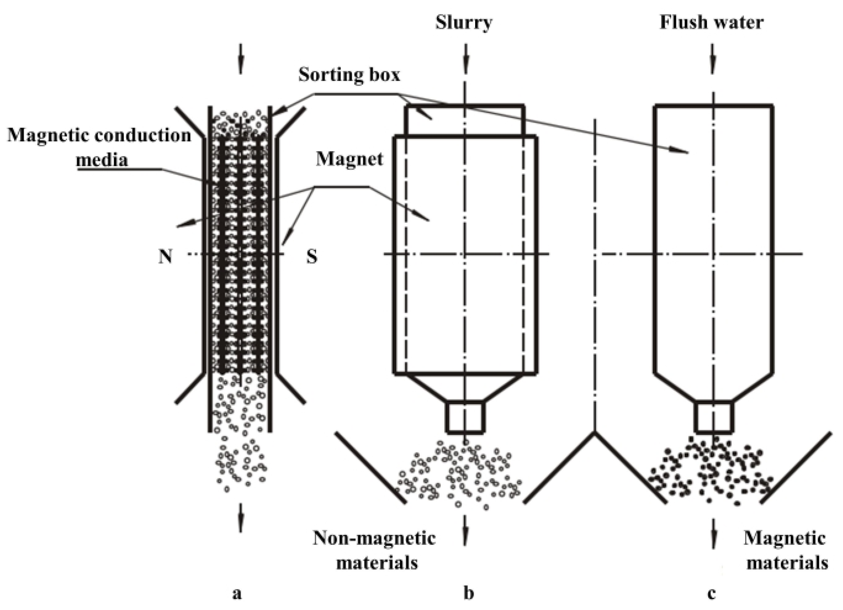
In 2004, Changsha Institute of Mining and Moscow Mining University developed the CRIMM double-box reciprocating permanent magnet high-gradient magnetic separator [26] to improve the overweight of the equipment, which consists of a removable magnetic conductive media heap and two parallel boxes. Only one of the boxes has a background magnetic field on the outside. When sorting, the slurry passes through the conductive medium under the action of gravity and fluid force, where magnetic particles adsorb onto the surface of the medium under the action of the magnetic field. Non-magnetic materials, such as feldspar, quartz, and kaolin, are not affected by the magnetic field and move into the non-magnetic product hopper (a and b in Figure 2). The feed is stopped when a sufficient quantity of magnetic particles is captured on the surface of the conductive medium, and the medium is pushed under the action of a pneumatic component into another chamber that is not covered by a background magnetic field. Magnetic and non-magnetic material separation is achieved by flushing the surface magnetic particles into the magnetic particle product hopper (c in Figure 2). The sorting principle of this device is shown in Figure 2. The magnetic system uses a rare earth permanent magnet large-cavity volume polar window frame magnet structure, where the strength of the uniform background magnetic field is above 0.8 T, the magnetic induction strength of the magnetic conduction medium surface is 1.3 T or more, and the magnetic field gradient exceeds 106 Gs/cm. The ore can be treated with different properties by using materials such as stainless steel rods, steel wool, steel plate mesh, and other conductive media. The advantages are low cost and energy consumption. The disadvantage is discontinuous operation, and with the adsorption of magnetic particles, the drastically reduced ability of the magnetic media to capture leads to poor performance.
Stronger background magnetic field strength is conducive to the purification and decomposition of ultra-fine non-metallic ore. Superconducting technology and pulsating high-gradient magnetic separation technology were used in kaolin purification and low-grade brass mine sorting for the first time by Xu J. Y. et al. [27]. Figure 3 shows the physical and structural diagram of the SLon-CD100 SPHGMS separator. This magnet needs to be cooled to 4 K to achieve a magnetic induction strength of 9.0 T. The energy consumption measured under this working condition is as low as 1.5 Kwh. This work used a superconducting SLon-CD100 SPHGMS sorter and a traditional pulsating high-gradient magnetic separator (SLon-100 PHGMS) for super-fine kaolin and brass mine purification. Plenty of experiments show that the purification capacity of the superconducting SLon-CD100 SPHGMS sorter is much higher than that of traditional equipment. When the magnetic field strength is 3.0 T, the iron removal rate could reach 39.52%. In low-iron products such as Fe2O3, the grade is 0.442%. In brass mine purification experiments, the SPHGMS sorter also performs well. At the maximum magnetic induction strength of 9.0 T, copper recovery is 90.74% and the concentrate grade is 3.19%, although the specification of superconducting magnetic separation for brass ore is not entirely superior to flotation [28]. However, it is environmentally friendly and has a large processing capacity. Thus, superconducting magnetic separation still has development potential.
2.2. Removing Impurities during the Metallurgical Process
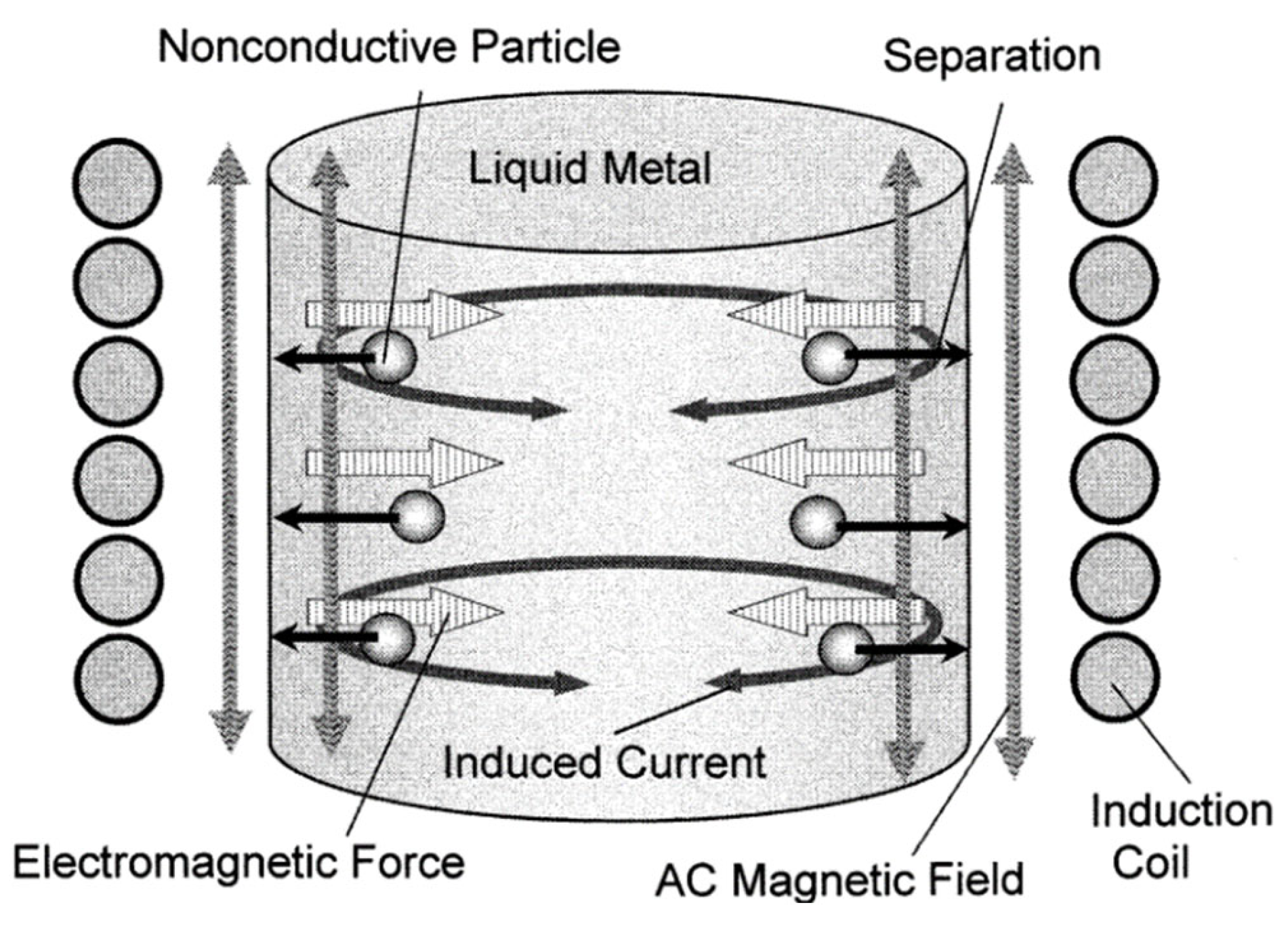
Although mineral processing processes have maximized the concentrate grade and reduced impurities, the purity of most materials, such as steel, copper, aluminum, metallurgical-grade silicon, and other non-metals, still does not meet the demand as researchers have very high requirements for the purity of their materials. Effective depth removal is the removal of small inclusions from the molten matter during the metallurgical process. Density differences between materials and impurities are largely ineffective when the particle size is small, making it difficult to efficiently remove very small solid particles using conventional methods such as settlement, filtration, or centrifugal separation. This can be avoided by using magnetic separation technology. Studies have shown that micrometer impurities can be removed under the action of electromagnetic fields [29,30]. As shown in Figure 4, the magnetic field is not in contact with the melt, so the safety coefficient is high [31] and the separation and removal operation can be achieved continuously [32,33,34]. Most importantly, the magnetic field can achieve stirring of the melt to improve the impurity removal rate. At present, based on electromagnetic separation technology proposed by Leenov [32] and Fautrelle [35], this is a quite an effective method. Electromagnetic forces can be created in the molten matter by applying an alternating current [36], an AC magnetic field [29,37,38], and by simultaneously applying an AC magnetic field [39,40].
Shu D. et al. [42] set up a laboratory-scale device for the continuous treatment of aluminum melts using a high-frequency alternating magnetic field. Although it has been reported that this magnetic field is used to separate impurities from alumina in non-continuous liquid metals up to 20 μm [43], there are few reports of continuous separation. The device works as shown in Figure 5, and the molten material consists of pure aluminum and Al5% Si-6% Al2O3 particles. The final alloy contains 3~4% Si, 1.5~2.5% Al2O3, and the rest is Al. The molten material flows through the runner through a separator wound by a seven-turn copper pipe, and power supply with IGBT induction heating generates 8.3 or 15.6 kHz of alternating current. The resulting magnetic field can repel inclusions in the separator from being captured on the wall [43]. Experimental results show that the maximum effective magnetic field strength is 0.175 T when the AC frequency is 8.3 kHz, the removal rate of 6 μm alumina inclusions was as high as 96.8%, and a changing magnetic field was found to facilitate efficient separation of the stirring melt.
3. Metal Recovery
Nowadays, modern technology brings convenience to life, and numerous advanced technology products are updated every day. This leads to more and more obsolete waste, such as cars, batteries, circuit boards, and so on. These huge quantities of waste not only burden waste disposal, but also cause incalculable harm to the environment [44]. At the same time, as mineable ore resources continue to deplete, recycling useful substances from waste is advantageous in terms of environmental protection and resource sustainability. Lithium batteries such as LiFePO4 (LFP) [45,46,47] are rich in iron and lithium [48], and recovery techniques including hydrometallurgy [49,50], mechanical chemistry [51], and electrochemistry [52] have been studied in the closed loop from LIB production to recycling and beyond as shown in Figure 6. When recovering Li and Fe from LFP, it is proposed to oxidize Fe2+ to Fe3O4 using Na2CO3 or NaOH, applying a magnetic field to separate it from the slag. The metal is recovered by baking and reduced to iron [53].
While recovering metal materials from silica-rich electronics (IC), Barnwal et al. [44] ground the pending ICs to 100~500 μm and applied a 1500 Gs (0.15 T) magnetic field to recover the black metal. Several experiments show that this method can obtain 120 g of black metal with 57.4% Fe and 26.0% Ni from 1 kg of discarded ICs.
4. Separation during the Chemical Process
Oil is the most important energy source involved in production and life [54]. Spills in the exploration, extraction, transport, and processing of petroleum are inevitable and a total of 5.87 million tons of crude oil leakage has been reported [55] in only 50 years, causing serious environmental hazards [56,57,58,59,60,61,62]. Traditional in situ incineration methods such as curing agents, chemical dispersion, and bioremediation remedies are difficult to deal with effectively and may pose other hazards to crude oil leaks [63,64], and the process is complex and expensive. The more efficient solution is to use special adsorption materials, using the surface hydrophobicity or characteristic structure of the material to combine with the oil. Examples include (MS/PDA/SiO2) made by Xie A. T. et al. [65], and the 3D network carbon nanotube aerogel prepared by Wu Z. Y. et al. [66]. However, most adsorption materials cannot be recycled efficiently, so adding magnetic material to the material and recovering it through the magnetic field is a simple, reliable, and recyclable strategy.
Renjith, P. K. et al. [67] added magnetic foam aerogel composites with ultra-paramagnetic properties to silica aerogel–melamine formaldehyde foam composites for petroleum adsorption (MFAC), which allows for the adsorption of oils and most organic solvents with its very large porosity, excellent oiliness, and hydrophobicity. Optical microscopy images of the oil-absorbed MFAC are depicted in Figure 7, which amply displays the oil retention capabilities of MFAC. As shown in Figure 8a,b, MFAC is significantly more hydrophobic, with a contact angle of 142°, compared to MF. In Figure 8c,d, EDX images confirm the presence of silica and magnetite particles in the composite. Magnetic nanoparticles inherent to the interior of the material can be used in addition to the background magnetic field to achieve recovery of the already adsorbed material, as shown in Figure 9.
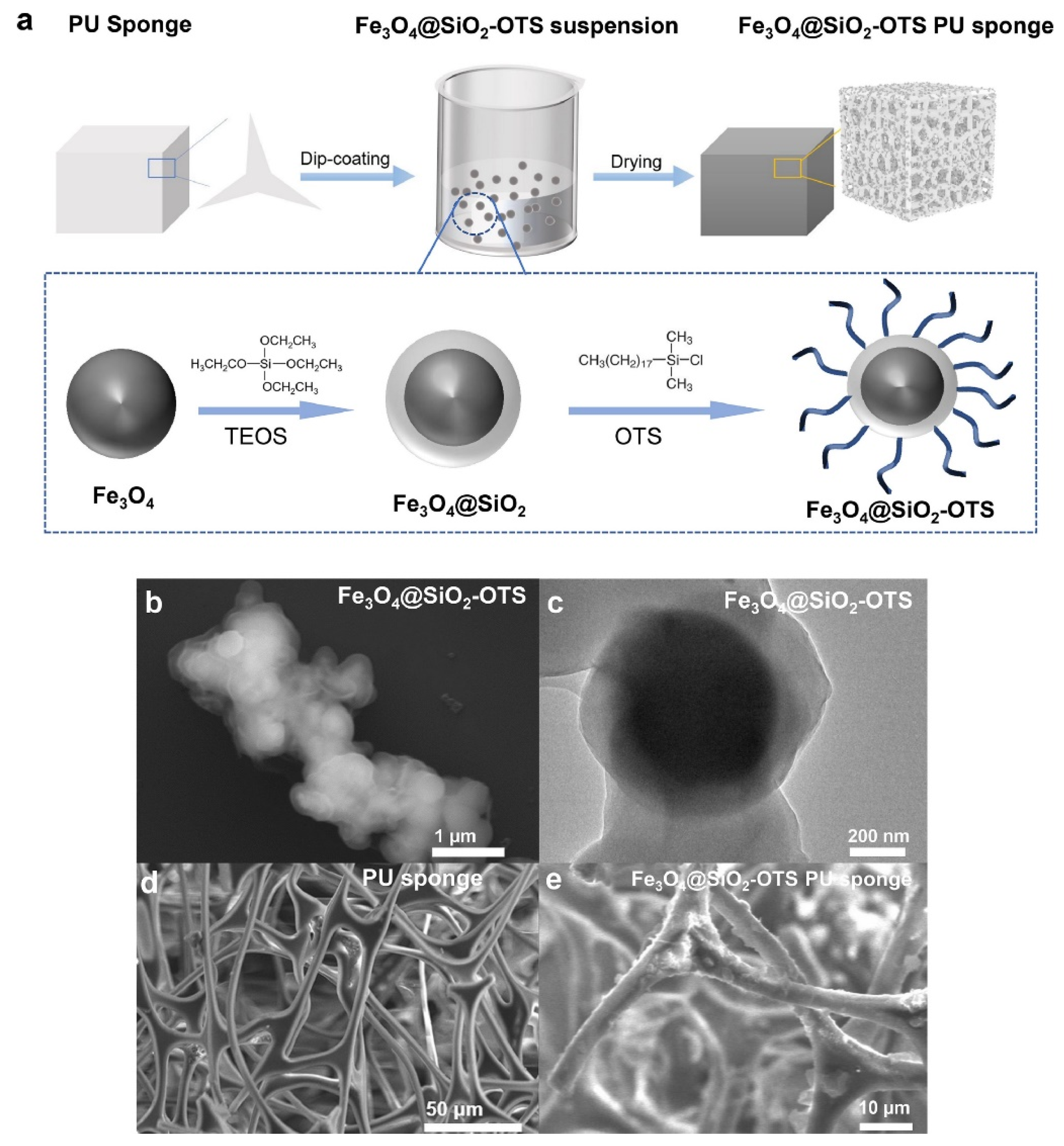
Wu S. Y. et al. [68] added magnetic Fe3O4 material to an ultra-hydrophobic polyurethane sponge (Octadecyl-trichloro-silane (OTS)) for oil–water separation and oil spill recovery. Synthetic Fe3O4@SiO2-OTS possesses super hydrophobic properties, as shown in Figure 10a. Figure 10b,c shows that magnetic Fe3O4 is encapsulated in a SiO2 shell with a thickness of 115~239 nm. OTS on the shell surface enables oil capture with hydrophobicity when adsorption occurs. The adsorption capacity is 48.6~62.3 g/g, as shown in Figure 10d,e. The SiO2 shell provides rich anchoring points for silanized functional groups and increases the stability of Fe3O4 nanoparticles. SEM images confirm the high uniformity and dispersion of Fe3O4@SiO2. It is recovered by applying an external magnetic field when adsorption is complete.
5. Magnetic Separation in Biomedical Targeting
It is often necessary to isolate or purify specific proteins, cells, or bacteria in research involving biology or pharmaceuticals. Traditional solutions often require complex pretreatment, such as the use of physical or chemical methods to cleave cells and the removal of cell fragments and contaminants by centrifugal or additive agents. These methods usually take a lot of time and may not work well [69]. With the development of markers and targeted selection, researchers have discovered an effective strategy for the separation of magnetic fields by specific adsorption of targeted proteins, cells, or bacteria using structures, drugs, and organic molecules that carry magnetic materials [70]. Xu C. J. et al. [71] made FePt and Co/Fe2O3 magnetic nanocrystals modified with nickel nitrogen triacetic acid (Ni-NTA), which can be used to orientate the adsorption of proteins with multi-histidine affinity labels and purify them using magnetic separation. The Au-Ni-Au nanorubes were prepared using anodized aluminium film for the separation of characterized proteins [72]. Lee I. S. et al. [73] used Ni/NiO nuclear shell-structure nanoparticles to selectively bind to the characterized protein using magnetic field separation. Deng Y. H. et al. [74] prepared a new type of sandwich structure with a mesoporous silica microsphere with a diameter of about 500 nm, as shown in Figure 11. This contains ultra-paramagnetic high magnetization (53.3 emu/g), and the magnetite core structure is coated with silica and a uniform mesopore (2.3 nm), as shown in Figure 12. As a highly effective adsorbent, large microcystic toxins can be removed quickly in liquid environments, and then the microsphere can be recycled and reused by magnetic separation technology [75,76]. Therefore, feature tagging and targeted adsorption co-magnetic field separation is a reliable way to capture and recycle micro-size objects such as proteins and cells.
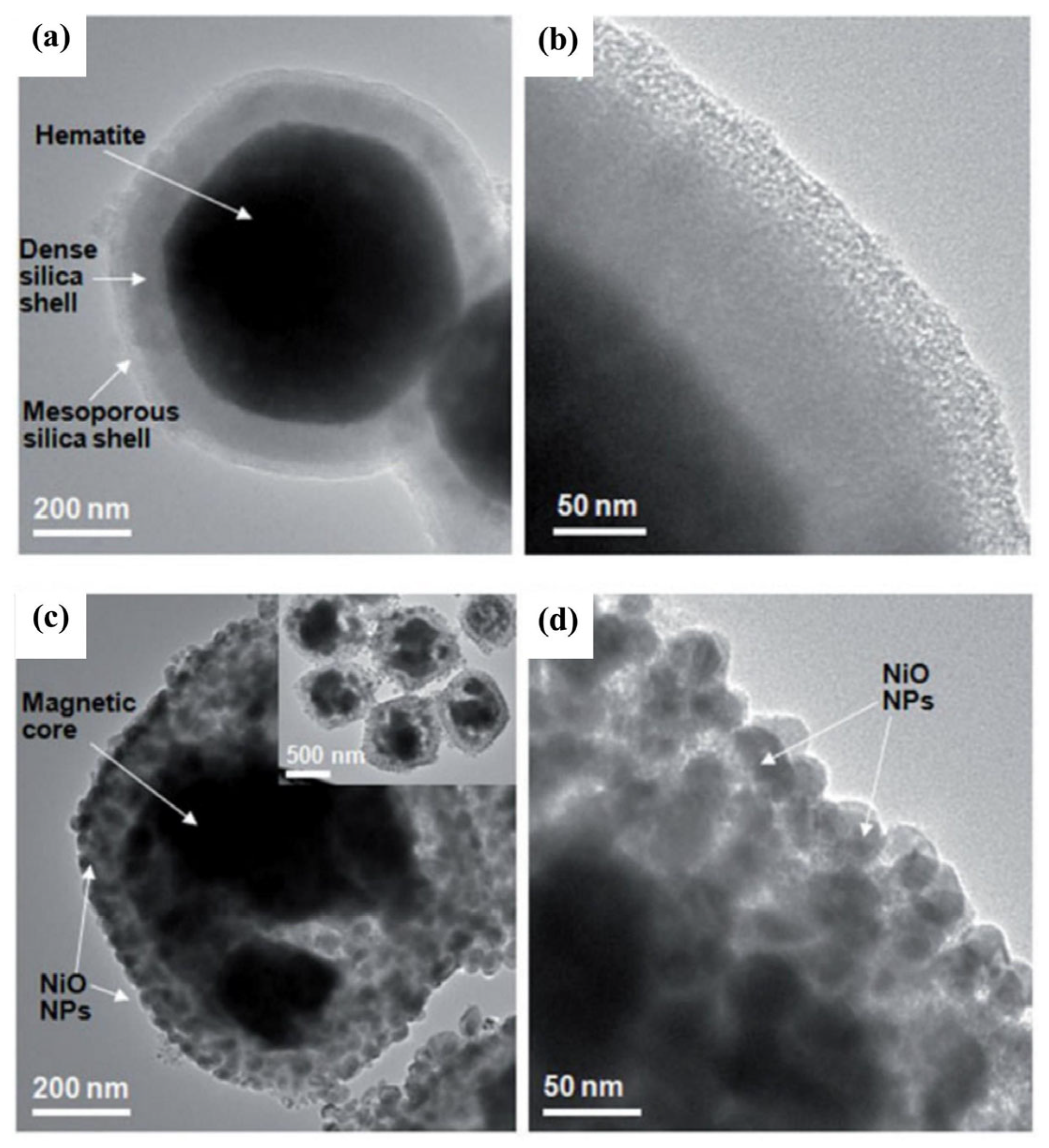
In fact, the researchers used magnetic fields to capture or separate the targeted individuals from structures, drugs, or organic molecules containing magnetic materials while expecting high reusability from these functional materials. This is because functional processes often take a lot of time and money, but some magnetic materials such as Ni/NiO shell structures have been utilized several times. As magnetic Ni is oxidized, the material’s magnetic properties are reduced. A magnetic nanocomposite, MNS-NiO, containing magnetite nanoparticles was synthesized [77] in order to enhance the magnetic properties of the material. The work begins by forming a layer of dense silica shell on the α-Fe2O3 surface by a sol-gel reaction. Then, micro-perforation is formed by series functionalization, as shown in Figure 13. Finally, hematite is reduced to magnetite in proportion to H2:N2 = 1:1 at 500 °C, and MNS-NiO-saturated magnetization with magnetic reinforcement can reach 82.1 emu/g. It can be used to target the adsorption of His-labeled proteins. After binding to the protein, the saturated magnetization strength is 79.1 emu/g. Magnetic separation technology can be used to achieve material recovery under magnetic field action [73,78,79], as shown in Figure 14.
6. Separation with Magnetic Species in Water and Wastewater Treatment
The use of water is indispensable for both production and life. With the increasing number of people, the risk of contamination of water resources is increasing. According to reports, around 30,000 people worldwide die every day from inadequate water supplies or poor water quality [80]. Thus, achieving efficient, low-cost water and wastewater purification is an important initiative for the benefit of humankind, especially in poor countries and regions where water is scarce.
Previously, a large number of nano-adsorption materials with high selectivity and high adsorption properties showed that they had great application prospects in wastewater treatment [81,82]. Magnetic materials demonstrate the advantages of low-cost and efficient recovery of magnetic fields in microbiology, sensing, and magnetic medicine applications [83,84,85]. Combining the excellent adsorption properties of nanomaterials with the reliability of magnetic materials, Agasti N. et al. [86] believe that magnetic nanomaterials with high saturation magnetization can be used as carriers of pollutants in water and wastewater, as shown in Figure 15. Purification of water and separation of contaminants by using a magnetic field are more efficient and may be less expensive than conventional methods such as precipitation.
Gao H.R. et al. [87] showed that graphene oxide (GO) has a large specific surface area which contains a large number of oxygen-containing functional groups that can be used for the treatment of heavy metals or organic pollutants in water. It also has the super magnetism of magnetite nanoparticles. Fe3O4/GO magnetic nanomaterials were synthesized for the treatment of dye wastewater. As shown in Figure 16a,b, the flaky structure is GO. The surface folds increase the adsorption capacity of heavy metals or organic pollutants. The dispersed white spherical particles on the fold are Fe3O4 nanoparticles with a particle size of 30~60 nm. Figure 16c shows Fe3O4/GO. The probability of adsorption decreases when the liquid can be dispersed sufficiently uniformly in the absence of an external magnetic field without settling too quickly, as shown in Figure 16d. Regarding Fe3O4/GO, the magnetic field can be fully captured after the magnetic field is applied to the outside, which shows that the composite material is recycled well and does not easily cause secondary contamination. Eventually, this work reported that Fe3O4/GO magnetic nanomaterials could be used to adsorb six dyes in dye wastewater. The most powerful removal was the removal of gentile purple, where the effective removal rate at 20 °C was 91.06% and adsorption was 34.35 mg/g.
7. Conclusions
Magnetic separation technology has the advantages of high efficiency, environmental protection, economy, and virtually no physical or chemical effect on treated substances. At present, the separation and purification process in some traditional chemical methods has been replaced by magnetic separation technology. This paper reviews the role of magnetic separation technology in different fields and its unique advantages, such as the use of magnetic separation technology to remove certain metals that can be magnetized in non-metals or the recovery of some valuable metals, which can be achieved while avoiding environmental pollution or the use of chemical agents which can change the chemical properties of materials. In the metallurgical process, this technology can be used to separate certain substances in the molten matter, in addition to achieving greater separation of fine particles when compared to traditional technology. The alternating magnetic field can also increase melt stirring to improve the sorting effect, reducing manual operation and improving safety. In addition, in chemical and biomedical applications, as well as in water and wastewater treatment, more and more functional materials carrying magnetic substances have been used and reported, thanks to magnetic separation technology recovery or precise control. The above cases demonstrate that magnetic separation technology has the advantages of relatively simple operation, large processing capacity, reusability, and low costs of resource utilization and environmental treatment. However, as mentioned, only a portion of minerals and substances can be treated with this technology as it has a small range of treatment objects, and the development of biomedical and water treatment in the field of markers targeting selection and other strategies is very useful. Thus, we believe that magnetic separation technology also has the potential and the need for continuous development.
Author Contributions
Writing-original draft preparation and funding acquisition, J.K.; investigation, K.W.; project administration Q.W.; writing-review and editing, Z.L. All authors have read and agreed to the published version of the manuscript.
Funding
This study was funded by the National Natural Science Foundation of China (No. 52174245), the Natural Science Foundation of Fujian Province (No. 2021J01640), the Open Foundation of the State Key Laboratory of Mineral Processing (No. BGRIMM-KJSKL-2022-03), and the Innovation and Entrepreneurship Training Program for College Students of Fujian Province (No. 202210386071).
Conflicts of Interest
Author Qian Wang is employed by Shandong Huate Magnet Technology Co., Ltd. The remaining authors declare that the research was conducted in the absence of any commercial or financial relationships that could be construed as a potential conflict of interest.
References
- Li, J.; Guo, Z.; Tang, H.; Li, J. Removal of Impurities from Metallurgical Grade Silicon by Liquation Refining Method. High Temp. Mater. Process. 2013, 32, 503–510. [Google Scholar] [CrossRef]
- Du, X.; Liang, C.; Hou, D.; Sun, Z.; Zheng, S. Scrubbing and Inhibiting Coagulation Effect on the Purification of Natural Powder Quartz. Minerals 2019, 9, 140. [Google Scholar] [CrossRef]
- Li, X.; Lv, X.; Xiang, L. Review of the State of Impurity Occurrences and Impurity Removal Technology in Phosphogypsum. Materials 2023, 16, 5630. [Google Scholar] [CrossRef] [PubMed]
- Qian, G.; Zhou, L.; Lu, J.; Pang, S.; Sun, Y.; Pang, J.; Wang, D.; Wei, K.; Ma, W.; Wang, Z. Toward Sustainability for Upcycling Sog-Si Scrap by an Immersion Rotational Segregation Purification Process. J. Clean. Prod. 2023, 416, 137978. [Google Scholar] [CrossRef]
- Jin, J.J.; Li, S.Q.; Zhao, X.; Guo, P.H.; Li, F. Study on Iron Removal by S-Hgms from Tungsten Tailings. Prog. Supercond. Cryog. 2020, 22, 17–20. [Google Scholar]
- John, M.; Choudhury, T.; Filimonov, R.; Kurvinen, E.; Saeed, M.; Mikkola, A.; Mänttäri, M.; Louhi-Kultanen, M. Impurity Separation Efficiency of Multi-Component Wastewater in a Pilot-Scale Freeze Crystallizer. Sep. Purif. Technol. 2020, 236, 116271. [Google Scholar] [CrossRef]
- Chi, Y.; Tian, C.; Li, H.; Zhao, Y. Polymerized Titanium Salts for Algae-Laden Surface Water Treatment and the Algae-Rich Sludge Recycle Toward Chromium and Phenol Degradation from Aqueous Solution. ACS Sustain. Chem. Eng. 2019, 7, 12964–12972. [Google Scholar] [CrossRef]
- Meng, L.; Wang, Z.; Wang, L.; Guo, L.; Guo, Z. Novel and Efficient Purification of Scrap Al-Mg Alloys Using Supergravity Technology. Waste Manag. 2021, 119, 22–29. [Google Scholar] [CrossRef] [PubMed]
- Wen, X.; Guo, L.; Bao, Q.; Guo, Z. Rapid Removal of Copper Impurity from Bismuth-Copper Alloy Melts Via Super-Gravity Separation. Int. J. Miner. Metall. Mater. 2021, 28, 1929–1939. [Google Scholar] [CrossRef]
- Nakhaei, F.; Irannajad, M. Reagents Types in Flotation of Iron Oxide Minerals: A Review. Miner. Process. Extr. Metall. Rev. 2018, 39, 89–124. [Google Scholar] [CrossRef]
- Jiang, X.; Chen, J.; Wei, M.; Li, F.; Ban, B.; Li, J. Effect of Impurity Content Difference Between Quartz Particles on Flotation Behavior and its Mechanism. Powder Technol. 2020, 375, 504–512. [Google Scholar] [CrossRef]
- Celik, M.S.; Pehlivanoglu, B.; Aslanbas, A.; Asmatulu, R. Flotation of Colored Impurities from Feldspar Ores. Min. Metall. Explor. 2001, 18, 101–105. [Google Scholar] [CrossRef]
- Kamali, S.; Sarraf-Mamoory, R.; Yourdkhani, A. A Novel Process for Extracting Bismuth from High Iron Content Copper Smelting Dust by Magnetic Separation and Leaching Process. Miner. Eng. 2024, 207, 108570. [Google Scholar] [CrossRef]
- Ku, J.G.; Lei, Z.Y.; Xia, J.; Guo, B.; Chen, H.H.; Peng, X.L.; Ran, H.X.; Deng, R.D. Dynamic Behavior and Separation Prediction of Magnetic Ore Bulks in Dry Medium-Intensity Magnetic Separator. Miner. Eng. 2021, 171, 107113. [Google Scholar] [CrossRef]
- Ku, J.G.; Lei, Z.Y.; Lin, H.; Yan, Q.X.; Chen, H.H.; Guo, B. Interaction of Magnetic Spheres in Magnetic Fields from the View of Magnetic Energy Density: A 3D Finite Element Analysis (Fea). Int. J. Min. Sci. Technol. 2022, 32, 1341–1350. [Google Scholar] [CrossRef]
- Mohanty, K.; Oliva, J.; Alfonso, P.; Sampaio, C.H.; Anticoi, H. A Comparative Study of Quartz and Potassium Feldspar Flotation Process Using Different Chemical Reagents. Minerals 2024, 14, 167. [Google Scholar] [CrossRef]
- Mathur, R.; Emproto, C.; Simon, A.C.; Godfrey, L.; Knaack, C.; Vervoort, J.D. A Chemical Separation and Measuring Technique for Titanium Isotopes for Titanium Ores and Iron-Rich Minerals. Minerals 2022, 12, 644. [Google Scholar] [CrossRef]
- Li, D.K.; Kou, J.; Sun, C.B.; Xing, Y.; Sun, J.F.; Jia, F.M.; Yu, B.Q.; Zhou, K.D. The Application of Superconducting Magnetic Separation in Copper-Moly Separation. Sep. Sci. Technol. 2019, 54, 1871–1878. [Google Scholar] [CrossRef]
- Chibowski, E.; Szczes, A. Magnetic Water Treatment a Review of the Latest Approaches. Chemosphere 2018, 203, 54–67. [Google Scholar] [CrossRef]
- Tang, J.; Wang, J.; Jia, H.; Wen, H.T.; Li, J.; Liu, W.B.; Li, J.Y. The Investigation on Fe3O4 Magnetic Flocculation for High Efficiency Treatment of Oily Micro-Polluted Water. J. Environ. Manag. 2019, 244, 399–407. [Google Scholar] [CrossRef]
- Li, J.S.; Li, X.X.; Shen, Q.; Zhang, Z.Z.; Du, F.H. Further Purification of Industrial Quartz by Much Milder Conditions and a Harmless Method. Environ. Sci. Technol. 2010, 44, 7673–7677. [Google Scholar] [CrossRef] [PubMed]
- Zegeye, A.; Yahaya, S.; Fialips, C.I.; White, M.L.; Gray, N.D.; Manning, D. Refinement of Industrial Kaolin by Microbial Removal of Iron-Bearing Impurities. Appl. Clay Sci. 2013, 86, 47–53. [Google Scholar] [CrossRef]
- Celik, M.S.; Can, I.; Eren, R.H. Removal of Titanium Impurities from Feldspar Ores by New Flotation Collectors. Miner. Eng. 1998, 11, 1201–1208. [Google Scholar] [CrossRef]
- Vegliò, F.; Passariello, B.; Abbruzzese, C. Iron Removal Process for High-Purity Silica Sands Production by Oxalic Acid Leaching. Ind. Eng. Chem. Res. 1999, 38, 4443–4448. [Google Scholar] [CrossRef]
- Chen, L.Z.; Zheng, Y.M.; Zeng, J.W.; Zheng, Y.X.; Liu, J. Magnetic Field Characteristics of Wet Belt Permanent High Gradient Magnetic Separator and its Full-Scale Purification for Garnet Ore. IEEE Trans. Magn. 2017, 53, 4900305. [Google Scholar] [CrossRef]
- Li, X.; Zhou, Y.; Cao, C.; Xu, Y.; Zhu, Y. Development of Crimm Double Canister Reciprocating Hg Permanent Magnetic Separator & its Application. Non-Met. Mines 2008, 31, 47–48. [Google Scholar]
- Xu, J.Y.; Xiong, D.H.; Song, S.X.; Chen, L.Z. Superconducting Pulsating High Gradient Magnetic Separation for Fine Weakly Magnetic Ores: Cases of Kaolin and Chalcopyrite. Results Phys. 2018, 10, 837–840. [Google Scholar] [CrossRef]
- Lizama, H.M. Processing of Chalcopyrite Ore by Heap Leaching and Flotation. Int. J. Miner. Process. 2017, 168, 55–67. [Google Scholar] [CrossRef]
- Elkaddah, N.; Patel, A.D.; Natarajan, T.T. The Electromagnetic Filtration of Molten Aluminum Using an Induced-Current Separator. JOM 1995, 47, 46–49. [Google Scholar] [CrossRef]
- Shu, D.; Li, T.X.; Sun, B.D.; Wang, J.; Zhou, Y.H. Study of Electromagnetic Separation of Nometallic Inclusions from Aluminum Melt. Metall. Mater. Trans. A 1999, 30, 2979–2988. [Google Scholar] [CrossRef]
- Asai, S. Development of Electromagnetic Processing of Materials. In Electromagnetic Processing of Materials: Materials Processing by Using Electric and Magnetic Functions; Asai, S., Ed.; Springer: Dordrecht, The Netherlands, 2012; pp. 1–7. [Google Scholar]
- Leenov, D.; Kolin, A. Theory of Electromagnetophoresis. I. Magnetohydrodynamic Forces Experienced by Spherical and Symmetrically Oriented Cylindrical Particles. J. Chem. Phys. 1954, 22, 683–688. [Google Scholar] [CrossRef]
- Zhang, L.F.; Wang, S.Q.; Dong, A.P.; Gao, J.W.; Damoah, L. Application of Electromagnetic (Em) Separation Technology to Metal Refining Processes: A Review. Metall. Mater. Trans. B-Process Metall. Mater. Process. Sci. 2014, 45, 2153–2185. [Google Scholar] [CrossRef]
- Toh, T.; Yamamura, H.; Kondo, H.; Wakoh, M.; Shimasak, S.; Taniguchi, S. Kinetics Evaluation of Inclusions Removal During Levitation Melting of Steel in Cold Crucible. ISIJ Int. 2007, 47, 1625–1632. [Google Scholar] [CrossRef]
- Fautrelle, Y. Metallurgical Applications of Magnetohydrodynamics; American Institute of Aeronautics and Astronautics: Reston, VA, USA, 1993; pp. 3–23. [Google Scholar]
- Taniguchi, S.; Brimacombe, J.K. Application of Pinch Force to the Separation of Inclusion Particles from Liquid Steel. ISIJ Int. 1994, 34, 722–731. [Google Scholar] [CrossRef]
- Chino, Y.; Iwai, K.; Asai, S. Propagation Characteristics of Surface Wave on Free Surface of a Molten Metal Induced by Imposition of Intermittent Alternating Magnetic Field. Tetsu Hagane-J. Iron Steel Inst. Jpn. 2001, 87, 579–584. [Google Scholar] [CrossRef]
- Shu, D.; Sun, B.; Li, K.; Wang, J.; Zhou, Y. Effects of Secondary Flow on the Electromagnetic Separation of Inclusions from Aluminum Melt in a Square Channel by a Solenoid. ISIJ Int. 2002, 42, 1241–1250. [Google Scholar] [CrossRef]
- Li, K.; Wang, J.; Shu, D.; Li, T.X.; Sun, B.D.; Zhou, Y.H. Theoretical and Experimental Investigation of Aluminum Melt Cleaning Using Alternating Electromagnetic Field. Mater. Lett. 2002, 56, 215–220. [Google Scholar] [CrossRef]
- Taniguchi, S.; Kikuchi, A. Removal of Nonmetallic Inclusion from Liquid Metal by Ac-Electromagnetic Force. In Proceedings of the 3rd International Symposium on Electromagnetic Processing of Materials, EPM2000, Nagoya, Japan, 1 January 2000. [Google Scholar]
- Takahashi, K.; Taniguchi, S. Electromagnetic Separation of Nonmetallic Inclusion from Liquid Metal by Imposition of High Frequency Magnetic Field. ISIJ Int. 2003, 43, 820–827. [Google Scholar] [CrossRef]
- Shu, D.; Sun, B.D.; Li, K.; Li, T.X.; Xu, Z.M.; Zhou, Y.H. Continuous Separation of Non-Metallic Inclusions from Aluminum Melt Using Alternating Magnetic Field. Mater. Lett. 2002, 55, 322–326. [Google Scholar] [CrossRef]
- Yamao, F.; Sassa, K.; Iwai, K.; Asai, S. Separation of Inclusions in Liquid Metal Using Fixed Alternating Magnetic Field. Tetsu Hagane-J. Iron Steel Inst. Jpn. 1997, 83, 30–35. [Google Scholar]
- Barnwal, A.; Dhawan, N. Physical Processing of Discarded Integrated Circuits for Recovery of Metallic Values. JOM 2020, 72, 2730–2738. [Google Scholar] [CrossRef]
- Fan, E.S.; Li, L.; Wang, Z.P.; Lin, J.; Huang, Y.X.; Yao, Y.; Chen, R.J.; Wu, F. Sustainable Recycling Technology for Li-Ion Batteries and Beyond: Challenges and Future Prospects. Chem. Rev. 2020, 120, 7020–7063. [Google Scholar] [CrossRef] [PubMed]
- Li, Z.; He, L.H.; Zhao, Z.W.; Wang, D.Z.; Xu, W.H. Recovery of Lithium and Manganese from Scrap Limn2O4 by Slurry Electrolysis. ACS Sustain. Chem. Eng. 2019, 7, 16738–16746. [Google Scholar] [CrossRef]
- Zhang, X.X.; Li, L.; Fan, E.S.; Xue, Q.; Bian, Y.F.; Wu, F.; Chen, R.J. Toward Sustainable and Systematic Recycling of Spent Rechargeable Batteries. Chem. Soc. Rev. 2018, 47, 7239–7302. [Google Scholar] [CrossRef] [PubMed]
- Chen, M.Y.; Ma, X.T.; Chen, B.; Arsenault, R.; Karlson, P.; Simon, N.; Wang, Y. Recycling End-of-Life Electric Vehicle Lithium-Ion Batteries. Joule 2019, 3, 2622–2646. [Google Scholar] [CrossRef]
- Li, L.; Fan, E.S.; Guan, Y.; Zhang, X.X.; Xue, Q.; Wei, L.; Wu, F.; Chen, R.J. Sustainable Recovery of Cathode Materials from Spent Lithium-Ion Batteries Using Lactic Acid Leaching System. ACS Sustain. Chem. Eng. 2017, 5, 5224–5233. [Google Scholar] [CrossRef]
- Li, X.L.; Zhang, J.; Song, D.W.; Song, J.S.; Zhang, L.Q. Direct Regeneration of Recycled Cathode Material Mixture from Scrapped Lifepo4 Batteries. J. Power Sources 2017, 345, 78–84. [Google Scholar] [CrossRef]
- Liu, K.; Tan, Q.Y.; Liu, L.L.; Li, J.H. Acid-Free and Selective Extraction of Lithium from Spent Lithium Iron Phosphate Batteries Via a Mechanochemically Induced Isomorphic Substitution. Environ. Sci. Technol. 2019, 53, 9781–9788. [Google Scholar] [CrossRef] [PubMed]
- Yu, J.Z.; Wang, X.; Zhou, M.Y.; Wang, Q. A Redox Targeting-Based Material Recycling Strategy for Spent Lithium Ion Batteries. Energy Environ. Sci. 2019, 12, 2672–2677. [Google Scholar] [CrossRef]
- Zhang, B.; Qu, X.; Chen, X.; Liu, D.; Zhao, Z.; Xie, H.; Wang, D.; Yin, H. A Sodium Salt-Assisted Roasting Approach Followed by Leaching for Recovering Spent Lifepo4 Batteries. J. Hazard. Mater. 2022, 424, 127586. [Google Scholar] [CrossRef]
- Yüksel, S.; Dinçer, H.; Meral, Y. Financial Analysis of International Energy Trade: A Strategic Outlook for Eu-15. Energies 2019, 12, 431. [Google Scholar] [CrossRef]
- Chen, J.H.; Zhang, W.P.; Li, S.F.; Zhang, F.W.; Zhu, Y.H.; Huang, X.L. Identifying Critical Factors of Oil Spill in the Tanker Shipping Industry Worldwide. J. Clean. Prod. 2018, 180, 1–10. [Google Scholar] [CrossRef]
- Barron, M.G.; Vivian, D.N.; Heintz, R.A.; Yim, U.H. Long-Term Ecological Impacts from Oil Spills: Comparison of Exxon Valdez, Hebei Spirit, and Deepwater Horizon. Environ. Sci. Technol. 2020, 54, 6456–6467. [Google Scholar] [CrossRef] [PubMed]
- Lewis, J.P.; Tarnecki, J.H.; Garner, S.B.; Chagaris, D.D.; Patterson, W.F. Changes in Reef Fish Community Structure Following the Deepwater Horizon Oil Spill. Sci. Rep. 2020, 10, 5621. [Google Scholar] [CrossRef] [PubMed]
- Gao, H.; Wu, M.L.; Liu, H.; Xu, Y.R.; Liu, Z.L. Effect of Petroleum Hydrocarbon Pollution Levels on the Soil Microecosystem and Ecological Function. Environ. Pollut. 2022, 293, 118511. [Google Scholar] [CrossRef]
- Baker, M.C.; Steinhoff, M.A.; Fricano, G.F. Integrated Effects of the Deepwater Horizon Oil Spill on Nearshore Ecosystems. Mar. Ecol. Prog. Ser. 2017, 576, 219–234. [Google Scholar] [CrossRef]
- Wallace, B.P.; Brosnan, T.; McLamb, D.; Rowles, T.; Ruder, E.; Schroeder, B.; Schwacke, L.; Stacy, B.; Sullivan, L.; Takeshita, R.; et al. Effects of the Deepwater Horizon Oil Spill on Protected Marine Species. Endanger. Species Res. 2017, 33, 1–7. [Google Scholar] [CrossRef]
- Jiang, Z.; Huang, Y.; Xu, X.; Liao, Y.; Shou, L.; Liu, J.; Chen, Q.; Zeng, J. Advance in the Toxic Effects of Petroleum Water Accommodated Fraction on Marine Plankton. Acta Ecol. Sin. 2010, 30, 8–15. [Google Scholar] [CrossRef]
- Laffon, B.; Pásaro, E.; Valdiglesias, V. Effects of Exposure to Oil Spills on Human Health: Updated Review. J. Toxicol. Environ. Health Part B 2016, 19, 105–128. [Google Scholar] [CrossRef]
- Faksness, L.; Altin, D.; Dolva, H.; Nordtug, T. Chemical and Toxicological Characterisation of Residues from Offshore in-Situ Burning of Spilled Fuel Oils. Toxicol. Rep. 2022, 9, 163–170. [Google Scholar] [CrossRef]
- Delaune, R.D.; Lindau, C.W.; Jugsujinda, A. Effectiveness of “Nochar” Solidifier Polymer in Removing Oil from Open Water in Coastal Wetlands. Spill Sci. Technol. Bull. 1999, 5, 357–359. [Google Scholar] [CrossRef]
- Xie, A.T.; Chen, Y.Y.; Cui, J.Y.; Lang, J.H.; Li, C.X.; Yan, Y.S.; Dai, J.D. Facile and Green Fabrication of Superhydrophobic Sponge for Continuous Oil/Water Separation from Harsh Environments. Colloids Surf. A-Physicochem. Eng. Asp. 2019, 563, 120–129. [Google Scholar] [CrossRef]
- Wu, Z.Y.; Li, C.; Liang, H.W.; Zhang, Y.N.; Wang, X.; Chen, J.F.; Yu, S.H. Carbon Nanofiber Aerogels for Emergent Cleanup of Oil Spillage and Chemical Leakage Under Harsh Conditions. Sci. Rep. 2014, 4, 4079. [Google Scholar] [CrossRef] [PubMed]
- Renjith, P.K.; Sarathchandran, C.; Chandramohanakumar, N.; Sekkar, V. Silica Aerogel Composite with Inherent Superparamagnetic Property: A Pragmatic and Ecofriendly Approach for Oil Spill Clean-Up Under Harsh Conditions. Mater. Today Sustain. 2023, 24, 100498. [Google Scholar] [CrossRef]
- Wu, S.Y.; Xiang, Y.J.; Cai, Y.Q.; Liu, J.F. Superhydrophobic Magnetic Fe3O4 Polyurethane Sponges for Oil-Water Separation and Oil-Spill Recovery. J. Environ. Sci. 2024, 139, 160–169. [Google Scholar] [CrossRef] [PubMed]
- Greenstein, D.; Brent, R. Introduction to vectors derived from filamentous phages. In Current Protocols in Molecular Biology; Unit 1–Unit 14; John Wiley & Sons, Inc.: Boston, MA, USA, 2001; Chapter 1. [Google Scholar]
- Leuschner, C.; Kumar, C.S.S.R. Nanoparticles for Cancer Drug Delivery. In Nanofabrication towards Biomedical Applications; Wiley: Weinheim, Germany, 2005; pp. 289–326. [Google Scholar]
- Xu, C.J.; Xu, K.M.; Gu, H.W.; Zhong, X.F.; Guo, Z.H.; Zheng, R.K.; Zhang, X.X.; Xu, B. Nitrilotriacetic Acid-Modified Magnetic Nanoparticles as a General Agent to Bind Histidine-Tagged Proteins. J. Am. Chem. Soc. 2004, 126, 3392–3393. [Google Scholar] [CrossRef] [PubMed]
- Lee, K.B.; Park, S.; Mirkin, C.A. Multicomponent Magnetic Nanorods for Biomolecular Separations. Angew. Chem.-Int. Ed. 2004, 43, 3048–3050. [Google Scholar] [CrossRef] [PubMed]
- Lee, I.S.; Lee, N.; Park, J.; Kim, B.H.; Yi, Y.W.; Kim, T.; Kim, T.K.; Lee, I.H.; Paik, S.R.; Hyeon, T. Ni/Nio Core/Shell Nanoparticles for Selective Binding and Magnetic Separation of Histidine-Tagged Proteins. J. Am. Chem. Soc. 2006, 128, 10658–10659. [Google Scholar] [CrossRef] [PubMed]
- Deng, Y.H.; Qi, D.W.; Deng, C.H.; Zhang, X.M.; Zhao, D.Y. Superparamagnetic High-Magnetization Microspheres with an Fe3O4@Sio2 Core and Perpendicularly Aligned Mesoporous Sio2 Shell for Removal of Microcystins. J. Am. Chem. Soc. 2008, 130, 28. [Google Scholar] [CrossRef]
- Ma, Z.Y.; Liu, H.Z. Synthesis and Surface Modification of Magnetic Particles for Application in Biotechnology and Biomedicine. China Particuol. 2007, 5, 1–10. [Google Scholar] [CrossRef]
- Xu, X.; Deng, C.; Gao, M.; Yu, W.; Yang, P.; Zhang, X. Synthesis of Magnetic Microspheres with Immobilized Metal Ions for Enrichment and Direct Determination of Phosphopeptides by Matrix-Assisted Laser Desorption Ionization Mass Spectrometry. Adv. Mater. 2006, 18, 3289–3293. [Google Scholar] [CrossRef]
- Kim, J.; Piao, Y.; Lee, N.; Park, Y.I.; Lee, I.H.; Lee, J.H.; Paik, S.R.; Hyeon, T. Magnetic Nanocomposite Spheres Decorated with Nio Nanoparticles for a Magnetically Recyclable Protein Separation System. Adv. Mater. 2010, 22, 57. [Google Scholar] [CrossRef] [PubMed]
- Park, J.; Kang, E.; Son, S.U.; Park, H.M.; Lee, M.K.; Kim, J.; Kim, K.W.; Noh, H.J.; Park, J.H.; Bae, C.J.; et al. Monodisperse Nanoparticles of Ni and Nio: Synthesis, Characterization, Self-Assembled Superlattices, and Catalytic Applications in the Suzuki Coupling Reaction. Adv. Mater. 2005, 17, 429–434. [Google Scholar] [CrossRef]
- Deng, Y.; Deng, C.; Qi, D.; Liu, C.; Liu, J.; Zhang, X.; Zhao, D. Synthesis of Core/Shell Colloidal Magnetic Zeolite Microspheres for the Immobilization of Trypsin. Adv. Mater. 2009, 21, 1377–1382. [Google Scholar] [CrossRef]
- Ochieng, G.M.; Seanego, E.S.; Nkwonta, O.I. Impacts of Mining on Water Resources in South Africa: A Review. Sci. Res. Essays 2010, 5, 3351–3357. [Google Scholar]
- Dehghani, M.H.; Ahmadi, S.; Ghosh, S.; Othmani, A.; Osagie, C.; Meskini, M.; AlKafaas, S.S.; Malloum, A.; Khanday, W.A.; Jacob, A.O.; et al. Recent Advances on Sustainable Adsorbents for the Remediation of Noxious Pollutants from Water and Wastewater: A Critical Review. Arab. J. Chem. 2023, 16, 105303. [Google Scholar] [CrossRef]
- Allahkarami, E.; Monfared, A.D.; Silva, L.; Dotto, G.L. Lead Ferrite-Activated Carbon Magnetic Composite for Efficient Removal of Phenol from Aqueous Solutions: Synthesis, Characterization, and Adsorption Studies. Sci. Rep. 2022, 12, 10718. [Google Scholar] [CrossRef] [PubMed]
- Koksharov, Y.A.; Gubin, S.P.; Taranov, I.; Khomutov, G.B.; Gulyaev, Y. Magnetic Nanoparticles in Medicine: Progress, Problems, and Advances. J. Commun. Technol. Electron. 2022, 67, 101–116. [Google Scholar] [CrossRef]
- Kubelick, K.P.; Mehrmohammadi, M. Magnetic Particles in Motion: Magneto-Motive Imaging and Sensing. Theranostics 2022, 12, 1783–1799. [Google Scholar] [CrossRef]
- Nakhlband, A.; Kholafazad-Kordasht, H.; Rahimi, M.; Mokhtarzadeh, A.; Soleymani, J. Applications of Magnetic Materials in the Fabrication of Microfluidic-Based Sensing Systems: Recent Advances. Microchem. J. 2022, 173, 107042. [Google Scholar] [CrossRef]
- Agasti, N.; Gautam, V.; Priyanka; Manju; Pandey, N.; Genwa, M.; Meena, P.L.; Tandon, S.; Samantaray, R. Carbon Nanotube Based Magnetic Composites for Decontamination of Organic Chemical Pollutants in Water: A Review. Appl. Surf. Sci. Adv. 2022, 10, 100270. [Google Scholar] [CrossRef]
- Gao, H.R.; Li, W.T.; Duan, S.Y.; Jin, S.L.; Xiong, C.X. Synthesis of Fe3O4/Go Magnetic Nanomaterials and their Adsorption of Gentian Violet Dye. New Chem. Mater. 2023, 51, 295–300. [Google Scholar]
Figure 1.
WBHGMS captures magnetic material in inclined slurry. Fm—magnetic force. Fg—gravity. Ff—buoyant force. F0—friction force. Fd—hydrodynamic resistance [25].
Figure 1.
WBHGMS captures magnetic material in inclined slurry. Fm—magnetic force. Fg—gravity. Ff—buoyant force. F0—friction force. Fd—hydrodynamic resistance [25].

Figure 2.
Principle of sorting CRIMM double-box reciprocating permanent magnet high-gradient magnetic separator [26].
Figure 2.
Principle of sorting CRIMM double-box reciprocating permanent magnet high-gradient magnetic separator [26].

Figure 3.
SLon-CD100 SPHGMS separator’s physical and structural diagrams. 1—feed box; 2—nylon sleeves; 3—vacuum insulating valve; 4—cryostat; 5—superconducting magnet; 6—magnetic matrix; 7—vacuum chamber; 8—pulsating mechanism; 9—product box; 10—valve; 11—cryocooler [27].
Figure 3.
SLon-CD100 SPHGMS separator’s physical and structural diagrams. 1—feed box; 2—nylon sleeves; 3—vacuum insulating valve; 4—cryostat; 5—superconducting magnet; 6—magnetic matrix; 7—vacuum chamber; 8—pulsating mechanism; 9—product box; 10—valve; 11—cryocooler [27].

Figure 4.
Electromagnetic separation of nonconductive particles from a cylindrical liquid metal in an induction furnace [41].
Figure 4.
Electromagnetic separation of nonconductive particles from a cylindrical liquid metal in an induction furnace [41].

Figure 5.
Continuous electromagnetic separation of molten metal [42].
Figure 5.
Continuous electromagnetic separation of molten metal [42].

Figure 6.
Closed loop from production to recycling of LIBs and beyond [52].
Figure 6.
Closed loop from production to recycling of LIBs and beyond [52].

Figure 7.
(a) MFAC composite; (b) oiled MFAC with engine oil; (c) oiled MFAC with light oil [67].
Figure 7.
(a) MFAC composite; (b) oiled MFAC with engine oil; (c) oiled MFAC with light oil [67].

Figure 8.
SEM images of (a) neat MF; (b) MFAC composite; energy-dispersive X-ray spectra (EDX) of MF (c); and MFAC composite (d) [67].
Figure 8.
SEM images of (a) neat MF; (b) MFAC composite; energy-dispersive X-ray spectra (EDX) of MF (c); and MFAC composite (d) [67].

Figure 9.
Material adsorption, magnetic field recovery process: (a) adsorbed oil; (b) process of material adsorption; (c,d) recovery of materials using magnetic fields [67].
Figure 9.
Material adsorption, magnetic field recovery process: (a) adsorbed oil; (b) process of material adsorption; (c,d) recovery of materials using magnetic fields [67].

Figure 10.
(a) Schematic of the preparation of the Fe3O4@SiO2-OTS PU sponge; (b) Scanning electron microscopy (SEM) image of Fe3O4@SiO2-OTS; (c) High-resolution transmission electron microscopy (HRTEM) images of Fe3O4@SiO2-OTS; (d) SEM image of the bare PU sponge; (e) SEM image of the Fe3O4@SiO2-OTS PU sponge [68].

Figure 11.
The Formation of Fe3O4@nSiO2@mSiO2 Microspheres [74].
Figure 11.
The Formation of Fe3O4@nSiO2@mSiO2 Microspheres [74].

Figure 12.
TEM images of (a) Fe3O4 particles; (b) Fe3O4@nSiO2; (c–e) Fe3O4@nSiO2@mSiO2 microspheres; (f) SEM image of Fe3O4@nSiO2@mSiO2 microspheres [74].
Figure 12.
TEM images of (a) Fe3O4 particles; (b) Fe3O4@nSiO2; (c–e) Fe3O4@nSiO2@mSiO2 microspheres; (f) SEM image of Fe3O4@nSiO2@mSiO2 microspheres [74].

Figure 13.
TEM images of mesoporous silica-coated hematite particles (a,b) and MNS-NiO (c,d) [77].
Figure 13.
TEM images of mesoporous silica-coated hematite particles (a,b) and MNS-NiO (c,d) [77].

Figure 14.
Magnetic MNS-NiO-targeted adsorption protein and magnetic separation process [77].
Figure 14.
Magnetic MNS-NiO-targeted adsorption protein and magnetic separation process [77].

Figure 15.
Magnetic nanomaterials with high saturation magnetization [86].
Figure 15.
Magnetic nanomaterials with high saturation magnetization [86].

Figure 16.
(a,b) the SEM image of Fe3O4/GO; (c,d) magnetic separation performance test of Fe3O4/GO [87].
Figure 16.
(a,b) the SEM image of Fe3O4/GO; (c,d) magnetic separation performance test of Fe3O4/GO [87].

Disclaimer/Publisher’s Note: The statements, opinions and data contained in all publications are solely those of the individual author(s) and contributor(s) and not of MDPI and/or the editor(s). MDPI and/or the editor(s) disclaim responsibility for any injury to people or property resulting from any ideas, methods, instructions or products referred to in the content. |
© 2024 by the authors. Licensee MDPI, Basel, Switzerland. This article is an open access article distributed under the terms and conditions of the Creative Commons Attribution (CC BY) license (https://creativecommons.org/licenses/by/4.0/).
Share and Cite
MDPI and ACS Style
Ku, J.; Wang, K.; Wang, Q.; Lei, Z. Application of Magnetic Separation Technology in Resource Utilization and Environmental Treatment. Separations 2024, 11, 130. https://doi.org/10.3390/separations11050130
AMA Style
Ku J, Wang K, Wang Q, Lei Z. Application of Magnetic Separation Technology in Resource Utilization and Environmental Treatment. Separations. 2024; 11(5):130. https://doi.org/10.3390/separations11050130
Chicago/Turabian StyleKu, Jiangang, Kunpeng Wang, Qian Wang, and Zhongyun Lei. 2024. "Application of Magnetic Separation Technology in Resource Utilization and Environmental Treatment" Separations 11, no. 5: 130. https://doi.org/10.3390/separations11050130
Note that from the first issue of 2016, this journal uses article numbers instead of page numbers. See further details here.