The Analysis of Nonlinear Vibrations of Top-Tensioned Cantilever Pipes Conveying Pressurized Steady Two-Phase Flow under Thermal Loading

Abstract
:1. Introduction
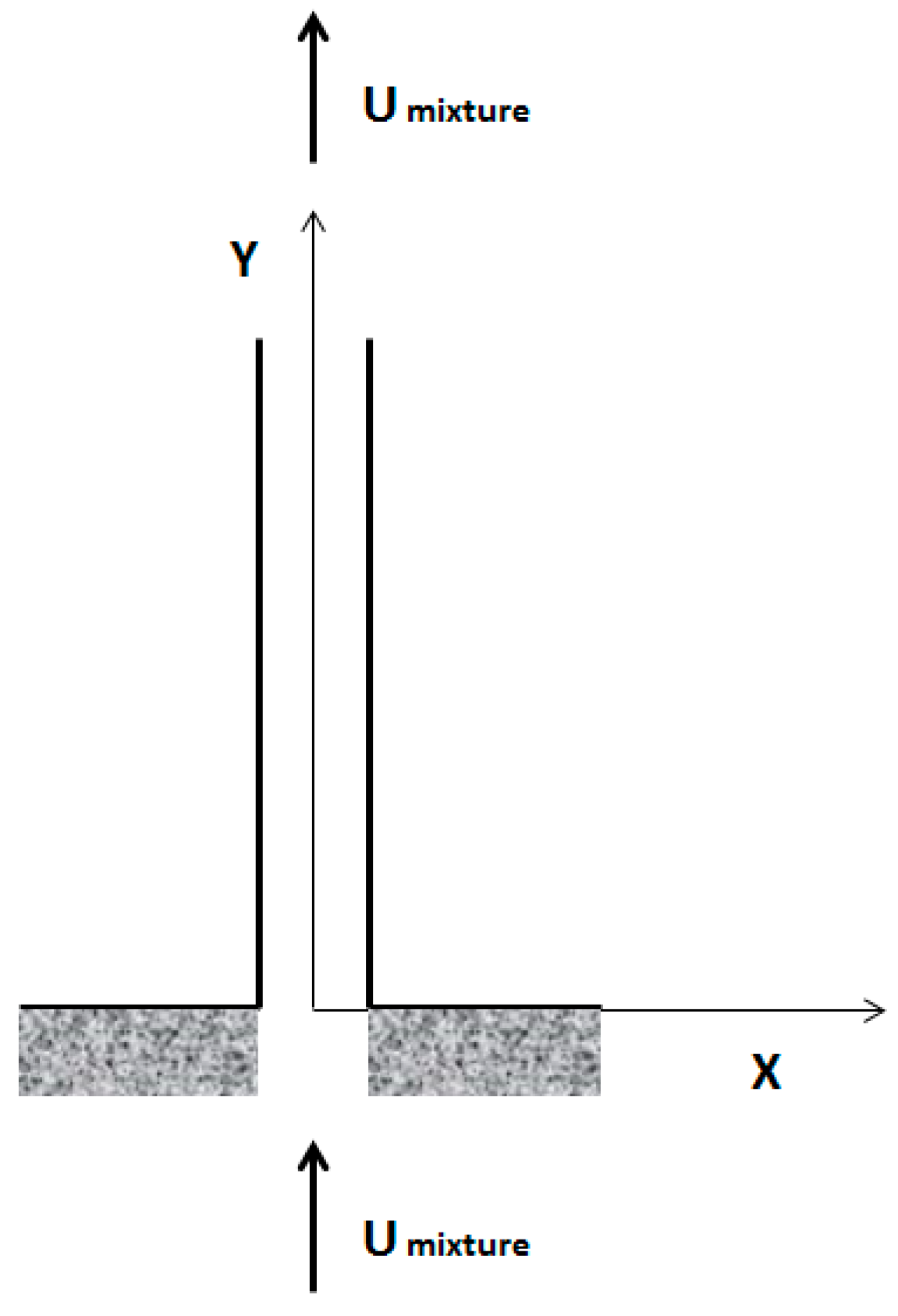
2. Problem Formulation and Modelling
2.1. Derivation of the Equation of Motion
- is the mass of the phases in the fluid;
- is the flow velocity of the phases in the fluid; and
- is the Lagrangian operator expressed in Equation (2):
2.1.1. Kinetic Energy
2.1.2. Potential Energy
2.1.3. Non-Conservative Work Done
2.2. Equation of Motion for Multiphase Flow
Dimensionless Equation of Motion for Two-Phase Flow
2.3. Empirical Gas–Liquid Two-Phase Flow Model
3. Method of Solution
3.1. Linear Analysis
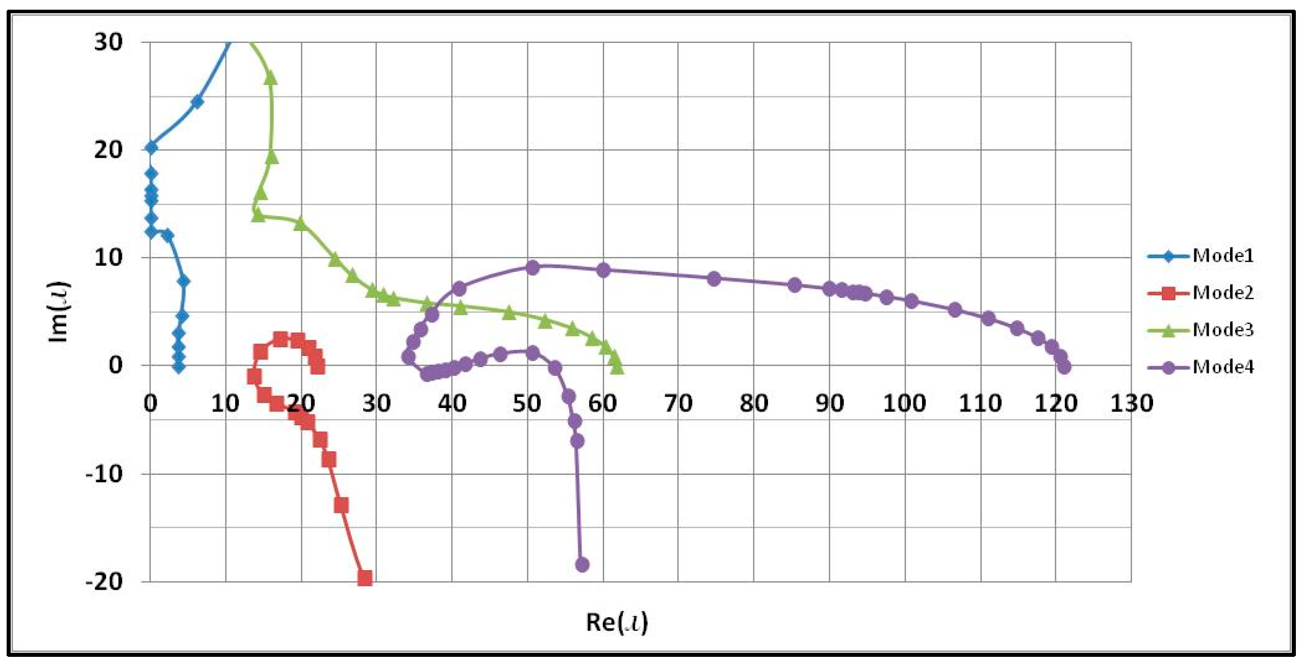
3.1.1. Natural Frequencies and Modal Functions
3.1.2. Solution to Axial Vibration Problem
3.1.3. Solution to Transverse Vibration Problem
3.2. Nonlinear Analysis
3.2.1. Nonlinear Axial and Transverse Vibration Problem
3.2.2. When Is Far from
3.2.3. When Is Close to
4. Numerical Results
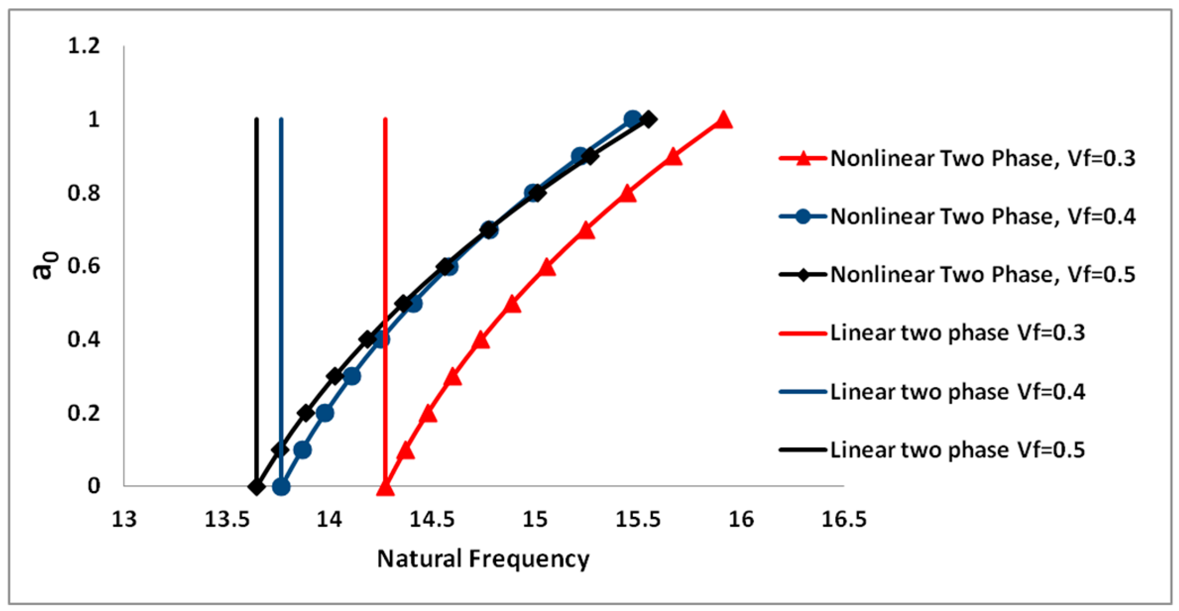
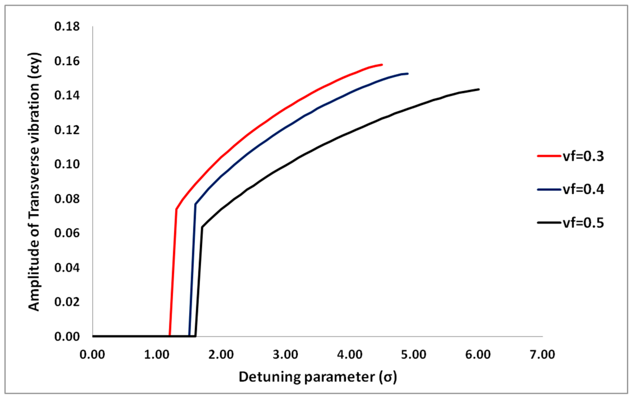
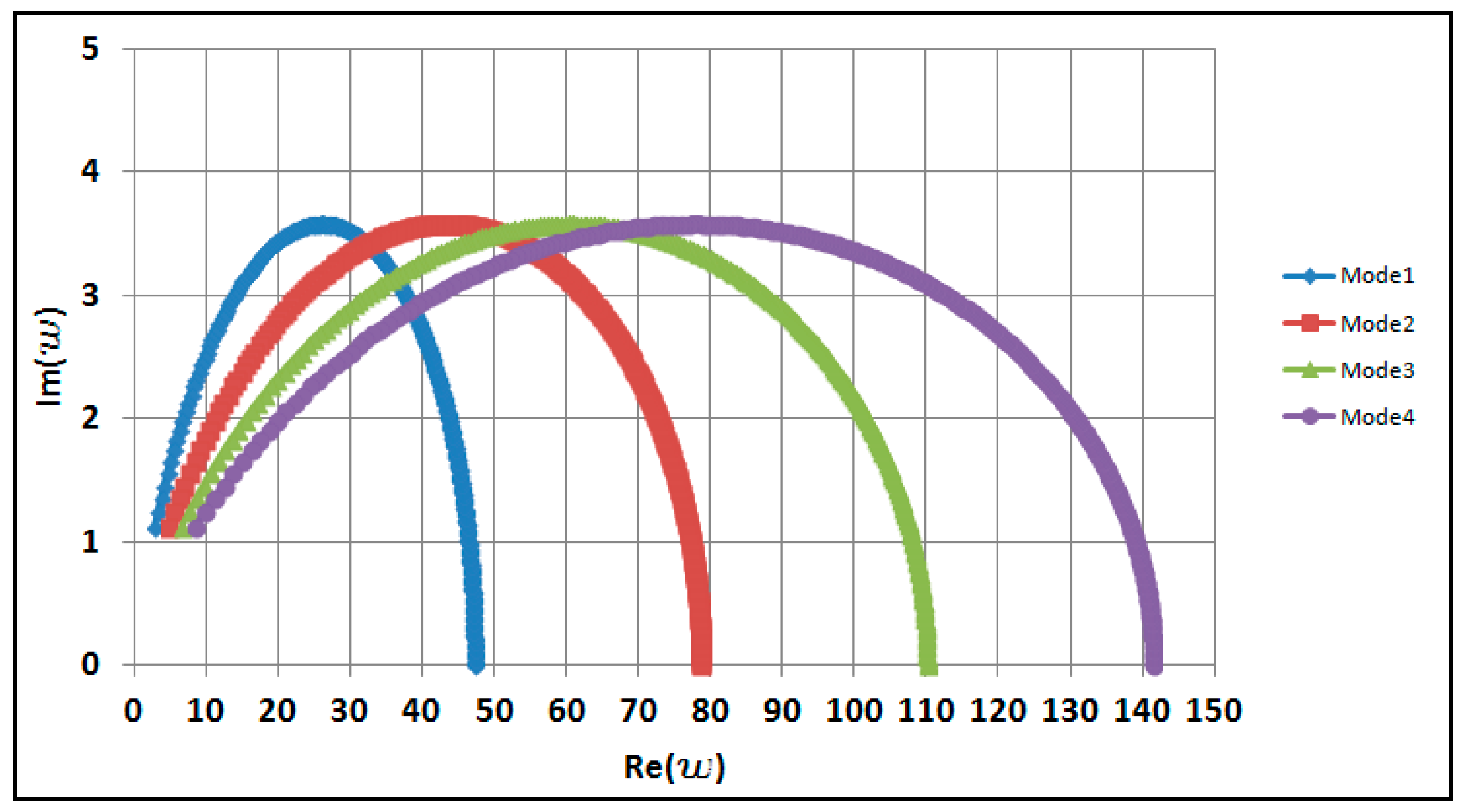
4.1. Effects of Two-Phase Flow on the Dynamic Behavior of the Pipe
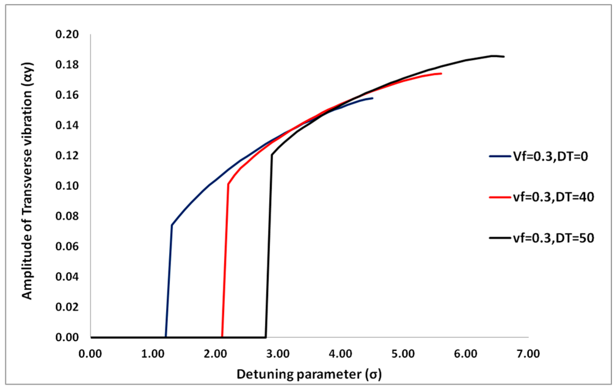
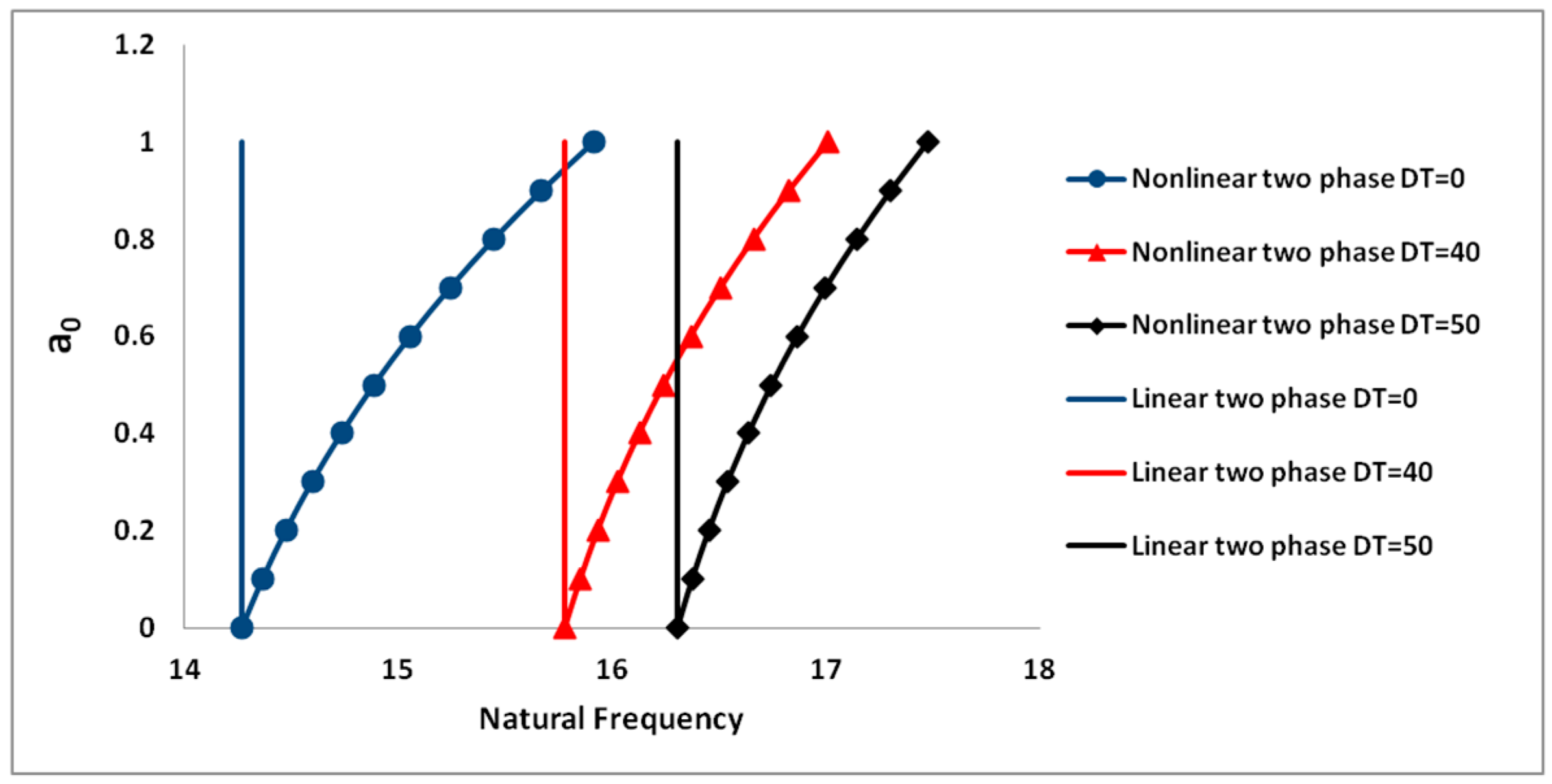
4.1.1. Effects of Temperature Difference on the Dynamic Behavior
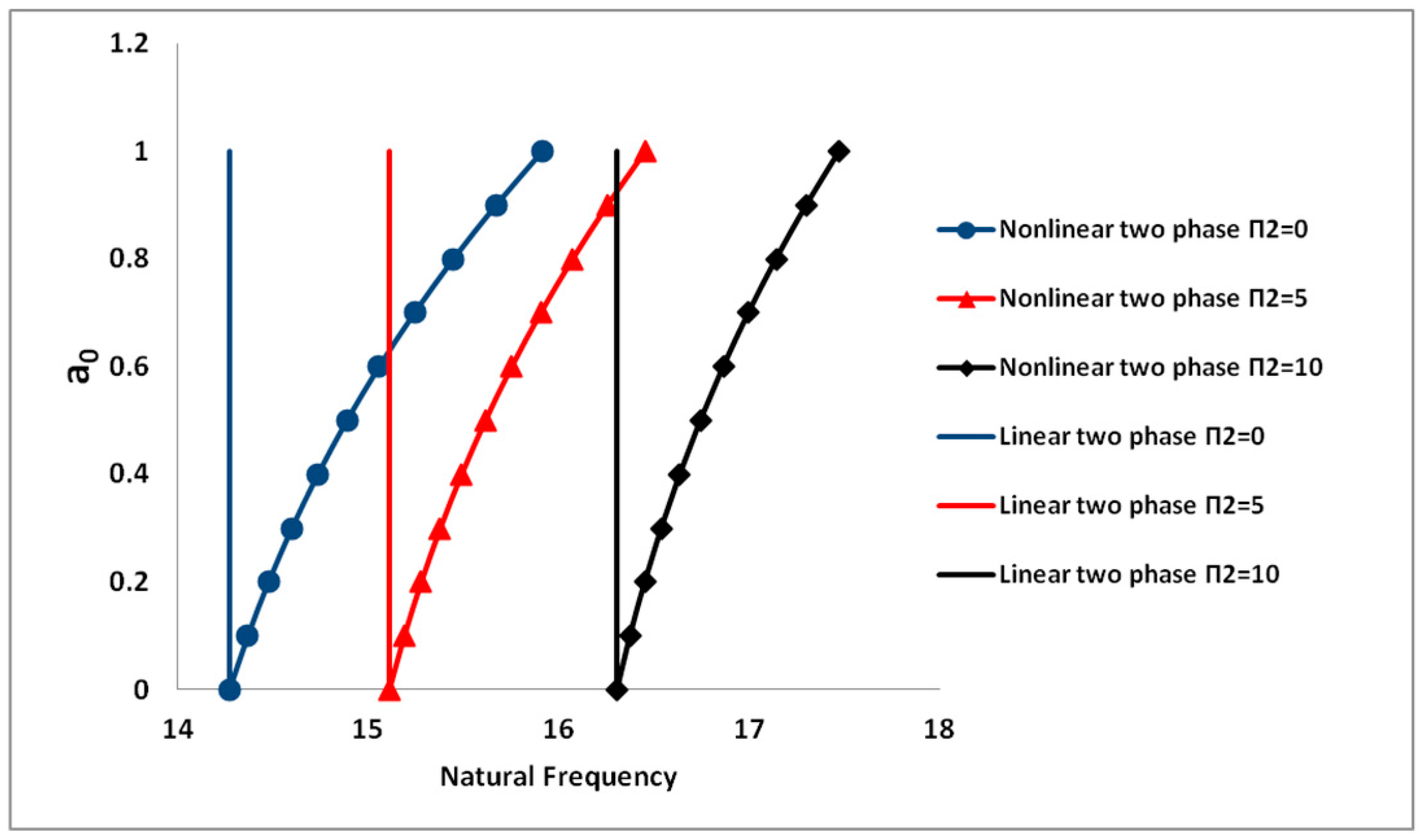
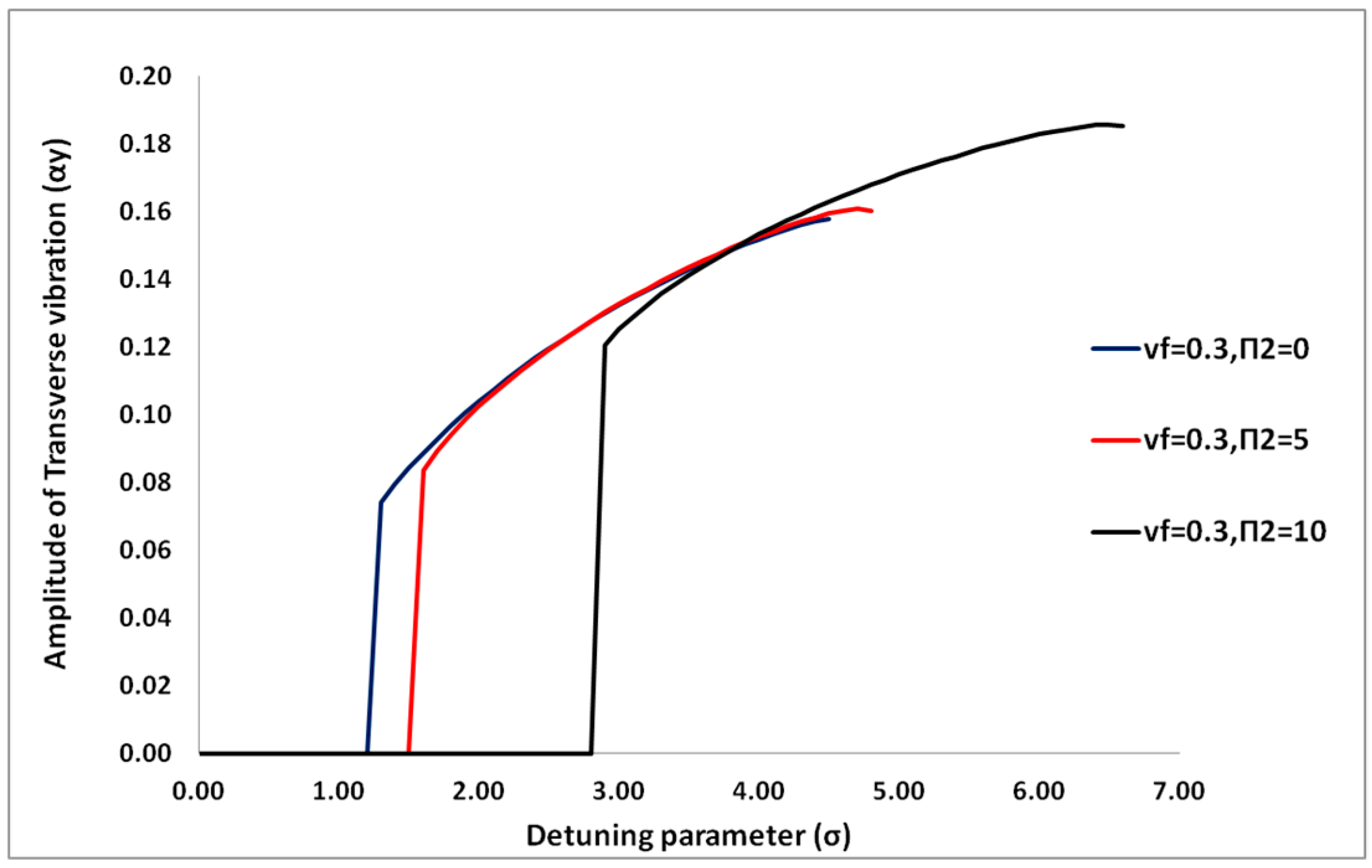
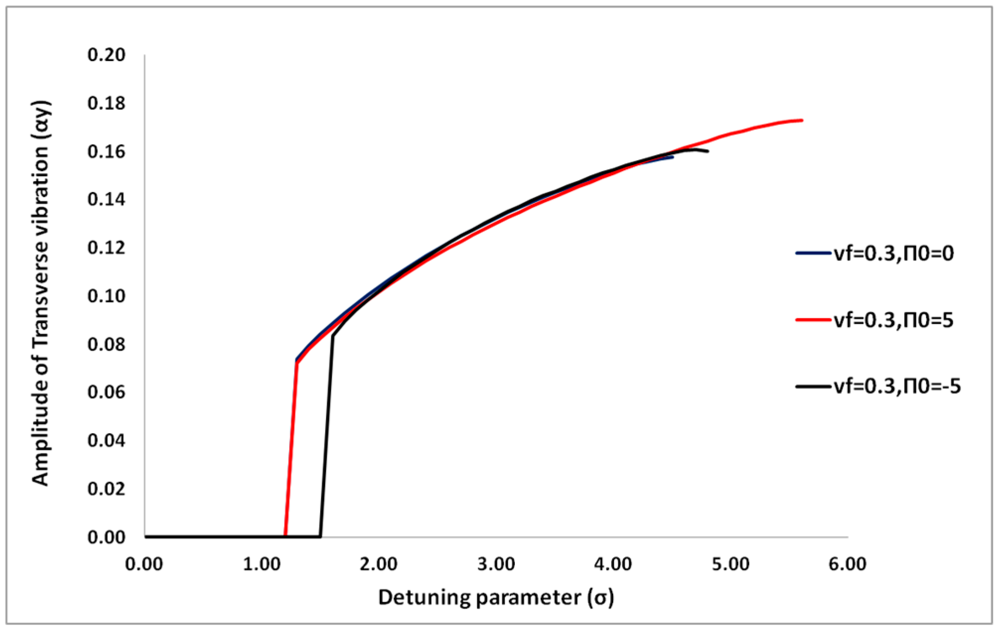
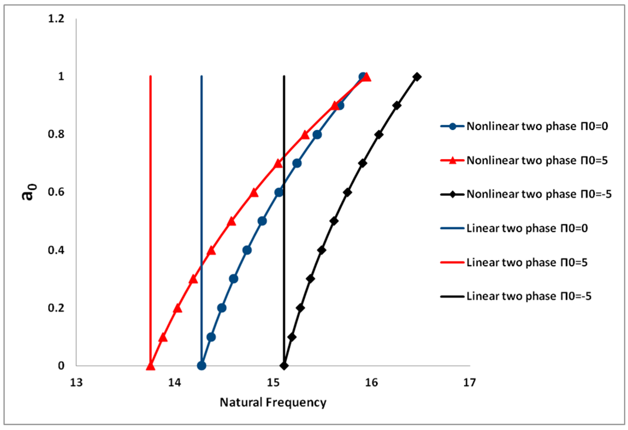
4.1.2. Effects of Flow Pressure on the Dynamic Behavior
4.1.3. Effects of Top Tension on the Dynamic Behavior
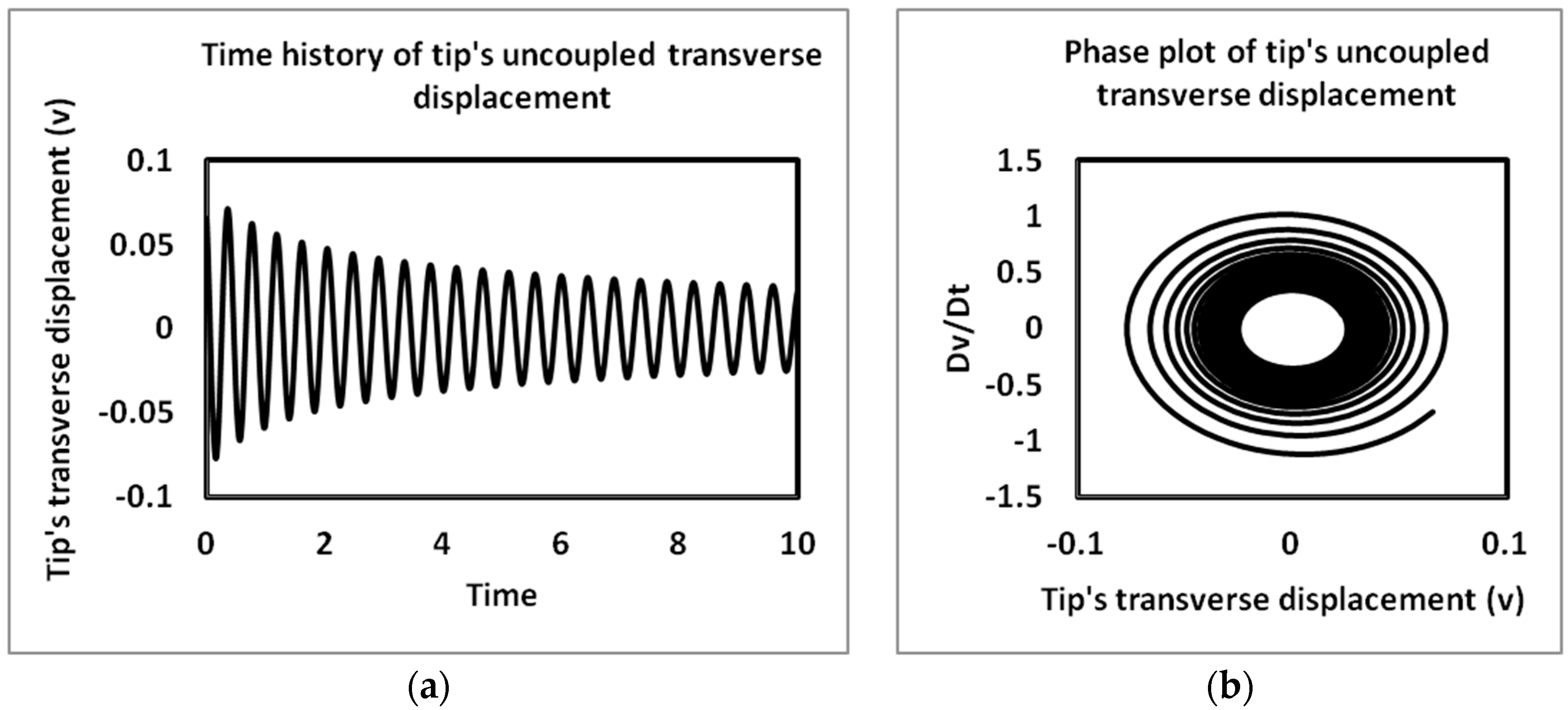
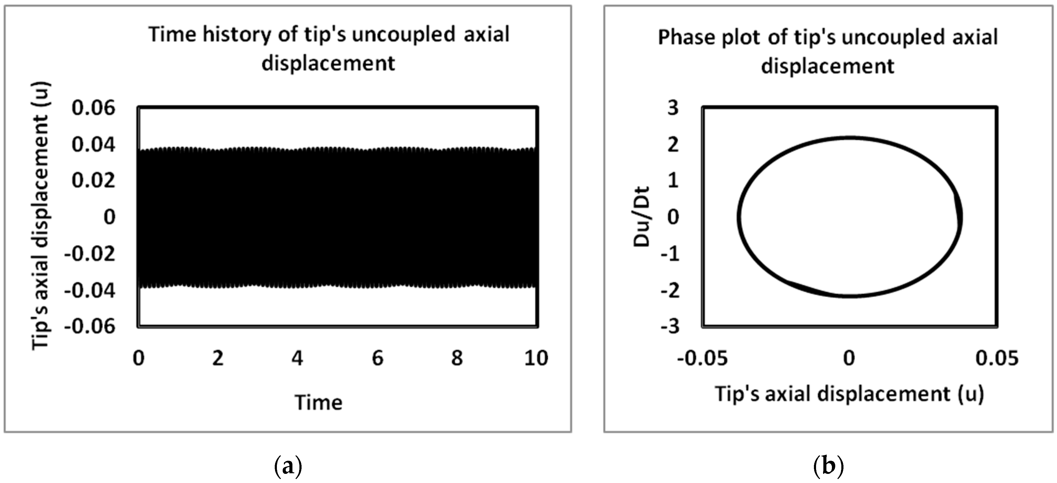
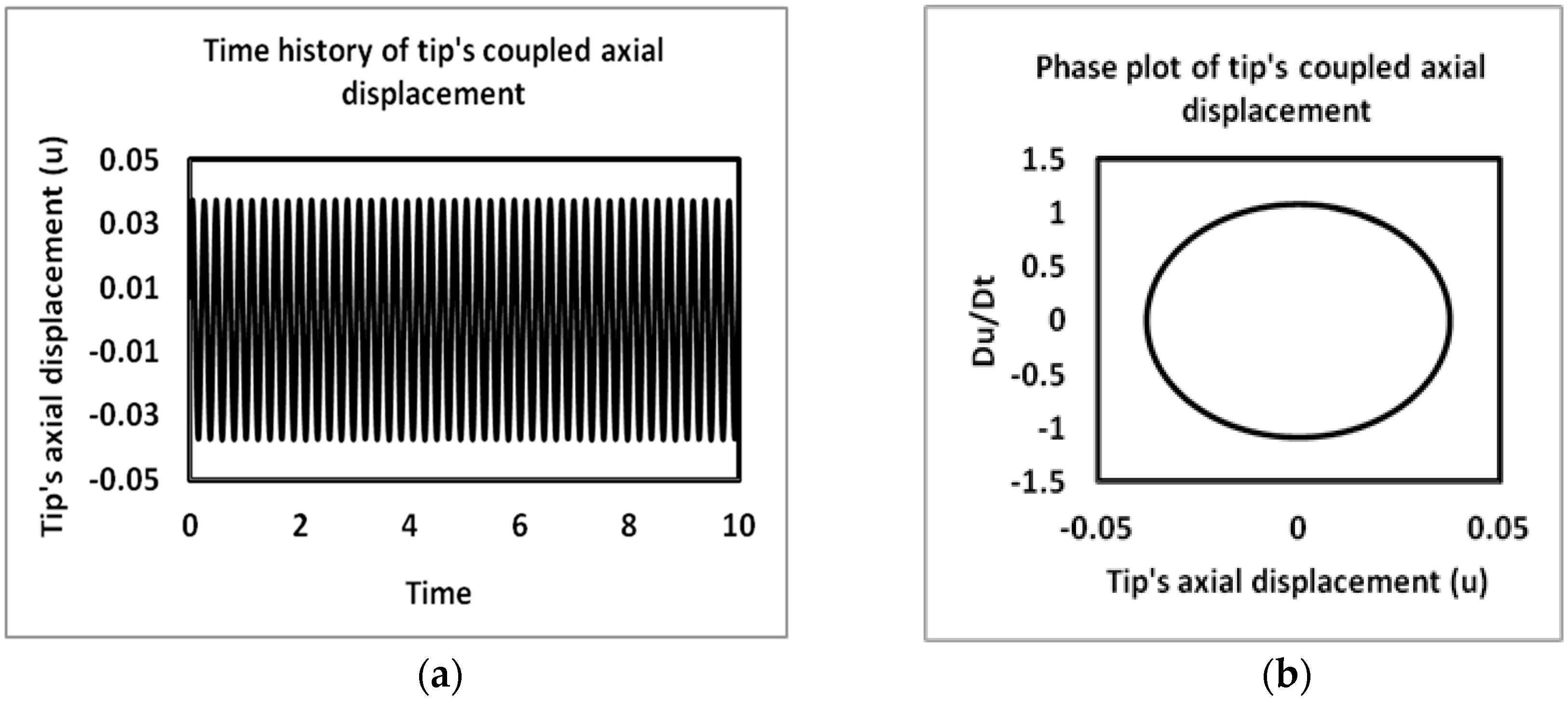
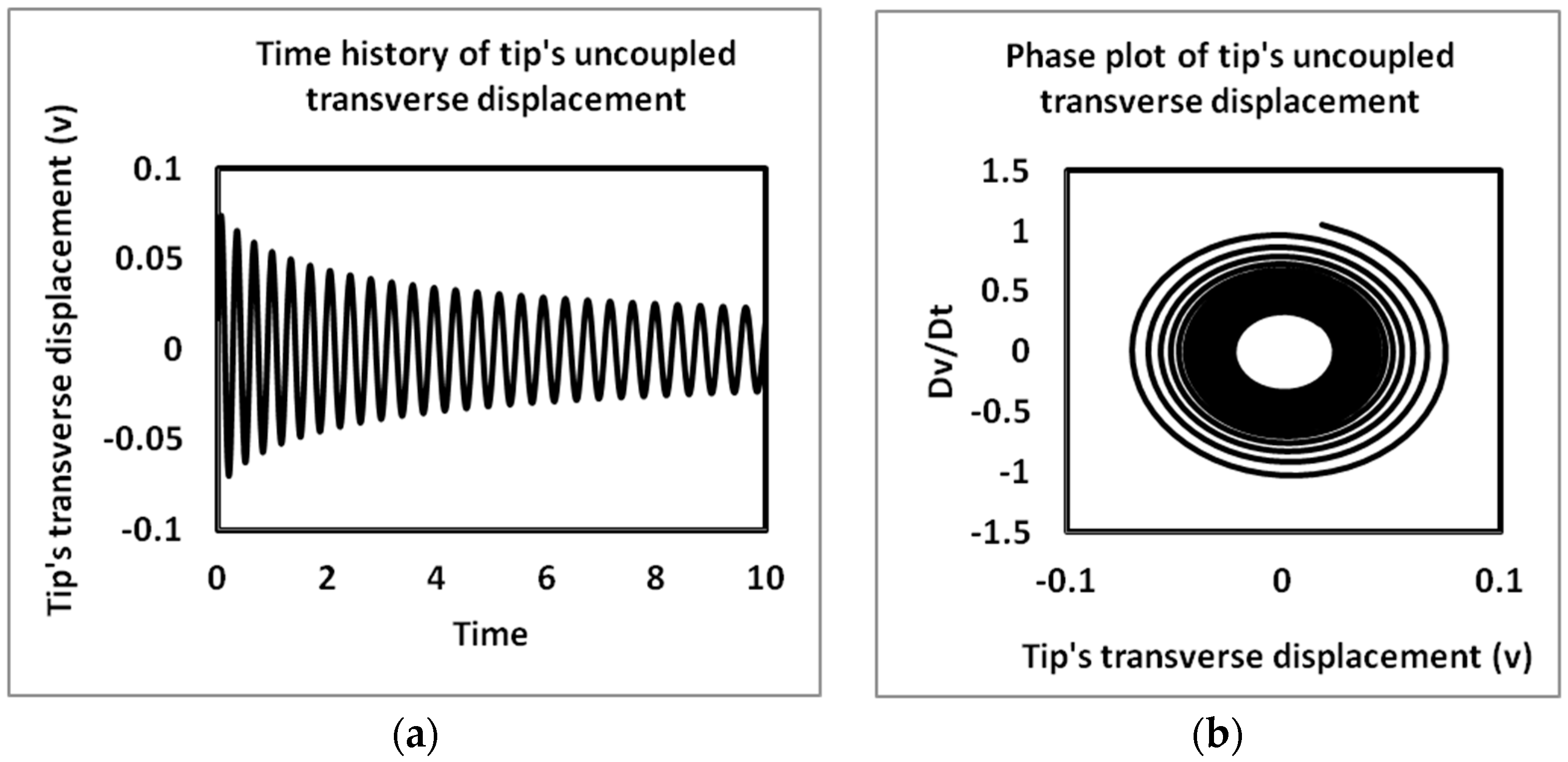
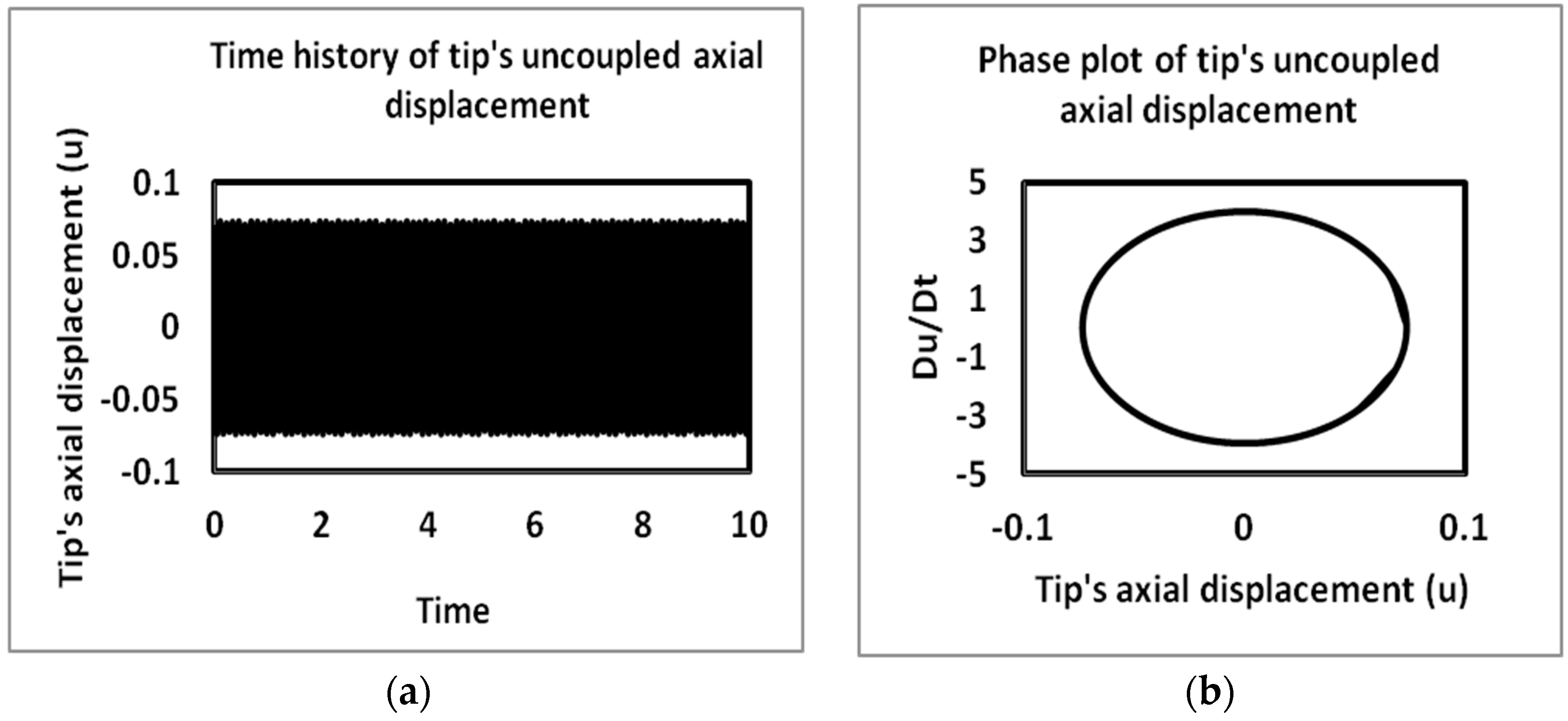
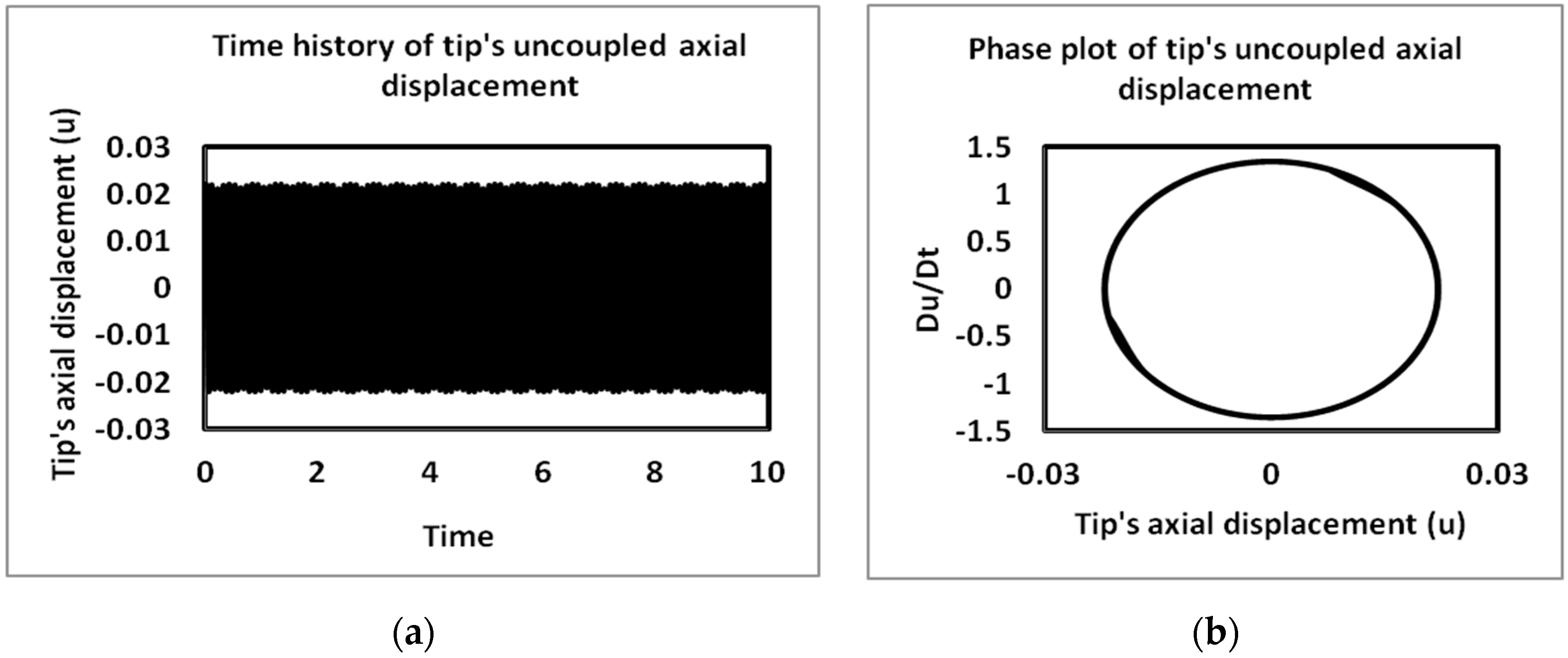
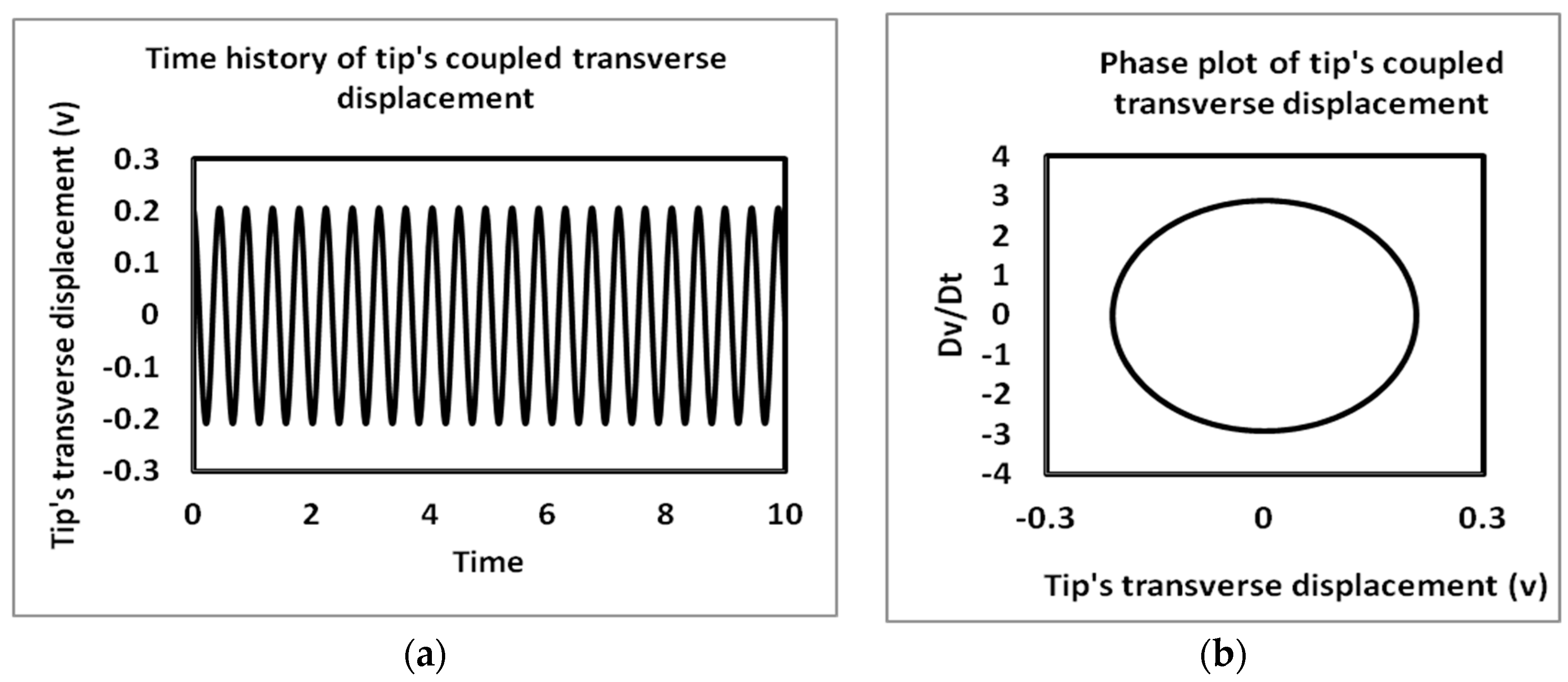
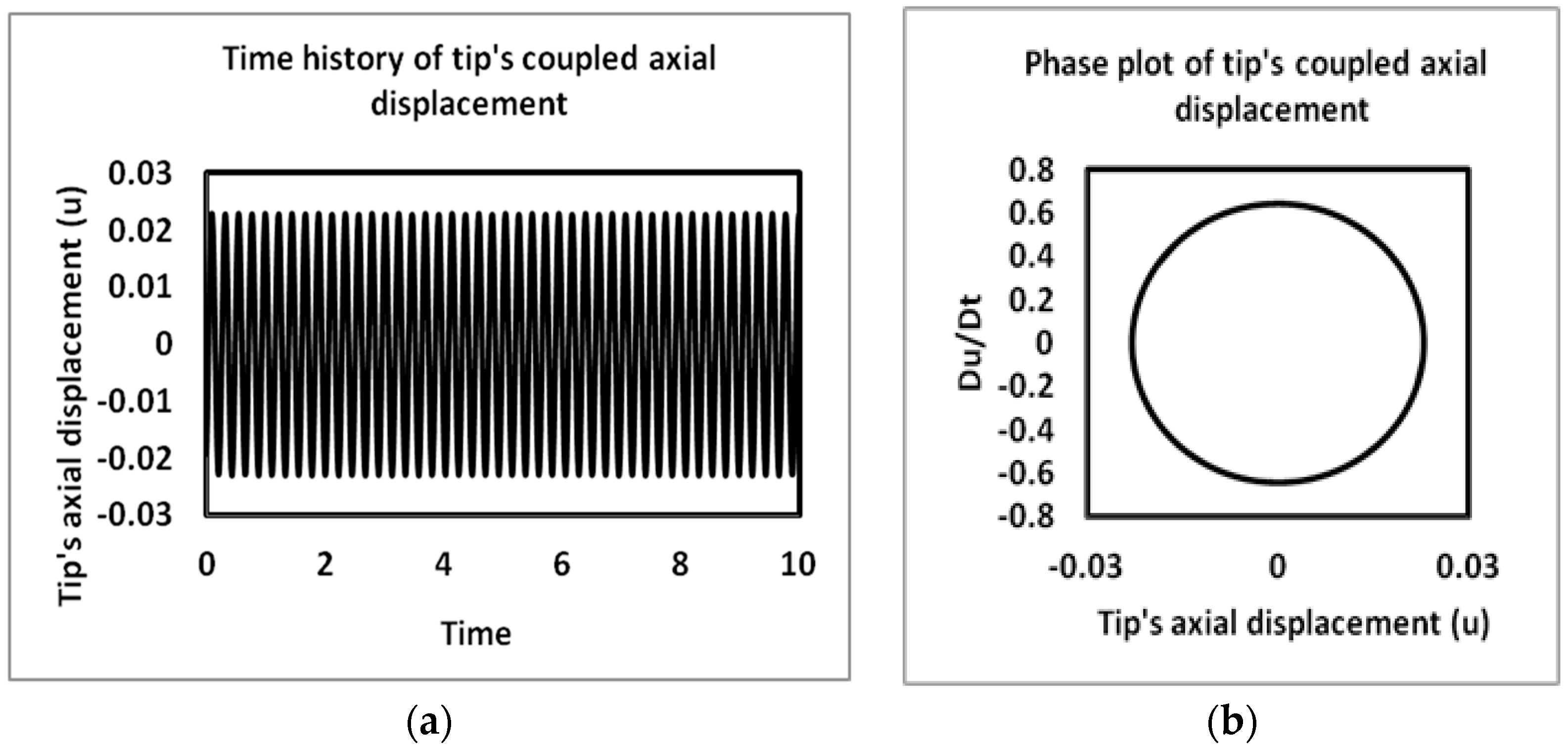
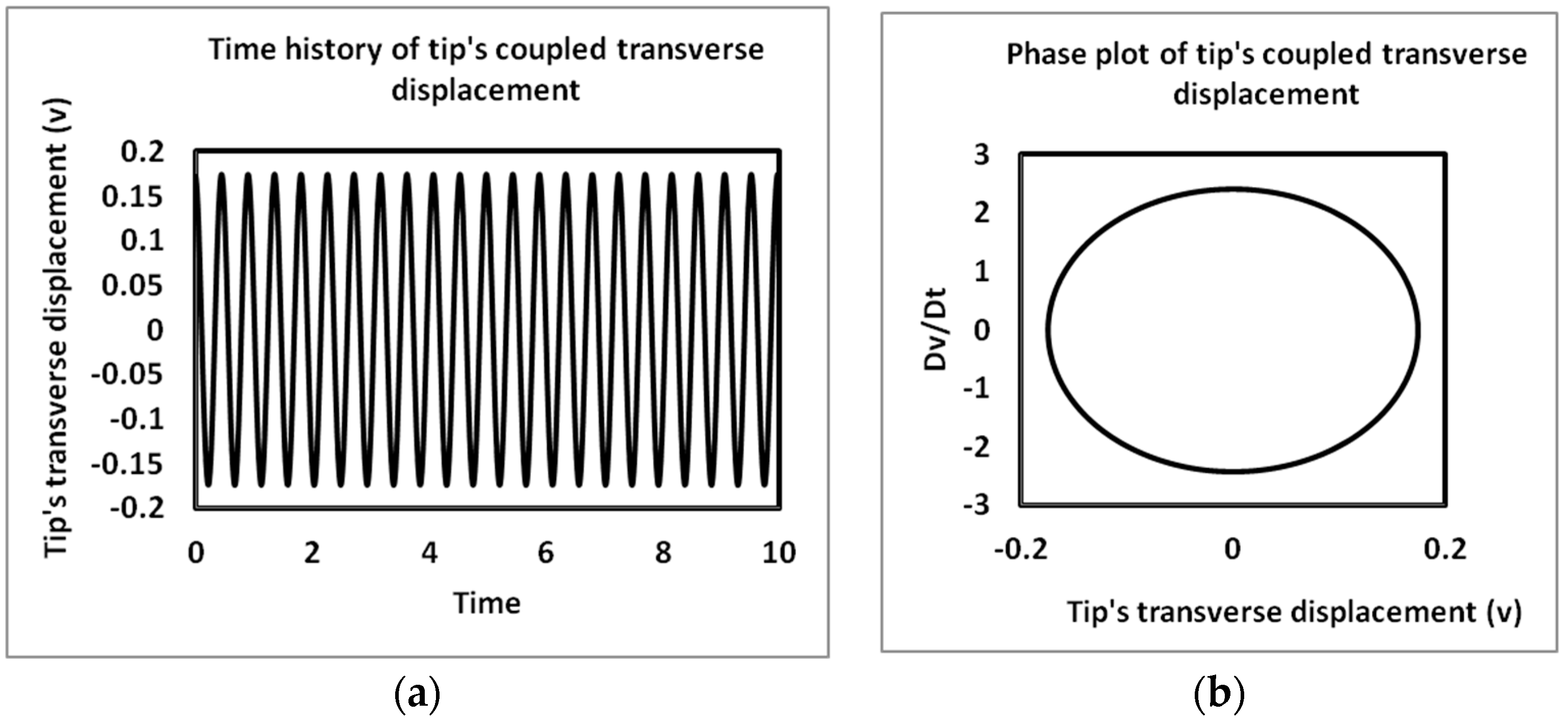
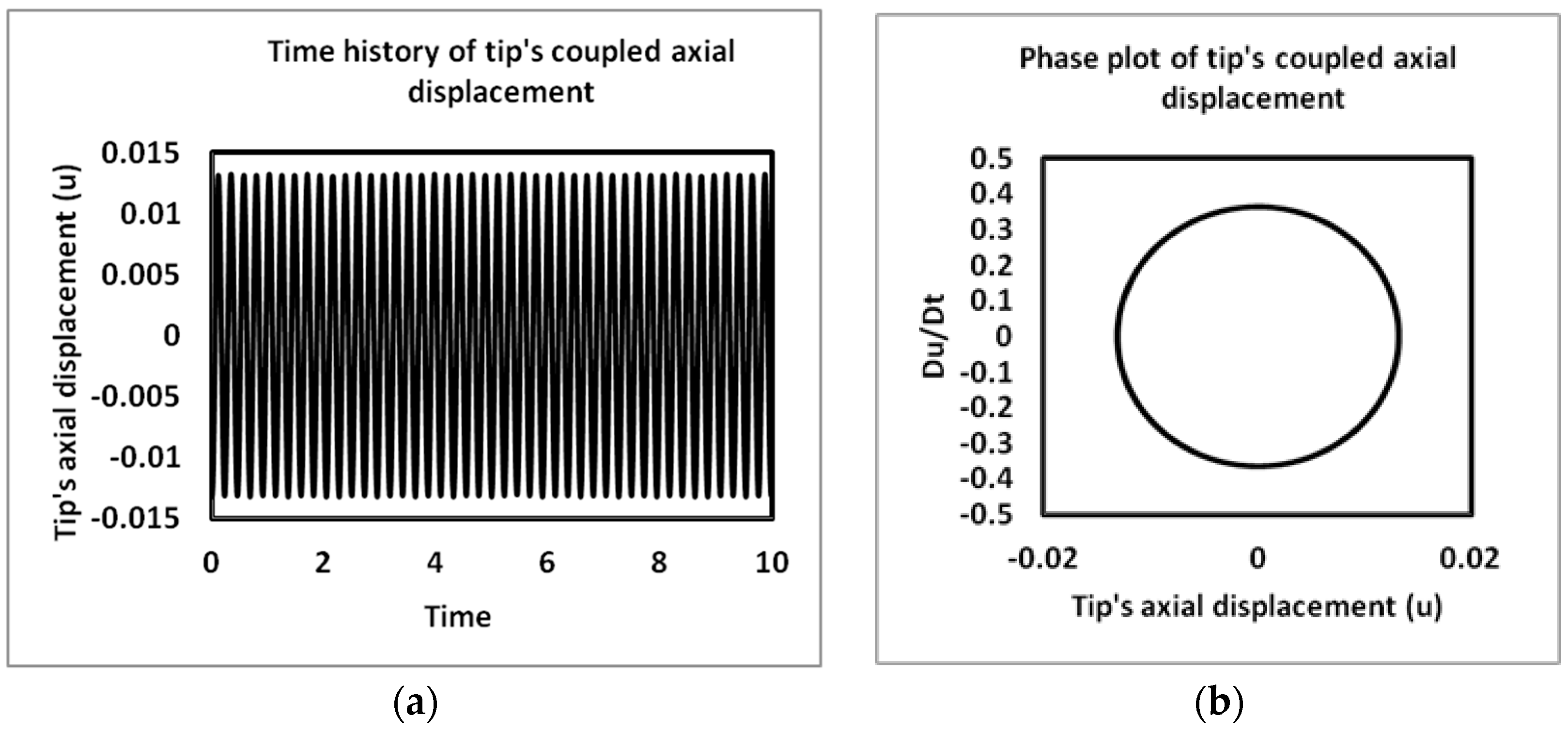
4.2. Time History and Phase Plots
5. Conclusions
Author Contributions
Conflicts of Interest
References
- Miwa, S.; Mori, M.; Hibiki, T. Two-phase flow induced vibration in piping systems. Prog. Nucl. Energy 2015, 78, 270–284. [Google Scholar] [CrossRef]
- Monette, C.; Pettigrew, M.J. Fluidelastic instability of flexible tubes subjected to two-phase internal flow. J. Fluids Struct. 2004, 19, 943–956. [Google Scholar] [CrossRef]
- Semler, C.; Li, G.X.; Païdoussis, M.P. The Nonlinear Equations of Motion of Pipes Conveying Fluid. J. Sound Vib. 1994, 169, 577–599. [Google Scholar] [CrossRef]
- Gregory, R.W.; Païdoussis, M.P. Unstable oscillation of tubular cantilevers conveying fluid. I. Theory. Proc. R. Soc. Lond. Ser. A Math. Phys. Sci. 1966, 293, 512–527. [Google Scholar] [CrossRef]
- Shilling, R.; Lou, Y.K. An Experimental Study on the Dynamic Response of a Vertical Cantilever Pipe Conveying Fluid. J. Energy Resour. Technol. 1980, 102, 129–135. [Google Scholar] [CrossRef]
- Ghayesh, M.H.; Païdoussis, M.P.; Amabili, M. Nonlinear dynamics of cantilevered extensible pipes conveying fluid. J. Sound Vib. 2013, 332, 6405–6418. [Google Scholar] [CrossRef]
- Łuczko, J.; Czerwiński, A. Parametric vibrations of pipes induced by pulsating flows in hydraulic systems. J. Theor. Appl. Mech. 2014, 52, 719–730. [Google Scholar]
- Païdoussis, M.P. Fluid-Structure Interactions: Slender Structures and Axial Flow; Elsevier Academic Press: London, UK, 2003. [Google Scholar]
- Sadeghi, Y.M.; Païdoussis, M.P. Nonlinear Dynamics of Extensible Fluid-Conveying Pipes, Supported at Both Ends. J. Fluids Struct. 2009, 25, 535–543. [Google Scholar] [CrossRef]
- Dai, L.W.H.L.; Qian, Q. Dynamics of simply supported fluid-conveying pipes with geometric imperfections. J. Fluids Struct. 2012, 29, 97–106. [Google Scholar]
- Sinir, B.G. Bifurcation and chaos of slightly curved pipes. Math. Comput. Appl. 2010, 3, 490–502. [Google Scholar] [CrossRef]
- Ritto, T.G.; Soize, C.; Rochinha, F.A.; Sampaio, R. Dynamic stability of a pipe conveying fluid with an uncertain computational model. J. Fluids Struct. 2014, 49, 412–426. [Google Scholar] [CrossRef]
- Chen, L.Q.; Zhang, Y.L.; Zhang, G.C.; Ding, H. Evolution of the double-jumping in pipes conveying fluid flowing at the supercritical speed. Int. J. Non-Linear Mech. 2014, 58, 11–21. [Google Scholar] [CrossRef]
- Yang, T.; Yang, X.; Li, Y.; Fang, B. Passive and adaptive vibration suppression of pipes conveying fluid with variable velocity. J. Vib. Control 2014, 20, 1293–1300. [Google Scholar] [CrossRef]
- Nayfeh, A.H. Finite Amplitude Longitudinal Waves in Non-uniform Bars. J. Sound Vib. 1975, 42, 357–361. [Google Scholar] [CrossRef]
- Nayfeh, A.H. Perturbation Methods; Wiley-VCH: Weinheim, Germany, 2004. [Google Scholar]
- Kesimli, A.; Bağdatlı, S.M.; Çanakcı, S. Free vibrations of fluid conveying pipe with intermediate support. Res. Eng. Struct. Mater. 2016, 2, 75–87. [Google Scholar]
- Oz, H.R.; Boyaci, H. Transverse vibrations of tensioned pipes conveying fluid with time-dependent velocity. J. Sound Vib. 2000, 236, 259–276. [Google Scholar] [CrossRef]
- EnZ, S. Effect of asymmetric actuator and detector position on Coriolis flowmeter and measured phase shift. Flow Meas. Instrum. 2010, 21, 497–503. [Google Scholar] [CrossRef]
- Yang, X.; Yang, T.; Jin, J. Dynamic stability of a beam-model viscoelastic pipe for conveying pulsative fluid. Acta Mech. Solida Sin. 2007, 20, 350–356. [Google Scholar] [CrossRef]
- Oz, H.R.; Pakdemirli, M. Vibrations of an axially moving beam with time-dependent velocity. J. Sound Vib. 1999, 227, 239–257. [Google Scholar] [CrossRef]
- Sinir, B.G.; Demir, D.D. The analysis of nonlinear vibrations of pipe conveying ideal fluid. Eur. J. Mech. B/Fluids 2015, 52, 38–44. [Google Scholar] [CrossRef]
- Woldesemayat, M.A.; Ghajar, A.J. Comparison of void fraction correlations for different flow patterns in horizontal and upward inclined pipes. Int. J. Multiph. Flow 2007, 33, 347–370. [Google Scholar] [CrossRef]
- Thomsen, J.J. Vibrations and Stability; Springer: Berlin, Germany, 2003. [Google Scholar]
- Nayfeh, A.H.; Mook, D.T. Nonlinear Oscillations; John Wiley and Sons, Inc.: Hoboken, NJ, USA, 1995. [Google Scholar]
- Sadaghi, Y.M.; Paidoussis, M.P.; Semler, C. A nonlinear model for an extensible slender flexible cylinder subjected to axial flow. J. Fluids Struct. 2005, 21, 609–627. [Google Scholar] [CrossRef]
- Oueini, S.S.; Chin, C.M.; Nayfeh, A.H. Dynamics of Cubic Nonlinear Vibration Absorber. Nonlinear Dyn. 1999, 20, 283–295. [Google Scholar] [CrossRef]
- Jo, H.; Yabuno, H. Amplitude reduction of parametric resonance by dynamic vibration absorber on quadratic nonlinear coupling. J. Sound Vib. 2010, 329, 2205–2217. [Google Scholar] [CrossRef]
- Rees, E.L. General Discussion of the Roots of a Quartic Equation. Am. Math. Mon. 1922, 29, 51–55. [Google Scholar] [CrossRef]


| Parameter Name | Parameter Unit | Parameter Values |
|---|---|---|
| External Diameter | Do (m) | 0.0113772 |
| Internal Diameter | Di (m) | 0.00925 |
| Length | L (m) | 0.1467 |
| Pipe density | ρpipe (kg/m3) | 7800 |
| Gas density | ρGas (kg/m3) | 1.225 |
| Water density | ρWater (kg/m3) | 1000 |
| Tensile and compressive stiffness | EA (N) | 7.24 × 10⁶ |
| Bending stiffness | EI (N) | 1.56 × 10³ |
| Fluid | Void Fraction | Liquid | Gas | Liquid | Gas | Critical Velocity | |
|---|---|---|---|---|---|---|---|
| Transverse | Axial | ||||||
| Single Phase | NA | 0.2 | 0.0 | 1.0 | 0.0 | 5.653 | 14.149 |
| Fluid | Void Fraction | Liquid | Gas | Liquid | Gas | Critical Mixture Velocity | |
|---|---|---|---|---|---|---|---|
| Transverse * | Axial | ||||||
| Two-Phase | 0.3 | 0.19998 | 0.00010 | 0.99948 | 0.00052 | 12.505 | 31.634 |
| Two-Phase | 0.4 | 0.19997 | 0.00016 | 0.99918 | 0.00082 | 13.349 | 33.750 |
| Two-Phase | 0.5 | 0.19995 | 0.00024 | 0.99878 | 0.00122 | 14.613 | 36.966 |
| Parameter | Void Fraction | Thermal Expansivity | Critical Mixture Velocity | |
|---|---|---|---|---|
| Transverse * | Axial | |||
| DT = 0 | 0.3 | 0.002 | 12.505 | 31.634 |
| DT = 40 | 0.3 | 0.002 | 9.253 | 31.634 |
| DT = 50 | 0.3 | 0.002 | 8.237 | 31.634 |
| Parameter | Void Fraction | Critical Mixture Velocity | |
|---|---|---|---|
| Transverse * | Axial | ||
| 0.3 | 12.505 | 31.634 | |
| 0.3 | 10.596 | 31.634 | |
| 0.3 | 8.237 | 31.634 | |
| Parameter | Void Fraction | Critical Velocity | |
|---|---|---|---|
| Transverse * | Axial | ||
| 0.3 | 12.505 | 31.634 | |
| 0.3 | 14.155 | 31.634 | |
| 0.3 | 10.596 | 31.634 | |
© 2017 by the authors. Licensee MDPI, Basel, Switzerland. This article is an open access article distributed under the terms and conditions of the Creative Commons Attribution (CC BY) license (http://creativecommons.org/licenses/by/4.0/).
Share and Cite
Adegoke, A.S.; Oyediran, A.A. The Analysis of Nonlinear Vibrations of Top-Tensioned Cantilever Pipes Conveying Pressurized Steady Two-Phase Flow under Thermal Loading. Math. Comput. Appl. 2017, 22, 44. https://doi.org/10.3390/mca22040044
Adegoke AS, Oyediran AA. The Analysis of Nonlinear Vibrations of Top-Tensioned Cantilever Pipes Conveying Pressurized Steady Two-Phase Flow under Thermal Loading. Mathematical and Computational Applications. 2017; 22(4):44. https://doi.org/10.3390/mca22040044
Chicago/Turabian StyleAdegoke, Adeshina S., and Ayo A. Oyediran. 2017. "The Analysis of Nonlinear Vibrations of Top-Tensioned Cantilever Pipes Conveying Pressurized Steady Two-Phase Flow under Thermal Loading" Mathematical and Computational Applications 22, no. 4: 44. https://doi.org/10.3390/mca22040044
APA StyleAdegoke, A. S., & Oyediran, A. A. (2017). The Analysis of Nonlinear Vibrations of Top-Tensioned Cantilever Pipes Conveying Pressurized Steady Two-Phase Flow under Thermal Loading. Mathematical and Computational Applications, 22(4), 44. https://doi.org/10.3390/mca22040044