Article

A Four-Variable Shear Deformation Theory for the Static Analysis of FG Sandwich Plates with Different Porosity Models

by
Rabab A. Alghanmi
* and
Rawan H. Aljaghthami
Department of Mathematics, College of Sciences and Arts, King Abdulaziz University, Rabigh 21911, Saudi Arabia
*
Author to whom correspondence should be addressed.
Math. Comput. Appl. 2024, 29(2), 20; https://doi.org/10.3390/mca29020020
Submission received: 27 January 2024 / Revised: 29 February 2024 / Accepted: 6 March 2024 / Published: 8 March 2024

Abstract

:
This study is centered on examining the static bending behavior of sandwich plates featuring functionally graded materials, specifically addressing distinct representations of porosity distribution across their thickness. The composition of the sandwich plate involves a ceramic core and two face sheets with functionally graded properties. Mechanical loads with a sinusoidal distribution are applied to the sandwich plate, and a four-variable shear deformation theory is employed to establish the displacement field. Notably, this theory involves only four unknowns, distinguishing it from alternative shear deformation theories. Equilibrium equations are derived using the virtual work concept, and Navier’s method is applied to obtain the solution. The study addresses the impact of varying porosities, inhomogeneity parameters, aspect ratios, and side-to-thickness ratios on the static bending behavior of the sandwich plates. The influence of various porosities, inhomogeneity parameter, aspect ratio, and side-to-thickness ratio of the sandwich plates are explored and compared in the context of static bending behavior. The three porosity distributions are compared in terms of their influence on the bending behavior of the sandwich plate. The findings indicate that a higher porosity causes larger deflections and Model A has the highest central deflection. Adopting the four-variable shear deformation theory demonstrated its validity since the results were similar to those obtained in the literature. Several important findings have been found, which could be useful in the construction and application of FG sandwich structures. Examples of comparison will be discussed to support the existing theory’s accuracy. Further findings are presented to serve as benchmarks for comparison.

1. Introduction

Functionally graded materials (FGMs) represent a category of engineered material characterized by a gradual change in composition, microstructure, as well as characteristics across a given volume. These materials are intended to optimize performance by customizing material properties to specific requirements, resulting in improved functionality and performance when compared to typical homogeneous materials [1,2]. FGMs are used in a variety of industries, including aerospace, automotive, medicinal, and energy. Numerous studies have been carried out to examine the mechanical and thermal characteristics of structures made from FGM [3,4,5,6,7,8,9,10,11,12,13].
Sandwich plates with FGMs are composite structures that consist of a core material sandwiched between two face sheets and have a graded variation in composition, microstructure, or characteristics in at least one of the components (core or face sheets). Functionally graded sandwich plates provide benefits such as increased strength-to-weight ratio, increased load-bearing capacity, and customized mechanical properties. Because the materials are graded, they can be optimized for performance and functionality in certain regions of the construction. Since the sandwich configuration and functionally graded layers allow for customization performance, these structures are suited for a wide range of engineering applications.
Several studies have been published on the static and dynamic behaviors of sandwich plates under different conditions. A two-dimensional solution for the bending, buckling, and free vibration of a novel three-layer sandwich plate with FG faces was developed by Zenkour [14,15]. Analytical approaches for bending, free vibration, and buckling of rectangular FG sandwich plates were provided by Thai et al. [16], which included different boundary conditions following a new first-order shear deformation theory (FSDT). A higher-order shear deformation theory was adopted by Nguyen et al. [17] as well as an edge-based strain approach to analyze the static and vibration behavior of isotropic and FG sandwich plates. A static analysis of FG sandwich plates was conducted by Mantari and Granados [18] through a novel FSDT. In [19], A mechanical bending analysis of two FG sandwich plates was conducted, exploring different boundary conditions through the finite strip approach in accordance with the refined plate theory (RSPT). The work of adopting the finite strip approach in accordance with refined plate theory (RSPT). Hirane et al. [20] introduced a fixed high order layered finite element model (FEM) to look into the static and free vibration of FG sandwich plates according to various boundary conditions. For parametrically examining the free vibration behavior of the FG sandwich plate with a homogenous core, a reliable and effective computational method was developed by Cho [21]. This numerical approach was built on hierarchical models derived from the accuracy of the spectrum model and the 2-D natural element method. Monajati et al. [22] present a new RSPT-based approach for examining the vibration and buckling of FG plates. The Airy stress function excludes in-plane variables, resulting in only two state variables: transverse bending and transverse shear deformation.
During the fabrication of functionally graded materials (FGMs), voids or porosities naturally occur within the material [23]. The idea of functionally graded materials with porosities integrates the concept of FGMs with the presence of pores or voids within the material structure. This integration can result in better qualities such as weight reduction, thermal insulation improvement, and specialized functional characteristics. Several researchers [24,25,26,27,28] were interested in the buckling analysis of porous FGM structures. Additionally, the vibration of FG porous structures has been explored by different researchers [29,30,31,32,33,34,35,36].
Static bending of FG plates with porosity has been investigated in many studies. The study provided by Zenkour and Radwan [37] explained how bending analysis of FG porous plates is affected if consideration is given to moisture and temperature. FG porous plates were analyzed by Alghanmi and Zenkour [38] for static bending with the existence of piezoelectric fiber-reinforced composite (PFRC) layer attached to the plates using a quasi-three-dimensional (3D) theory RSPT, while in article [39], they applied a sinusoidal shear deformation theory to examine the bending behavior considering porosity in FG plates with a PFRC layer. The effect of porosities on the dynamic analysis of FG sandwich plates was studied by Benferhat et al. [40], where the plates are simply supported, using a new refined shear deformation theory which includes transverse shear deformation effects. Porous FG sandwich plates were studied under the effect of bending, vibration, and buckling using the FEM integrated with hyperbolic shear deformation theory. The author concluded that plates of any form and boundary conditions can be evaluated using the current finite element algorithm, and when the porosity effect is included, an increase is observed in the deflection and critical buckling load. The pattern of porosity distribution affected the tendency of natural frequency change. As a result, the position and distribution of porosity have a significant impact on the FG sandwich plates with porosity behavior [41]. In [42], the effect of porosities was investigated on composite nanoplates under hygrothermal conditions in the perspective of 3D elasticity. The assumed plate was extended over a two-parameter polymeric medium. They proposed a quasi-3D elasticity analysis in addition to the theory of nonlocal continuum as a method of solving.
The study of Alghanmi [43] considered static analysis of nanoplates composed of FGMs containing porosities. To model these nanoplates, the research integrated the nonlocal strain gradient theory (NSGT) with a four-variable shear deformation theory. FG sandwich plates composed of piezoelectric faces seized the attention of different research works. The research of [44] employed the two-variable shear deformation plate theory to explore stress and deformation analysis of sandwich plates. These plates feature a core with functionally graded properties and faces composed of piezoelectric materials. They examined the impact of sinusoidal loadings that encompass hygro-thermal-electro-mechanical aspects.
The static behavior of porous plates was studied alongside a functional gradient to characterize the impact of the shear correction factor related to FSDT [45]. The buckling characteristic of FG porous plates adopting a quasi-3D refined theory was examined by Zenkour and Aljadani [46]. The consequence of thickness stretching and the three types of FG porous plates were considered in this investigation. The exploration of how porosity distribution affects the static and buckling response of an FG porous plate was investigated by Dhuria et al. [47]. To simulate the porous FG plate, an inverse hyperbolic shear deformation theory with an inverse hyperbolic shear strain function is adopted.
The most recent work on the structural analysis of FGMs was presented by Alghanmi [48]. In that investigation, an NSGT was constructed to examine the bending of sandwich nanoplates featuring FG porous cores and electromagnetic layers. The FG sandwich nanoplates were characterized using a four-variable shear deformation theory and two distinct porosity distribution models.
Several studies have delved into the bending of the FG sandwich plate, referring to the review studies. A more thorough examination of the studies on the impact of porosity finds various gaps and inconsistencies. Limited investigations have been conducted in the domain of FG sandwich plates influenced by porosity. The distribution of FGM material constituents should then be associated with porosities. A further in-depth investigation of the porosity factor contribution to FG sandwich plates is required. This study was devoted to illustrating the influence of the porosity operator, given that there is a scarcity of research on porosities in the literature. The displacement field is determined through a four-variable shear deformation theory. Interestingly, there are just four unknowns in this theory. Three models of porosity distributions are considered in a rectangular FG sandwich plate under mechanical loading. The three porosity models are compared in terms of their influence on the bending behavior of the plate.

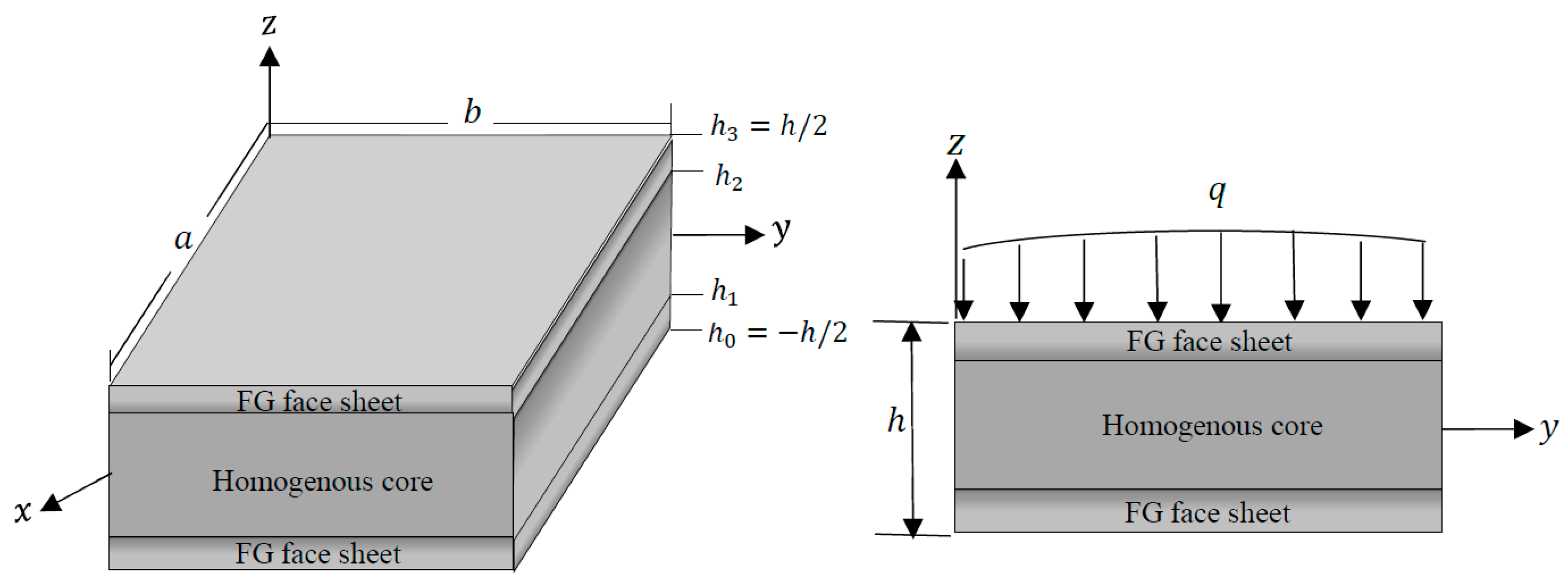
2. Theoretical Model and Formulas

The sandwich plate, illustrated in Figure 1 with dimensions of length a , width b , and thickness h , with the middle plane defined by z = 0 . Comprising three layers, the upper and lower layers are constructed from functionally graded material of ceramic and metal, while the middle layer is composed of pure ceramic/metal. The FG sandwich plate experiences a distributed mechanical load q ( x , y ) at its top surface ( z = h / 2 ) .

2.1. Material Properties and Porosity Models

Most studies use the Voigt and Mori–Tanaka schemes for analyzing functionally graded plates and structures. The Voigt model has been used in the majority of FG structure assessments because it is simple to calculate and can be used to set upper and lower bounds on a heterogeneous material’s effective elastic characteristics. It provides a conservative estimate, which may be one of the reasons why most researchers have utilized the rule of mixture. Based on Voigt’s rule of mixture, the material properties P , Young’s modulus and Poisson’s ratio, of each layer of the sandwich plate with perfect FG face layers can be expressed by the following formulas [14]:
P 1 z = P m + P c P m V 1 z , P 2 z = P m + P c P m V 2 z , P 3 z = P m + P c P m V 3 z ,
where P ( 1 ) , P ( 2 ) , and P ( 3 ) are the material properties related to the first, second, and third layers, respectively. P c and P m indicate the material properties of ceramic and metal, respectively. In addition, V 1 z , V 2 z , and V 3 z are the volume fractions [14] of ceramic with respect to the total volume for the first, second, and third FG layers, respectively, as indicated in Equation (2).
V 1 z = z h 0 h 1 h 0 k , h 0 z h 1 , V 2 z = 1 , h 1 z h 2 , V 3 z = z h 3 h 2 h 3 k , h 2 z h 3 ,
where h 0 = h / 2 and h 3 = h / 2 indicate the bottom and top faces, respectively, and k ( k 0 ) specifies the volume fraction index. In this study, the sandwich plate exhibits symmetry and is constructed with three layers of equal thickness. Therefore, the inner interfaces are set to h 1 = h / 6 and h 2 = h / 6 .
This research proposes three models of porosity distribution across the plate thickness in addition to the case of perfect FG layers which contain no porosity. The models are named A, B, and C, and they differ according to the pattern of porosity distribution across the plate thickness. Therefore, the material properties for each type varies with the z coordinate according to the following [41,49].

2.1.1. FG with Even Porosities (Model A)

The porosities in Model A are uniformly spread across the thickness direction of the FG layers, thus their material properties can be represented as follows [41,49]:
P 1 z = P m + P c P m V 1 z α 2 P c + P m , P 2 z = P m + P c P m V 2 z , P 3 z = P m + P c P m V 3 z α 2 P c + P m ,
where α indicates the porosity coefficient which is much less than 1 and it takes the value of zero in the absence of porosity.

2.1.2. FG with Uneven Porosities (Model B)

In this model, the porosities are distributed unevenly across the thickness direction of the FG layers. Therefore, the material properties of each layer can be defined based on the following functions [41,49]:
P 1 z = P m + P c P m V 1 z α 2 P c + P m 1 2 z h 0 + h 1 h 1 h 0 , P 2 z = P m + P c P m V 2 z , P 3 z = P m + P c P m V 3 z α 2 P c + P m 1 2 z h 2 + h 3 h 3 h 2 ,

2.1.3. FG with Linear-Uneven Porosities (Model C)

The porosities in this model are spread unevenly and linearly over the thickness. The functions that follow can be used to define the material attributes for each layer [41,49].
P 1 z = P m + P c P m V 1 z α 2 P c + P m 1 z h 1 h 0 h 1 , P 2 z = P m + P c P m V 2 z , P 3 z = P m + P c P m V 3 z α 2 P c + P m z h 3 h 2 h 3 ,

2.2. Displacement Field and Constitutive Equations

The displacement model for the FG porous sandwich plate is introduced through a four-variable shear deformation theory as [50]
u 1 x , y , z = u x , y z w b x f z w s x , u 2 x , y , z = v x , y z w b y f z w s y , u 3 x , y , z = w b x , y + w s x , y ,
in which u and v are the displacements in the x and y directions at the middle of the plate, respectively; w b ,   w s are the displacements in the z direction resulting from bending moment and shear forces, respectively; and f z = z 4 + 5 3 z 3 h 2 , which describes the variation in transverse shear stresses across the thickness of the FG sandwich, is regarded as the shape function [51]. The strain–displacement relationships are provided by the linear elasticity theory as
ε x x = u x z 2 w b x 2 f z 2 w s x 2 ,    ε y y = v y z 2 w b y 2 f ( z ) 2 w s y 2 , γ y z = w s y 1 f z , γ x z = w s x 1 f z , γ x y = u y + v x 2 z 2 w b x y + f z 2 w s x y ,
The constitutive equation for the FG porous sandwich plate can be written as
σ x σ y τ y z τ x z τ x y = c 11 c 12 0 0 0 c 12 c 22 0 0 0 0 0 c 44 0 0 0 0 0 c 55 0 0 0 0 0 c 66 ε x ε y γ y z γ x z γ x y ,
The plate stiffness coefficients c i j have been designated by
c 11 = c 22 = E ( z ) 1 ν 2 ( z ) , c 12 = ν ( z ) E ( z ) 1 ν 2 ( z ) ,    c 44 = c 55 = c 66 = E ( z ) 2 ( 1 + ν ( z ) ) ,
where E ( z ) denotes Young’s modulus and ν ( z ) denotes Poisson’s ratio, which are mentioned in Equations (3)–(5).

3. Governing Equations

The governing equations are deduced using the virtual work principle, as presented in the following equation:
h / 2 h / 2 Ω σ x δ ε x + σ y δ ε y + τ x y δ γ x y + τ y z δ γ y z + τ x z δ γ x z d Ω d z Ω q δ u 3 d Ω = 0
where q is the load distributed the top surface of the sandwich plate. By substituting Equation (7) into Equation (10) and integrating across the thickness, Equation (10) becomes:
Ω N x x δ u x M x x 2 δ w b x 2 S x x 2 δ w s x 2 + N y y δ v y M y y 2 δ w b y 2 S y y 2 δ w s y 2 + N x y δ u y + N x y δ v x 2 M x y 2 δ w b x y 2 S x y 2 δ w s x y + Q y z δ w s y + Q x z δ w s x q δ w b q δ w s } d Ω = 0 ,
where the stress resultants N i j , M i j ,   S i j , and Q i z are characterized as
N i j , M i j , S i j = n = 1 3 h n 1 h n σ i j n 1 , z , f z d z , i , j = x , y , Q i 3 = n = 1 3 h n 1 h n τ i z ( n ) 1 f z d z , i = x , y ,
where h n and h n 1 are the top and bottom z -coordinates of the nth layer. After integrating Equation (11) by parts and substituting δ u , δ v , δ w b , and δ w s to zero, the following equilibrium equations result:
N x x x + N x y y = 0 , N x y x + N y y y = 0 , 2 M x x x 2 + 2 2 M x y x y + 2 M y y y 2 + q = 0 , 2 S x x x 2 + 2 2 S x y x y + 2 S y y y 2 + Q x z x + Q y z y + q = 0 ,
By including the constitutive equations from Equations (6)–(8) into Equation (12), the stress resultants for the sandwich plate can take the following forms:
N x x = A 1 u x A 2 2 w b x 2 A 3 2 w s x 2 + A 4 v y A 5 2 w b y 2 A 6 2 w s y 2 , N y y = A 4 u x A 5 2 w b x 2 A 6 2 w s x 2 + A 7 v y A 8 2 w b y 2 A 9 2 w s y 2 , M x x = A 2 u x A 10 2 w b x 2 A 11 2 w s x 2 + A 5 v y A 12 2 w b y 2 A 13 2 w s y 2 , M y y = A 5 u x A 12 2 w b x 2 A 13 2 w s x 2 + A 8 v y A 14 2 w b y 2 A 15 2 w s y 2 , S x x = A 3 u x A 11 2 w b x 2 A 16 2 w s x 2 + A 6 v y A 13 2 w b y 2 A 17 2 w s y 2 , S y y = A 6 u x A 13 2 w b x 2 A 17 2 w s x 2 + A 9 v y A 15 2 w b y 2 A 18 2 w s y 2 , N x y = A 19 u y + v x 2 A 20 2 w b x y + A 21 2 w s x y , M x y = A 20 u y + v x 2 A 22 2 w b x y + A 23 2 w s x y , S x y = A 21 u y + v x 2 A 23 2 w b x y + A 24 2 w s x y , Q y z = A 25 w s y , Q x z = A 26 w s x ,
The constants provided in the previous equations are defined as follows:
A 1 A 2 A 3 A 4 A 5 A 6 A 7 A 8 A 9 = h 2 h 2 c 11 c 12 c 22 1 z f z d z , A 10 A 11 A 16 A 12 A 13 A 17 A 14 A 15 A 18 = h 2 h 2 c 11 c 12 c 22 z 2 z f ( z ) f 2 ( z ) d z , A 19 A 20 A 21 A 22 A 23 A 24 = h 2 h 2 c 66 1 z f ( z ) z 2 z f ( z ) f 2 ( z ) d z , { A 25 , A 26 } = h 2 h 2 c 44 , c 55 1 f z 2 d z ,

4. Solution Method

The sandwich plate is chosen to be simply supported along all edges. The boundary conditions can thus be represented as follows:
v = w b = w s = w b y = w s y = N x = M x = S x = 0 , a t    x = 0 , a , u = w b = w s = w b x = w s x = N y = M y = S y = 0 , a t    y = 0 , b . ,
The solution is obtained using Navier’s method. According to this solution, the mechanical load can be represented as follows for the case of sinusoidal load distribution:
q = q 0 sin α x sin β y ,
where α = π / a , and β = π / b . As for q 0 , it denotes the intensity of q x , y . Navier proposed the following solutions for u , v ,   w b , w s , which satisfy the indicated boundary conditions:
u v ( w b , w s ) = U cos α x sin β y V sin αx cos β y ( W b , W s ) sin α x sin β y ,
where ( U , V , W b , W s ) are arbitrary parameters to be obtained. With the help of Equations (17) and (18), one can easily convert Equation (13) to obtain the following algebraic system equation:
A Δ = F ,
where Δ = U , V , W b , W s and F = 0 , 0 , q 0 , q 0 . Appendix A contains the nonzero entries a i j = a j i of the symmetric matrix [A].

5. Results and Discussion

In this section, numerical results are presented for the bending of sandwich plates with faces made with functionally graded porous materials and metal/ceramic core.

5.1. Material Properties

The numerical solution is obtained for sandwich plates composed of aluminum and zirconia. The Young’s modulus is 70 GPa for aluminum and 151 GPa for zirconia. The Poisson’s ratio is taken as 0.3 for both materials. Despite the fact that the Poisson’s ratios are the same for both materials, the effective Poisson’s ratio varies with thickness due to the inclusion of the porosity effect.

5.2. Nondimensional Parameters

The calculated stresses and deflections are presented in dimensionless forms as follows
w ¯ = 10 h E 0 a 2 q 0 u 3 a 2 , b 2 , z ¯ , σ ¯ x = h 2 a 2 q 0 σ x a 2 , b 2 , z ¯ , τ ¯ x z = h a q 0 τ x z 0 , b 2 , z ¯ , τ ¯ x y = h a q 0 τ x y 0 , 0 , z ¯ , z ¯ = z h ,
in which the reference variable is set to E 0 = 1 GPa and q 0 = 100 N/m2.

5.3. Comparison and Validation

For the purpose of verification, sandwich plates with functionally graded faces and a ceramic core are considered first without the inclusion of the porosity factor. The results of the dimensionless central deflection w ¯ are obtained for different plate aspect ratios b / a and compared with the solutions found in other references. The comparison is displayed in Table 1. The results of dimensionless central deflection w ¯ obtained by Zenkour [14] by implementing four plate theories: classical plate theory (CPT), first-order shear deformation theory (FSDT), third-order shear deformation theory (TSDT), and the sinusoidal shear deformation theory (SSDT). The results in Table 1 are obtained for different schemes. The schemes mentioned in Table 1 are constructed with different values of h 1 and h 2 as follows:
1-0-1 :   h 1 = 0 ,   h 2 = 0
2-1-2 :   h 1 = h / 10 ,   h 2 = h / 10
1-1-1 :   h 1 = h / 6 ,   h 2 = h / 6
2-2-1 :   h 1 = h / 10 ,   h 2 = 3 h / 10
1-2-1 :   h 1 = h / 4 ,   h 2 = h / 4
In the same table are given the results of the present study. It can be observed that the present results are almost identical to the results of the third-order shear deformation theory (TSDT). The results of the CPT theory are the farthest from the present results since the CPT does not consider shear deformation.

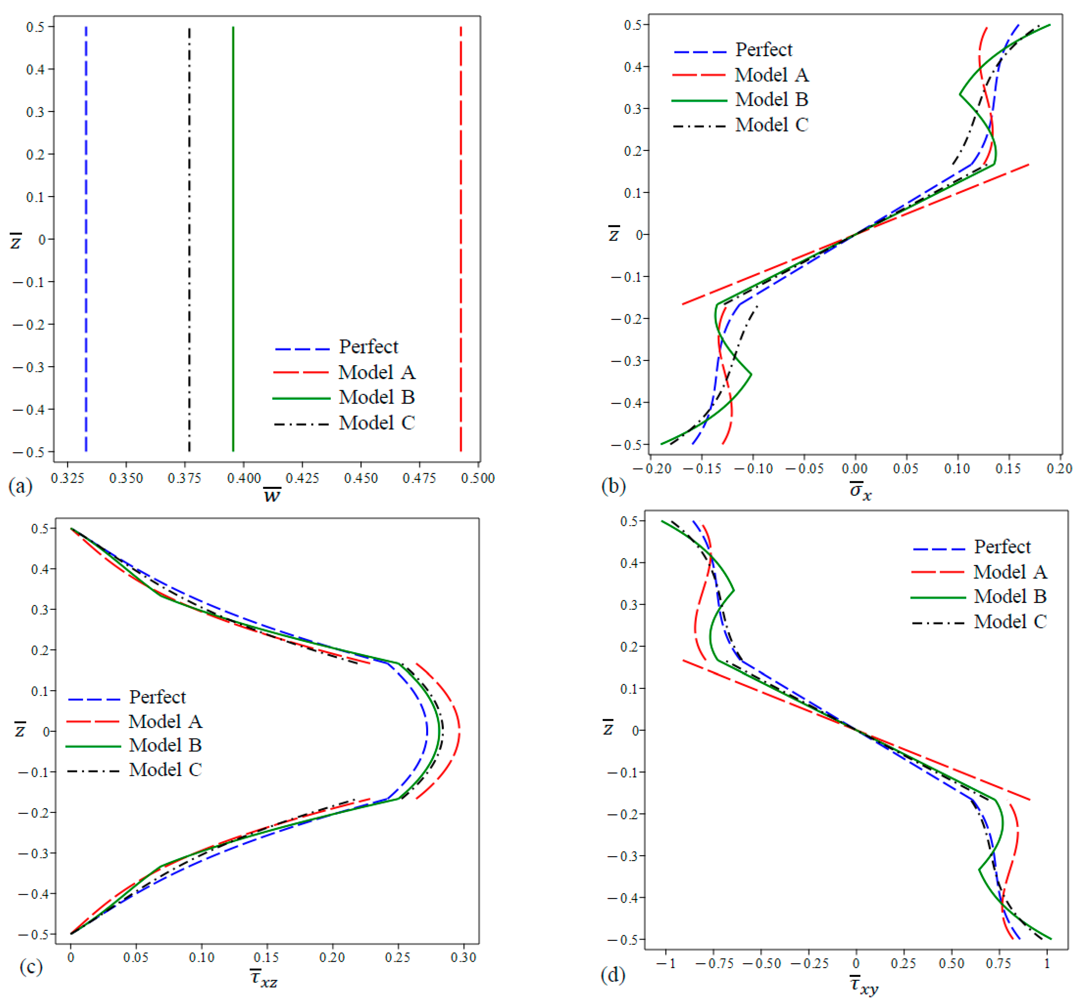
5.4. Bending Analysis of the FG Porous Sandwich Plates

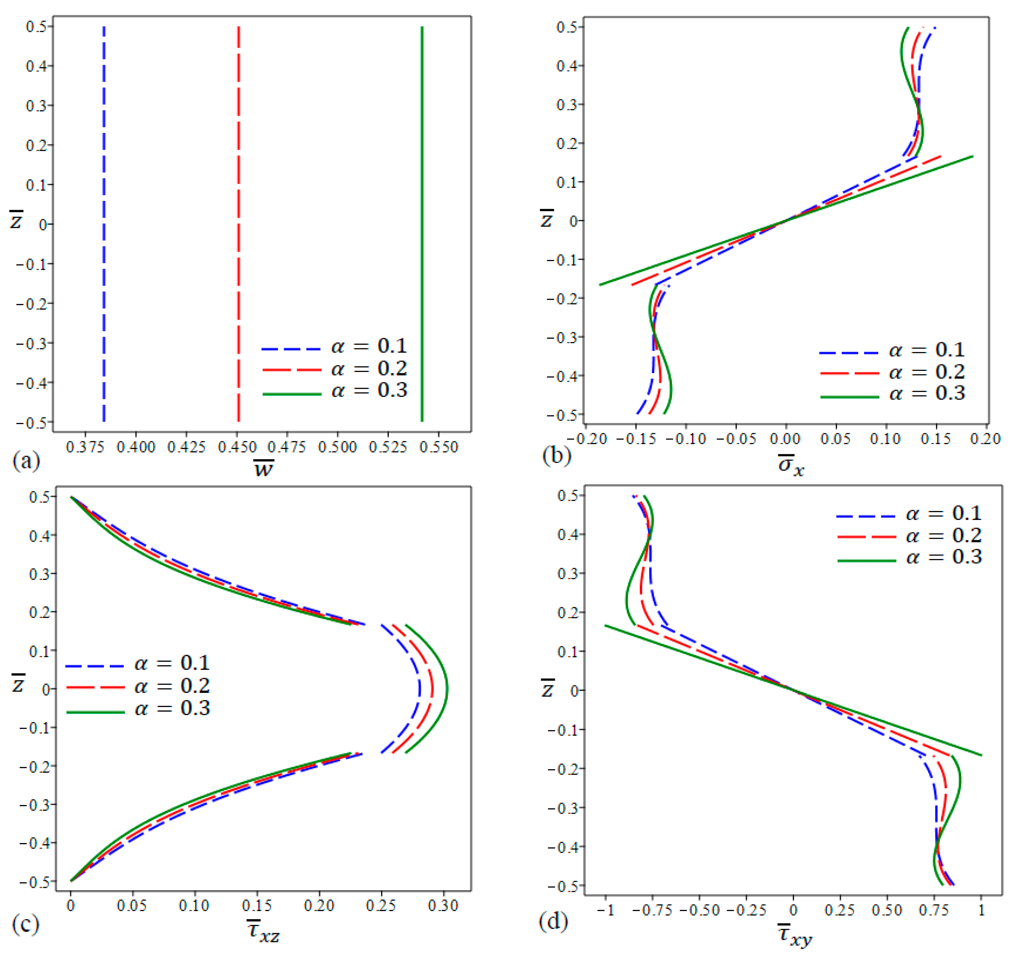
5.4.1. Sandwich Plates with Ceramic Core

As part of the bending analysis of the porous sandwich plate, it is important to explore the distribution of central deflection as well as the bending and shear stresses across the thickness of the plate. Through this analysis, the effect of porosity on the behavior of sandwich plates can be identified.
The comparison between the different porosity models at different porosity ratios for the nondimensional central deflection is summarized in Table 2. It can be noticed that at the same porosity coefficient ( α ), the central deflection is highest in the case of Model A followed by Model B, then Model C, with a higher difference in deflection observed between Models A and B (see Figure 9a). This is due to the reduction in the modulus of elasticity from the perfect model down to Model C, in the same order mentioned above. On the other hand, for each model, increasing the coefficient of porosity ( α ) results in the increase in deflection. Again, here, the increase in the deflection can be referred to the degradation of the modulus of elasticity as a result of intensifying the porosities in the external layers. In addition, as the plate length-to-thickness ratio ( a / h ) increases, the deflection values increase, which can be referred to as the reduction in the plate bending stiffness at higher values of length-to-thickness ratios ( a / h ).
As for the nondimensional normal stress ( σ ¯ x ) at the external surface of the plate, Table 3 shows that at the same porosity coefficient ( α ), the highest values are observed in Model B then it decreases in Model C, then Model A, which shows the lowest values. Within the same model, normal stress is inversely proportional with α . There can be noticed a significant drop in the normal stress when moving from zero porosity model (perfect model) to a porous model.
The nondimensional shear stress ( τ ¯ x z ) at the middle of the plate depth ( z = 0 ) shows the highest values in the case of Model A followed by Model C, then Model B at fixed porosity coefficient α (see Table 4). When the porosity coefficient ( α ) is increased for any model, the shear stress ( τ ¯ x z ) at ( z = 0 ) is also increased.
The nondimensional stress ( τ ¯ x y ) at ( z = h / 3 ) is highest in Model A followed by Model C, then Model B, considering fixed value of the porosity coefficient ( α ) (see Table 5). When the porosity coefficient ( α ) is increased for any model, the shear stress ( τ ¯ x y ) at ( z = h / 3 ) is reduced. This stress is also directly proportional to the length-to-thickness ratio ( a / h ) where the stress shows higher values at higher ( a / h ).
Figure 2 and Figure 3 demonstrate how the Young’s modulus of FG sandwich plates varies with porosity models A, B, and C in terms of volume fraction index and porosity factor, respectively. It is interesting to observe that Young’s modulus varies continuously at the interfaces for Model B, whereas it varies discontinuously for Models A and C. For all three models, as the volume fraction index and porosity factor increase, the variation in Young’s modulus loses smoothness throughout plate thickness.
In the case of FG sandwich plates with even porosity (Model A), the nondimensional central deflection distribution in a square FG sandwich plate shown in Figure 4a suggests that a higher porosity leads to larger deflections. This can be referred to as the degradation in the modulus of elasticity as a consequence of high porosities, which leads to a reduction in the bending stiffness of the plate and makes the plate less resistant to deflections. Furthermore, the deflection does not increase linearly with porosity. The deflection increases in an accelerated manner even with equal increments in the porosity coefficient. This indicates a rapid degradation in the modulus of elasticity, and thus the bending stiffness, as porosity increases. For the cases of FG sandwich plates with uneven porosities (Model B) and linear-uneven porosities (Model C), the nondimensional central deflection also increases at higher porosities. However, the increase takes almost a linear fashion with respect to the porosity coefficient (Figure 5a and Figure 6a).
The nondimensional stress distributions in the studied FG sandwich plate with even porosities (Model A) are shown in Figure 4b–d. The normal stress shear stresses become larger for higher porosity coefficients across the middle portion of plate thickness. This portion varies among the different types of stresses (60%, 33.3%, and 76%) of the plate thickness in the case of normal stress σ   ¯ x , shear stress τ ¯ x z , and shear stress τ ¯ x y , respectively. However, this trend is reversed beyond that range, i.e., in the upper and lower portions of plate thickness. In these portions, all types of stresses are reduced when porosity is increased.
In the case of FG plates with uneven porosities (Model B), the nondimensional central stresses show almost a similar trend as of Model A with a few differences (Figure 5b–d). The normal stress   σ ¯ x , shear stress τ ¯ x z , and shear stress τ ¯ x y show larger values at higher porosities in the middle 50%, 33.3%, and 50% of the plate thickness, respectively. The values of σ ¯ x and τ ¯ x y reverse twice beyond theses ranges (in the external portions of the thickness). In addition, the values of τ ¯ x z at different porosities converge to one value at the bottom and top boundaries of the external sheets, while they show higher values at lower porosities in the middle of the external sheets.
The nondimensional central stresses in FG plates with linear-uneven porosities (Model C) are observed to be higher at higher porosities in the middle sheet (Figure 6b–d). On the other hand, the shear stress τ ¯ x z is reduced at higher porosities in the external sheets and converges to one value at the very external faces of the plate for all levels of porosities. As for the stresses σ ¯ x and τ ¯ x y , they become inversely proportional with the porosity coefficient in the external sheets of the plate up to some point ( z ¯ = 0.4), after which they return to their original trend again (directly proportional to the porosity coefficient).
The effect of porosity on the nondimensional central deflection is compared at different aspect ratios and side-to-thickness ratios of the plate for Models A, B, and C as shown in Figure 7, Figure 8, and Figure 9, respectively. The indicated deflection decreases at higher values of the aspect ratio and at lower values of the side-to-thickness ratio. This fact is referred to as the increase in bending stiffness in both cases. However, regardless of the values of the aspect ratio and the side-to-thickness ratio, the nondimensional central deflection is always smaller at a higher porosity.
The normal stress distribution across the thickness of the plate is displayed in Figure 10b for the different porosity models at a fixed α = 0.25. As the length-to-thickness ratio increases, the normal stress ( σ ¯ x ) slightly decreases in all models. Across the external layers, the normal stress ( σ ¯ x ) is highest in Model B followed by Model A, the perfect model, then Model C up to some point. Beyond this point, this trend is reversed. However, in the middle nonporous layer, the normal stress ( σ ¯ x ) is highest in Model A followed by Model B, Model C, then the perfect model.
The nondimensional shear stress ( τ ¯ x z ) is plotted against the depth z ¯ of the plate in Figure 10c for different porosity models at a constant α = 0.25. As the length-to-thickness ratio of the plate increases, most values of the shear stress ( τ ¯ x z ) increase except for a few values. Across the external layers, the perfect model and Model C exhibit higher stresses compared to the other models over most of the external layers. On the other hand, across the middle nonporous layer, the maximum shear stress ( τ ¯ x z ) is apparent in Model A followed by Model C, Model B, and then the perfect model.
Figure 10d shows that across the thickness, the curves of τ ¯ x y indicate higher shear stress values for the perfect model and Model C in the external porous layers compared to Model A. However, the opposite trend can be noticed in the middle nonporous layer.
It is worth mentioning that the main challenge in sandwich structures is the sudden shift in material properties throughout the interfaces between the face layers and the core. The smoothly and continuously varying material properties of FG materials eliminate this problem by allowing for the continuous change in the material properties at the interfaces. However, in the presence of even (Model A) and linear-uneven (Model C) porosities, the variation in axial stress and transverse shear stress loses its smoothness and becomes slightly discontinuous at the interfaces.
The change in the nondimensional central deflection according to the change in plate geometry is illustrated in Figure 11. The nondimensional deflection peaks at an aspect ratio of 1 as shown in Figure 11a, which is the case of square plates and starts to decrease at higher aspect ratios. At higher aspect ratios, the width decreases which magnifies the bending stiffness of the plate, which reduces the central deflection. In Figure 11b, it can be observed that the nondimensional deflection increases at higher length-to-thickness ratios ( a / h ) because higher values of a / h means lower bending stiffness of the plate. Generally speaking, regardless of the values of a / b and a / h , the nondimensional central deflection is always highest for Model A followed by Model B, Model C, and then the perfect model.
The effect of varying k values defined in the volume fraction equations (Equation (2)) on the nondimensional stresses and central deflection is displayed in Figure 12. Model B with α = 0.1 is selected for the comparison. Higher values of k result in higher central defections. The normal stress ( σ ¯ x ) also increases at higher k values across the middle nonporous layer. This trend is reversed twice in the external porous layers. The shear stress ( τ ¯ x z ) curves associated with k = 1 , 2 are close to each other and show much higher values compared to the shear stress curve associated with k = 4 which shows accelerated reduction in the shear stress values at higher k values. In the case of the shear stress ( τ ¯ x y ), lower k values lead to lower shear stress across the middle nonporous layer. This trend is reversed twice in the external porous layers.

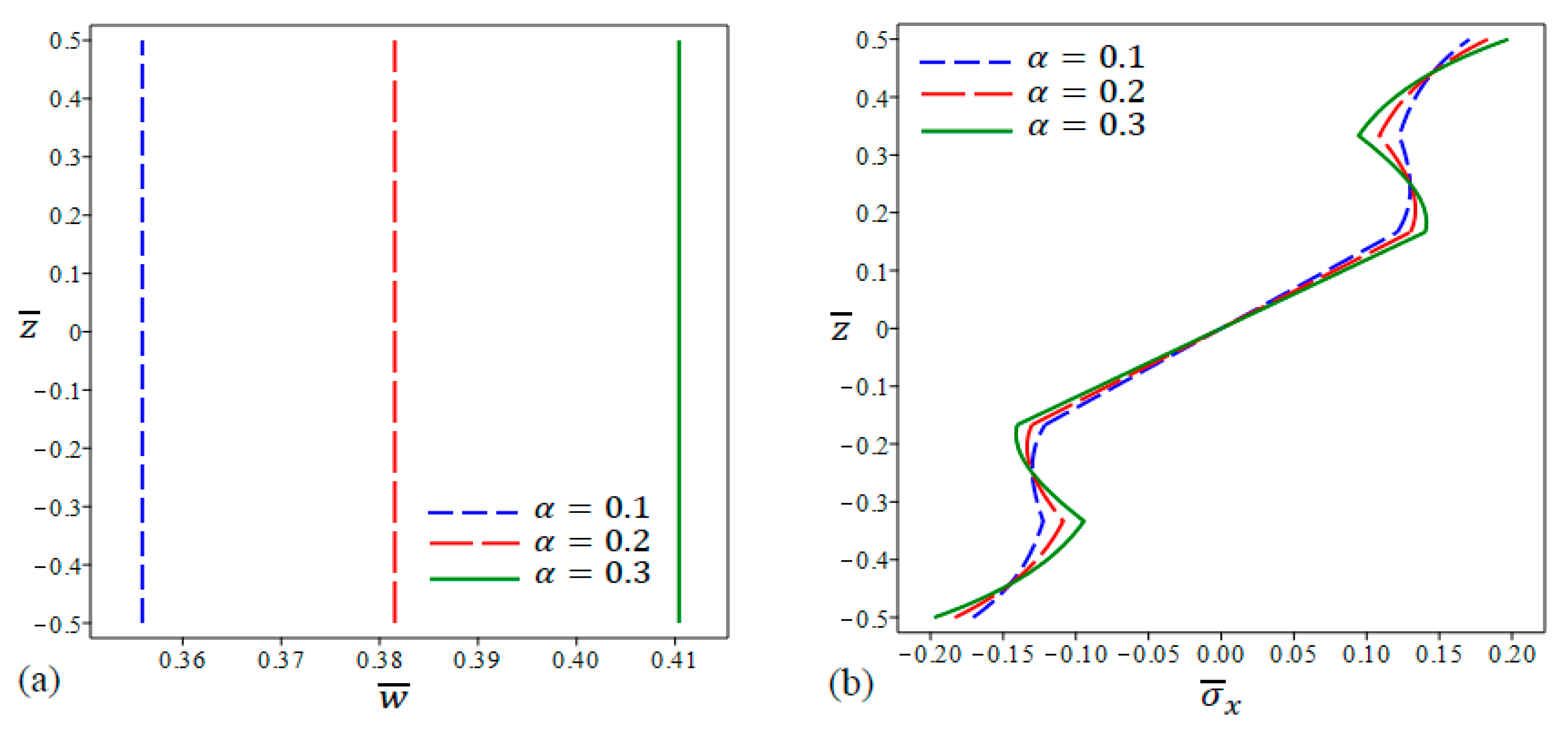
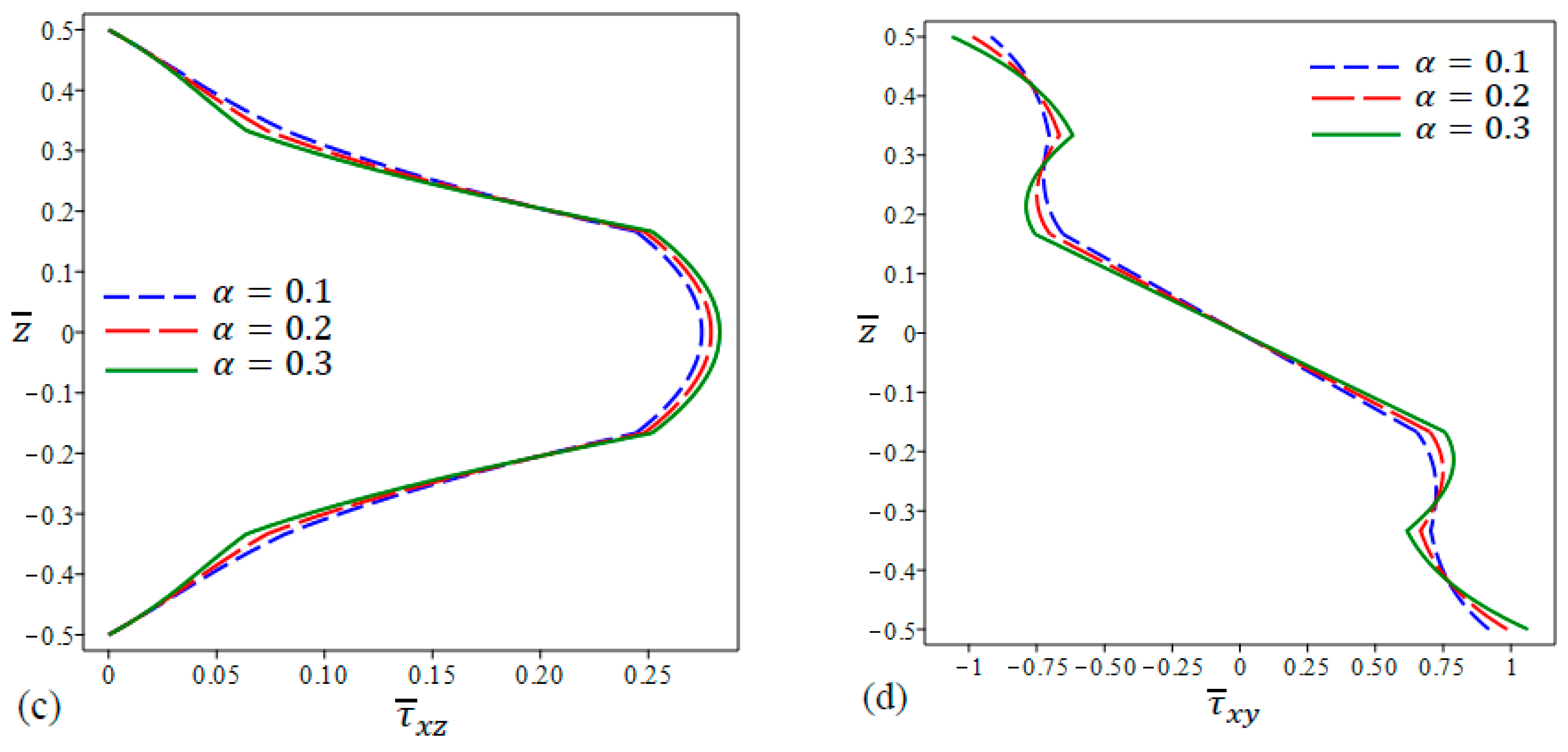
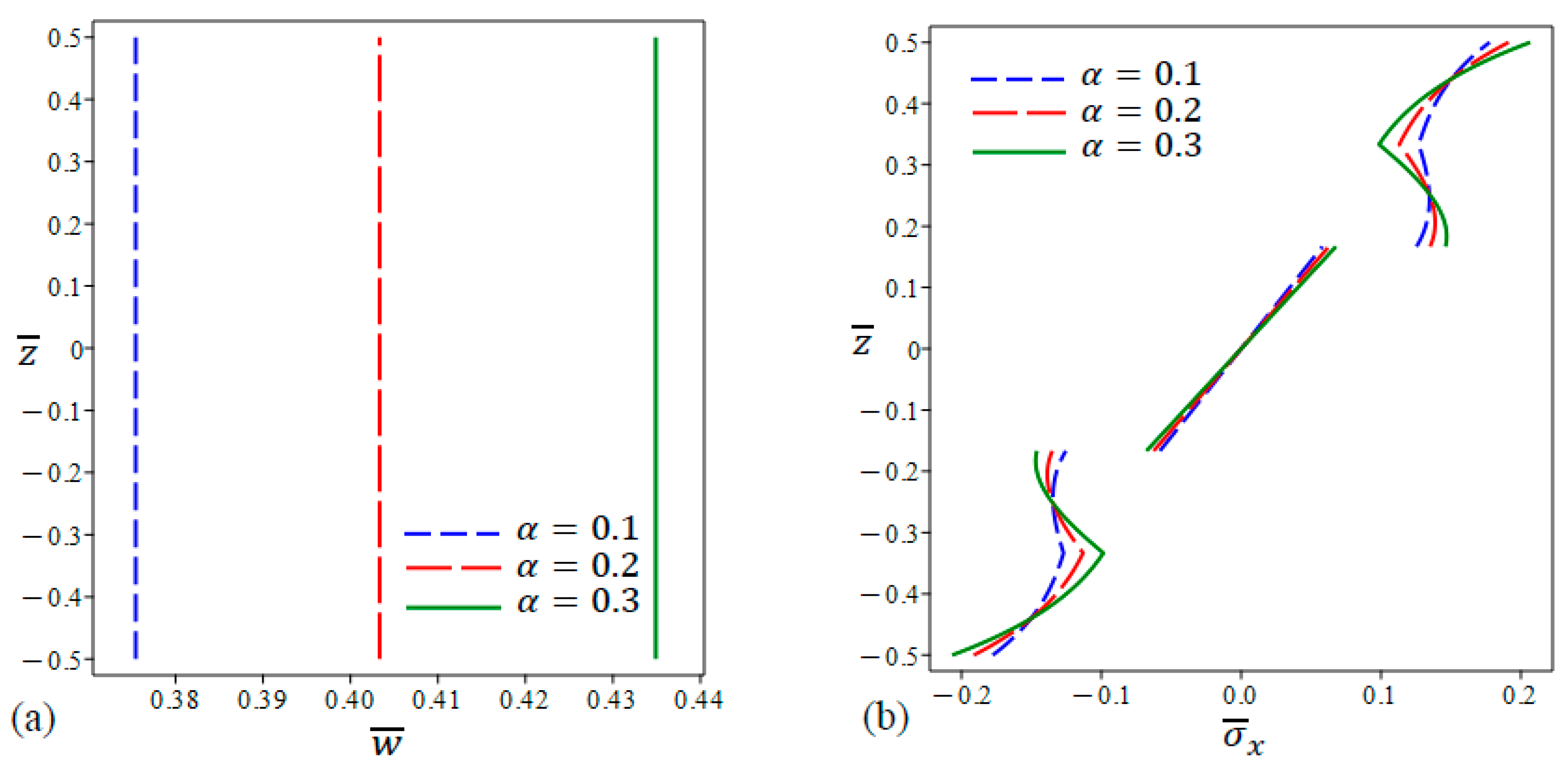
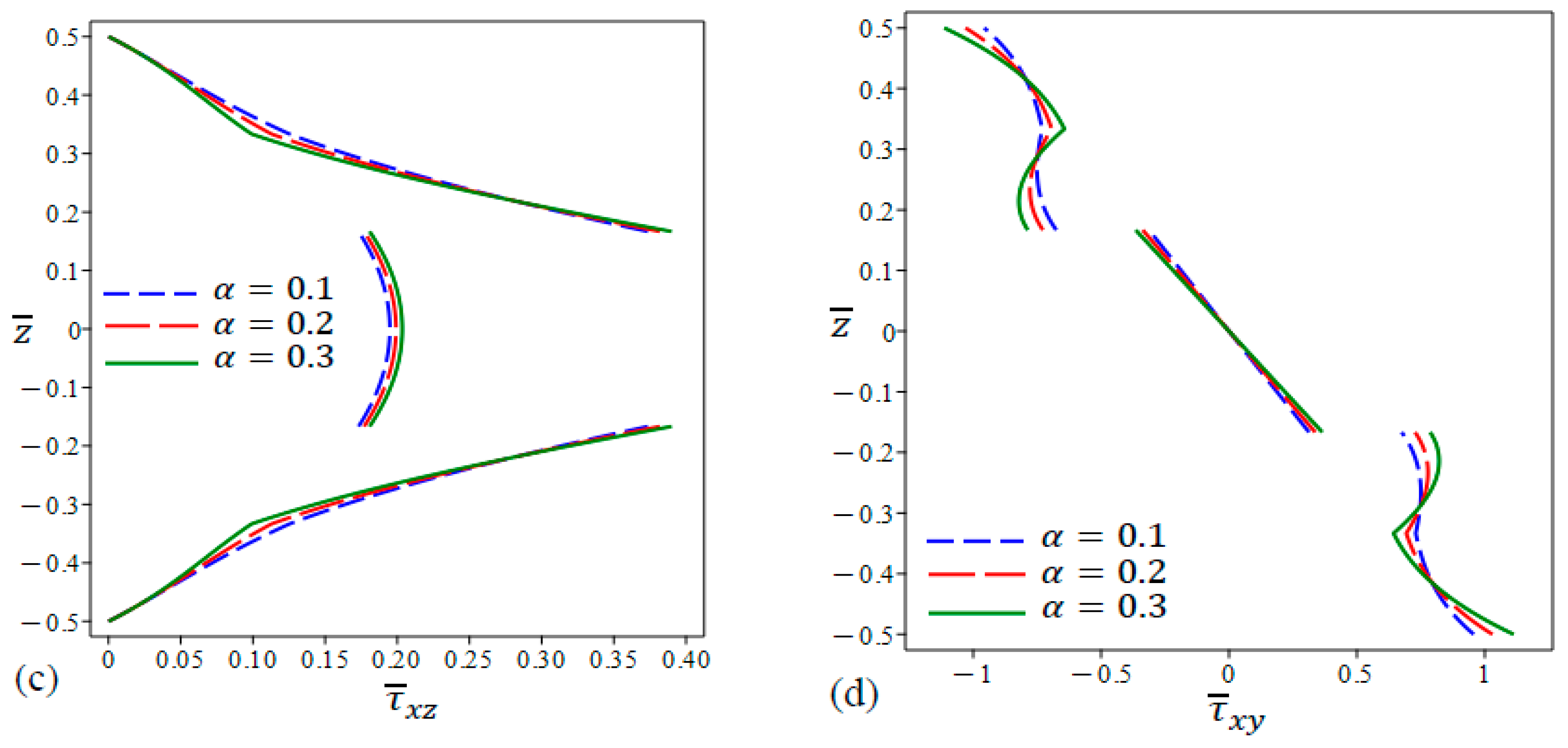
5.4.2. Sandwich Plates with Metal Core

The variation in nondimensional central deflection and nondimensional stresses across the thickness for Model B is shown in Figure 13 with the core layer made of metal instead of ceramic. The deflection in Figure 13a increases linearly with the porosity coefficient α . The increase in the deflection is due to the reduction in the modulus of elasticity of as a consequence of increasing the porosity. All types of stresses increase as α gets higher in the core layer and continue with the same trend in the external layers up to some point beyond which the trend flips twice across the external layers. As for the shear stress τ ¯ x z , the stress values at different porosity coefficient values α converge to a single point at the external surfaces of the plate. Moreover, for sandwich plates with a metal core, the variation across the thickness of axial stress and transverse shear stress show a large jump at the interfaces and also severe discontinuity.

6. Conclusions

The present study presents a comprehensive investigation of the static bending behavior of functionally graded sandwich plates. These plates are composed of a homogeneous core along with two functionally graded face sheets. Two distinct cases are considered, namely even and uneven porosity distribution across the thickness. The mechanical load applied to the plate is sinusoidally distributed. The displacement field is determined using a four-variable shear deformation theory, which has the advantage of having only four unknowns, unlike other shear deformation theories. In summary, this research highlights the following points:
  • Employing the four-variable shear deformation theory proved its soundness since it yielded similar results to those found in the literature.
  • The current findings exhibit a strong similarity to the outcomes obtained through the Third Shear Deformation Theory (TSDT).
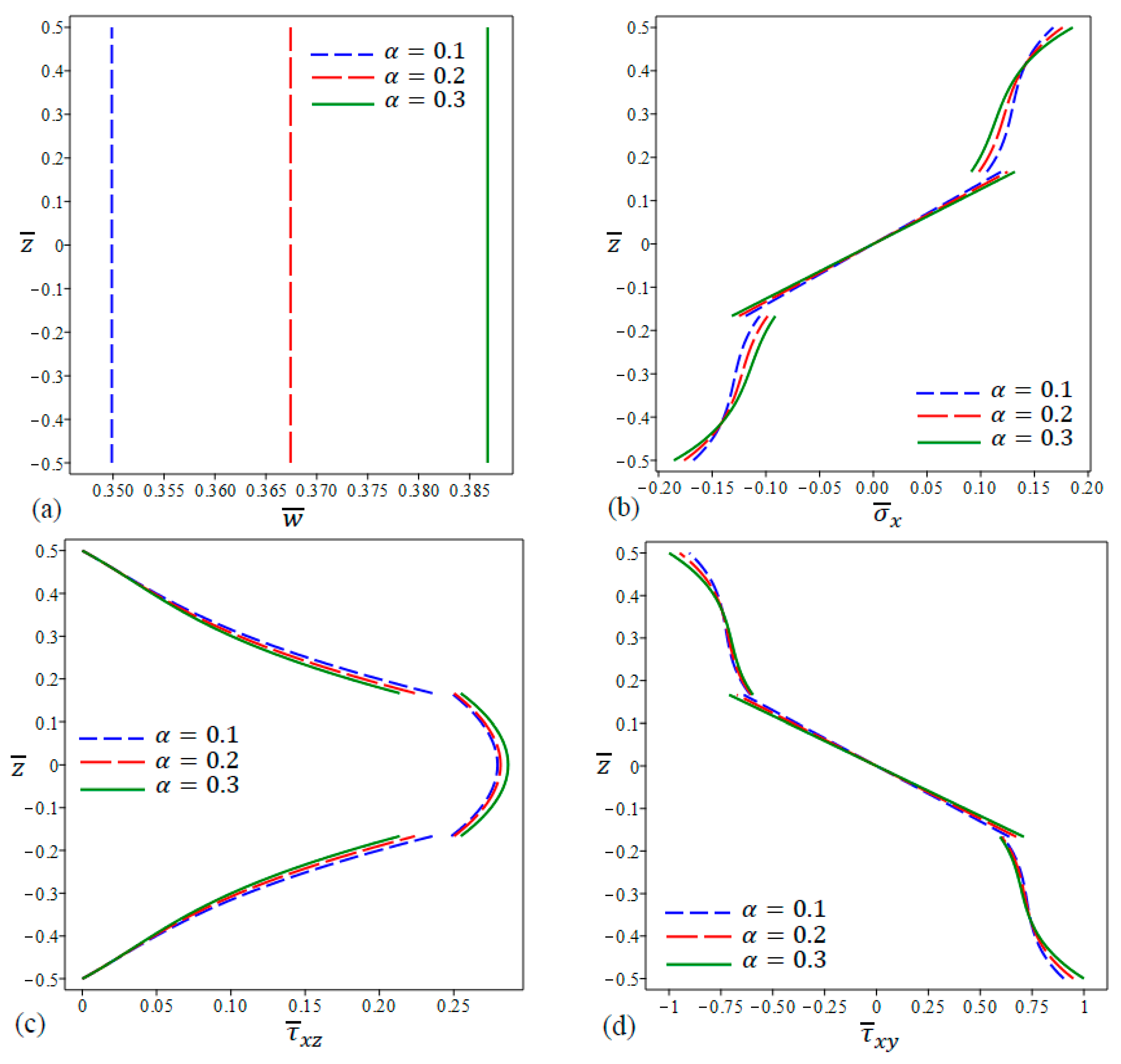
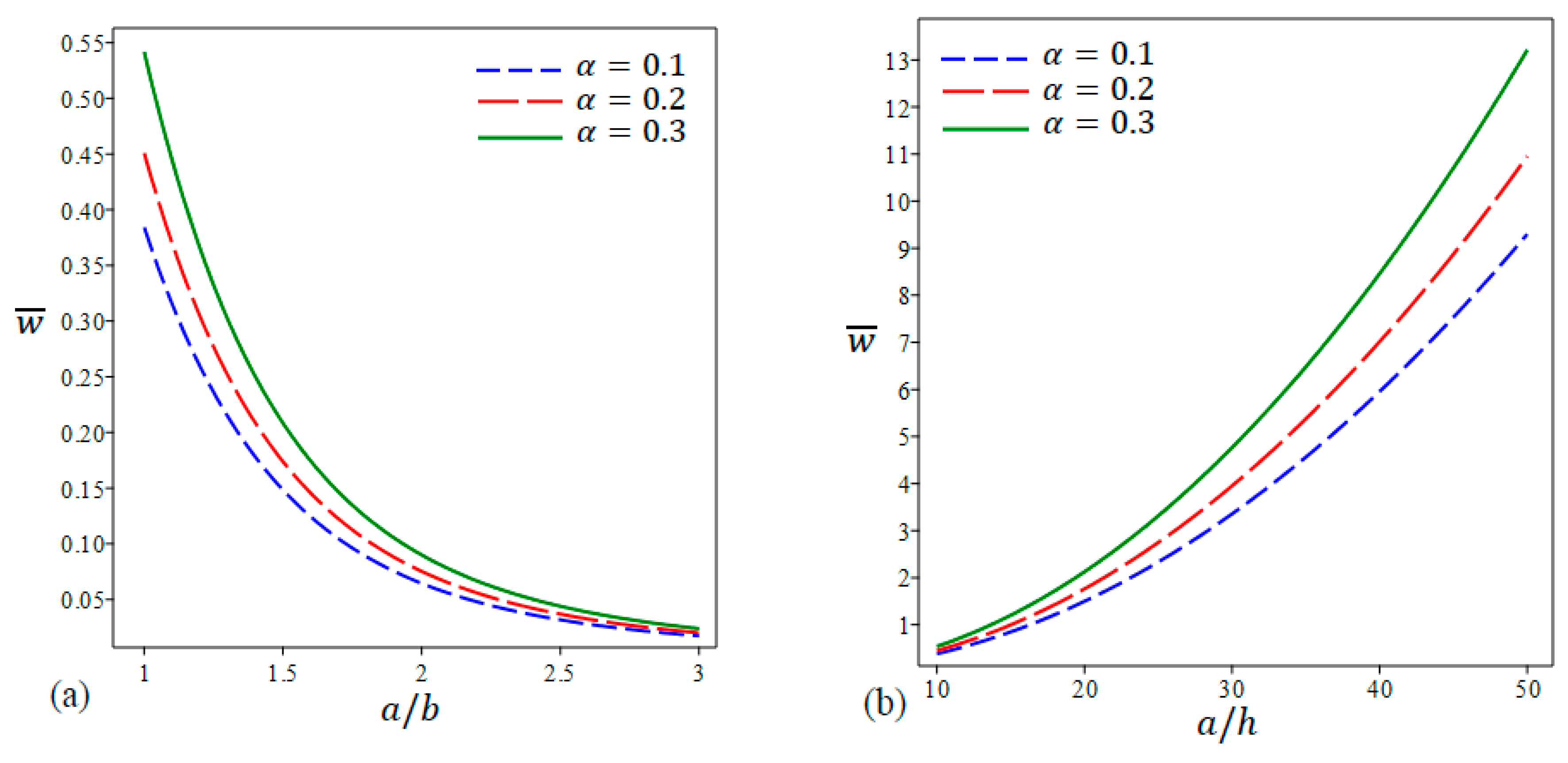
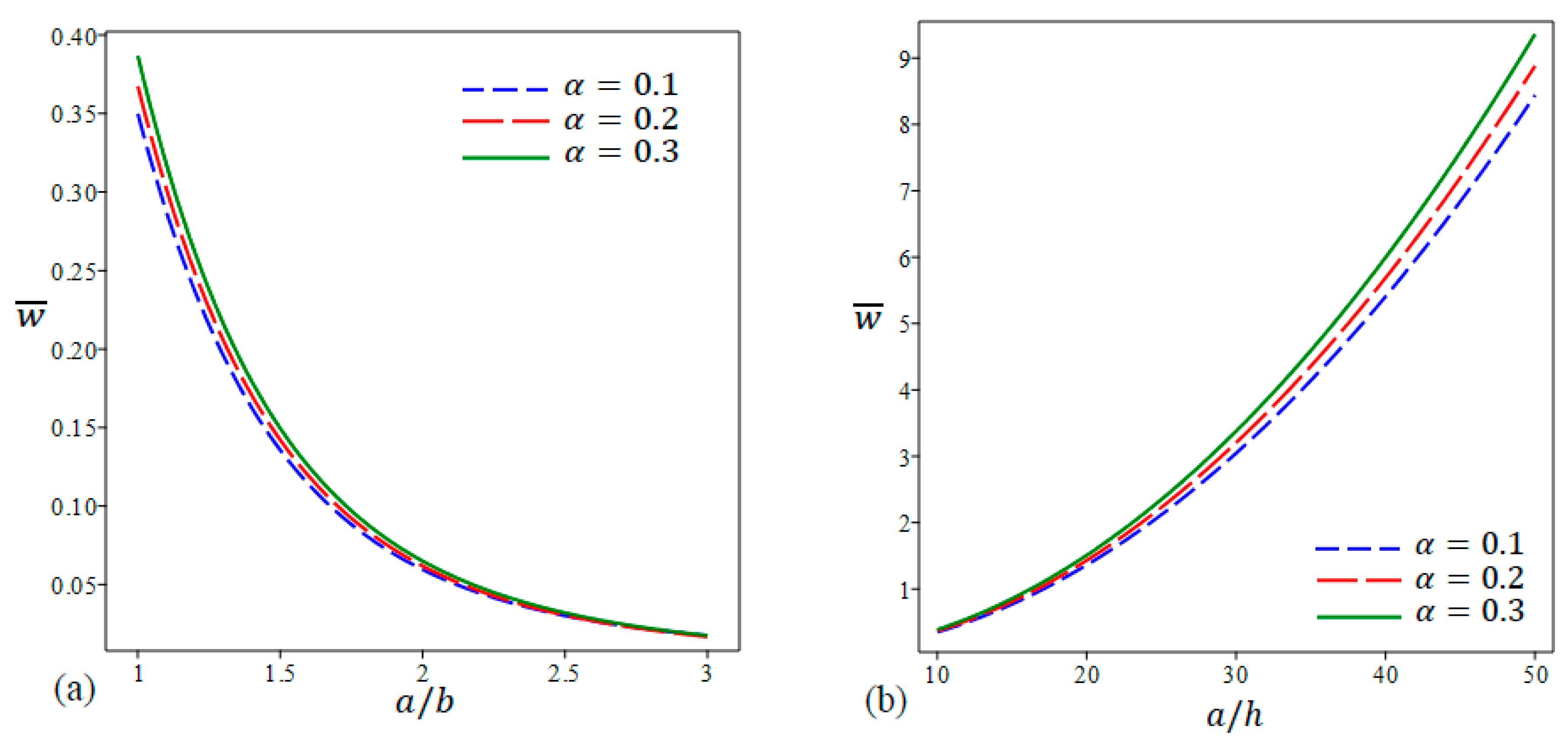
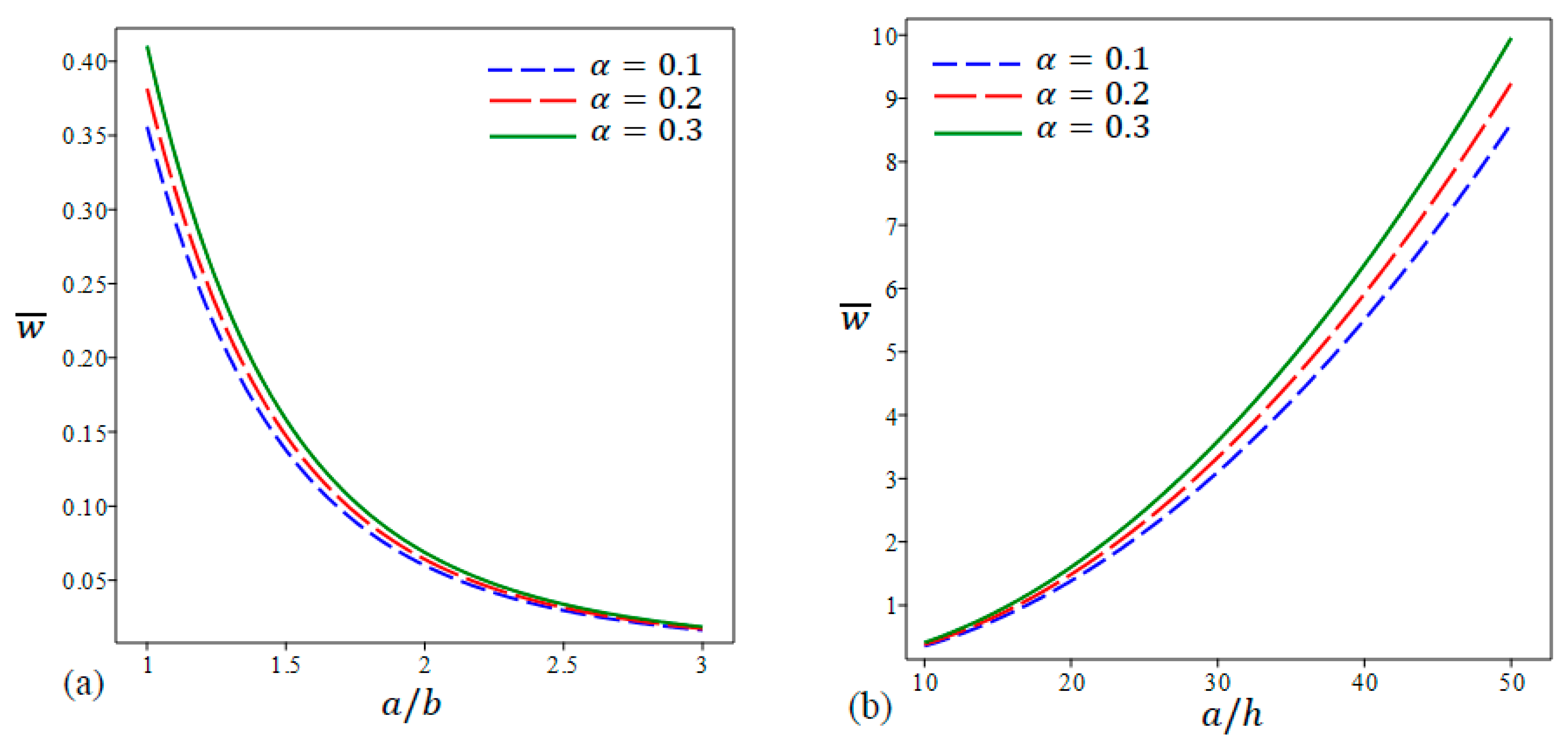
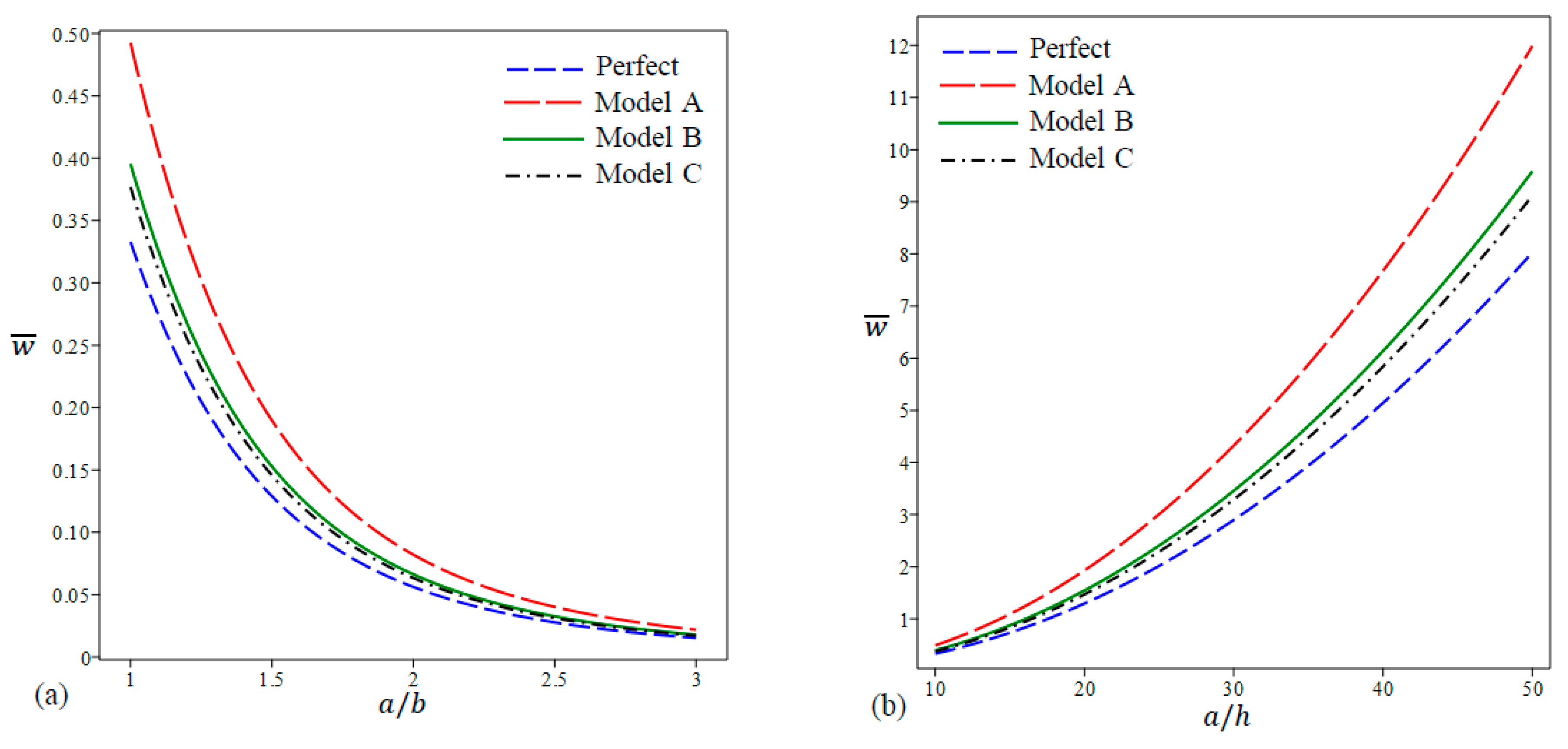
  • Higher porosity leads to larger deflections. This can be referred to as the degradation in the modulus of elasticity as a consequence of high porosities, which leads to a reduction in the bending stiffness of the plate. The central deflection is further magnified at lower aspect ratios and at higher side-to-thickness ratios due to the reduction in the plate bending stiffness in these cases.
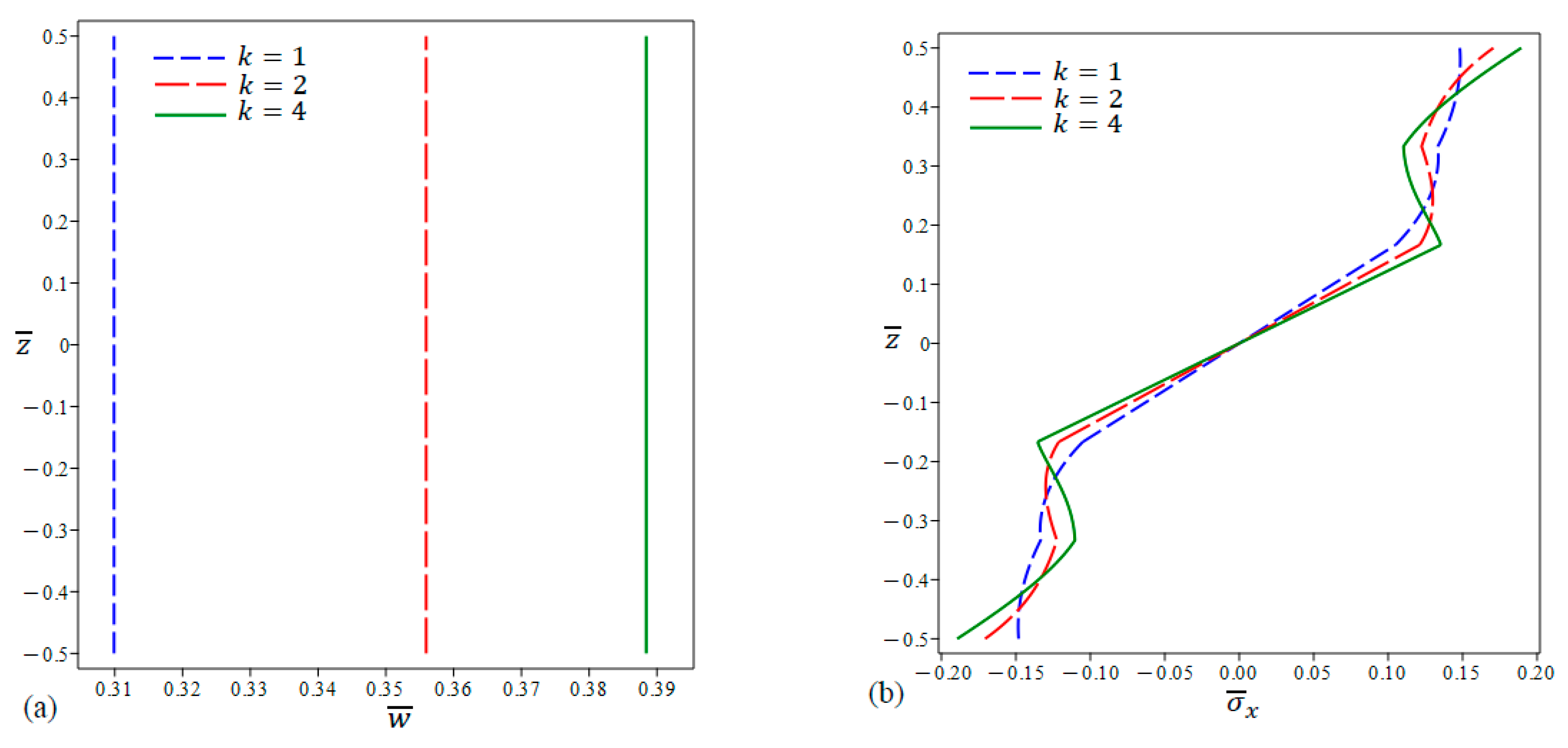
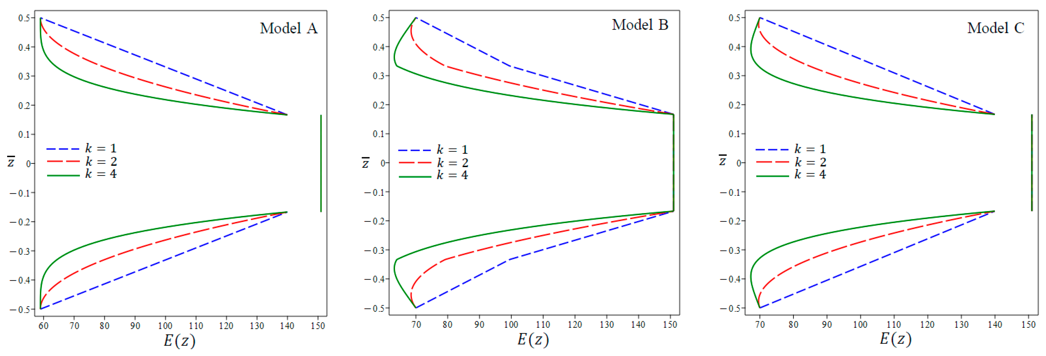
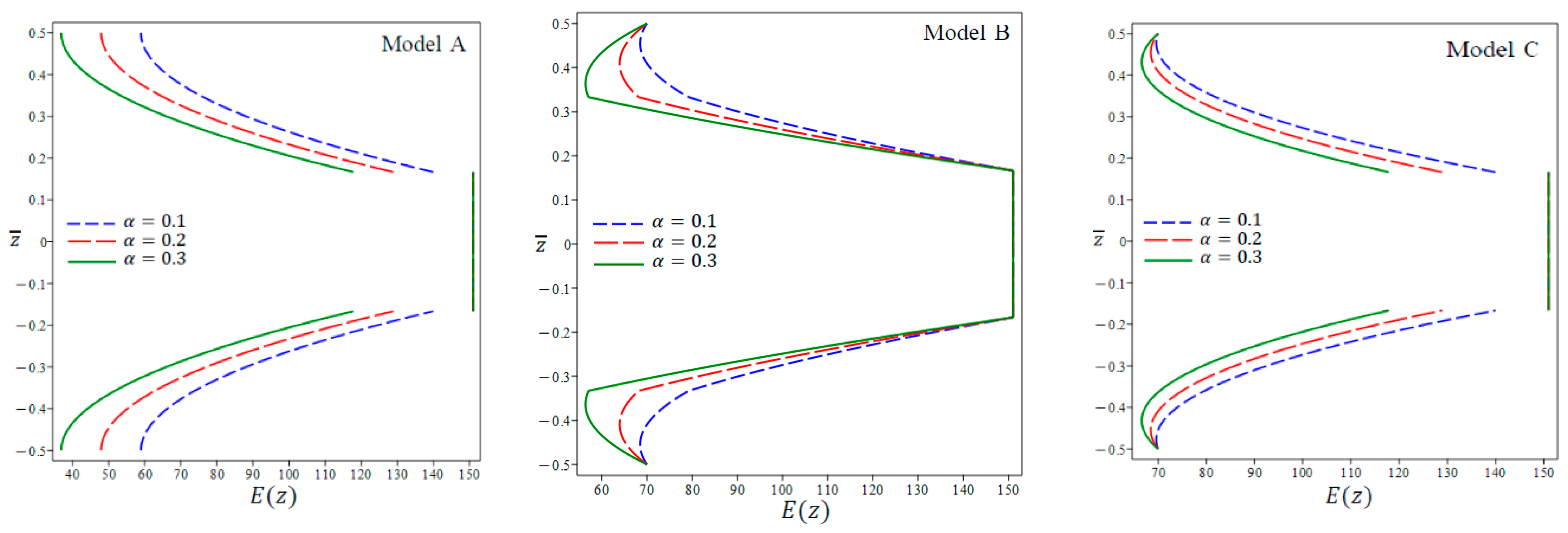
  • At the same porosity coefficient (α), the central deflection is highest in the case of Model A, lower in Model B, and lowest in Model C. This is due to the gradual reduction in the modulus of elasticity in the porosity models from Model C down to Model A. In addition, Higher values of k (defined in the volume fraction functions) result in higher central defections.
  • When the core layer in Model B is made of metal instead of ceramic, the nondimensional central deflection increases linearly with the porosity coefficient α. The increase in the deflection is due to the reduction in the modulus of elasticity of as a consequence of increasing the porosity.
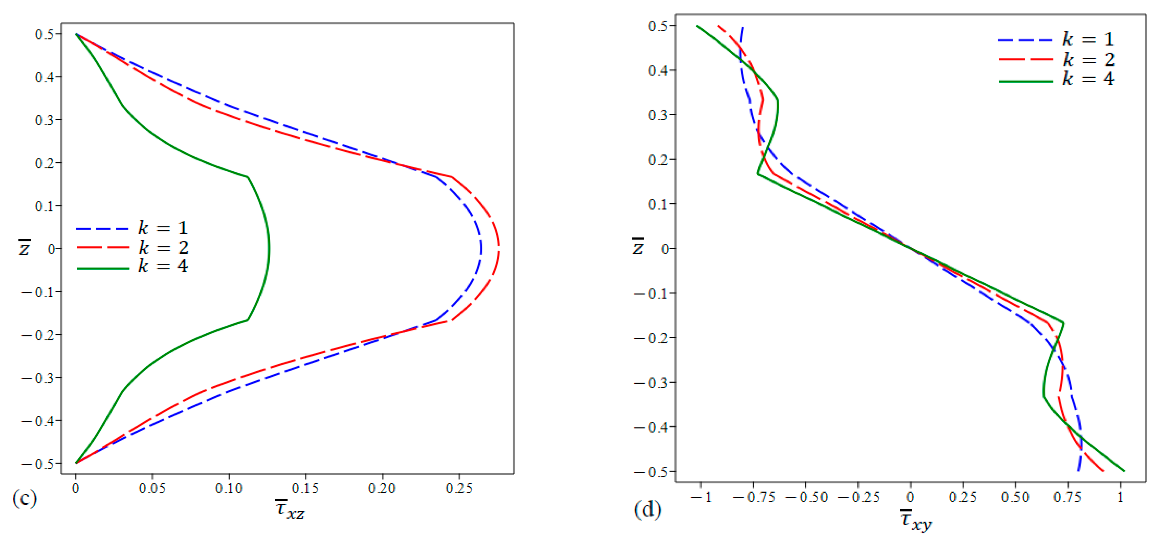
  • The stress distributions differ according to the porosity models as well as the value of the porosity coefficient. In addition, the trend exhibited in the middle homogenous layer can be maintained or reversed once or twice in the external FG layers.
  • The distributions of all stress types experience a jump at the interfaces between different layers in the case of sandwich plates with a metal core.
The findings of this research can contribute to the development of plates with advanced materials with superior mechanical properties and performance taking into consideration the porosity intensity in the constituting materials that would generate in the manufacturing phase.

Author Contributions

R.A.A.: Writing—original draft and editing, Supervision, Validation, software, Methodology, Investigation, Formal analysis, Conceptualization. R.H.A.: Writing—original draft, Validation, Methodology, Data curation. All authors have read and agreed to the published version of the manuscript.

Funding

This research received no external funding.

Data Availability Statement

No data were used for the research described in the article.

Conflicts of Interest

The authors declare no conflicts of interest.

Appendix A

a 11 = A 1 α 2 + A 24 β 2 ,   a 12 = ( A 4 + A 24 ) α β ,   a 13 = α [ A 2 α 2 + ( A 5 + 2 A 25 ) β 2 ] , a 14 = α [ A 3 α 2 + ( A 6 + 2 A 26 ) β 2 ] , a 15 = α A 7 , a 22 = A 24 α 2 + A 8 β 2 , a 23 = β [ A 9 β 2 + ( A 5 + 2 A 25 ) α 2 ] , a 24 = β [ A 10 β 2 + ( A 6 + 2 A 26 ) α 2 ] , a 25 = β A 11 , a 33 = A 12 α 4 + 2 A 14 + 2 A 27 α 2 β 2 + A 17 β 4 , a 34 = A 13 α 4 + 2 A 15 + 2 A 28 α 2 β 2 + A 18 β 4 , a 35 = A 16 α 2 + A 19 β 2 , a 44 = A 20 α 4 + A 32 α 2 + 2 A 21 + 2 A 29 α 2 β 2 + A 30 β 4 + A 22 β 4 , a 45 = ( A 22 + A 33 ) α 2 + ( A 23 + A 31 ) β 2 , a 55 = ( A 34 α 2 + A 35 β 2 + A 36 ) .

References

  1. Miyamoto, Y.; Kaysser, W.A.; Rabin, B.H.; Kawasaki, A.; Ford, R.G. Functionally Graded Materials: Design, Processing and Applications; Springer Science & Business Media: Berlin/Heidelberg, Germany, 2013; Volume 5. [Google Scholar] [CrossRef]
  2. Udupa, G.; Rao, S.S.; Gangadharan, K.V. Functionally Graded Composite Materials: An Overview. Procedia Mater. Sci. 2014, 5, 1291–1299. [Google Scholar] [CrossRef]
  3. Reddy, J.N. A General Non-linear Third Order Theory of Plates with Moderate Thickness. Int. J. Non-Linear Mech. 1990, 25, 677–686. [Google Scholar] [CrossRef]
  4. Reddy, J.N. Analysis of functionally graded plates. Int. J. Numer. Methods Eng. 2000, 47, 663–684. [Google Scholar] [CrossRef]
  5. Mantari, J.L.; Guedes Soares, C. Bending analysis of thick exponentially graded plates using a new trigonometric higher order shear deformation theory. Compos. Struct. 2012, 94, 1991–2000. [Google Scholar] [CrossRef]
  6. Zenkour, A.M.; Alghanmi, R.A. Bending of functionally graded plates via a refined quasi-3D shear and normal deformation theory. Curved Layer. Struct. 2018, 5, 190–200. [Google Scholar] [CrossRef]
  7. Liu, H.; Zhang, Q.; Ma, J. Thermo-mechanical dynamics of two-dimensional FG microbeam subjected to a moving harmonic load. Acta Astronaut. 2021, 178, 681–692. [Google Scholar] [CrossRef]
  8. Thinh, T.I.; Tu, T.M.; Quoc, T.H.; Long, N.V. Vibration and buckling analysis of functionally graded plates using new eight-unknown higher order shear deformation theory. Lat. Am. J. Solids Struct. 2016, 13, 456–477. [Google Scholar] [CrossRef]
  9. Van, T.D.; Van, V.P.; Hoang, N.N. On the development of refined plate theory for static bending behavior of functionally graded plates. Math. Probl. Eng. 2020, 2020, 2836763. [Google Scholar] [CrossRef]
  10. Madan, R.; Bhowmick, S. Modeling of functionally graded materials to estimate effective thermomechanical properties. World J. Eng. 2021, 19, 291–301. [Google Scholar] [CrossRef]
  11. Abdalla, H.; Casagrande, D. An intrinsic material tailoring approach for functionally graded ax-isymmetric hollow bodies under plane elasticity. J. Elast. 2021, 144, 15–32. [Google Scholar] [CrossRef]
  12. Eldeeb, A.; Shabana, Y.; Elsawaf, A. Influences of angular deceleration on the thermoelastoplastic behaviors of nonuniform thickness multilayer FGM discs. Compos. Struct. 2021, 258, 113092. [Google Scholar] [CrossRef]
  13. Eldeeb, A.; Shabana, Y.; Elsawaf, A. Thermo-elastoplastic behavior of a rotating sandwich disc made of temperature-dependent functionally graded materials. J. Sandw. Struct. Mater. 2021, 23, 1761–1783. [Google Scholar] [CrossRef]
  14. Zenkour, A.M. A comprehensive analysis of functionally graded sandwich plates: Part 1—Deflection and stresses. Int. J. Solids Struct. 2005, 42, 5224–5242. [Google Scholar] [CrossRef]
  15. Zenkour, A.M. A comprehensive analysis of functionally graded sandwich plates: Part 2—Buckling and free vibration. Int. J. Solids Struct. 2005, 42, 5243–5258. [Google Scholar] [CrossRef]
  16. Thai, H.T.; Nguyen, T.K.; Vo, T.P.; Lee, J. Analysis of functionally graded sandwich plates using a new first-order shear deformation theory. Eur. J. Mech.-A/Solids 2014, 45, 211–225. [Google Scholar] [CrossRef]
  17. Nguyen, T.K.; Nguyen, V.H.; Chau-Dinh, T.; Vo, T.P.; Nguyen-Xuan, H. Static and vibration analysis of isotropic and functionally graded sandwich plates using an edge-based MITC3 finite elements. Compos. Part B-Eng. 2016, 107, 162–173. [Google Scholar] [CrossRef]
  18. Mantari, J.; Granados, E. A Refined FSDT for the Static Analysis of Functionally Graded Sandwich Plates. Thin-Walled Struct. 2015, 90, 150–158. [Google Scholar] [CrossRef]
  19. Naghavi, M.; Sarrami-Foroushani, S.; Azhari, F. Bending Analysis of Functionally Graded Sandwich Plates Using the Refined Finite Strip Method. J. Sandw. Struct. Mater. 2022, 24, 448–483. [Google Scholar] [CrossRef]
  20. Hirane, H.; Belarbi, M.O.; Houari, M.S.A.; Tounsi, A. On the Layerwise Finite Element Formulation for Static and Free Vibration Analysis of Functionally Graded Sandwich Plates. Eng. Comput. 2021, 38, 3871–3899. [Google Scholar] [CrossRef]
  21. Cho, J.R. Free Vibration Analysis of Functionally Graded Sandwich Plates with a Homogeneous Core. Appl. Sci. 2022, 12, 6054. [Google Scholar] [CrossRef]
  22. Monajati, L.; Farid, N.; Farid, M.; Parandvar, H. Vibration and buckling analyses of functionally graded plates based on refined plate theory using airy stress function. Proc. Inst. Mech. Eng. Part C 2022, 236, 8231–8244. [Google Scholar] [CrossRef]
  23. Zhu, J.; Lai, Z.; Yin, Z.; Jeon, J.; Lee, S. Fabrication of ZrO2–NiCr Functionally Graded Material by Powder Metallurgy. Mater. Chem. Phys. 2001, 68, 130–135. [Google Scholar] [CrossRef]
  24. Jabbari, M.; Mojahedin, A.; Haghi, M. Buckling Analysis of Thin Circular FG Plates Made of Saturated Porous-Soft Ferromagnetic Materials in Transverse Magnetic Field. Thin-Walled Struct. 2014, 85, 50–56. [Google Scholar] [CrossRef]
  25. Ebrahimi, F.; Jafari, A. Buckling Behavior of Smart MEE-FG Porous Plate with Various Boundary Conditions Based on Refined Theory. Adv. Mater. Res. 2016, 5, 279–298. [Google Scholar] [CrossRef]
  26. Feyzi, M.R.; Khorshidvand, A.R. Axisymmetric Post-Buckling Behavior of Saturated Porous Circular Plates. Thin-Walled Struct. 2017, 112, 149–158. [Google Scholar] [CrossRef]
  27. Rezaei, A.S.; Saidi, A.R. Buckling Response of Moderately Thick Fluid-Infiltrated Porous Annular Sector Plates. Acta Mech. 2017, 228, 3929–3945. [Google Scholar] [CrossRef]
  28. Liu, Y.; Suab, S.; Huang, H.; Liang, Y. Thermal-Mechanical Coupling Buckling Analysis of Porous Functionally Graded Sandwich Beams Based on Physical Neutral Plane. Part B-Eng. 2019, 168, 236–242. [Google Scholar] [CrossRef]
  29. Wattanasakulpong, N.; Prusty, B.G.; Kelly, D.; Hoffman, M. Free Vibration Analysis of Layered Functionally Graded Beams with Experimental Validation. Mater. Des. (1980–2015) 2012, 36, 182–190. [Google Scholar] [CrossRef]
  30. Chen, D.; Yang, J.; Kitipornchai, S. Free and Forced Vibrations of Shear Deformable Functionally Graded Porous Beams. Int. J. Mech. Sci. 2016, 108–109, 14–22. [Google Scholar] [CrossRef]
  31. Ghadiri, M.; SafarPour, H. Free Vibration Analysis of Size-dependent Functionally Graded Porous Cylindrical Microshells in Thermal Environment. J. Therm. Stress. 2016, 40, 55–71. [Google Scholar] [CrossRef]
  32. Shafiei, N.; Mirjavadi, S.S.; MohaselAfshari, B.; Rabby, S.; Kazemi, M. Vibration of Two-dimensional Imperfect Functionally Graded (2D-FG) Porous Nano-/Micro-Beams. Methods Appl. Mech. Eng. 2017, 322, 615–632. [Google Scholar] [CrossRef]
  33. Arshid, E.; Khorshidvand, A.R. Free Vibration Analysis of Saturated Porous FG Circular Plates Integrated with Piezoelectric Actuators via Differential Quadrature Method. Thin-Walled Struct. 2018, 125, 220–233. [Google Scholar] [CrossRef]
  34. Akbas, S. Forced Vibration Analysis of Functionally Graded Porous Deep Beams. Compos. Struct. 2018, 186, 293–302. [Google Scholar] [CrossRef]
  35. Wu, D.; Liu, A.; Huang, Y.; Pi, Y.; Gao, W. Dynamic Analysis of Functionally Graded Porous Structures through Finite Element Analysis. Eng. Struct. 2018, 165, 287–301. [Google Scholar] [CrossRef]
  36. Gao, K.; Li, R.; Yang, J. Dynamic Characteristics of Functionally Graded Porous Beams with Interval Material Properties. Eng. Struct. 2019, 197, 109441. [Google Scholar] [CrossRef]
  37. Zenkour, A.M.; Radwan, A.F. Bending Response of FG Plates Resting on Elastic Foundations in Hygrothermal Environment with Porosities. Compos. Struct. 2019, 213, 133–143. [Google Scholar] [CrossRef]
  38. Alghanmi, R.A.; Zenkour, A.M. An Electromechanical Model for Functionally Graded Porous Plates Attached to Piezoelectric Layer Based on Hyperbolic Shear and Normal Deformation Theory. Compos. Struct. 2021, 274, 114352. [Google Scholar] [CrossRef]
  39. Alghanmi, R.A.; Zenkour, A.M. Effect of Porosity on the Bending of Functionally Graded Plates Integrated with PFRC Layer. Eur. Phys. J. Plus 2021, 136, 142. [Google Scholar] [CrossRef]
  40. Benferhat, R.; Daouadji, T.H.; Abderezak, R. Effect of Porosity on Fundamental Frequencies of FGM Sandwich Plates. Materials 2021, 13, 25. [Google Scholar]
  41. Vinh, P.V.; Huy, L.Q. Finite Element Analysis of Functionally Graded Sandwich Plates with Porosity via a New Hyperbolic Shear Deformation Theory. Def. Technol. 2022, 18, 490–508. [Google Scholar] [CrossRef]
  42. Dastjerdi, S.; Malikan, M.; Dimitri, R.; Tornabene, F. Nonlocal Elasticity Analysis of Moderately Thick Porous Functionally Graded Plates in a Hygro-Thermal Environment. Compos. Struct. 2021, 255, 112925. [Google Scholar] [CrossRef]
  43. Alghanmi, R.A. Nonlocal Strain Gradient Theory for the Bending of Functionally Graded Porous Nanoplates. Materials 2022, 15, 8601. [Google Scholar] [CrossRef] [PubMed]
  44. Zenkour, A.M.; Alghanmi, R.A. Hygro-Thermo-Electro-Mechanical Bending Analysis of Sandwich Plates with FG Core and Piezoelectric Faces. Mech. Adv. Mater. Struct. 2021, 28, 282–294. [Google Scholar] [CrossRef]
  45. Mota, A.F.; Loja, M.A.R.; Barbosa, J.I.; Rodrigues, J.A. Porous Functionally Graded Plates: An Assessment of the Influence of Shear Correction Factor on Static Behavior. Math. Comput. Appl. 2020, 25, 25. [Google Scholar] [CrossRef]
  46. Zenkour, A.M.; Aljadani, M.H. Buckling Response of Functionally Graded Porous Plates Due to a Quasi-3D Refined Theory. Mathematics 2022, 10, 565. [Google Scholar] [CrossRef]
  47. Dhuria, M.; Grover, N.; Goyal, K. Influence of Porosity Distribution on Static and Buckling Responses of Porous Functionally Graded Plates. Structures 2021, 34, 1458–1474. [Google Scholar] [CrossRef]
  48. Alghanmi, R. Hygrothermal Bending Analysis of Sandwich Nanoplates with FG Porous Core and Piezomagnetic Faces via Nonlocal Strain Gradient Theory. Nanotechnol. Rev. 2023, 12, 20230123. [Google Scholar] [CrossRef]
  49. Quan, T.Q.; Ha, D.T.T.; Duc, N.D. Analytical Solutions for Nonlinear Vibration of Porous Functionally Graded Sandwich Plate Subjected to Blast Loading. Thin-Walled Struct. 2022, 170, 108606. [Google Scholar] [CrossRef]
  50. Shimpi, R.P.; Patel, H.G. A Two Variable Refined Plate Theory for Orthotropic Plate Analysis. Int. J. Solids Struct. 2006, 43, 6783–6799. [Google Scholar] [CrossRef]
  51. Thai, H.T.; Kim, S.E. Analytical Solution of a Two Variable Refined Plate Theory for Bending Analysis of Orthotropic Levy-Type Plates. Int. J. Mech. Sci. 2012, 54, 269–276. [Google Scholar] [CrossRef]
Figure 1. Geometry and dimensions of the sandwich plate with porosities.
Mca 29 00020 g001
Figure 2. Variation in Young’s modulus of porous FG sandwich plate for different values of k ( α = 0.1 ) .
Mca 29 00020 g002
Figure 3. Variation in Young’s modulus of porous FG sandwich plate for different porosity factor α ( k = 2 ) .
Mca 29 00020 g003
Figure 4. The distribution of nondimensional center deflection and stresses in a square FG sandwich plate (Model A) for different porosity factor α ( k = 2). (a) w ¯ , (b) σ ¯ x , (c) τ ¯ x z , (d) τ ¯ x y .
Mca 29 00020 g004
Figure 5. The distribution of nondimensional center deflection and stresses in a square FG sandwich plate (Model B) for different porosity factor α ( k = 2). (a) w ¯ , (b) σ ¯ x , (c) τ ¯ x z , (d) τ ¯ x y .
Mca 29 00020 g005aMca 29 00020 g005b
Figure 6. The distribution of nondimensional center deflection and stresses in a square FG sandwich plate (Model C) for different porosity factor α ( k = 2). (a) w ¯ , (b) σ ¯ x , (c) τ ¯ x z , (d) τ ¯ x y .
Mca 29 00020 g006
Figure 7. The distribution of nondimensional center deflection in a square FG sandwich plate ( k = 2) (Model A) as a function of the following: (a) aspect ratio a / b ; (b) side-to-thickness ratio a / h .
Mca 29 00020 g007
Figure 8. The distribution of nondimensional center deflection in a square FG sandwich plate (Model B) as a function of the following: (a) aspect ratio a / b ; (b) side-to-thickness ratio a / h .
Mca 29 00020 g008
Figure 9. The distribution of nondimensional center deflection in a square FG sandwich plate ( k = 2) (Model C) as a function of the following: (a) aspect ratio a/b; (b) side-to-thickness ratio a/h.
Mca 29 00020 g009
Figure 10. The distribution of nondimensional center deflection and stresses in a square FG sandwich plate for different porosity models ( k = 2) ( α = 0.25). (a) w ¯ , (b) σ ¯ x , (c) τ ¯ x z , (d) τ ¯ x y .
Mca 29 00020 g010
Figure 11. The distribution of nondimensional center deflection in a square FG sandwich plate for different porosity models as a function of the following: (a) aspect ratio a / b ; (b) side-to-thickness ratio a / h ( α = 0.25 ,   k = 2 ).
Mca 29 00020 g011
Figure 12. The distribution of nondimensional center deflection and stresses in a square FG sandwich plate with ceramic core (Model B) for different values of k ( α = 0.1). (a) w ¯ , (b) σ ¯ x , (c) τ ¯ x z , (d) τ ¯ x y .
Mca 29 00020 g012aMca 29 00020 g012b
Figure 13. The distribution of nondimensional center deflection and stresses in a square FG sandwich plate with metal core (Model B) for different porosity factor α ( k = 2). (a) w ¯ , (b) σ ¯ x , (c) τ ¯ x z , (d) τ ¯ x y .
Mca 29 00020 g013aMca 29 00020 g013b
Table 1. Dimensionless central deflection w ¯ of non-porous FG sandwich plates (perfect FG) ( k = 2).
SchemeMethod a / b
1 / 3 0.5 1 1.5 2
1-0-1CPT [14]1.162470.918650.358850.135900.05742
FSDT [14]1.192000.944730.375140.145920.06393
SSDT [14]1.188080.941240.372970.144580.06305
TSDT [14]1.188770.941860.373350.144810.06321
Present1.188770.941860.373350.144810.06321
2-1-2CPT [14]1.099710.868910.339420.128540.05431
FSDT [14]1.126110.892370.354080.137560.06017
SSDT [14]1.122040.888760.351830.136170.05926
TSDT [14]1.122930.889550.352310.136470.05946
Present1.122930.889450.352310.136470.05946
1-1-1CPT [14]1.038950.820900.320670.121440.05131
FSDT [14]1.063690.842890.334110.129890.05680
SSDT [14]1.059890.839520.332300.128950.05619
TSDT [14]1.060960.840460.332890.128950.05619
Present1.060960.840460.332890.128950.05619
2-2-1CPT [14]0.985120.778370.304050.115140.04085
FSDT [14]1.009110.799690.317380.123340.05398
SSDT [14]1.005850.796790.345570.122220.05325
TSDT [14]1.006940.797760.316170.122600.05325
Present1.006940.797760.316170.122600.05349
1-2-1CPT [14]0.942690.744890.290950.110180.04655
FSDT [14]0.965630.765240.303700.108030.05165
SSDT [14]0.962480.762430.301950.116940.05094
TSDT [14]0.963710.763530.302630.117370.05122
Present0.963710.763530.302630.117370.05122
Table 2. Effect of porosities on dimensionless central deflection w ¯ ( 0 ) of FG sandwich plates with ceramic core ( k = 2).
a / h α PerfectModel AModel BModel C
1000.33289------
0.1--0.384140.355950.34794
0.2--0.450860.381550.36742
0.3--0.541840.410390.38677
2001.29489------
0.1--1.498561.386531.36044
0.2--1.763821.488591.43190
0.3--2.125771.603411.50869
5008.02885------
0.1--9.299428.600678.44051
0.2--10.954499.237798.88325
0.3--13.213229.954539.36211
Table 3. Effect of porosities on dimensionless normal stress σ ¯ x h / 2 of FG sandwich plates with ceramic core ( k = 2).
a / h α PerfectModel AModel BModel C
1001.59370------
0.1--0.148100.170690.16741
0.2--0.136920.183250.17624
0.3--0.122180.197410.18569
2001.58524------
0.1--0.148270.169820.16666
0.2--0.136320.182390.17538
0.3--0.121690.196540.18483
5001.58287------
0.1--0.148070.169570.16641
0.2--0.136150.182150.17515
0.3--0.121560.196290.18459
Table 4. Effect of porosities on dimensionless shear stress τ ¯ x z 0 of FG sandwich plates with ceramic core ( k = 2).
a / h α PerfectModel AModel BModel C
1000.27188------
0.1--0.280650.275410.23777
0.2--0.290740.279150.28146
0.3--0.302600.283130.28661
2000.27197------
0.1--0.280740.275070.26221
0.2--0.290830.279250.28155
0.3--0.302670.283230.28671
5000.27200------
0.1--0.280770.274980.26998
0.2--0.290850.279280.28158
0.3--0.302700.283260.28674
Table 5. Effect of porosities on shear stress τ ¯ x y h / 3 of FG sandwich plates with ceramic core ( k = 2).
a / h α PerfectModel AModel BModel C
1000.73130------
0.1--0.761240.703890.73064
0.2--0.790660.666320.72685
0.3--0.819270.616600.72113
2001.46421------
0.1--1.523801.409151.46221
0.2--1.582311.333971.45539
0.3--1.639151.234381.44396
5003.66166------
0.1--3.810423.523823.65625
0.2--3.956463.335863.63964
0.3--4.098303.086763.61108
Disclaimer/Publisher’s Note: The statements, opinions and data contained in all publications are solely those of the individual author(s) and contributor(s) and not of MDPI and/or the editor(s). MDPI and/or the editor(s) disclaim responsibility for any injury to people or property resulting from any ideas, methods, instructions or products referred to in the content.

