Article

Al2O3/GeO2/P2O5/F-Doped Silica Large-Mode-Area Optical Fibers for High-Power Single-Frequency Radiation Delivery

1
Prokhorov General Physics Institute of the Russian Academy of Sciences, Dianov Fiber Optics Research Center, 119333 Moscow, Russia
2
G.G. Devyatykh Institute of Chemistry of High-Purity Substances, Russian Academy of Sciences, 49 Tropinin St., 603951 Nizhny Novgorod, Russia
3
James C. Wyant College of Optical Sciences, University of Arizona, 1630 E. University Blvd, Tucson, AZ 85721-0094, USA
*
Author to whom correspondence should be addressed.
Photonics 2023, 10(10), 1150; https://doi.org/10.3390/photonics10101150
Submission received: 29 September 2023 / Revised: 10 October 2023 / Accepted: 11 October 2023 / Published: 13 October 2023
(This article belongs to the Special Issue Optical Fiber Lasers)

Abstract

:
A new design of a passive optical fiber waveguide with a large mode area (LMA) and strong stimulated Brillouin scattering (SBS) suppression is proposed. The fiber core consists of two parts: a central one, doped with Al2O3 and GeO2, and a peripheral one, doped with P2O5 and F. The doping profiles form a gradient-increasing profile of the acoustic refractive index, which effectively implements the acoustic multimode SBS suppression method. Measurements of the SBS gain spectrum and SBS threshold power were carried out, showing an increase in the SBS threshold of no less than 11 dB compared to a conventional uniformly doped passive LMA fiber.

1. Introduction

In recent years, high-peak-power (kW or more) single-mode narrow-band (<10 MHz) pulsed all-fiber optical amplifiers have undergone great development [1,2,3]. Large-mode-area (LMA) fibers are the key elements of such devices allowing the thresholds of nonlinear effects to be sufficiently raised, the first of which is stimulated Brillouin scattering (SBS). Such amplifiers can provide a power of more than 4 kW at 1550 nm wavelength with a good beam quality [2]. However, further delivery of radiation from the amplifier usually faces a problem of a relatively low threshold of SBS in passive fibers used for this purpose. For active optical fibers, there are much more ways to increase the SBS power threshold rather than for passive ones. In particular, active single-mode fibers can be realized with longitudinal variations in the core diameter (e.g., tapers) [4], with an acousto-optically dense pedestal structure surrounding the fiber core [5], with different sorts of strain distribution [6,7], a thermal gradient over a fiber length [8], etc. For passive fibers, especially when used as “pigtails” for single-mode radiation, all these methods are inapplicable. The typical solution is to reduce the fiber length as much as possible, which obviously has its limits.
However, there is an alternative way to significantly raise the SBS power threshold in a passive optical fiber while preserving its optical properties—the modification of the acoustical refractive index profile (ARIP) [9,10,11], achieved through a specific choice of dopants in the core area and their quantity. In this case, it becomes possible to maintain the uniformity of the optical properties of the fiber along its length, which is critical for passive radiation transmission. From the point of view of the SBS process, the fiber is an acousto-optical waveguide in which a part of the optical radiation energy is coupled with the reflected Stokes wave via a spectrum of acoustic modes excited in accordance with both the spatial symmetry of the optical mode field and the structure of the ARIP [12]. With homogeneous doping of the fiber core, Brillouin acousto-optical interaction occurs mainly due to the preferential excitation of one acoustic mode of the lowest order, which causes the relatively small width of the acoustic frequency band (~40 MHz) within which this interaction occurs, as well as a high degree of coherence of this interaction, which leads to the high SBS gain. The ARIP modification allows not only a shift in the central acoustic frequency of the Brillouin interaction but also a significant change in the spatial overlap of the fields of acoustic modes and the intensity of the optical field. In connection with the latter, until recently, the main effort was put into trying to create an “anti-guide” ARIP, which is supposed to minimize the excitation of guided modes of the acoustic waveguide. However, since in such an acoustic waveguide the so-called “leaky” acoustic modes [13,14]—which do not have a sufficiently high radiation loss coefficient, but good spatial overlap with the optical field—are effectively excited, in practice, the degree of suppression of the SBS gain was no more than 5–6 dB (although there are theoretically predicted values of up to 14 dB [15]).
In 2021, a method for multimode acoustic SBS gain suppression was proposed in [16]. It uses the fact that, when modifying step-index ARIP, both the spatial distributions of the fields of acoustic modes and their eigen-frequencies change. Due to the complex doping of the core material with various dopants (e.g., P2O5, F, GeO2), this allows for a given optical refractive index profile (ORIP) to create such an ARIP structure where most of the acoustic modes with the corresponding azimuthal field symmetry will have the same overlap integrals with the optical intensity field, and thus will have equal excitation efficiency. As a result, the acoustic spectrum of the Brillouin gain will be uniformly distributed over a relatively large range, and its maximum will be reduced to a factor proportional to the number of effectively excited acoustic modes.
Today, in high-power fiber amplifier circuits, commercially available passive LMA fibers used for delivery of radiation at 1550 nm can have core diameters of up to ~30 μm [17]. The typical numerical aperture (NA) in such fibers is ~0.065–0.09, which makes it possible to implement an effectively single-mode optical regime and maintain a relatively small critical bending radius. As shown in [16], in such fibers implemented with a P2O5/F doping composition in accordance with therecently proposed method, a degree of the SBS gain suppression greatlydepends on adherence to the optimal ARIP curvature, especially within the central part of the core, which is hard to achieve at a big core size.In addition, actual technological limitations (at least, for the modified chemical vapor deposition (MCVD) method) of simultaneous doping of silica glass with P2O5 and F [18] restrict the potential size of the frequency band (within which the acoustic modes can be effectively excited) to a value of ~600 MHz, providing a corresponding reduction in SBS gain. Previously, SBS suppression by 8 dB was demonstrated using this method [16].
In the current paper, we propose to further advance the potential of this promising method by introducing an additional Al2O3 dopant into the central part of the fiber core, which can help expand the Brillouin gain bandwidth (to ~1 GHz). A new design of a passive Al2O3/GeO2/P2O5/F-doped LMA optical fiber was investigated and tested. It is shown that this design can provide a suppression of the SBS power threshold by no less than 11 dB compared to the conventional GeO2-doped LMA fiber, which, to the best of our knowledge, is a record for this type of optical fiber.

2. Materials and Methods

2.1. Acousto-Optical Properties of the Dopants

First, let us consider the acousto-optical properties of the dopants used in our proposal. As is well known, in moderate quantities, additives such as Al2O3, GeO2, P2O5 and F can be taken into account in calculating changes in the acoustic ∆N and optical ∆n indices of silica glass in the following form:
Δ N = X R ac , X C X ,
Δ n = X R op , X C X ,
where Rac,X and Rop,X are the acoustic and optical refractivities of a dopant X, and CX is the molar concentration of the dopant X. The values of the refractivity coefficients obtained on the basis of the experimental data given in [16,19,20,21,22,23,24,25,26,27,28,29,30,31,32] are presented in Table 1. From the following connection between the acoustic (Brillouin) frequency f and the speed of sound Vac in the medium [33]
f = 2 n eff λ V ac = 2 n eff λ V SiO 2 Δ N + 1 ,
where VSiO2 = 5944 m/s is the phase velocity of sound in pure silica [25], neff ≈ 1.45 is the effective refractive index of the optical mode and λ = 1.55 μm is the optical wavelength in vacuum, we estimated the coefficients Kf of a Brillouin frequency change indoped silica glass for each of the dopants (see also Table 1).
Thus, in order to enhance the SBS gain spectral window, compared to 600 MHz achieved in [16] with P2O5–F doping, we can utilize Al2O3.

2.2. Calculation of the SBS Gain Spectrum

The SBS gain gB provided by multimode acoustic interaction with the optical intensity field can be calculated for an arbitrary acoustic frequency f as follows [25,34]:
g B ( f ) = 4 π n eff 8 p 12 2 c ρ λ 3 Δ f B m [ ( I m a o ) 2 f m ( Δ f B / 2 ) 2 ( f f m ) 2 + ( Δ f B / 2 ) 2 ] ,
where p12 is the elasto-optic coefficient (taken as 0.27 for silica [35]), ρ is the mean value of the material density (taken as 2200 kg/m3 for the doped fused silica), c is the speed of light in vacuum, ∆fB is the full-width at half maximum of a Brillouin gain band provided by a single acoustic mode (for P2O5/F-doped LMA fibers at λ = 1.55 μm ∆fB ≈ 58 MHz [16]), fm is the eigen-frequency of the mth acoustic mode (only acoustic modes of the zeroth azimuthal order can be considered due to the symmetry of the optical field [34]) and I m a o is the acousto-optical overlap integral, taken as
I m a o = 0 | E | 2 ξ m r d r / ( 0 | E | 4 r d r 0 ξ m 2 r d r ) ,
where E is a radial distribution of the field of the optical mode, and ξm is a radial distribution of the field of the mth transverse mode of the longitudinal acoustic displacement satisfying the equation
( d 2 d r 2 + 1 r d d r ) ξ m + 4 π 2 [ f m 2 V SiO 2 2 [ Δ N ( r ) + 1 ] 2 4 n eff 2 λ 2 ] ξ m = 0 .

2.3. The Model of the SBS Suppressed LMA Fiber

The design of the LMA fiber structure with SBS suppression in our case is subject to a principle of maximizing the width of the potential window of the Brillouin gain when forming the ARIP with optimal curvature, taking into account maintaining the optical index contrast at a constant level. The core structure corresponding to this principle has a central (I) and peripheral (II) part (Figure 1).
It is assumed that the central part is responsible for forming the high-frequency edge of the Brillouin window, so it is doped with Al2O3 which up-shifts the Brillouin frequency [19]. Thus, the edge at ∆n = 0.002 will be shifted by 50 MHz relative to the value corresponding to pure silica (≈11.08 GHz at λ = 1.55 μm). The peripheral part, in turn, must provide the low-frequency edge, as far as possible from the right one. Therefore, it is proposed to dope it with P2O5 together with F with a maximum total concentration at the core boundary, limited by technology (for MCVD, this is no more than 6.4 mol% P2O5 at 3.6 mol% F). Thus, with ∆n = 0.002, it is possible to shift the low-frequency edge of the spectral window by ~1 GHz relative to its high-frequency edge, which is almost 70% more than could be achievedwith the P2O5–F design proposed in [16]. We also note that since the optimal behavior of the ARIP requires a gradient, in the central part, the second dopant compensating for the change in Al2O3 concentration can be GeO2 (P2O5 cannot be used due to undesirable reaction with Al2O3 [36]).
We can describe the optimal ARIP in the following form:
Δ N ( r ) = R ac , Al 2 O 3 R op , Al 2 O 3 Δ n + Δ N max h ( r ) ,
where h(r) is a normalized radial distribution of the ARIP shape, and ∆Nmax is the maximum difference inthe acoustic refractive index which, taking into account Equations (1) and (2), can be expressed as
Δ N max = Δ n ( R ac , F R op , F R ac , Al 2 O 3 R op , Al 2 O 3 ) + max C P 2 O 5 ( R ac , P 2 O 5 R ac , F R op , F R op , P 2 O 5 ) ,
using C F = ( Δ n R op , P 2 O 5 max C P 2 O 5 ) / R op , F , where maxCP2O5 is the maximum concentration of P2O5 at the core boundary r = a. Similarly to [16], we propose the approximate shape function h(r) to be
h ( r ) = tanh ( 2 a 2 r 2 ( 1 + Δ N max ) ) .
For the case of ∆n = 0.002, a = 15 μm and maxCP2O5 = 6.4 mol%, we finally obtain a simple formula for the optimized ARIP
Δ N ( r ) 0.085 tanh ( 9 × 10 3 r 2.2 ) 4.2 × 10 3 .
From this equation, we can estimate the relative size of the central/peripheral part of the core as 0.3/0.7 of the core radius.
The ARIP corresponding to (10) is shown in Figure 2b. Meanwhile, Figure 2a shows the exact distributions of concentrations of four dopants that allow for simultaneously obtaining both the given ARIP and the step-index ORIP shown in Figure 2c. Note that the given concentration model also takes into account the diffusion of dopants between different parts of the core. Calculations carried out according to Equations (4)–(6), taking into account (10), reveal 17 acoustic modes (out of 20 in total) excited with almost equal efficiency by the fundamental optical mode (effective mode area Aeff ≈ 500 μm2). It gives an optimized flat-top SBS gain spectrum gB(f) with a height of 1.2 pm/W and a FWHM of 920 MHz, as shown in Figure 2d. This figure also shows the SBS gain spectrum calculated for an ordinary LMA optical fiber with the same ORIP, but uniformly doped, e.g., with 2.2 mol% P2O5. For the sake of methodological comparison (i.e., only due to the redistribution of the overlap integrals of acoustic modes), the value of the intrinsic Brillouin linewidth ∆fB = 58 MHz is assumed to be the same for both cases. Therefore, the suppression value of the SBS gain with optimized ARIP compared to the step-index one is 12.7 dB.

3. Results

3.1. Fabricated Fiber

Based on the model developed above, a preform was fabricated using the MCVD method, and anoptical fiber (below referred to as the AlGePF fiber) with the characteristics given in Table 2 was drawn from this perform. Table 2 also shows the characteristics of the homogeneously GeO2/F-doped single-mode LMA fiber (below referred to as the control) used for comparison.
Despite the fact that at a wavelength of 1.55 μm, the AlGePF fiber supports several optical modes (V ~ 4), when wound with a diameter of 11 cm, it implements a single-mode regime. This was verified in a known manner (for the fundamental mode, the measured losses were 2.7 dB/km), that is, through offset-beam excitation, which allows one to observe the onset of the patterns of higher-order modes excited (if this is the case) in the fiber under test. The diagram and results are presented in Figure 3, which confirms that no patterns other than the fundamental mode pattern were observed.
Radial profiles of dopant concentrations in the AlGePF fiber, measured with anaccuracy better than ±0.2 mol% using scanning electron microscope JSM-5910LV (shared research facilities GPI RAS), are shown in Figure 4a. It can be seen that these are in good agreement with the model profiles. The corresponding ARIP calculated from measured dopant concentration profiles is shown in Figure 4b. The ORIP measured in the AlGePF fiber using the EXFO HR9200HR fiber analyzer, with anaccuracy better than ±0.0005 (see Figure 4c), is also in a good agreement with the measured dopant distribution. The outer peripheral part, marked with (III), is the result of a technological feature in the manufacture of the fiber associated with the necessity of a buffer zone doped with P2O5/F to prevent excessive diffusion spreading of dopants from highly doped layers during the manufacturing process of the preform. Our calculations show that it has no significant effect on the SBS gain spectrum.

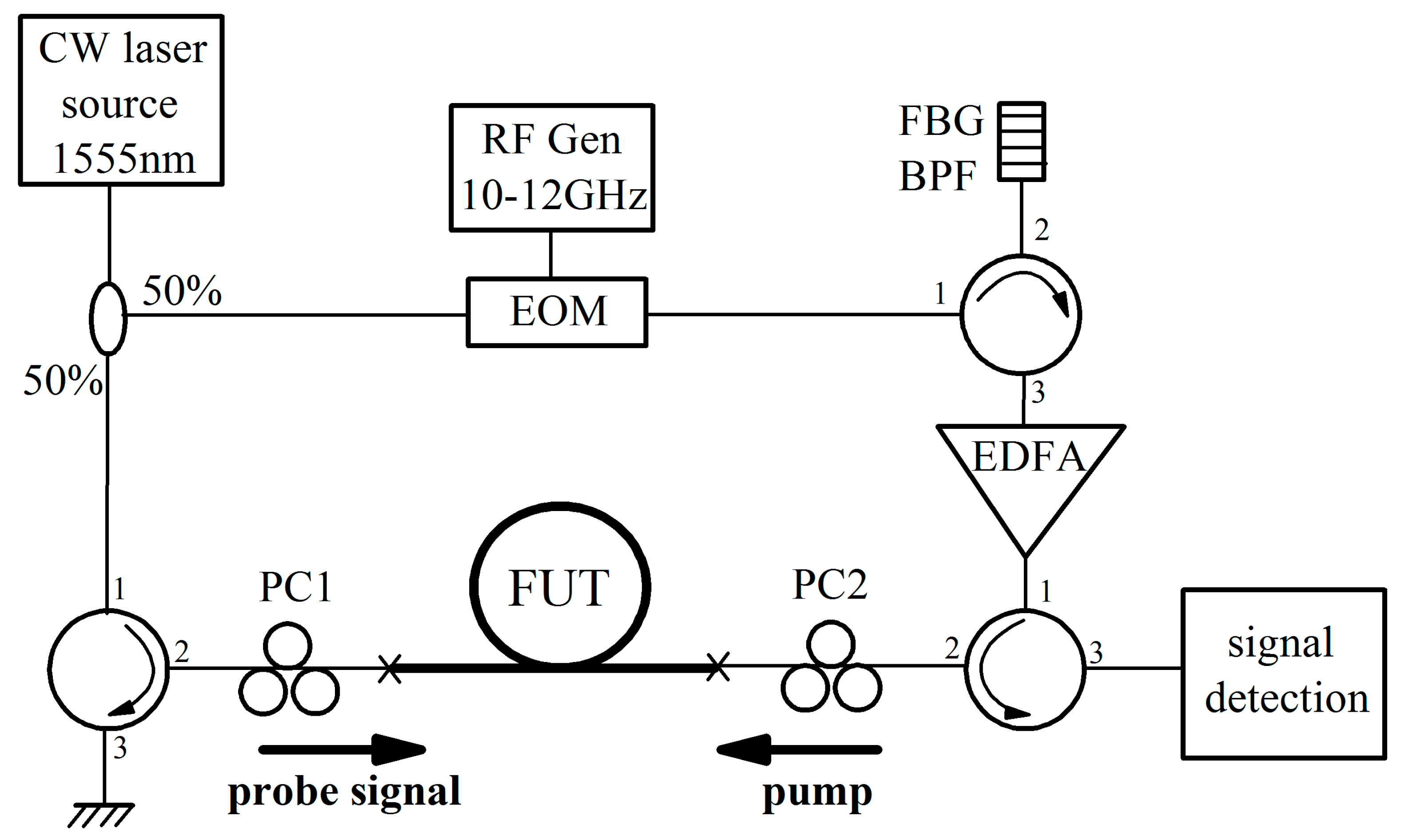
3.2. Measurements of the SBS Gain Spectrum

The measurement setup for the SBS gain spectrum, shown in Figure 5, implements a well-known pump-probe method [37]. The point is that we launch a weak probe signal (~1 mW) and pump radiation (~200 mW) toward each other. The latter is obtained by modulating the radiation from the DFB CW laser at a wavelength of 1555 nm (the linewidth is less than 1 MHz) common for the probe signal and pump, as well as filtering and amplifying the modulation band, which is spaced from the central one by an amount set using a controlled radio-frequency generator and corresponding to the Brillouin frequency shift in the range of 10–12 GHz. In the fiber under test (FUT), the probe signal is amplified in the presence of the pump due to SBS, controlled via two polarization controllers. Through the corresponding circulator, the amplified (or not) probe signal enters the detection circuit (in our case, comprising a photodetector connected to a lock-in amplifier).
The SBS gain was estimated in the undepleted pump approximation, according to the formula:
g B = [ ln ( I pump _ ON min I pump _ OFF ) + ln ( I pump _ ON max I pump _ OFF ) ] A eff P pump L eff ,
where I pump _ ON min , max and I pump _ OFF are measures of probe signal intensities recorded when the EDFA amplifier pump is turned on and off, respectively; Ppump is the measured pump power injected into the FUT; and Leff = [1 − exp(−αL)]/α is the effective length of the FUT of length L, taking into account the loss coefficient α. It is important to note that the intensity of the amplified signal depends significantly on the distribution of signal and pump polarization states along the fiber. Since no tested fibers were maintaining the polarization state, two values of the intensity measure of the amplified probe signal were obtained—the minimum I pump _ ON min and the maximum I pump _ ON max . In this case, there was an uncertainty to each of the values amounting to ±25% of the values that should have been obtained while maintaining the linear polarization states of the signal and pump. Thus, the maximum values (max gB) of the SBS gain in this experiment were determined with an accuracy of ±33%. Table 3 shows the results obtained for the AlGePF fiber and the control one, and Figure 4d shows the measured SBS gain spectra.
In principle, the obtained estimates of max gB were in good agreement with the model ones, and gave a suppression value for the SBS gain of ~11 dB. However, in view of the above uncertainty, we also carried out measurements of the threshold values of the SBS power in each fiber.

3.3. Measurements of the SBS Power Threshold

The scheme for measuring the SBS power threshold is shown in Figure 6a. Since the AlGePF fiber has a relatively high SBS threshold, a pulsed laser radiation source (based on the DFB laser source modulated with the acousto-optical modulator) was used for measurements (pulse length 2.5 μs, repetition rate 2.5 kHz, level of amplified spontaneous emission (ASE) less than 0.5%, linewidth less than 1 MHz). Therefore, the pulse instability (PI) detection method was used to record the SBS threshold. Its essence is that when the threshold is reached, the back-reflected SBS pulse is amplified in the EDFA amplifier stage and removes a significant part of the population inversion created by the pump radiation. Thus, the subsequent part of the pump pulse cannot be fully amplified, which is accordingly reflected in its oscillogram in the form of shape distortion, starting from the trailing edge.
The choice of pulse regime parameters (duration and repetition rate) is related to both the length of the FUT and the achievement of sufficient peak power to observe PI in all fibers tested. The minimum pulse duration in such an experiment is related to the maximum length LFUT of the FUT, taking into account the length LEDFA of the pre-FUT amplifier (LEDFA ~3 m in our setup). To confidently observe the PI effect, it is necessary that the pulse duration τ satisfies the condition: τ > 2∙(LFUT + LEDFA)/(cng), where c is the speed of light in a vacuum, and ng is the group velocity of pulse propagation in the fiber. This condition ensures complete spatial overlap of the incoming pulse and the SBS reflected one in the EDFA segment. In our case, the maximum value of LFUT is ~200 m, and ng ~1.5. Thus, τ should be no less than ~1 μs. However, so that at a given length LFUT >> LEDFA, both the undistorted leading and distorted trailing regions were simultaneously clearly visible on the oscillogram of the transmitted pulse, we chose the increased duration τ = 2.5 μs. At this duration, the distorted pulse part was ~30% of the total pulse duration.
The choice of pulse repetition frequency νpulse is associated with the condition of the minimum duty cycle Q required to achieve a peak power sufficient to overcome the SBS threshold in the FUT. In our case, the maximum average power at the output of the amplifier Pout was ~300 mW. Meanwhile, the estimated SBS power threshold in AlGePF fiber is Pth ≈ 20Aeff/(gB,maxLeff) ~30 W [38]. Since with a square pulse shape, the peak power Ppeak= Pout/Q, then the duty cycle in this case should be no less than Q = (νpulseτ)−1 = 100. However, too high a duty cycle (too low a pulse repetition rate) can lead to an increased ASE onset in the recorded signal. Therefore, we chose a pulse repetition value of νpulse = 2.5 kHz, which provided Q = 160 and a maximum peak power Ppeak ~50 W, sufficient for the experiment and not leading to the undesirable ASE onset.
Figure 6b shows the appearance of PI for the 190 m length AlGePF fiber at a peak power of almost 30 W. In the control fiber of similar length, PI was observed at only 2 W (Figure 6c). We also conducted an additional experiment, selecting the length of the control fiber as 7.5 m, at which its SBS threshold coincidedwith the threshold of the AlGePF fiber (Figure 6d).
During the experiments, we obtained two estimates of the degree of increase in the SBS power threshold in the AlGePF fiber compared to the control fiber—11.2 and 13.5 dB (the difference in the effective areas of the optical mode was also taken into account). In the first case, we compared fibers of the same length and found that the PI threshold for the control fiber was observed at a peak power 11.2 dB lower than that of the AlGePF fiber. In the second case, for the control fiber, we achieved the PI threshold at the same peak power, but its length was 25 times shorter compared to the length of the AlGePF fiber, which corresponded to a 13.5 dB increase in the SBS threshold, given the slightly larger mode area of the AlGePF fiber. Both methods provedto strongly suppress the SBS gain in AlGePF fiber, with the discrepancies between them due to the inherent inaccuracy discussed below.

4. Discussion

Measuring the PI threshold in two long fibers of the same length (190 m) eliminates the problem of controlling the polarization state of the pump along the fiber since over such a long length, one can assume almost complete mixing of all polarization states [39]. However, some error may occur due to different operating regimes of the EDFA (see Figure 6a). When generating pulses with a peak power of 2 W, the EDFA gain was ~12 dB less compared to the regime when pulses were generated with a peak power of 30 W, providing the corresponding gain ratio for the SBS-reflected signals. With this setup, in order to obtain the same relative power levels of the amplified SBS signals, it is also necessary that the absolute values of their powers at the EDFA input are also the same. So, when properly comparing the SBS power thresholds of the two FUTs, with the 30 W peak-power regime, the actual SBS power threshold should be slightly higher. Thus, we can conclude that, in this case, the SBS gain suppression may have been underestimated and that the actual SBS suppression exceeded 11.2 dB.
With different fiber lengths allowing for achieving the same PI threshold, the EDFA operates under the same conditions (same gain) since approximately the same amount of SBS power initiating the PI process reflects from the FUT in both cases. However, since the FUTs are not polarization maintaining, the polarization state of signal may be different in AlGePF and control fibers, resulting in some measurement error. Indeed, we observed that changing the polarization state using the polarization controller (PC) installed in front of the EDFA (see Figure 6a) did not affect the PI threshold. This was not the case for the relatively short 7.5 m control fiber, where changing the polarization state affected the measured PI threshold by 10–15%. In the worst case, discrepancy between different polarization states can lead to an error of 33% in the PI threshold measurements; therefore, we can conclude that the SBS gain suppression in this case was 13.5 ± 1 dB.
It is worth noting that the level of 11.2 dB is quite close to our estimation of maximum SBS suppression for the chosen compound of the AlGePF fiber, and only a small improvement (by ~1 dB) could be achieved when perfect (corresponding to theoretically proposed) dopant distributions were realized. To the best of our knowledge, the obtained value of the SBS gain suppression is a record high for passive LMA fibers, which are not stretched or heated. Indeed, the previous record was ~8 dB [16].
The reduction in AlGePF fiber length down to ~1 m can increase the SBS peak power threshold up to a level of 5 kW, which exceeds the record peak power achieved in the current all-fiber amplifier operated near 1.55 μm. Thus, the developed fiber would allow for adding the required fiber components at the output of an amplifier without deterioration of the maximum peak power.

Author Contributions

Conceptualization, S.T. and M.L.; methodology, T.Z., M.K. and L.K.; software, S.T.; validation, A.L., D.L. and L.I.; investigation, S.T.; resources, A.L. and D.L.; data curation, T.Z. and L.I.; writing—original draft preparation, S.T.; writing—review and editing, M.L. and M.K.; supervision, M.L. All authors have read and agreed to the published version of the manuscript.

Funding

This work was supported by the Center of Excellence “Center of Photonics” funded by the Ministry of Science and Higher Education of the Russian Federation under Contract 075-15-2022-315/22.

Data Availability Statement

No new data were created or analyzed in this study. Data sharing is not applicable to this article.

Conflicts of Interest

The authors declare no conflict of interest.

References

  1. Canat, G.; Lombard, L.; Le Gouët, J.; Dolfi-Bouteyre, A. Kilowatt level transform-limited 150 ns monolithic pulsed fiber laser emitting in the L band. In Proceedings of the Conference on Lasers and Electro-Optics—International Quantum Electronics Conference, Munich, Germany, 12–16 May 2013. paper CJ_5_6. [Google Scholar]
  2. Kotov, L.; Likhachev, M.; Bubnov, M.; Paramonov, V.; Belovolov, M.; Lipatov, D.; Guryanov, A. Record-peak-power all-fiber single-frequency 1550 nm laser. Laser Phys. Lett. 2014, 11, 095102–095107. [Google Scholar] [CrossRef]
  3. Huang, Y.; Pan, P.; Wang, Z.; Tian, J.; Li, D.; Gong, M. 2.19 kW narrow linewidth FBG-based MOPA configuration fiber laser. Opt. Expr. 2019, 27, 3136–3145. [Google Scholar] [CrossRef]
  4. Kerttula, J.; Filippov, V.; Chamorovskii, Y.; Ustimchik, V.; Golant, K.; Okhotnikov, O. Tapered fiber amplifier with high gain and output power. Laser Phys. 2012, 22, 1734–1738. [Google Scholar] [CrossRef]
  5. Mermelstein, M.; Andrejco, M.; Fini, J.; Yablon, A.; Headley, C.; DiGiovanni, D. 11.2 dB SBS gain suppression in a large mode area Yb-doped optical fiber. Proc. SPIE 2008, 6873, 68730N1–68730N7. [Google Scholar]
  6. Zhang, X.; Diao, W.; Liu, Y.; Liu, J.; Hou, X.; Chen, W. Single-frequency polarized eye-safe all-fiber laser with peak power over kilowatt. Appl. Phys. B 2014, 115, 123–127. [Google Scholar] [CrossRef]
  7. Lombard, L.; Dolfi-Bouteyre, A.; Besson, C.; Augère, B.; Bourdon, P.; Durécu, A.; Goular, D.; Le Gouët, J.; Planchat, C.; Renard, W.; et al. Long range wind lidars based on novel high spectral brilliance all-fibered sources. Proc. SPIE 2015, 9645, 96450B1–96450B12. [Google Scholar]
  8. Feng, Y.; Harish, A.; Feng, Y.; Zhao, N.; Nillson, J. Simulation on thermal load gradient mitigation with auxiliary multi-seeds amplification in fiber amplifier. In Proceedings of the 7th EPS-QEOD Europhoton Conference: Solid State, Fibre, and Waveguide Coherent Light Sources, Vienna, Austria, 21–26 August 2016. [Google Scholar]
  9. Dragic, P.; Liu, C.; Papen, G.; Galvanauskas, A. Optical fiber with an acoustic guiding layer for stimulated Brillouin scattering suppression. In Proceedings of the Conference on Lasers and Electro-Optics, Baltimore, MD, USA, 22–27 May 2005. paper CThZ3. [Google Scholar]
  10. Dragic, P. Acoustical-optical fibers for control of stimulated Brillouin scattering. In Proceedings of the 2006 Digest of the LEOS Summer Topical Meeting, Quebec City, QC, Canada, 17–19 July 2006; pp. 3–4. [Google Scholar]
  11. Li, M.; Chen, X.; Wang, J.; Gray, S.; Liu, A.; Demeritt, J.; Ruffin, A.; Crowley, A.; Walton, D.; Zenteno, L. Al/Ge co-doped large mode area fiber with high SBS threshold. Opt. Express 2007, 15, 8290–8299. [Google Scholar] [CrossRef] [PubMed]
  12. Thomas, P.; Lowell, N.; van Oriel, H.; Stegeman, G. Normal acoustic modes and Brillouin scattering in single-mode optical fibers. Phys. Rev. B 1979, 19, 4986–4998. [Google Scholar] [CrossRef]
  13. Jen, C.-K.; Safaai-Jazi, A.; Farnell, W. Leaky modes in weakly guiding fiber acoustic waveguides. IEEE Trans. Ultrason. Ferroelectr. Freq. Control 1986, 33, 634–643. [Google Scholar]
  14. Dong, L. Limits of stimulated Brillouin scattering suppression in optical fibers with transverse acoustic waveguide designs. J. Lightw. Technol. 2010, 28, 3156–3161. [Google Scholar]
  15. Yoo, S.; Codemard, C.; Jeong, Y.; Sahu, J.; Nilsson, J. Analysis and optimization of acoustic speed profiles with large transverse variations for mitigation of stimulated Brillouin scattering in optical fibers. Appl. Opt. 2010, 49, 1388–1399. [Google Scholar] [CrossRef] [PubMed]
  16. Tsvetkov, S.; Khudyakov, M.; Lobanov, A.; Lipatov, D.; Bubnov, M.; Guryanov, A.; Temyanko, V.; Likhachev, M. SBS gain suppression in a passive single-mode optical fiber by the multi-mode acoustic waveguide design. J. Lightw. Technol. 2021, 39, 592–599. [Google Scholar] [CrossRef]
  17. LMA-GDF-30_250-09M, LMA-GDF-30/250-09M, Matched Passive Double Clad, Optical Fiber. Available online: https://coherentinc.my.site.com/Coherent/specialty-optical-fibers/ (accessed on 1 January 2021).
  18. Lipatov, D.; Lobanov, A.; Guryanov, A.; Umnikov, A.; Abramov, A.; Khudyakov, M.; Likhachev, M.; Morozov, O. Fabrication and Characterization of Er/Yb Co-Doped Fluorophosphosilicate Glass Core Optical Fibers. Fibers 2021, 9, 15–25. [Google Scholar] [CrossRef]
  19. Jen, C.-K.; Neron, C.; Shang, A.; Abe, K.; Bonnell, L.; Kushibiki, J. Acoustic characterization of silica glasses. J. Am. Ceram. Soc. 1993, 76, 712–716. [Google Scholar] [CrossRef]
  20. Dragic, P.; Ballato, J.; Ballato, A.; Morris, S.; Hawkins, T.; Law, P.-C.; Ghosh, S.; Paul, M.C. Mass density and the Brillouin spectroscopy of aluminosilicate optical fibers. Opt. Mater. Express 2012, 2, 1641–1654. [Google Scholar] [CrossRef]
  21. Dragic, P.; Cavillon, M.; Ballato, J. The linear and nonlinear refractive index of amorphous Al2O3 deduced from aluminosilicate optical fibers. Int. J. Appl. Glass Sci. 2017, 9, 421–427. [Google Scholar] [CrossRef]
  22. Nakanishi, T.; Tanaka, M.; Hasegawa, T.; Hirano, M.; Okuno, T.; Onishi, M. Al2O3-SiO2 core highly nonlinear dispersion-shifted fiber with Brillouin gain suppression improved by 6.1 dB. Proc. ECOC 2006, 6, 17–18. [Google Scholar]
  23. Butov, O.V.; Golant, K.M.; Tomashuk, A.L.; van Stralen, M.J.N.; Breuls, A.H.E. Refractive index dispersion of doped silica for fiber optics. Opt. Comm. 2002, 213, 301–308. [Google Scholar] [CrossRef]
  24. Deroh, M.; Kibler, B.; Maillotte, H.; Sylvestre, T.; Beugnot, J. Large Brillouin gain in Germania-doped core optical fibers up to a 98 mol% doping level. Opt. Lett. 2018, 43, 4005–4008. [Google Scholar] [CrossRef]
  25. Koyamada, Y.; Sato, S.; Nakamura, S.; Sotobayashi, H.; Chujo, W. Simulating and designing Brillouin gain spectrum in singlemode fibers. J. Lightw. Technol. 2004, 22, 631–639. [Google Scholar] [CrossRef]
  26. Lagakos, N.; Bucaro, J.A.; Hughes, R. Acoustic sensitivity predictions of single-mode optical fibers using Brillouin scattering. Appl. Opt. 1980, 19, 3668–3670. [Google Scholar] [CrossRef] [PubMed]
  27. Yeniay, A.; Delavaux, J.-M.; Toulouse, J. Spontaneous and stimulated Brillouin scattering gain spectra in optical fibers. J. Lightw. Technol. 2002, 20, 1425–1432. [Google Scholar] [CrossRef]
  28. Dragic, P. Estimating the effect of Ge doping on the acoustic damping coefficient via a highly Ge-doped MCVD silica fiber. J. Opt. Soc. Am. B 2009, 26, 1614–1620. [Google Scholar] [CrossRef]
  29. Law, P.-C.; Liu, Y.-S.; Croteau, A.; Dragic, P.D. Acoustic coefficients of P2O5-doped silica fiber: Acoustic velocity, acoustic attenuation, and thermo-acoustic coefficient. Opt. Expr. 2011, 1, 686–699. [Google Scholar] [CrossRef]
  30. Bubnov, M.M.; Dianov, E.M.; Egorova, O.N.; Semjonov, S.L.; Guryanov, A.N.; Khopin, V.F.; DeLiso, E.M. Fabrication and investigation of single-mode highly Phosphorus-doped fibers for Raman lasers. Proc. SPIE Adv. Fiber Opt. 2000, 4083, 12–22. [Google Scholar]
  31. Fleming, J.W.; Wood, D.L. Refractive index dispersion and related properties in fluorine doped silica. Appl. Opt. 1983, 22, 3102–3104. [Google Scholar] [CrossRef]
  32. Guryanov, A.; Salganskii, M.; Khopin, V.; Kosolapov, A.; Semenov, S. High-aperture optical waveguides based on fluorine-doped silica glass. Inorg. Mater. 2009, 45, 823–826. [Google Scholar] [CrossRef]
  33. Agrawal, G. Nonlinear Fiber Optics, 5th ed.; Elsevier: Amsterdam, The Netherlands, 2013; pp. 353–396. [Google Scholar]
  34. Kobyakov, A.; Kumar, S.; Chowdhury, D.Q.; Ruffin, A.B.; Sauer, M.; Bickham, S.R. Desing concept for optical fibers with enhanced SBS threshold. Opt. Expr. 2005, 13, 5338–5346. [Google Scholar] [CrossRef]
  35. Shibata, N.; Okamoto, K.; Azuma, Y. Longitudinal acoustic modes and Brillouin-gain spectra for GeO2-doped-core singlemode fibers. J. Opt. Soc. Am. B 1989, 6, 1167–1174. [Google Scholar] [CrossRef]
  36. DiGiovanni, D.; MacChesney, J.; Kometani, T. Structure and properties of silica containing aluminum and phosphorus near the AlPO4 join. J. Non-Crystal. Solids 1989, 113, 58–64. [Google Scholar] [CrossRef]
  37. Garus, D.; Krebber, K.; Schliep, F.; Gogolla, T. Distributed sensing technique based on Brillouin optical-fiber frequency-domain analysis. Opt. Lett. 1996, 21, 1402–1404. [Google Scholar] [CrossRef] [PubMed]
  38. Ippen, E.; Stolen, R. Stimulated Brillouin scattering in optical fibers. Appl. Phys. Lett. 1972, 21, 539–541. [Google Scholar] [CrossRef]
  39. Horiguchi, T.; Tateda, M.; Shibata, N.; Azuma, Y. Brillouin gain variation due to a polarization-state change of the pump or Stokes field in standard single-mode fibers. Opt. Lett. 1989, 14, 329–331. [Google Scholar] [CrossRef] [PubMed]
Figure 1. Basics of the core design.
Photonics 10 01150 g001
Figure 2. Modeling: dopant molar concentrations (a), ARIP (b) and optical refractive index profile (ORIP) (c) of the acoustically optimized fiber; (d) Brillouin gain spectra gB(f) of the optimized and a conventional 2.2 mol%P2O5-doped LMA fibers withthe same ORIP, where the frequency ranges provided by maximal concentrations of Al2O3 and P2O5 + F are marked.
Photonics 10 01150 g002
Figure 3. Near-field patterns taken by the IRcamera of the mode field distribution at the output of the 11 cm coiled 190 m length AlGePF fiber demonstrating an absence of the onset of the higher-order mode (LP11, etc.) pattern for different shifts of an excitation position from the center to the periphery at 1.55 μm.
Photonics 10 01150 g003
Figure 4. Experimental results: measured dopant molar concentrations (a), calculated ARIP (b) and measured ORIP (c) of the acoustically optimized AlGePF fiber; (d) Brillouin gain spectra gB(f) of the optimized AlGePF fiber and the control LMA fiber with the same ORIP, where the frequency ranges provided by maximal concentrations of Al2O3 and P2O5 + F are marked.
Photonics 10 01150 g004
Figure 5. SBS gain measurement setup. RF Gen is the radio-frequency generator; EOM is the electro-optical modulatorforming two side bands in the pump spectrum spaced from the central frequency by an amount set by the RF-generator; FBG BPF is the fiber Bragg grating band-pass filter leaving only the left side-band in the pump spectrum; FUT is the fiber under test; PC1 and PC2 are the polarization controllers setting the states of input polarizations for the probe signaland the pump, respectively, which allows for controlling the minimum and maximum Brillouin gain.
Photonics 10 01150 g005
Figure 6. Scheme of the experimental setup for SBS power threshold measurement (a) and oscilloscope plots of pulses just before and just after reaching the SBS power threshold with pulse instability (PI) observed for the 190 m length AlGePF fiber (b), the 190 m length control fiber (c), and the 7.5 m length control fiber (d) withthe same threshold as 190 m length AlGePF fiber.
Photonics 10 01150 g006
Table 1. Acousto-optical properties of the dopants.
Dopant, XRac,X, mol%−1Rop,X, mol%−1Kf, MHz/mol% at λ = 1.55 μm
Al2O3−4.5 × 10⁻³ [19,20,22]2.16 × 10⁻³ [20,21,22,23]+50
GeO27.9 × 10−3 [19,24,25,26,27,28]1.45 × 10⁻³ [23,24,26]−87
P2O59 × 10−3 [16,29]0.9 × 10⁻³ [29,30]−99
F9.4 × 10−3 [19,25]−1.6 × 10⁻³ [31,32]−107
Table 2. Basic properties of the AlGePF fiber and the control one.
FibernCore Radius, μmAeff, μm2λcutoff, μm[email protected] μm, dB/km
AlGePF0.00215.537032.7 (coiled on ∅11 cm)
Control0.0014103251.52
Table 3. Results of estimation of the SBS gain coefficient.
Fibermax gB, pm/WL(Leff), mfB, MHzPpump, mW
AlGePF1.1200 (187)~60270
Control13.452 (43.5)34190
Disclaimer/Publisher’s Note: The statements, opinions and data contained in all publications are solely those of the individual author(s) and contributor(s) and not of MDPI and/or the editor(s). MDPI and/or the editor(s) disclaim responsibility for any injury to people or property resulting from any ideas, methods, instructions or products referred to in the content.

