Article

Analysis of Coaxiality Error Induced by the Cube Corner Retro-Reflector Geometrical and Assembly Errors of an Acquisition, Pointing, and Tracking System

1
Unmanned System Research Institute, Northwestern Polytechnical University, 127 West Youyi Road, Beilin District, Xi’an 710072, China
2
Aerospaces Military Representative Administration, Lianhu District, Xi’an 710082, China
3
Xi’an Institute of Optical Precision Machinery, Chinese Academy of Sciences, NO.17 Xinxi Road, New Industrial Park, Xi’an Hi-Tech Industrial Development Zone, Xi’an 710119, China
4
School of Opto-Electronics Engineering, Xi’an Technological University, Xi’an 710021, China
*
Authors to whom correspondence should be addressed.
Photonics 2023, 10(10), 1176; https://doi.org/10.3390/photonics10101176
Submission received: 25 August 2023 / Revised: 24 September 2023 / Accepted: 3 October 2023 / Published: 23 October 2023
(This article belongs to the Special Issue Optical Imaging and Measurements)

Abstract

:
Satellite laser communication is a promising technology for the next-generation communication system. Its communication performance is subject to the APT beam-pointing accuracy. One of the most important problems is reducing the coaxiality error before the APT starts working. However, the coaxiality error is difficult to correct effectively owing to the lack of empirical guidance based on qualitative analysis. We study the inducement that will generate coaxiality errors. The mathematical model of the influence of the CCR dihedral angle error and planeness error on the spot centroid measurement are built, and an analysis is performed. The model of the beam-pointing error induced by the APT element’s assembly error is built, and the pointing error change rule is explored. Furthermore, the coaxiality performance simulation is performed in the presence of a CCR geometrical error while considering the assembly error. The results show that the coaxiality error has a nonlinear characteristic. The CCR planeness error has a greater influence on coaxiality deviation than that of dihedral angle error under certain conditions. This research is relevant to the design and test work of the APT system.

1. Introduction

For the convenience of reading, most acronyms and symbols used here are listed in Table 1.
Satellite laser communication received global attention for its high-speed communication rate, good confidentiality, small size, and lightweight terminal. Its communication rate is two orders of magnitude higher than conventional satellite microwave communication, which can reach the Gbps level [1,2,3]. In the early stage of the proposition of this technique, the communication terminals were mainly used for principle verification, and scientists have conducted many experimental verifications between different links, such as LEO-LEO (Low Earth Orbit), LEO-MEO (Medium Earth Orbit), LEO-GEO (Geosynchronous Earth Orbit) and GEO-GEO links. However, after decades of development, networking communication engineering applications, such as the Star Link plan of Space X Ltd., Cardiff, UK, the Europe data relay system (EDRS) [4], and China’s sky and earth integrated information network gradually stepped onto the stage [5]. Therefore, the development of technology has put forward a higher standard for the performance of the terminal [6]. In a typical satellite laser communication system, a communication modulation subsystem, a beam-pointing subsystem (also known as APT (Acquisition, Pointing, and Tracking)), and a telescope subsystem are required. The beam-pointing subsystem is mainly responsible for controlling the incoming and outgoing beam direction for the acquisition, tracking, and pointing of the target in advance, but the pointing beam is very narrow, and the beam width used in communication links is usually tens of microradians, hence a little pointing error angle will lead to an increase in the communication error rate, or even cause the interruption of the link. Therefore, the beam-pointing accuracy is very important [7]. Thus, precise pointing mechanisms (such as a fast-steering mirror) are usually used to improve the beam-pointing angle when the terminal is launched into orbit [8]. Before the system begins to communicate, the target must be stably tracked (i.e., the incoming beam angle must be accurately obtained) by a fine tracking path. The point-ahead mirror controls the communication beam, causing it to rotate by a small angle relative to the direction of the incoming beam and point towards the target satellite. Therefore, if there is an inherent error in the angle between the transmitting and receiving paths, the point-ahead beam direction will deviate from the ideal angle during communication, which is called a coaxiality error (CE). A CE will significantly affect the performance of the APT system, such as acquisition probability and link stability. Before a satellite is launched into orbit and prepared to capture the target, the CE requires rigorous calibration such that the transmitting and receiving paths are parallel to each other. The beam can then point precisely toward the target bearing. However, various factors influence coaxiality errors, such as assembly, vibration and detection system errors [9], making it difficult to reduce the CE. Hence, rigorous corrective measures are required to reduce the CE based on the measurement results.
Generally, the cube corner retro-reflector (CCR) is used in coaxiality calibration because of its good beam back-reflection characteristic. Wang et al. [10] used the CCR to measure the accuracy of the CE and point-ahead angle. The laser source emits communication light, and the light is transferred throughout the APT system. The CCR is set at the surface of the telescope, then the communication light is reflected back into the APT system by CCR and transferred to the surface of the acquisition detector. In this way, the CE can be determined by measuring the displacement between the centroid of the incoming and outgoing beam faculae. Thus, the errors leading to CE can be introduced in every unit when the beam passes through. Among the inducements of CE, the most important factors are CCR geometric errors (which are mainly dihedral angle error and planeness error) and APT elements assembly errors. The assembly error mainly refers to the reflector elements’ posture error or the rotation error of the APT axis, which will directly affect the beam-pointing direction. On the other hand, because light diffracts when it pass through any objects, if the beam is reflected by the CCR, the faculae is affected not only by the APT reflector elements but also by the CCR. Under general conditions, however, the faculae distortion caused by the reflector elements can be ignored during the calibration process. Thus the faculae centroid error is mainly caused by the dihedral angle error and planeness error from the CCR. The dihedral error is caused by the perpendicular error angle between two faces of the CCR, while the planeness error is caused by the unevenness of each face of the CCR. These two factors can affect the spot energy distribution and reduce coaxiality. Presently, some researchers introduced the influence of the reflective element assembly error on beam-pointing accuracy of the APT system. For example, Yu et al. [11] investigated the static position errors during the assembly of the HY-2 satellite optical communication terminal, while Wu et al. examined the pointing error caused by the axis error angle in a periscope-type APT [12]. The dihedral angle error and planeness error of the CCR and their influence on the laser spot energy distribution have been studied extensively, for example, by Weng, who analyzed the planeness error of the CCR, establishing the mathematical model of planeness error [13], and by Nie, who analyzed the CCR geometric error and studied the far-field diffractive characteristics of the CCR [14]. However, the CE has not been studied in the presence of assembly error.
Moreover, considering the CCR error, in some studies, the CCR is only used to calibrate the signal-receiving-transmission coaxial sub-module of the APT but not the whole APT system [15]. Therefore, some factors have not been considered in previous studies. Hence, this study mainly focuses on the characteristics of the CE change rule, attempting to analyze the influence of coupling factors on the CE and focusing on the challenge of establishing the analysis model under the influence of coupling factors. The solution to this problem can effectively help us obtain the variation characteristics of the CE, improving assembly efficiency and enhancing the performance of the APT systems.
This study examines the geometric error of the CCR and the assembly error of the APT system, establishes the CE analysis model, and investigates the change characteristics. The remainder of this paper is organized as follows: The CE measurement method based on CCR is introduced in the Section 2. In the Section 3, the influence of the dihedral angle error and planeness error of the CCR on the wavefront is analyzed. The coaxiality is studied in the presence of assembly error while considering CCR error in the Section 4. The discussion and conclusion are presented in the Section 5 and Section 6.

2. Coaxiality Measurement Method

The CE of the APT system is primarily influenced by the error of the angle between the transmitting optical path (beam outgoing path) and the communication optical path (beam receiving path). The point-ahead mirror usually works in an open loop. However, for satellite laser communication, coaxiality is usually constrained at the microradian level; hence, a special on-orbit calibration scheme is needed to reduce the CE. The CE measurement system based on CCR is illustrated in Figure 1. Here, a periscope-type APT is selected as the research target. The CE detection process is as follows. The signal beam is sent out from the laser source, and then the beam is expanded by the lens. Afterward, the beam is reflected by the point-ahead mirror (PAM), Mirror 1, fast-steering mirror (FSM), azimuth folding mirror, and elevation folding mirror sequentially. Then, the beam goes out of the APT system, is reflected by the CCR, and goes back in the same direction. Then, the beam is reflected by the elevation folding mirror, azimuth folding mirror, FSM, and Mirror 2. The blue arrows denote the direction of outgoing light, and the green arrows denote the direction of incoming light.
Finally, the beam is focused on the surface of the CCD (Charge-coupled Device). The CE can be determined by measuring the displacement deviation between the centroid of the reflected spot and the detector center. Suppose that the beam transmits through the APT system. In such instances, the beam direction will deflect from the original direction when the mirror is error assembled, and the laser spot energy distribution is destroyed by the CCR with a geometrical machining error. Under the joint action of both errors, the spot centroid will deviate from the detector center. It is important to note that the PAA and FSM’s position errors are mainly relevant when the APT is powered on. This kind of error can be corrected based on the feedback signal from the position detector, such as the eddy current sensor. So, the assembly error of Mirror 1, Mirror 2, azimuth folding mirror, and elevation folding mirror are under primary consideration.
In Figure 1, the acronyms have the following meanings: CCR refers to the cube corner retro-reflector; El FM refers to the elevation folding mirror; Az FM refers to the azimuth folding mirror; PAM refers to the point ahead mirror; M1 refers to the Mirror 1; and M2 refers to the Mirror 2. O-xyz is the coordinate of the APT system, where axis o-x is parallel to the laser, o-z is parallel to the azimuth axis, and o-y can be defined by the right-hand principle.

3. Error Modeling and Analysis

This part mainly focuses on the modeling of the geometrical error of the CCR, after which the wavefront transmission error is analyzed. Based on this analysis, the energy distribution of the backscattered light spots from the CCR is simulated, and the influence of assembly error on beam-pointing accuracy is also analyzed.

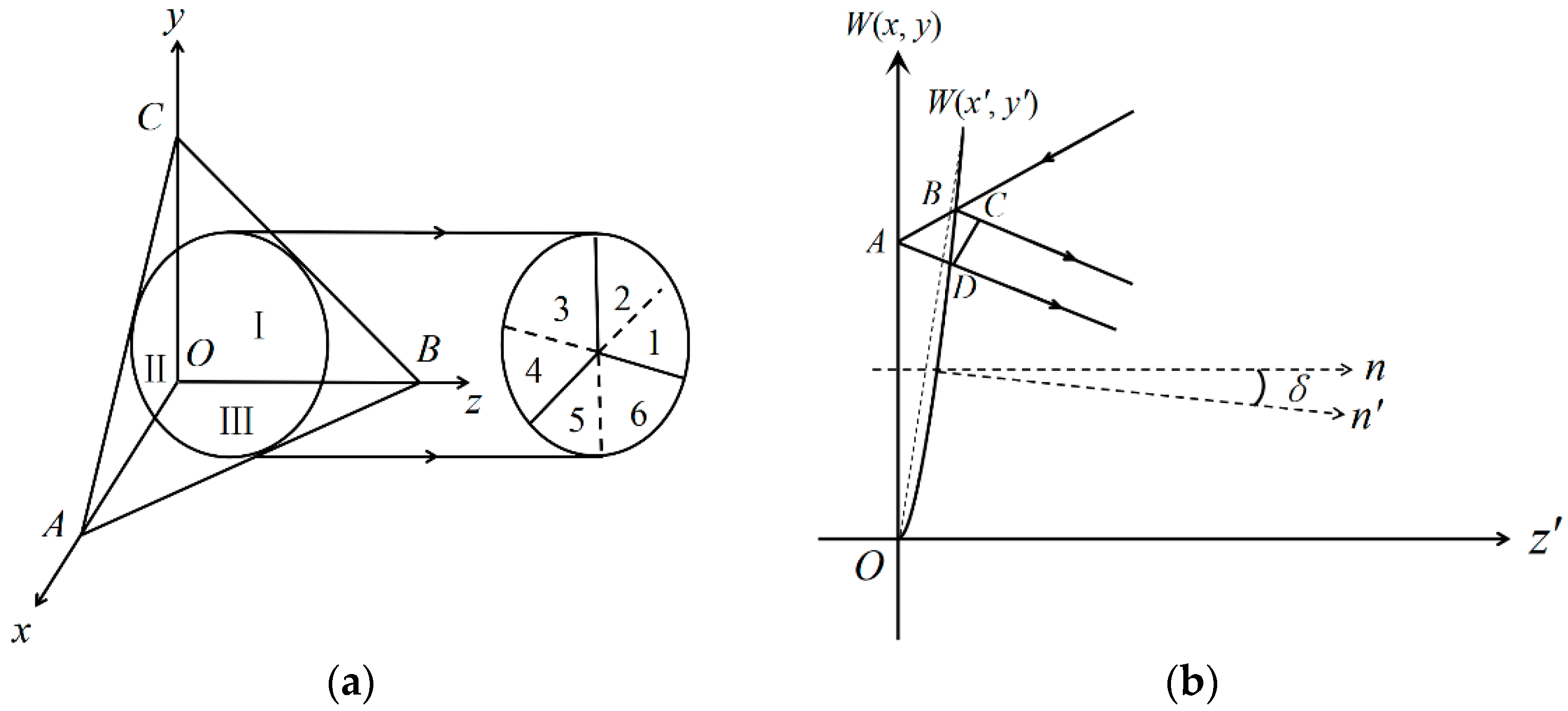
3.1. Geometrical Error of CCR

The CCR is a tetrahedral prism with three orthogonal surfaces. If the beam incidence is directed toward the CCR, it will be retro-reflected by three mirrors and produce six reflection sequences (123, 132, 213, 231, 312, and 321). Hence, the spot will be divided into six equally sized sectors (shown in Figure 2a), and the outgoing beam will be parallel to the income beam but in the opposite direction. As mentioned earlier, there are two kinds of machining errors along with the CCR: dihedral error angle and planeness error. Generally, as shown in Figure 2a, the three surfaces obey the following rule: OAB⊥OBC⊥OAC. However, if there is a dihedral angle error, the angle ceases to be 90° and will be 90°−δij instead (where δij represents the error angle between OAC and OBC, OAB and OAC, and OAB and OBC, and i and j = 1, 2, 3).
Figure 2b shows the geometrical error of the CCR, where W(x, y) is the wavefront of the reflected beam when there is no geometrical error, and n is the normal. Accordingly, W(x’, y’) represents the distorted wavefront of the reflected beam from the CCR along with the dihedral angle error and planeness error, and n’ is the normal. Thus, from Figure 2b, the optical path difference (OPD) induced by the CCR geometrical error can be described as
Δ d = n ( B C ¯ A B ¯ A D ¯ ) .
Because the geometrical error has two parts, the optical path difference can therefore be written as
Δ d = d s + d t .
In Equation (2), ds represents the OPD induced by the dihedral angle error, and dt represents the OPD induced by the planeness error. When a ray of light is reflected, the reflection process can be described as
A = A 2 ( A N ) N .
In Equation (3), A = (Ax, Ay, Az) is the vector of the incoming beam, and A′ = (Ax, Ay, Az) is the vector of the reflected beam. Suppose that δ12, δ23, and δ31 are the dihedral angle error of OAC and OBC, OAB and OAC, and OAB and OBC, respectively, then the normal of Surfaces I, II, and III can be obtained.
N1 = (cos(δ12), 0, sin(δ12)) × (cos(δ31), sin(δ31), 0)
N2 = (sin(δ12), 0, cos(δ12)) × (0, sin(δ23), cos(δ23)).
N3 = (sin(δ31), cos(δ31), 0) × (0, cos(δ23), sin(δ23))
Because δ12, δ23, δ31 is very small, the normals N1, N2, and N3 can thus be rewritten as N1 = (δ12, 0, δ12) × (δ31, δ31, 0); N2 = (δ12, 0, δ12) × (0, δ23, δ23); and N3 = (δ31, δ31, 0) × (0, δ23, δ23). In this way, the laser’s vector going through the three reflectors can be written as follows:
Through   Surface   I :   A 11 = A 11 2 ( A 11 N 1 ) N 1 ;
Through   Surface   II :   A 12 = A 12 2 ( A 12 N 2 ) N 2 = A 11 2 ( A 11 N 2 ) N 2 ;
Through   Surface   III :   A 23 = A 23 2 ( A 23 N 3 ) N 3 = A 12 2 ( A 12 N 3 ) N 3 .
The derived out-ray vectors need to convert into the coordinate in Figure 2b through the transformation described in [16] so that the wavefront solving model can be deduced.
m x + n y + l z = 0 z = d s = ( m x + n y ) / l ,
where m, n, and l are the three components of the vector A23. According to Equations (5)–(8), we can derive the OPD of six sectors induced by the dihedral angle error.
If the surface has a planeness error, its shape is a sphere with a large curvature; therefore, the different position has a different normal. Suppose the additional small quantity caused by the tangential deviation from the ideal reflection point due to the planeness error is not considered. In that case, the composition OPD caused by planeness error is the summation of the OPD caused by three reflection points on three surfaces, which can be described as
d t = j Δ ( x , y ) cos θ i j = 1 , 2 , 3   d t = j Δ ( x , y ) cos θ i j = 1 , 2 , 3 .
In Equation (9), j = 1, 2, 3, which represents different reflective surfaces, (x, y) is the coordinate of the point, and θi represents the ray incoming angle of every point. Suppose that the curvature of a surface is Ri and the vertex of the aperture is in the center of the sector. The expression of the surface with the shape error can then be written as
( x x 0 ) 2 + ( y y 0 ) 2 + ( z + R i ) 2 = R i 2 .
Generally, the Newtonian rings (N1, N2, N3...) are used to evaluate the planeness of a CCR surface, and the conversion relationship can be found in [17]. According to Equations (1)–(10), the OPD of the CCR with dihedral angle error and planeness error can be deduced.
Based on the above analysis, the wavefront simulation is performed in MATLAB, and the results can be seen in Figure 3a–i. The results show that if only the dihedral angle error exists, the wavefront is a regular pattern composed of fan-shaped surfaces of different sizes. If only the surface error exists, the wavefront shape is a regular shape surrounded by six petal-shaped surfaces. If both errors exist, its shape combines the two wavefront shapes. Because the CE is determined according to the beam spot centroid, the beam energy distribution simulation of the reflected laser by the CCR must be performed. In Figure 4a–c, the simulation results are shown, including the reflected beam energy distribution of the CCR without error, only dihedral angle error, only planeness error, and both errors. From the results, we can find that different kinds of CCR geometrical errors have different influences on the spot energy distribution. When both errors exist, the spot energy distribution becomes very messy.

3.2. Influence of Assembly Error on Pointing Accuracy

Another factor affecting CE is assembly error, which mainly contains reflector and axis assembly errors. The reflectors in Figure 1 can be divided into three kinds. The first kinds are the FSM and PAM; these two mirrors will give feedback on the rotation angle information and correct the rotation error based on the feedback signal. The second kind of mirror is Mirrors 1 and 2, which are only used to fold the beam direction. The third kinds of mirrors are the azimuth and elevation folding mirrors. These two mirrors will introduce a CE if they are not well assembled before being utilized, which may cause axis bounce because the CE is measured in a static state; hence, the axis bounce is not considered here. Furthermore, suppose the azimuth axis and elevation axis are not strictly perpendicular (or parallel) to the reference coordinate system after assembly. In that case, it will lead to another rotation error in the folding mirror relative to the reference coordinate (because the axis and folding mirrors are rigidly connected). Based on the above analysis, it is necessary to simulate the influence of an assembly error on the beam-pointing direction.
According to Coordinate o-xyz in Figure 1, take the M1 as the target, and assuming that the rotation error angle induced by assembly error around x, y, and z are αM1, βM1 and γM1, then the rotation matrix of M1 around x, y, and z are
R M 1 x = [ 1 0 0 0 cos α M 1 sin α M 1 0 sin α M 1 cos α M 1 ] , R M 1 y = [ cos β M 1 0 sin β M 1 0 1 0 sin β M 1 0 cos β M 1 ] , R M 1 z = [ cos γ M 1 sin γ M 1 0 sin γ M 1 cos γ M 1 0 0 0 1 ]
According to Figure 1, the normal of M1 is NM1 = [√2/2, −√2/2, 0]; therefore, its new normal after rotation is
N M 1 = R M 1 x R M 1 y R M 1 z N M 1 .
According to Equation (3), we can drive out the reflection matrix of M1 as follows:
A M 1 = E 2 N M 1 ( N M 1 ) T = E 2 R M 1 x R M 1 y R M 1 z N M 1 ( R M 1 x R M 1 y R M 1 z N M 1 ) T .
From Figure 1, we can determine the outgoing beam reflection order, which is PAM→M1, →FSM→Az FM→El FM, and the reflection order of the incoming beam is El FM→Az FM→FSM→M2. At last, for the beam incidence on the surface of the detector, assuming that the vector of the laser from the laser source is Aout = [1, 0, 0], then the outgoing beam vector Aout can be written as
A o u t = A E l A A z A F S M A M 1 A P A M A out .
Assuming that the incoming beam vector is Ain = [0, 0, −1], then similar to Equation (13), the beam vector Ain in the front of the detector after it passes through the system can be derived.
A i n = A M 2 A F S M A A z A E l A i n
The vector Aout is [0, 0, 1]. When Aout passes through the APT system, which is without error, and assuming that Ain is the vector when Ain passes through the system without error, Ain can be written as [0, 1, 0]. We can obtain the error angle through the vector angle formula depending on the vector angle formula.
ε = arccos ( A A | A | | A | )
According to Equation (15), we can derive the pointing error angle between Aout and A″out, A′i, and A″in. The beam-pointing error under different assembly errors is performed. The results can be viewed in Figure 5a–f. The control variate method is adopted in the simulation, assuming we take one of the assembly error values from 0.001° to 0.005° and set other element’s assembly errors to 0.001°, 0.003°, and 0.005° in different groups. For example, to obtain the point error, we take the assembly error of M1, Az axis, Az FM, El axis, and El FM as 0.001°, rotate M2 by 0.001°, 0.003°, and 0.005°, and then record the deviation angles of the incoming light and outgoing light in the corresponding states. Figure 5a–f shows that the assembly error has a nonlinear influence on beam-pointing error, and that the influence of the azimuth axis and azimuth folding mirror, as well as the elevation axis mirror and elevation folding mirror, on beam-pointing accuracy is almost uniformly distributed. This proves that the folding mirror is rigidly connected to the axis. Moreover, in each set of data, there exists an intersection point where the pointing error has the same value, and the position of the intersection point will be increased if the assembly error increases. Furthermore, before the intersection point, the closer the elements to the light source, the greater the effect of the assembly error on the beam offset error angle; however, after the intersection point, the opposite tendency was observed.

4. Coaxiality Error Analysis

The influence of assembly error on beam-pointing accuracy and the influence of the CCR geometrical error (planeness error and dihedral angle error) on the spot energy distribution are analyzed separately. However, the variation characteristics of the CE under the coupling effect of the two factors are unclear. Therefore, further research is necessary. In a typical APT system, the CE measurement method based on CCR calculates the deviation between the centroid of the retro-reflected laser spot and the detector’s center. The determination of the retro-reflected beam-spot centroid is usually solved by the centroid method.
x 0 = ( i = 1 m j = 1 n i I ( x , y ) / i = 1 m j = 1 n I ( x , y ) ) , y 0 = ( i = 1 m j = 1 n j I ( x , y ) / i = 1 m j = 1 n I ( x , y ) )
Then, the CE can be calculated based on the angle measurement principle. The CE caused by the CCR and assembly error simulation is performed using Zemax software. We assume that the convergence lens is ignored in the system and that all the optical elements have no deformation. In each simulation group, we suppose the CCR geometrical error is fixed and gradually increases the assembly error of different APT elements. The distance of the beam’s route from where it is being emitted to where it is being reflected by the CCR and, lastly, where it is being received by the detector is 602 mm, the size of the detector is 6 mm × 6 mm, the pixel number is 350 × 350, and the size of each pixel is approximately 17 um in the simulation. We record the centroid position of the facula on the detector surface with or without CCR, and then calculate the CE based on the two facula centroid positions and the length of the optical path. The results can be viewed in Table 2, Table 3, Table 4, Table 5, Table 6 and Table 7. Compared to the data in Table 2 and Table 6, the planeness error has a great influence on CE, and the error increases by one order of magnitude when other conditions are equal, compared to Figure 2 and Figure 3.
In contrast, each element assembly error of the APT has an inconspicuous different effect on coaxiality. The maximum value of the CE can reach 700 μrad, far beyond the allowable limit of the APT pointing error. In satellite laser communication links, if only the CE is considered, the maximum value of the CE should not exceed the field-of-view angle of the fine-tracking CCD. However, the fine-tracking CCD work bandwidth is very high (Kilohertz level). Its pixels are limited to a small number (tens in value), resulting in a field of view that spans hundreds of microradians. The data in Table 2, Table 3, Table 4 and Table 5 show that the dihedral angle error has less influence on coaxiality than the planeness error because the dihedral error can be treated as a small, peculiar planeness error that has a faster convergence speed. Therefore, in coaxiality measurements, a CCR with a small planeness error is preferred. Comparing the data in Table 6 and Table 7, we find that when the CCR dihedral angle error and planeness error take different values, the coaxiality error steadily shows a downward trend as the assembly error increases, which indicates that there is a counteraction between the two errors; therefore, an appropriate CCR can be selected to reduce the coaxiality error. In practical cases, the PAM works in an open loop, and the CE will affect the communication link stability. However, the inter-satellite link or satellite-to-ground link is defined at a specific time; that is, the rotation angle of the APT has a certain value. Therefore, calibration can be performed to reduce the CE to an acceptable value at these special rotation angles.

5. Discussion

The CE can influence the beam pointing accuracy, particularly the point-ahead beam, which is responsible for communication, but the PAM works in an open loop, which may increase the communication bit error rate or even cause link interruption; therefore, it is necessary to calibrate the CE. We propose that the main factor causing the CE is the beam reflection, as one side involves the reflective element in the APT system, while the other involves the CCR, which is used to retro-reflect the beam. We established a CCR geometric error model for the planeness error and dihedral angle error and analyzed the wavefront of the reflected beam. The facula energy distribution indicated that the combination of the two errors severely deformed the facula. The laser transmission model in the APT system was derived, and the beam-pointing error results indicated that different reflective elements have different influences on the pointing error: the closer the distance to the laser source, the greater the impact on the pointing error before the intersection point. However, after this point, the opposite tendency was observed. This is related to the structural form of the APT system, where each assembly error not only increases the pointing error but may also decrease it; therefore, the pointing-error tendency is not static. The CE simulation results show that the dihedral angle error has less influence on the coaxiality than the planeness error, and there is a measure of counteraction between the errors. We can choose a smaller planeness error CCR in the actual testing process and find a counteracting point to reduce the CE as much as possible.

6. Conclusions

In satellite laser communication, beam-pointing accuracy is crucial for link stability. Thus, precise calibration is required before the terminal starts in-orbit operation, but the factors that affect the coaxiality error are unclear and lack effective adjustment methods. We analyzed the coaxiality error of a periscope-type APT system based on the CCR ray reflection method. The CCR geometrical error was established and analyzed, in which the dihedral angle and planeness errors were considered. The influence mathematical model of the CCR geometrical error on a wavefront was established, and the spot energy distribution was analyzed, the simulation data indicates that even if the wavefront distortion caused by CCR error is symmetrically distributed, the energy distribution of the diffraction faculae is not uniform. Subsequently, the influence of the mirror-element assembly error on APT beam-pointing accuracy was studied after the beam transformation model was established. Then, based on the above analysis, the coaxiality error under the influence of CCR geometrical and APT assembly errors was studied. The results showed that the increase in assembly error made the APT system’s beam-pointing error more linear. The planeness error has a greater influence on the coaxiality error than that of the CCR dihedral angle error. However, if all errors take on different values, there will also be a certain amount of counteraction to the CE; therefore, error balancing can be adopted based on this principle to reduce CE. Moreover, the influence level of each assembly error of the APT system on coaxiality was broadly consistent, and the maximum coaxiality error can reach 700 μrad under the current simulation condition, which is beyond the limit value for the APT system. We hope this study provides some reference for the design of an APT system.

Author Contributions

Conceptualization, D.L.; methodology, H.Z.; software, F.Z.; validation, L.S.; resources, Z.M.; data curation, D.L.; writing—original draft preparation, L.S.; writing—review and editing, F.Z.; supervision, D.L.; funding acquisition, H.Z. All authors have read and agreed to the published version of the manuscript.

Funding

This paper was supported by the General Special Projects of Shaanxi Provincial Department of Education (under Grant No. 21JK0669) and the National Natural Science Foundation of China (under Grant Nos. 62101420).

Institutional Review Board Statement

Not applicable.

Informed Consent Statement

Not applicable.

Data Availability Statement

Not applicable.

Conflicts of Interest

The authors declare no conflict of interest.

References

  1. Osborn, J.; Townson, M.J.; Farley, O.J.D.; Reeves, A.; Calvo, R.M. Adaptive Optics pre-compensated laser uplink to LEO and GEO. Opt. Express 2021, 29, 6113–6132. [Google Scholar] [CrossRef] [PubMed]
  2. Xie, X.; Zhou, Y.; Yu, S.; Zhao, S.; Ma, J. Received power attenuation due to the wave-front aberrations induced by the receiving optical antenna in an inter-satellite laser communication link. Opt. Commun. 2020, 463, 125371. [Google Scholar] [CrossRef]
  3. Griffiths, A.D.; Herrnsdorf, J.; Henderson, R.K.; Strain, M.J.; Dawson, M.D. High-Sensitivity Inter-Satellite Optical Communications using Chip-Scale LED and Single Photon Detector Hardware. Opt. Express 2021, 29, 10749–10768. [Google Scholar] [CrossRef] [PubMed]
  4. Calzolaio, D.; Curreli, F.; Duncan, J.; Moorhouse, A.; Perez, G.; Voegt, S. EDRS-C–The second node of the European Data Relay System is in orbit—ScienceDirect. Acta Astronaut. 2020, 177, 537–544. [Google Scholar] [CrossRef]
  5. Jiang, H.; Fu, Q.; Zhao, Y.W.; Liu, X. Development status and trend of space information network and laser communication. Chin. J. Internet Things 2019, 3, 1–8. [Google Scholar]
  6. Kaushal, H.; Kaddoum, G. Optical Communication in Space: Challenges and Mitigation Techniques. IEEE Commun. Surv. Tutor. 2017, 19, 57–96. [Google Scholar] [CrossRef]
  7. Xu, G.; Zhang, Q.; Song, Z.; Ai, B. Relay-Assisted Deep Space Optical Communication System over Coronal Fading Channels. IEEE Trans. Aerosp. Electron. Syst. 2023, 99, 1–16. [Google Scholar] [CrossRef]
  8. Teng, Y.; Zhang, M.; Tong, S. The Optimization Design of Sub-Regions Scanning and Vibration Analysis for Beaconless Spatial Acquisition in the Inter-Satellite Laser Communication System. IEEE Photonics J. 2018, 10, 1–11. [Google Scholar] [CrossRef]
  9. Ma, J.; Ma, J.; Tan, l.; Liu, J.; Han, Q.; Yu, S.; Yu, J.; Yang, Y. Coaxiality Measurement Method of Laser Transmitting Axis and Mechanical Datum Plane Based on Cube Corner Reflector. Patent CN101210804A, 2 July 2008. [Google Scholar]
  10. Wang, J.; Zhou, Y.; Bai, R.; Wang, G. Point-Ahead Angle and Coalignment Error Measurement Method for Free-Space Optical Communication Systems. J. Light. Technol. 2017, 35, 3886–3893. [Google Scholar] [CrossRef]
  11. Yu, S.; Wu, F.; Tan, L.; Ma, J. Static position errors correction on the satellite optical communication terminal. Opt. Eng. 2017, 56, 026112. [Google Scholar] [CrossRef]
  12. Wu, S.; Tan, L.; Yu, S.; Ma, J. Analysis and correction of axis error in periscope-type optical communication terminals. Opt. Laser Technol. 2013, 46, 127–133. [Google Scholar] [CrossRef]
  13. Weng, X.T. Planeness issues of reflecting surfaces on a cube corner retroreflector. Opt. Technol. 2002, 28, 71–73. [Google Scholar]
  14. Nie, H.; Weng, X.; Li, S. The Far-Field Diffractive Characteristics of Cube-Corner Prism. Acta Opt. Sin. 2003, 23, 1470–1474. [Google Scholar]
  15. Qian, F. Research on the High Precision APT System in Satellite-to-Earth Quantum Communication. Ph.D. Thesis, University of Chinese Academy of Sciences, Beijing, China, 2014; pp. 87–91. [Google Scholar]
  16. Minato, A.; Sugimoto, N.; Sasano, Y. Optical design of cube-corner retroreflectors having curved mirror surfaces. Appl. Opt. 1992, 31, 6015–6020. [Google Scholar] [CrossRef] [PubMed]
  17. Zhong, S.Y.; Xu, G.P.; Wu, J. Study of the Diffraction Light Intensity in the Far-field on the Satellite Laser Cube Corner Reflector. Laser Infrared 2009, 39, 128–132. [Google Scholar]
Figure 1. Coaxiality measurement schematic based on CCR.
Photonics 10 01176 g001
Figure 2. The CCR schematic and its geometrical error. (a) CCR diagram; and (b) diagram of CCR geometrical error.
Photonics 10 01176 g002
Figure 3. Wavefront shape of reflected beam by CCR with surface type error and dihedral angle error. (a) δ1 = 0.005°, δ2 = 0, δ3 = 0, N1 = N2 = N3 = 0; (b) δ1 = δ2 = 0.005°, N1 = N2 = N3 = 0; (c) δ1 = δ2 = δ3 = 0.005°, N1 = N2 = N3 = 0; (d) δ1 = δ2 = δ3 = 0, N1 = 0.5, N2 = 0, N3 = 0; (e) δ1 = δ2 = δ3 = 0, N1 = −0.5, N2 = −0.5, N3 = 0; (f) δ1 = δ2 = δ3 = 0, N1 = 0.1, N2 = 0.1, N3 = 0.1; (g) δ1 = 0.033°, δ2 = δ3 = 0, N1 = 5, N2 = 0, N3 = 0; (h) δ1 = δ2 = 0.08° δ3 = 0, N1 = N2 = −5, N3 = 0; (i) δ1 = δ2 = δ3 = 0.08°, N1 = N2 = N3 = −5.
Photonics 10 01176 g003aPhotonics 10 01176 g003b
Figure 4. Beam spot energy distribution of CCR under different geometrical errors (a) without error, (b) only dihedral angle error, (c) only planeness error, and (d) both errors.
Photonics 10 01176 g004
Figure 5. Influence of assembly error on beam-pointing accuracy analysis: (ac) the influence on outgoing beam; (df) the influence on incoming beam analysis.
Photonics 10 01176 g005
Table 1. Variables and parameters detail explanation.
AbbreviationExplanationSymbolExplanation
APTAcquisition, pointing, and trackingGEOGeosynchronous Earth Orbit
CCRCube corner retro-reflectorOPDOptical path difference
EDRSEurope data relay systemδDihedral angle error
CECoaxiality errorW (,)Wavefront
PAAPoint-ahead angleΔdCCR Geometrical error
FSMFast-steering mirrordsOPD (dihedral angle error induced)
FMFolding mirrordtOPD (planeness error induced)
AzAzimuthN1, N2...Newton’s rings
ElElevationαAngle rotated around the x-axis
PAMPoint-ahead mirrorβAngle rotated around the y-axis
CCDCharge coupled deviceγAngle rotated around the z-axis
LEOLow Earth OrbitεAngle between vectors
MEOMedium Earth Orbit
Table 2. Spot centroid error at δ1 = δ2 = δ3 = 0.001° and N1 = N2 = N3 = 0.
Assembly Error (°)Assembly Elements
M1M2Az FMEl FM
Coaxiality Error (Urad)
0.00118182310
0.0023717369
0.00361135310
0.00483196110
0.005102217113
Table 3. Spot centroid error at δ1 = δ2 = δ3 = 0.003° and N1 = N2 = N3 = 0.
Assembly Error (°)Assembly Elements
M1M2Az FMEl FM
Coaxiality Error (Urad)
0.00139293819
0.00273314031
0.00377296133
0.004107307543
0.005133258634
Table 4. Spot centroid error at δ1 = δ2 = δ3 = 0° and N1 = N2 = N3 = 0.01.
Assembly Error (°)Assembly Elements
M1M2Az FMEl FM
Coaxiality Error (Urad)
0.001166137144141
0.002192142147136
0.003219141153127
0.004245145157124
0.005264139162134
Table 5. Spot centroid error at δ1 = δ2 = δ3 = 0° and N1 = N2 = N3 = 0.006.
Assembly Error (°)Assembly Elements
M1M2Az FMEl FM
Coaxiality Error (Urad)
0.001112869179
0.002138859881
0.0031659011279
0.0041928411183
0.0052328813082
Table 6. Spot centroid error at δ1 = δ2 = 0.001°, δ3 = −0.001°, and N1 = N2 = N3 = 0.031.
Assembly Error (°)Assembly Elements
M1M2Az FMEl FM
Coaxiality Error (Urad)
0.001646683690692
0.002629678692689
0.003599677686681
0.004572684699685
0.005548683700673
Table 7. Spot centroid error at δ1 = 0.001°, δ2 = 0.002°, and δ3 = −0.003°; and N1 = 0.031, N2 = 0.015, and N3 = 0.01.
Assembly Error (°)Assembly Elements
M1M2Az FMEl FM
Coaxiality Error (Urad)
0.001300329322327
0.002274325333329
0.003243324335330
0.004216325335325
0.005192328344334
Disclaimer/Publisher’s Note: The statements, opinions and data contained in all publications are solely those of the individual author(s) and contributor(s) and not of MDPI and/or the editor(s). MDPI and/or the editor(s) disclaim responsibility for any injury to people or property resulting from any ideas, methods, instructions or products referred to in the content.

