Dual-Stage Double-Pass Extended L-Band Erbium-Doped Fiber Amplifier with Improved Gain Performance †
by

Haoxian Lao
1,2,3, 
Jiyu Ruan
1,2,3,
Manbing Lin
1,2,3,
Li Zhong
4,
Song Wang
4,
Pengbai Xu
1,2,3 and
Xinyong Dong
1,2,3,* 1
Institute of Advanced Photonics Technology, School of Information Engineering, Guangdong University of Technology, Guangzhou 510006, China
2
Key Laboratory of Photonic Technology for Integrated Sensing and Communication, Ministry of Education of China, Guangdong University of Technology, Guangzhou 510006, China
3
Guangdong Provincial Key Laboratory of Information Photonics Technology, Guangdong University of Technology, Guangzhou 510006, China
4
State Key Laboratory of Optical Fiber and Cable Manufacture Technology, Yangtze Optical Fibre and Cable Joint Stock Limited Company (YOFC), Wuhan 430073, China
*
Author to whom correspondence should be addressed.
†
This paper is an extended version of the conference paper presented at the 21st International Conference on Optical Communications and Networks (ICOCN), Qufu, China, 31 July–3 August 2023.
Photonics 2023, 10(11), 1266; https://doi.org/10.3390/photonics10111266
Submission received: 31 October 2023
/
Revised: 14 November 2023
/
Accepted: 15 November 2023
/
Published: 16 November 2023
(This article belongs to the Special Issue Design and Applications of Optical Amplifiers)
Abstract
:Extended L-band erbium-doped fiber amplifiers (EDFAs) have attracted much attention in recent years despite their relatively low gain levels. In this paper, a dual-stage extended L-band EDFA with improved gain level is demonstrated by using an Er/Yb/P co-doped fiber-based double-pass structure assisted by a low noise pre-amplifier. High gain levels of up to 48.79 dB at 1566 nm and 20.05 dB at 1621.4 nm are achieved with saturated output power at 1605 nm of 20.58 dBm under a total pump power of only 400 mW. Bandwidths with the gain of more than 20 and 30 dB are reached up to 66 nm (1555.4–1621.4 nm) and 58.4 nm (1557.5–1615.9 nm), respectively. The noise figure benefited by using the low noise pre-amplifier is 5.40 ± 1.55 dB in the 1565–1610 nm range. The wide gain bandwidth, high gain level and relatively low pump power give it great potential for future high-capacity optical fiber communication systems.
1. Introduction
With the rapid development of 5G/6G communication, the Internet of Things and cloud computing, the existing optical fiber communication systems are challenging to meet the increasing digital data transmission demand [1,2]. Since increasing bandwidth is one of the most direct and effective methods, lots of attempts have been made to expand the gain bandwidth of the erbium-doped fiber amplifiers (EDFAs). It is well known that L-band EDFAs with the gain wavelength range of 1570–1605 nm are normally utilized as the supplement of the C-band EDFAs to extend the gain bandwidth and hence transmission capability of the system [3,4]. However, gain bandwidths of conventional L-band EDFAs are usually stopped by 1605 nm, which is 20 nm far from the stop wavelength (1625 nm) of the L-band set by the International Telecommunication Union (ITU). Fiber Raman amplifiers may cover broader gain bandwidth than L-band EDFAs if corresponding pump lasers with matched wavelengths and powers are available, but the required high pump power will add to the cost and limit their applications [5,6]. Therefore, how to explore the potential gain bandwidth of L-band EDFAs to improve the transmission capacity of existing optical fiber communication systems becomes a crucial issue.
In recent years, extended L-band EDFAs have become a research hotspot for their unique ability to extend the gain wavelength range over 1620 nm. Several methods have been reported to achieve the L-band expansion. One of the promising methods is to co-dope some additional ions such as barium (Ba) [7], cerium (Ce) [8], ytterbium (Yb) and phosphorous (P) [9,10,11,12,13] in erbium-doped fibers (EDFs) to regulate the coordination field and suppress the excited state absorption (ESA) effect of erbium ions in the L-band region. For instance, Chu et al. proposed an erbium/phosphorous/aluminum (Er/P/Al) co-doped fiber that expands the gain spectrum of L-band EDFA to 1622 nm [14]. Meanwhile, they used a multi-stage amplification system and higher pump power to further extend the gain bandwidth to 1625.3 nm, where the gain value was 23.4 dB [15]. The second method is to also dope some rare earth ions, such as bismuth (Bi) and germanium (Ge), in EDFs that would combine to form luminescent centers whose spectra overlap with that of Er ions and provide amplification at the longer wavelength range of the L-band, to improve the gain performance in the tail of the erbium gain band [16,17]. In 2023, Zeng et al. reported an Er/Bi/La co-doped fiber that extended the gain bandwidth of the L-band up to 1625 nm with a gain value of ~17 dB [18]. The third method is to use a C-band light source with high power instead of conventional 980/1480 nm laser diodes (LDs) to pump the EDF, which improves the power conversion efficiency (PCE) of EDFA at the long wavelength side of the L-band. For example, Lei et al. developed a two-stage L-band EDFA structure that uses high-power C-band light pumping and has a 20 dB gain spectrum that covers the range of 1570–1619 nm [19,20]. However, gain levels of the extended L-band EDFAs are still quite low due to the much lower emission cross sections of erbium ions in the L-band than in the C-band [10,13]. Although high pump power or multi-stage amplification was employed, gain levels of the reported extended L-band EDFAs were still relatively low, normally less than 30 dB. Hence, high-gain performance extended L-band EDFAs are desired.
In this work, a dual-stage extended L-band EDFA with improved gain performance is demonstrated by using an Er/Yb/P co-doped fiber-based double-pass structure assisted by a low noise pre-amplifier. High gains of up to 48.79 dB at 1566 nm and 20.05 dB at 1621.4 nm are achievable with a relatively low total pump power of 400 mW. Gain bandwidths of more than 20 and 30 dB reach up to 66 and 58.4 nm, respectively. The noise figure (NF) benefited by using the low noise pre-amplifier is 5.40 ± 1.55 dB within the 1565–1610 nm range.
2. Experimental Setup
The dual-stage double-pass extended L-band EDFA that is proposed is shown in Figure 1. The main amplifier consists of a 30 m long Er/Yb/P co-doped fiber (EYDF) pumped by using a pair of 1480 nm LDs bidirectionally with powers of 300 and 50 mW for the forward and backward pumping, respectively. An optical circulator-based loop mirror is connected to the right end of the main amplifier to form the double-pass amplification structure. The pre-amplifier consists of a 10 m long conventional EDF, with an absorption coefficient of 6.5 dB/m at 1531 nm, forward pumped by using a 980 nm LD with power of 50 mW through a wavelength division multiplexer (WDM) to achieve a low noise level. Both amplifiers are linked by using another optical circulator (OC1), which also acts as an isolator to prevent the backward amplified spontaneous emission (ASE) light from transmitting into the pre-amplifier. The input signal with a power of −30 dBm is provided by using a tunable semiconductor laser (TSL) (Santec TSL550, Japan) so the EDFAs are tested in the single channel format. The output spectra are recorded by an optical spectrum analyzer (OSA, YOKOGAWA: AQ6370D) (Yokogawa AQ7370D, Japan) with a wavelength resolution of 0.02 nm to analyze the gain and NF of the amplifier.
The EYDF was fabricated by YOFC with the plasma chemical vapor deposition (PCVD) technology. It has a core/cladding diameter of 6.5/125 µm, numerical aperture (NA) of 0.2 and absorption coefficient of 30 dB/m at 1530 nm.
Other amplification structures, such as dual stage single pass and single stage single/double pass, were also tested for comparison studies. In the case of the single-pass structures, the loop mirror in the optical circulator (OC2) was disconnected and the output spectra were measured at port 3 of OC2. Furthermore, to test the maximum gain capability of the single-pass structures, we increased the backward pump power in the main amplifier to 250 mW for additional comparison.
3. Experimental Results and Discussion
Firstly, the gain and NF characteristics of all structures were tested and the measured spectra were shown in Figure 2. Note that, the gain bandwidth expansion to the long wavelength direction of the L-band was achieved for all the structures. The gains are still over 10 dB at 1620 nm, and even at 1625 nm for the two double-pass structures. This gain bandwidth extension should be related to the co-doping of ytterbium and phosphorous ions in the EDF. The energy bands of erbium ions are compressed, which redshifts the spectrum of the ESA and thus increases the gain level at the long wavelength direction of the L-band where the gain level was suppressed by the ESA [9,13,21]. Additionally, by co-doping phosphorous ions, the lifetime of level 4I11/2 of erbium ions is decreased, which inhibits the back-energy transfer of erbium ions to ytterbium ions [22,23,24].
In the aspect of gain characteristics, the highest gain level is achieved with the dual-stage double-pass structure, which covers most of the gain wavelength range, while the lowest gain level is from the single-stage single-pass structure. For the dual-stage double-pass structure, the gain values are 48.79 and 39.66 dB measured at 1566 and 1605 nm, respectively, compared to 27.85 and 18.58 dB, respectively, for the single-stage single-pass structure. There are more than 20 dB of gain enhancement that is achieved in most of the wavelength range. At the same time, the gain bandwidth is extended up to 1625 nm, obtaining a measured gain value of 11.53 dB. Bandwidths with a gain of more than 20 and 30 dB are reached up to 66 nm (1555.4–1621.4 nm) and 58.4 nm (1557.5–1615.9 nm), respectively.
It can be also found from Figure 2a that by using the low noise pre-amplifier, the gain is improved over most of the wavelength range. The pre-amplifier would provide a gain of 24 to 0.835 dB for signals at 1555–1620 nm when operating on its own. For the dual-stage double-pass structure, its gain exhibits an enhancement of up to 6.8 dB in the 1555–1614 nm range, although it has slightly reduced compared with the single-stage double-pass structure in the wavelength range above 1614 nm. In addition, the gain levels of two double-pass structures are much higher than those of the corresponding single-pass structures, especially in the long wavelength region. The gain values measured at 1605 nm for the dual-stage single- and double-pass structures are 21.39 dB and 39.66 dB with the same pump power, indicating a considerable gain improvement of 18.27 dB. Even when the backward pump power was increased to 250 mW in the main amplifier, the gain levels for the single-pass structures were still much lower when compared with the two double-pass structures. The high gain performance of double-pass amplification is attributed to the secondary amplification which increases the effective length of the EDF. The double-pass structure provides an effective approach for obviously enhancing the gain level.
The NF characteristics of six amplification structures are shown in Figure 2b. The dual-stage single-pass structures show the lowest NF level in the 1555–1595 nm range with a minimum NF value of 3.75 dB at 1566 nm, and the single-stage single-pass structures exhibit the lowest NF level in the 1595–1620 nm range with a minimum NF value of 4.35 dB at 1610 nm. The single-stage double-pass structure has the worst NF level within most of the gain bandwidth with a minimum NF value of 5.4 dB at 1610 nm. The results show that the singe-pass structures show a good NF level, and most of their NF values are <6 dB. Although the double-pass structures achieve higher gain characteristics, this is at the expense of increased NF level. The reason for the poor NF characteristic of the double-pass structure is that the ASE light acts as noise and is also retro-passed into the amplification system for secondary amplification when the signal is amplified twice [25,26,27,28]. Moreover, as the power of the backward pump in the main amplifier increases to 250 mW, the noise figure also increases slightly.
As is known to all, the overall NF of the multistage amplifier is primarily determined by the NF of the amplifier in the first stage [29,30,31]. In the experiment, the pre-amplifier achieves a low NF level of 4.79 ± 0.69 dB. So, the NF spectra of the three dual-stage amplification structures are similar in the 1565–1615 nm range with an average NF value of ~5.5 dB. For the dual-stage double-pass structure, its NF level, benefiting from the low-noise preamplifier, is 0.16 to 3.74 dB lower than the single-stage double-pass structure. Its NF values are 5.40 ± 1.55 dB, covering the 1565–1610 nm range. Therefore, using a low-noise pre-amplifier improves the gain and obtains a reasonable NF level in certainly wavelength range.
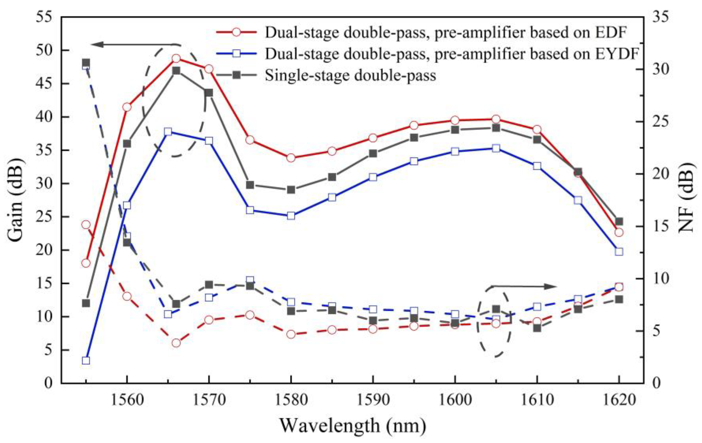
For further comparison, we changed the gain medium of the pre-amplifier to a 2.4 m long EYDF and pumped by 1480 nm LD with a power of 50 mW. The comparison of gain and NF characteristics is shown in Figure 3. After changing the gain medium of the pre-amplifier to EYDF, the dual-stage double-pass structure still maintains a relatively high gain level and gain bandwidth expansion compared to the single-pass structures. Nevertheless, by comparing two dual-stage double-pass structures, the gain is reduced by 2.89–14.75 dB and the NF is increased by 0.4–15.18 dB when using the EYDF in the pre-amplifier. Even compared with the double-pass structure without the pre-amplifier both gain and NF characteristics become worse. The gain reduction is >3 dB and the NF is as high as in the double-pass structure. Thus, EDF is more suitable for the gain medium of pre-amplifier than EYDF.
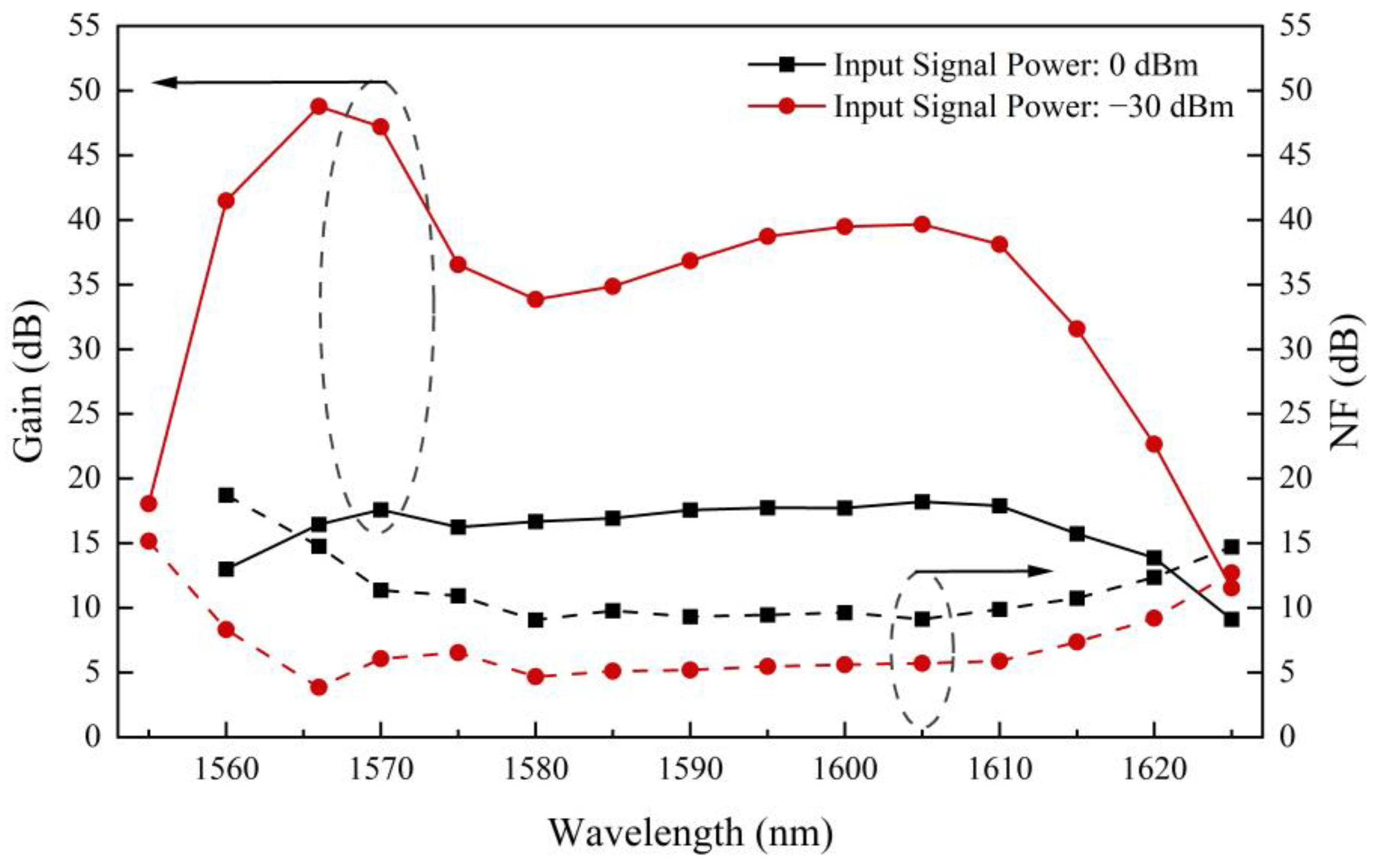
The gain and NF spectra of the dual-stage double-pass structure were tested also at an input signal power of 0 dBm, which is closer to the typical value of optical fiber transmission systems. The results compared with those of −30 dBm input signals are shown in Figure 4, indicating that the gain is reduced greatly to about 17.4 dB with variations less than 1.2 dB within the wavelength range of 1580–1615 nm. The NF is increased by 4–10.9 dB over that of the −30 dBm. Table 1 provides some precise numerical values for the gain and NF of all amplification structures. Obviously, the dual-stage double-pass structure exhibits the best overall performance compared with other structures in our work.
For the existing extended L-band EDFAs, a Ba-EDFA was demonstrated with a maximum gain of ~42 dB at 1568 nm, exhibiting a border bandwidth of ~63 nm, but the overall gain level was relatively low [7]. In 2023, an amplifier based on 1480 nm diode-pumped Er/Yb/P/Al co-doped fiber was reported with a maximum gain of ~30 dB at 1605 nm. Its gain spectrum was extended up to 1625 nm and the gain value was 15.5 dB at that wavelength [10]. In 2021, Chen et al. reported an Er/Yb/P co-doped fiber amplifier pumped by 1480 nm LDs. The 20 dB gain bandwidth reached 58 nm, and the maximum gain value was ~31 dB at 1605 nm [13]. In addition, Zeng et al. reported a two-stage Er/Bi/La co-doped fiber amplifier that also extended the gain spectra to 1625 nm at a gain of ~17 dB. And the maximum gain was obtained at 1566 nm of ~42 dB [18]. The detailed gain performance comparisons of those reported extended L-band EDFAs are shown in Table 2. Note that, in our work, the broadest bandwidth and the highest gain level are achieved at the lowest total pump power. Hence, the proposed dual-stage double-pass structure shows competitive performance in terms of high gain, border bandwidth and reasonable NF level.
Finally, the gain against input signal power at different wavelength channels: 1590, 1605, 1620 and 1621.4 nm were measured in the dual-stage double-pass structure. The measured output power data, as displayed in Figure 5, indicates that for the wavelength channels of 1590, 1605, 1620 and 1621.4 nm, the saturated output powers were 16.77, 20.58, 15.57 and 13.43 dBm, respectively, getting a high saturated output power in extended L-band. It is worth noting that the above results were achieved with all of the component insertion loss, ~2.3 dB and the splice losses of the fibers. So, the gain bandwidth is expected to be further extended by optimizing the system loss.
4. Conclusions
A dual-stage extended L-band EDFA with improved gain level has been demonstrated by using an Er/Yb/P co-doped fiber-based double-pass structure assisted by a low noise pre-amplifier. High gain levels of up to 48.79 dB at 1566 nm and 20.05 dB at 1621.4 nm are achieved under a total pump power of only 400 mW. Experimental results have indicated that a considerable gain enhancement of over 20 dB is obtained in most of the gain spectrum when compared with the single-stage single-pass structure. Bandwidths with a gain of more than 20 and 30 dB are reached up to 66 nm (1555.4–1621.4 nm) and 58.4 nm (1557.5–1615.9 nm), respectively, with the saturated output power at 1605 nm of 20.58 dBm. Meanwhile, the achieved bandwidth is increased to 1625 nm with a gain value of 11.53 dB. The noise figure benefited by using the low noise pre-amplifier is 5.40 ± 1.55 dB in the 1565–1610 nm range. The overall performance including the broad gain bandwidth, high gain level and relatively low pump power make this dual-stage, double-pass extended L-band EDFA very competitive for future optical fiber communication systems.
Author Contributions
Conceptualization, H.L. and X.D.; methodology, H.L., P.X. and X.D.; software, H.L., J.R. and M.L.; validation, H.L., J.R., M.L., L.Z. and S.W.; formal analysis, H.L., J.R., M.L., P.X. and X.D.; investigation, M.L., L.Z., S.W. and P.X.; resources, L.Z., S.W. and X.D.; data curation, H.L., M.L., P.X. and X.D.; writing—original draft preparation, H.L.; writing—review and editing, X.D.; supervision, P.X., L.Z. and S.W.; project administration, X.D. All authors have read and agreed to the published version of the manuscript.
Funding
This research was funded by the National Key Research and Development Program of China, grant number 2020YFB1805804, the National Natural Science Foundation of China, grant number 11974083 and the Program for Guangdong Introducing Innovative and Entrepreneurial Teams, grant number 2019ZT08X340.
Institutional Review Board Statement
Not applicable.
Informed Consent Statement
Not applicable.
Data Availability Statement
The data presented in this study are available upon request.
Conflicts of Interest
The authors declare no conflict of interest.
References
- Idler, W.; Buchali, F.; Schmalen, L.; Lach, E.; Braun, R.P.; Böcherer, G.; Schulte, P.; Steiner, F. Field trial of a 1 Tb/s super-channel network using probabilistically shaped constellations. J. Light. Technol. 2017, 35, 1399–1406. [Google Scholar] [CrossRef]
- Winzer, P.J.; Neilson, D.T.; Chraplyvy, A.R. Fiber-optic transmission and networking: The previous 20 and the next 20 years. Opt. Express 2018, 26, 24190–24239. [Google Scholar] [CrossRef] [PubMed]
- Cantono, M.; Schmogrow, R.; Newland, M.; Vusirikala, V.; Hofmeister, T. Opportunities and challenges of C+L transmission systems. J. Light. Technol. 2020, 38, 1050–1060. [Google Scholar] [CrossRef]
- Deng, N.; Zong, L.; Jiang, H.; Duan, Y.; Zhang, K. Challenges and enabling technologies for multi-band WDM optical networks. J. Light. Technol. 2022, 40, 3385–3394. [Google Scholar] [CrossRef]
- Singh, S.; Kaler, R.S. Flat-gain L-band Raman-EDFA hybrid optical amplifier for dense wavelength division multiplexed system. Photonics Technol. Lett. 2013, 25, 250–252. [Google Scholar] [CrossRef]
- Chung, H.S.; Lee, W.Y.; Chu, M.J.; Lee, Y.B.; Lee, H.H.; Lee, D.H. A low-noise L-band EDFA with a 1500-nm Raman-pumped dispersion-compensating fiber section. Photonics Technol. Lett. 2003, 15, 522–524. [Google Scholar] [CrossRef]
- Jalilpiran, S.; Fuertes, V.; Lefebvre, J.; Grégoire, N.; Durak, F.E.; Landry, N.; Wang, L.; Rivera, A.G.V.; Messaddeq, Y.; LaRochelle, S. Baria-silica erbium-doped fibers for extended L-band amplification. J. Light. Technol. 2023, 41, 4806–4814. [Google Scholar] [CrossRef]
- Lou, Y.; Chen, Y.; Gu, Z.M.; Qiu, Q.; Shi, C.J.; He, L.; Xing, Y.B.; Peng, J.G.; Li, H.Q.; Chu, Y.B.; et al. Er3+/Ce3+ co-doped phospho-silicate fiber for extend the L-band amplification. J. Light. Technol. 2021, 39, 5933–5938. [Google Scholar] [CrossRef]
- Qiu, Q.; He, L.; Gu, Z.M.; Chen, Y.; Lou, Y.; Zhao, X.Y.; Peng, J.G.; Li, H.Q.; Xing, Y.B.; Chu, Y.B.; et al. Extended L-band few-mode Er/Yb co-doped fiber amplifier with a cladding-pumped pseudo-two-stage configuration. Opt. Lett. 2022, 47, 2963–2966. [Google Scholar] [CrossRef]
- Zhai, Z.W.; Sahu, J.K. 1480 nm diode-pumped Er3+:Yb3+ co-doped phospho-alumino-silicate fiber for extending the L-band gain up to 1625 nm. J. Light. Technol. 2023, 41, 3432–3437. [Google Scholar] [CrossRef]
- Codemard, C.; Soh, D.; Ylä-Jarkko, K.; Sahu, J.; Laroche, M.; Nilsson, J. Cladding-pumped L-band phosphosilicate erbium-ytterbium co-doped fiber amplifier. In Proceedings of the Optical Amplifiers and Their Applications 2003, Otaru, Japan, 6–9 July 2003. [Google Scholar] [CrossRef]
- Masuda, H.; Miyamoto, Y. Low-noise extended L-band phosphorus co-doped silicate EDFA consisting of novel two-stage gain-flattened gain blocks. Electron. Lett. 2008, 44, 1082–1083. [Google Scholar] [CrossRef]
- Chen, Y.; Lou, Y.; Gu, Z.M.; Qiu, Q.; He, L.; Li, W.Z.; Yin, X.K.; Zhao, X.Y.; Liu, S.K.; Peng, J.G.; et al. Extending the L-band amplification to 1623 nm using Er/Yb/P co-doped phosphosilicate fiber. Opt. Lett. 2021, 46, 5834–5837. [Google Scholar] [CrossRef] [PubMed]
- Chu, Y.B.; Lou, Y.; Chen, Y.; Gu, Z.M.; Qiu, Q.; Liu, C.B.; Dai, N.L.; Li, J.Y. Ultra-broadband, high gain, and low noise extended L-band erbium-doped fiber and its amplification performance. Chin. J. Lasers 2021, 48, 0715001. [Google Scholar]
- Le, H.; Chu, Y.B.; Dai, N.L.; Li, J.Y. Silicate-based erbium-doped fiber extended to L-band and its amplification performance. Acta Phys. 2022, 71, 154204. [Google Scholar]
- Firstov, S.V.; Khopin, V.F.; Bufetov, I.; Firstova, E.; Guryanov, A.N.; Dianov, E. Combined excitation-emission spectroscopy of bismuth active centers in optical fibers. Opt. Express 2011, 19, 19551–19561. [Google Scholar] [CrossRef]
- Firstov, S.V.; Riumkin, K.; Khegai, A.; Alyshev, S.V.; Melkumov, M.; Khopin, V.F.; Afanasiev, F.V.; Guryanov, A.N.; Dianov, E. Wideband bismuth and erbium co-doped optical fiber amplifier for C+L+U-telecommunication band. Laser Phys. Lett. 2017, 14, 110001. [Google Scholar] [CrossRef]
- Zeng, L.Z.; Wen, J.X.; Wu, Y.; Yang, L.; Pang, F.F.; Wang, T.Y. Exceeding 25 dB gain broad-spectrum amplification in L-band based on a Bi/Er/La co-doped silica fiber. IEEE Photonics Technol. Lett. 2023, 35, 990–993. [Google Scholar] [CrossRef]
- Lei, C.M.; Feng, H.L.; Messaddeq, Y.; LaRochelle, S. Investigation of C-band pumping for extended L-band EDFAs. J. Opt. Soc. Am. B 2020, 37, 2345–2352. [Google Scholar] [CrossRef]
- Lei, C.M.; Feng, H.L.; Messaddeq, Y.; LaRochelle, S. Investigation of bi-directionally, dual-wavelength pumped extended L-band EDFAs. IEEE Photonics Technol. Lett. 2020, 32, 1227–1230. [Google Scholar] [CrossRef]
- Bolshtyansky, M.; Mandelbaum, I.; Pan, F. Signal excited-state absorption in the L-band EDFA: Simulation and measurements. J. Light. Technol. 2005, 23, 2796–2799. [Google Scholar] [CrossRef]
- Townsend, J.E.; Barnes, W.L.; Crubb, S.G. Yb3+ sensitised Er3+ doped silica optical fibre with ultra-high transfer efficiency and gain. MRS Online Proc. Libr. 1991, 244, 143–147. [Google Scholar] [CrossRef]
- Likhachev, M.; Bubnov, M.; Zotov, K.; Lipatov, D.; Yashkov, M.; Guryanov, A.N. Effect of the AlPO4 join on the pump-to-signal conversion efficiency in heavily Er-doped fibers. Opt. Lett. 2009, 34, 3355–3357. [Google Scholar] [CrossRef] [PubMed]
- Kobayashi, Y.; Sekiya, E.H.; Banno, M.; Nishimura, R.; Okazaki, T.; Hashimoto, Y.; Araki, T.; Ichii, K.; Saito, K. Effect of P-to-rare earth atomic ratio on energy transfer in Er-Yb-doped optical fiber. J. Light. Technol. 2020, 38, 4504–4512. [Google Scholar] [CrossRef]
- Nilsson, J.; Yun, S.Y.; Hwang, S.T.; Kim, J.M.; Kim, S.J. Long-wavelength erbium-doped fiber amplifier gain enhanced by ASE end-reflectors. IEEE Photonics Technol. Lett. 1998, 10, 1551–1553. [Google Scholar] [CrossRef]
- Hwang, S.T.; Song, K.W.; Kwon, H.J.; Koh, J.; Oh, Y.J.; Cho, K. Broad-band erbium-doped fiber amplifier with double-pass configuration. IEEE Photonics Technol. Lett. 2001, 13, 1289–1291. [Google Scholar] [CrossRef]
- Haleem, M.R.; Al-Mansoori, M.H.; Jamaludin, M.Z.; Abdullah, F.; Din, N.M. High gain double-pass L-band EDFA with dispersion compensation as feedback loop. Laser Phys. 2011, 21, 419–422. [Google Scholar] [CrossRef]
- Chang, C.L.; Wang, L.; Chiang, Y.J. A dual pumped double-pass L-band EDFA with high gain and low noise. Opt. Commun. 2006, 267, 108–112. [Google Scholar] [CrossRef]
- Mishra, A.R.; Kakade, R.N.; Kakade, P.D. Dual-stage EDFA for improving the performance of long-haul optical systems. IEEE Access 2022, 10, 13496–13514. [Google Scholar] [CrossRef]
- Bouzid, B. High-gain and low-noise-figure erbium-doped fiber amplifier employing dual stage quadruple pass technique. Opt. Rev. 2010, 17, 100–102. [Google Scholar] [CrossRef]
- Delavaux, J.M.P.; Nagel, J.A. Multi-stage erbium-doped fiber amplifier designs. J. Light. Technol. 1995, 13, 703–720. [Google Scholar] [CrossRef]
Figure 1.
The proposed extended L-band EDFA with dual-stage double-pass structure.

Figure 2.
The gain (a) and NF (b) spectra of various amplification structures for an input signal power of −30 dBm.
Figure 2.
The gain (a) and NF (b) spectra of various amplification structures for an input signal power of −30 dBm.

Figure 3.
Gain and NF characteristics for the double-pass configuration with pre-amplifier based on different gain media at input signal power of −30 dBm.
Figure 3.
Gain and NF characteristics for the double-pass configuration with pre-amplifier based on different gain media at input signal power of −30 dBm.

Figure 4.
Gain and NF spectra for the pre-amplified double-pass configuration at the input signal power of 0 and −30 dBm.
Figure 4.
Gain and NF spectra for the pre-amplified double-pass configuration at the input signal power of 0 and −30 dBm.

Figure 5.
Measured gain against input signal power for various wavelength channels of 1590, 1605, 1620 and 1621.4 nm in the dual-stage double-pass structure.
Figure 5.
Measured gain against input signal power for various wavelength channels of 1590, 1605, 1620 and 1621.4 nm in the dual-stage double-pass structure.


Table 1.
Amplification performance comparison of six structures.
| Structure | Pump Power (mW) | Gain Values (dB) | NF Values (dB) | ||
|---|---|---|---|---|---|
| @1566 nm | @1605 nm | @1566 nm | @1605 nm | ||
| Dual stage double pass | 50 + 300 + 50 | 48.79 | 39.66 | 3.86 | 5.71 |
| Single stage double pass | 300 + 50 | 46.96 | 38.36 | 7.59 | 7.70 |
| Dual stage single pass | 50 + 300 + 250 | 42.48 | 23.05 | 3.80 | 5.74 |
| 50 + 300 + 50 | 36.62 | 21.39 | 3.75 | 5.61 | |
| Single stage single pass | 300 + 250 | 39.66 | 22.57 | 5.70 | 5.10 |
| 300 + 50 | 27.85 | 18.76 | 4.87 | 5.04 | |
Table 2.
Reported gain performance of extended L-band EDFAs in recent years.
| Doped Ions | Fiber Length (m) | Total Pump Power (mW) | Gain Bandwidth (nm) | Maximum Gain (dB) | Minimum NF (dB) | Refs. |
|---|---|---|---|---|---|---|
| Er/Yb/P | 68 | 720 | 58 (≥20 dB, 1565–1623) | ~31 @ 1605 nm | ~4.4 @ 1605 nm | [13] |
| Er/P/Al | 19 + 26 + 10 | 2180 | ~50 (≥23 dB, 1575–1625) ~33 (≥30 dB, 1590–1623) | ~37 @ 1605 nm | 4.7 @ 1605 nm | [15] |
| Er/Yb/P/Al | 62 | 1200 | ~53 (≥19 dB, 1570–1623) | ~30 @ 1605 nm | 4.6 @ 1605 nm | [10] |
| Er/Ba | 125 | 800 | ~63 (≥20 dB, 1560–1623) ~15 (≥30 dB, 1562–1577) | ~42 @ 1568 nm ~26 @ 1615 nm | / | [7] |
| Er/Bi/La | 11 + 39 | 1880 | 58 (≥25 dB, 1562–1620) | ~42 @ 1566 nm ~31 @1610 nm | 5.8 @ 1610 nm | [18] |
| EDF+ Er/Yb/P | 10 + 30 (double pass) | 400 | ~66 (≥20 dB, 1556–1621) ~58 (≥30 dB, 1558–1616) | ~49 @ 1566 nm ~40 @ 1605 nm | 3.86/4.67 @1566/1580 nm | This work |
Disclaimer/Publisher’s Note: The statements, opinions and data contained in all publications are solely those of the individual author(s) and contributor(s) and not of MDPI and/or the editor(s). MDPI and/or the editor(s) disclaim responsibility for any injury to people or property resulting from any ideas, methods, instructions or products referred to in the content. |
© 2023 by the authors. Licensee MDPI, Basel, Switzerland. This article is an open access article distributed under the terms and conditions of the Creative Commons Attribution (CC BY) license (https://creativecommons.org/licenses/by/4.0/).
Share and Cite
MDPI and ACS Style
Lao, H.; Ruan, J.; Lin, M.; Zhong, L.; Wang, S.; Xu, P.; Dong, X. Dual-Stage Double-Pass Extended L-Band Erbium-Doped Fiber Amplifier with Improved Gain Performance. Photonics 2023, 10, 1266. https://doi.org/10.3390/photonics10111266
AMA Style
Lao H, Ruan J, Lin M, Zhong L, Wang S, Xu P, Dong X. Dual-Stage Double-Pass Extended L-Band Erbium-Doped Fiber Amplifier with Improved Gain Performance. Photonics. 2023; 10(11):1266. https://doi.org/10.3390/photonics10111266
Chicago/Turabian StyleLao, Haoxian, Jiyu Ruan, Manbing Lin, Li Zhong, Song Wang, Pengbai Xu, and Xinyong Dong. 2023. "Dual-Stage Double-Pass Extended L-Band Erbium-Doped Fiber Amplifier with Improved Gain Performance" Photonics 10, no. 11: 1266. https://doi.org/10.3390/photonics10111266
Note that from the first issue of 2016, this journal uses article numbers instead of page numbers. See further details here.